Article

Testing of Conductive Carbon Fiber Reinforced Polymer Composites Using Current Impulses Simulating Lightning Effects

1
Department of Electrical and Computer Engineering Fundamentals, Rzeszow University of Technology, ul. W. Pola 2, 35-959 Rzeszów, Poland
2
Department of Polymer Composites, Rzeszow University of Technology, Al. Powstańców Warszawy 6, 35-959 Rzeszów, Poland
*
Author to whom correspondence should be addressed.
Energies 2021, 14(23), 7899; https://doi.org/10.3390/en14237899
Submission received: 11 October 2021 / Revised: 17 November 2021 / Accepted: 22 November 2021 / Published: 25 November 2021

Abstract

:
Carbon fiber reinforced polymer (CFRP) composites are lightweight and an increasingly used material with good mechanical properties. In the aviation industry, they are also required to have specific electrical properties that guarantee resistance to the direct and indirect lightning effects. The paper is focused on the description of a test stand and development of a method used to determine the electrical characteristics of conductive CFRP laminate samples with the use of high current impulses of lightning nature. Samples of three laminates (square format with side 30 × 30 cm) with a different composition were tested on the constructed stand, confirming the possibility of characterizing this type of laminate sample in terms of electrical conductivity and resistance to the effects of lightning current. It was possible to observe the impulse current flow (with a peak value up to 15 kA and a rise time above 6 µs) from the high voltage electrode placed in the center of the sample in all directions towards the edge. The optical fiber measuring system was used to record the voltage and current time waveforms. The energy stored in the impulse current generator was sufficient to simulate the mechanical damage, such as burnout and delamination, that accompanies the direct lightning strike to structural elements made of CFRP. The influence of the matrix composition used for laminate fabrication on the test results describing the electrical properties of the tested CFRP samples was noted. The experimental setup allows the testing of specimens with a maximum width and length of 50 × 50 cm and any thickness with a peak current of up to 50 kA.

1. Introduction

A constant improvement and development of aircraft materials is among the most important activities of engineers. Highly promising in this field are composite elements [1,2,3,4,5,6,7,8,9]. Their structure comprises conducting materials and polymers, and allows a significant lowering of the airplane weight without a major reduction in their durability and electrical conductivity. Composites show a good resistance to weather conditions such as rain, temperature, and ice, but their immunity to lightning interaction is a critical parameter that can prevent the application of even the most promising material.
Lightning can damage a composite in several different ways [10,11,12,13,14]. A mechanical, thermal, chemical, and electrical change in the structure of composite material during the impact of lightning discharges is observed. The defects such as wrinkles in the carbon fiber may have a strong effect on the mechanical properties of the composites [15,16,17]. In order to pass the tests against lightning, the durability in all mentioned areas should be at satisfying level. Lightning acts on a composite mainly through the electrical current. There are two main types of lightning current components [18,19,20,21,22,23] that can damage this material. The first, a stroke-type lightning current, having peak values of several tens of kiloampers and rising times of less than microsecond, is responsible mainly for electrical and mechanical effects of lighting [24]. The second type, a continuing current, having a much lower peak value of less than 1 kA but a longer duration, generates a high rise in temperature in the composite, thus causing thermal and chemical destruction. A good material for aircraft structures should be protected against both components of lightning current.
Sequences of lightning tests of composite materials are usually arranged in high voltage (HV) laboratories [25,26,27,28,29,30,31]. The application of special generators allows the behavior of a particular material to be checked for repeatable artificial lightning strokes [32]. Different testing procedures have been applied all over the world. An auxiliary recording of voltage signal is often omitted by research reports of lighting protection tests of composites. Focusing on the lightning current distribution rather than on voltage results from the need to analyze primarily the direct source of the losses, and therefore, greater accessibility and specification of lighting current distributions is presented in the literature.
However, there is still a necessity for voltage signal measurement for, among other reasons, impedance estimation purposes. The resistance of composite samples allows their electrical conductivity to be computed. This parameter enables the prediction of the behavior of a particular material for different peak values or types of lightning current. Moreover, the characteristics of the composites for different sample geometries can be estimated. Resistivity or conductance of a particular material is one of the fundamental input parameters during the numerical simulation of their electrical properties [10,11,14,33].
This paper is focused on the construction of a prototype test stand for developing of a measurement method that enables the determination of the electrical parameters of conductive composites during high-current tests. Some significant changes and improvements in the measurement setup and test bed design were made in comparison to the solutions described in the literature [34]. The new proposal allows, among other features, the parallel acquisition of a voltage and the corresponding current waveforms during the conducted tests.

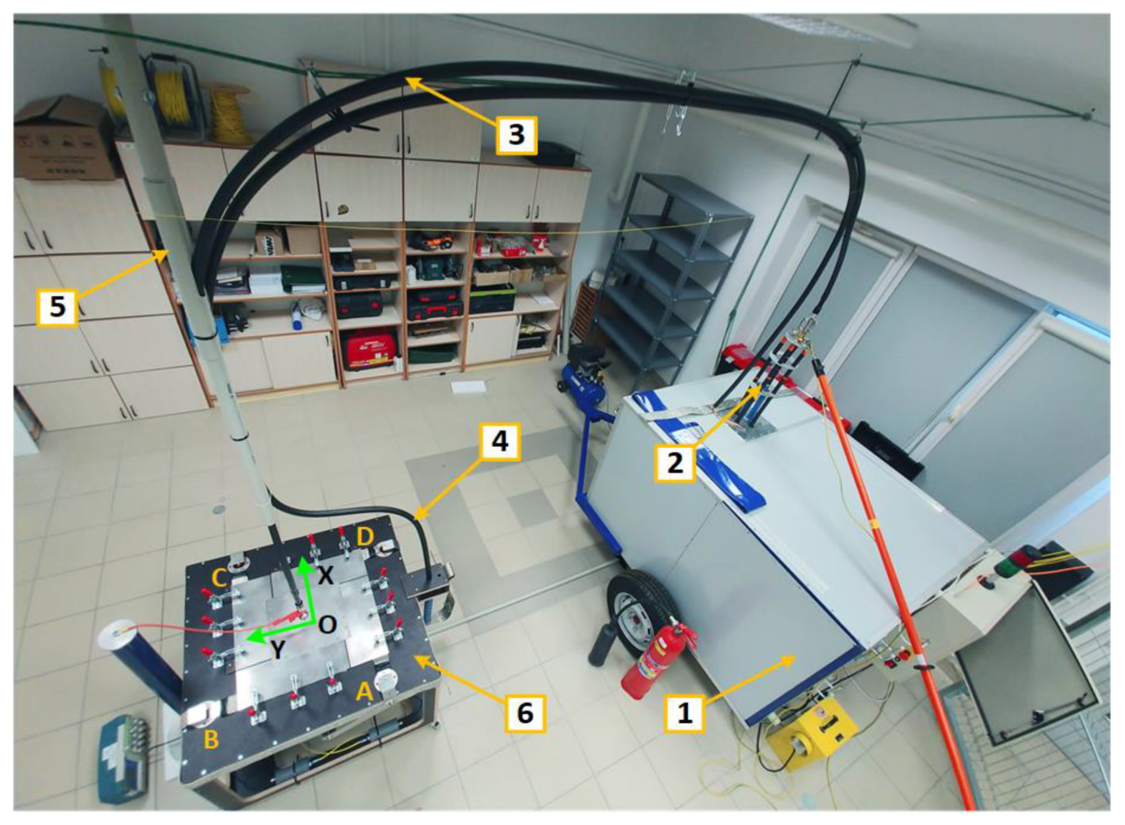
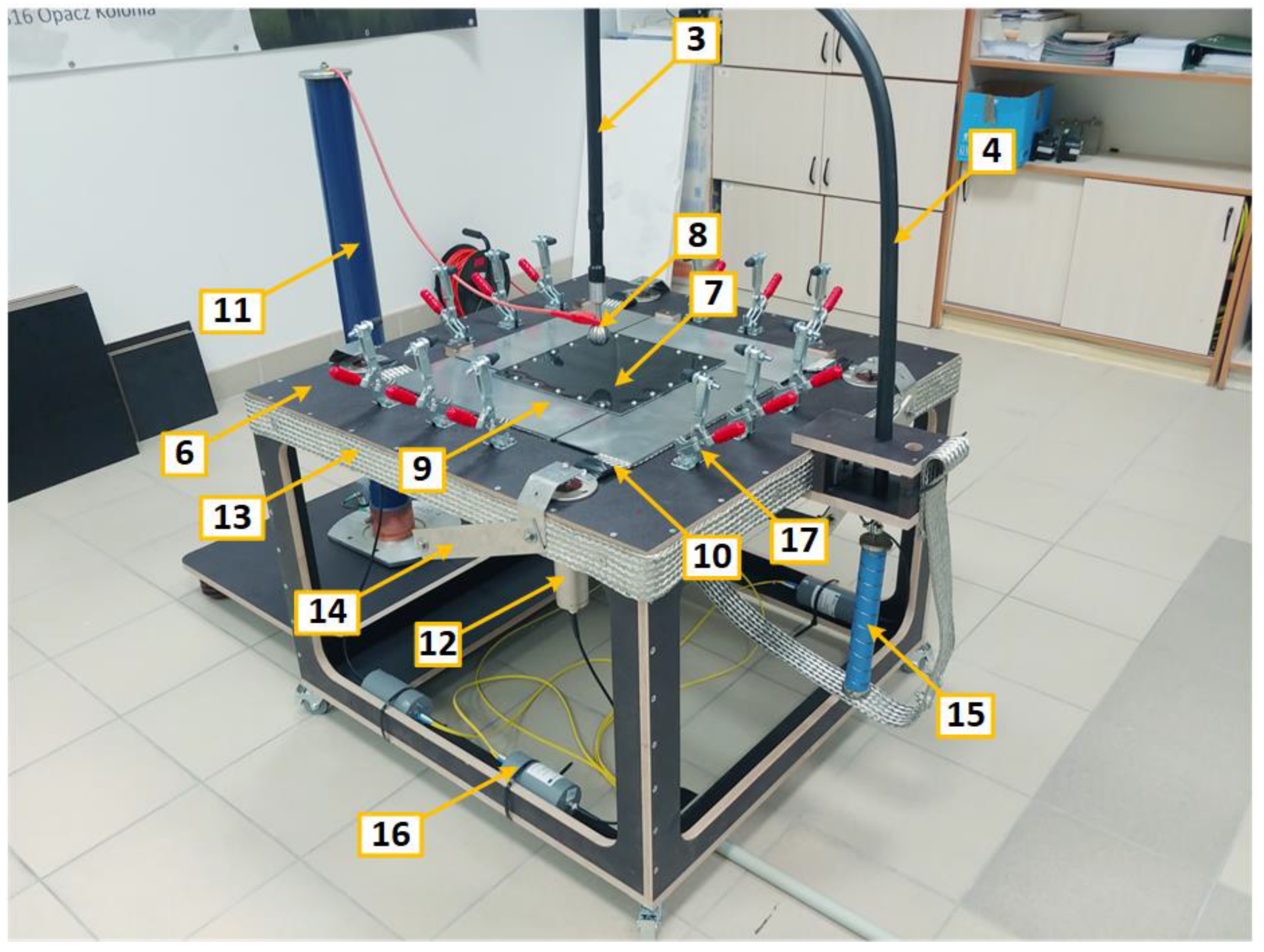
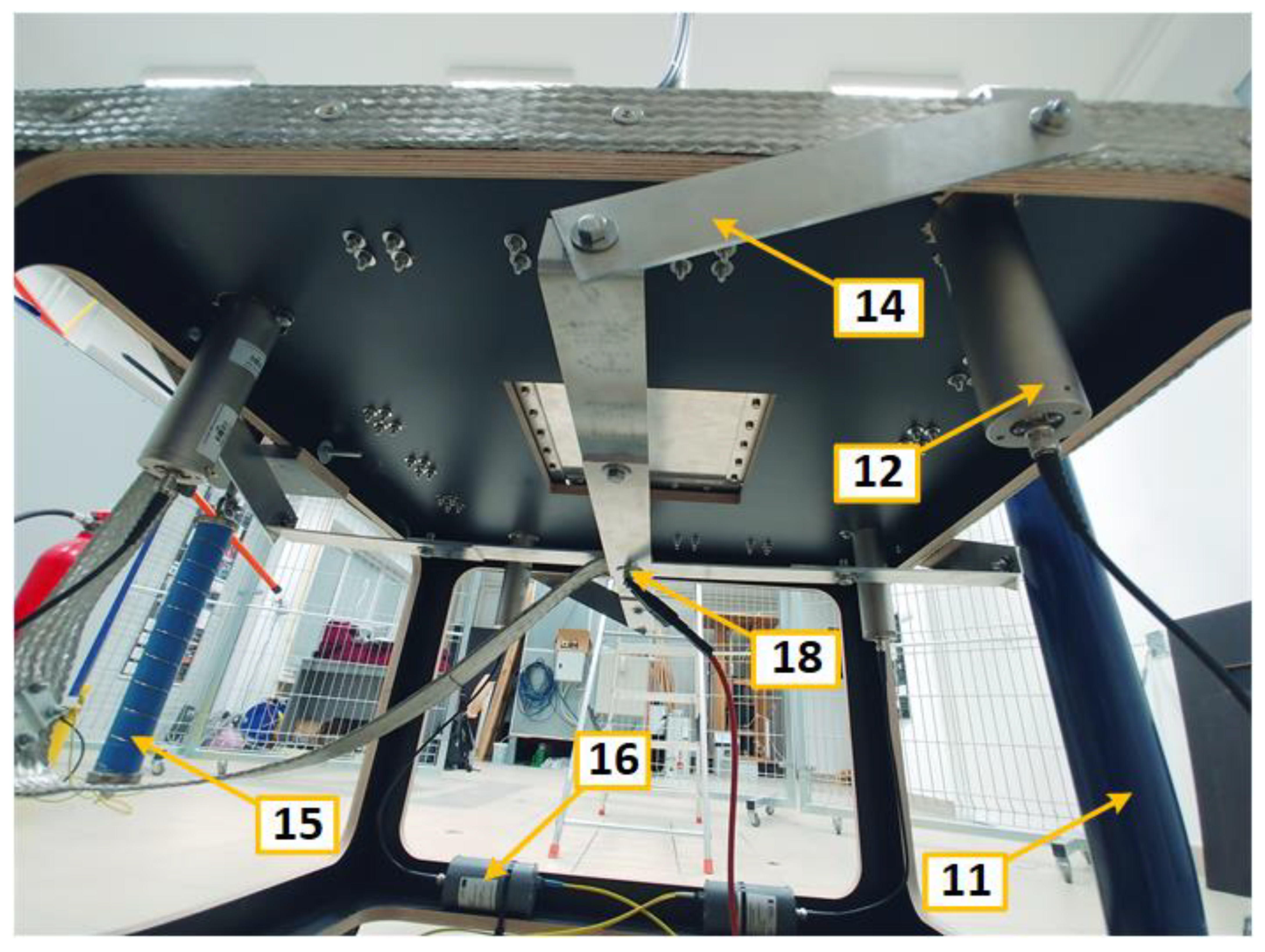
2. Measurement System and Components Layout

The solution presented below was obtained through successive approaches. At the outset, it was assumed that the designed test stand should provide a convenient, fast, and minimal connection resistance method for assembling laminate samples with dimensions not exceeding 50 cm in length and width. During the high-current tests, it should be possible to measure the impulse current flowing from the center of the sample towards its sides and the voltage drop along the current flow path. It was assumed that the tests would be performed with the use of available generators simulating various components of the lightning discharge.
The measurement system consisted of a lightning-type impulse generator with appropriate connecting cables and a control system. The test table on which the samples were placed was equipped with special electrodes and a sample mounting system. It was integrated with a voltage divider and current shunts connected to the acquisition system via a fiber optic link. The layout of the components is shown in Figure 1, Figure 2, Figure 3.
A GUP-8-10 lightning current pulse generator (marked in Figure 1 as number 1) from the Telab company was used for this research. This consists of a bank of eight type IK-0.4/100 capacitors with a total capacitance of 3.2 µF, which allows the accumulation of energy of about 10 kJ at the voltage of 80 kV. The shape of the obtained surges strongly depends on the character of the load. The generator enables the use of repeatable impulses with the voltage peak value set in a control system connected by the fiber optic link. As a result of preliminary tests with several solutions, the connection of the generator with the test table was finally made using hanging HV copper conductors (3) and (4) with a cross-section of 35 mm2. The high-voltage conductor (3) was placed near the return conductor (4) to minimize the inductance of the loop between those two cables. This bifilar arrangement of the cables allowed their total self-inductance to be decreased by about ten times (approximately up to 0.55 µH) in respect to the straight cable of the same length, where the return conductor would be routed near the floor.
The test table (6) with a tabletop size of 90 × 90 cm and a height of 70 cm was constructed from electro-insulating and mechanically durable material—18 mm thick birch plywood impregnated and coated with textolite on both sides. A central slot was cut in its top to allow the installation of composite panel samples (7) with side sizes up to 50 cm. These are exposed to voltage or current surges applied using a steel ball electrode (8) with diameter of 40 mm located centrally in relation to the panel, with the possibility of adjusting the distance to the laminate surface. Before being placed on the table, the panels were bolted to four aluminum flat bars (9), which were arranged in such a way that each of them, placed along the side of the specimen, overlapped it by 25 mm. They were bolted with five M6 screws with a torque of 9 Nm each. There was a gap of 5 mm between adjacent plates. In this way, in addition to ensuring good conductivity of the surge current i(t) through the aluminum elements (9) to the copper braided tapes (10) with cross-sectional area of 120 mm2, it was possible to evaluate the current distribution in the specimen from its center towards its edges. This allowed analysis of the influence of laminate structure on its conductivity as a function of direction. Therefore, in order to correlate the internal structure of the panels with the test results, the OX and OY axis designations given during laminate fabrication were kept. The plates lying on the tapes (10) were pressed evenly by the mounting clamps (17). From the side of the panel the current flowed sequentially through the elements (9), (10), (12), (14), and (13), and summed at point (18) to flow next through (15) and (4).
The four ISM 5P/10 current shunts (12) from HILO-TEST with resistance of 10 mΩ, action integral of 20 kA2s, and the possibility of measuring DC signals and transient signals with a frequency range up to 200 MHz, were used to register currents named iA(t), iB(t), iC(t), iD(t) (according to points A, B, C, D as shown in Figure 1), that flow to each edge of the sample. The voltage u(t) developed along the current flow path from the HV electrode to one side of the specimen (to one of aluminum plates) was measured using a HV resistive divider with a 1:2250 ratio with the bandwidth up to 5 MHz. The measurement signals from both the shunts and the divider were recorded in digital form using a fiber optic measurement system (16) with an ADC converter with a sampling rate of 50 MHz and a resolution of 12 bits.
The configuration of the return circuit shown in Figure 1, Figure 2, Figure 3 in the form of the connection of the element (13) with the current bars (14) connecting then together in the point (18) is a result of changes that were made after observing the currents during functional tests of the stand (see Figure 4) without the elements (14) and their connection (18).
Samples of three different composite laminates, named CFRP1, CFRP2, and CFRP3, were tested. Each was manufactured using five layers of carbon fiber fabric 2/2 with a gradation of 200 g/m2 and the vacuum-assisted resin infusion method. The first contained only unmodified epoxy resin (Epidian® 624 (EP) produced by Ciech-Sarzyna Plant, Poland), whereas the other two had additionally 25% of flame retardant (Methyl(5-methyl-2-methyl-1,3,2-dioxaphosphorinan-5-yl)ester,P,P’-dioxide produced by CT90, WTH, GmbH, Germany) added. CFRP2 also contained 0.25%, whereas CFRP3 had 0.75%, conductive carbon black (Saze Chezacarb Advanced Conductive AC-60, manufactured by UNIPETROL RP). The samples were cut into square formats with sides of 30 × 30 cm. Due to the nature of fabrication, uniform panel thicknesses were not obtained and were ultimately 1.51 mm (CFRP1), 1.66 mm (CFRP2), and 1.65 mm (CFRP3), respectively.

3. Results

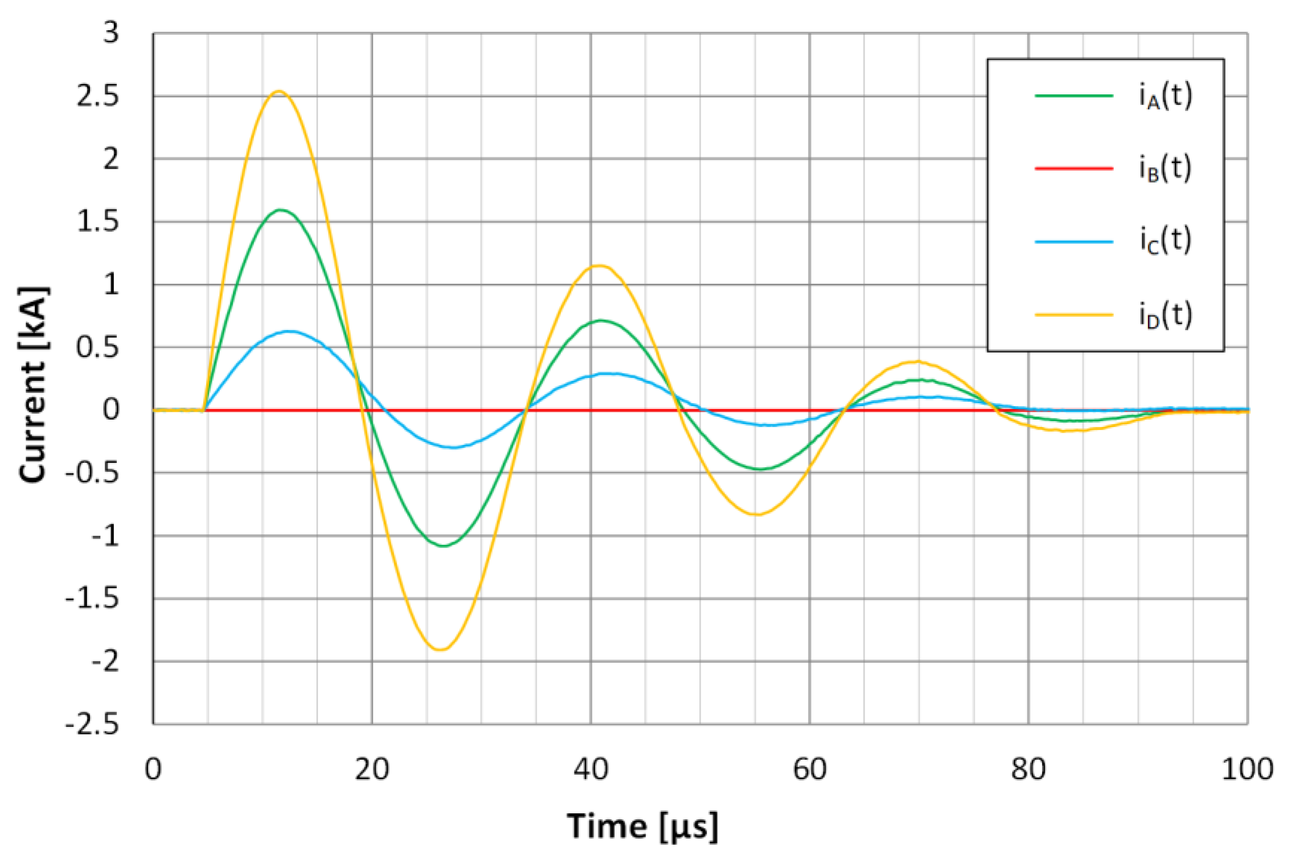
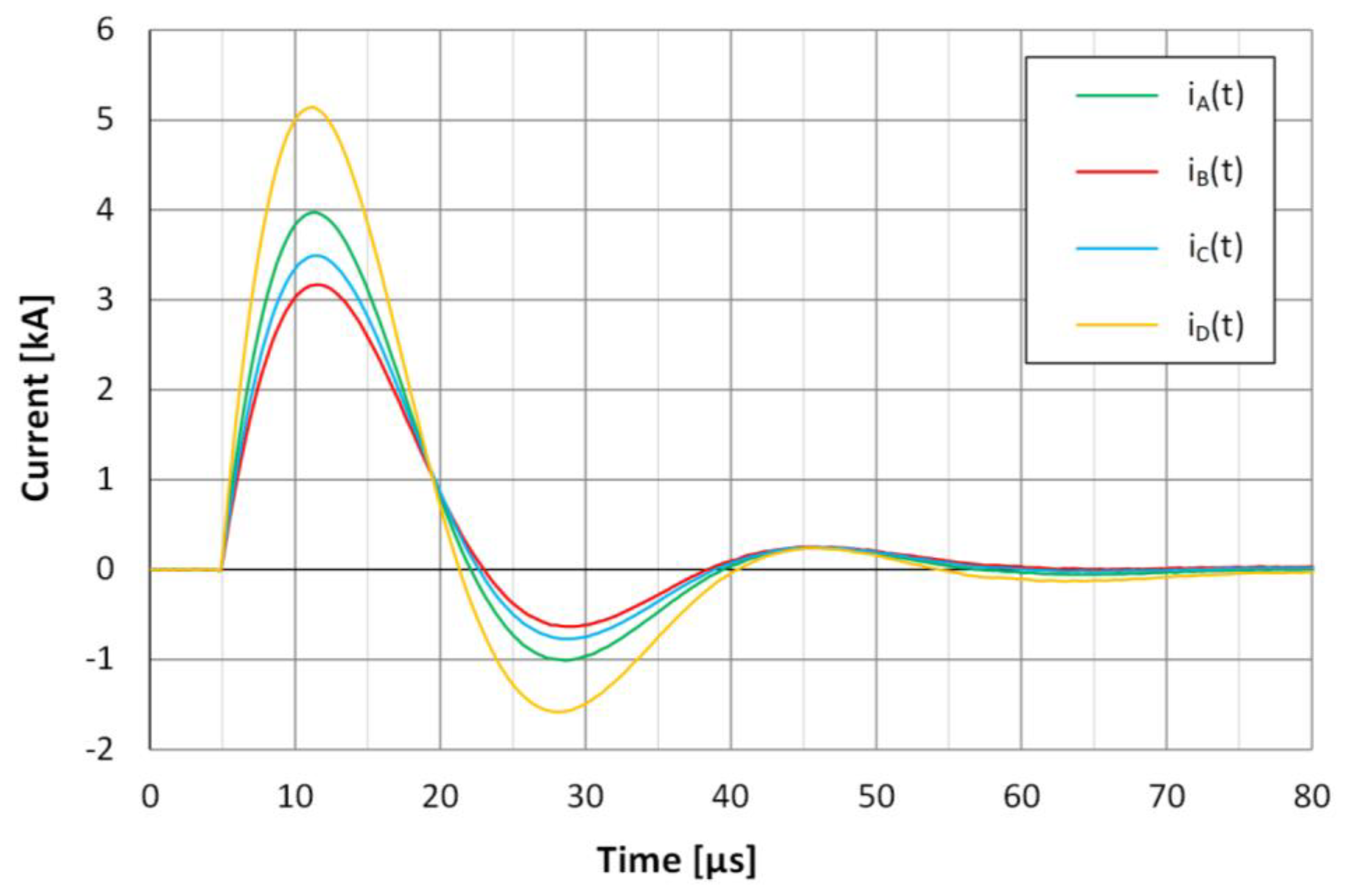
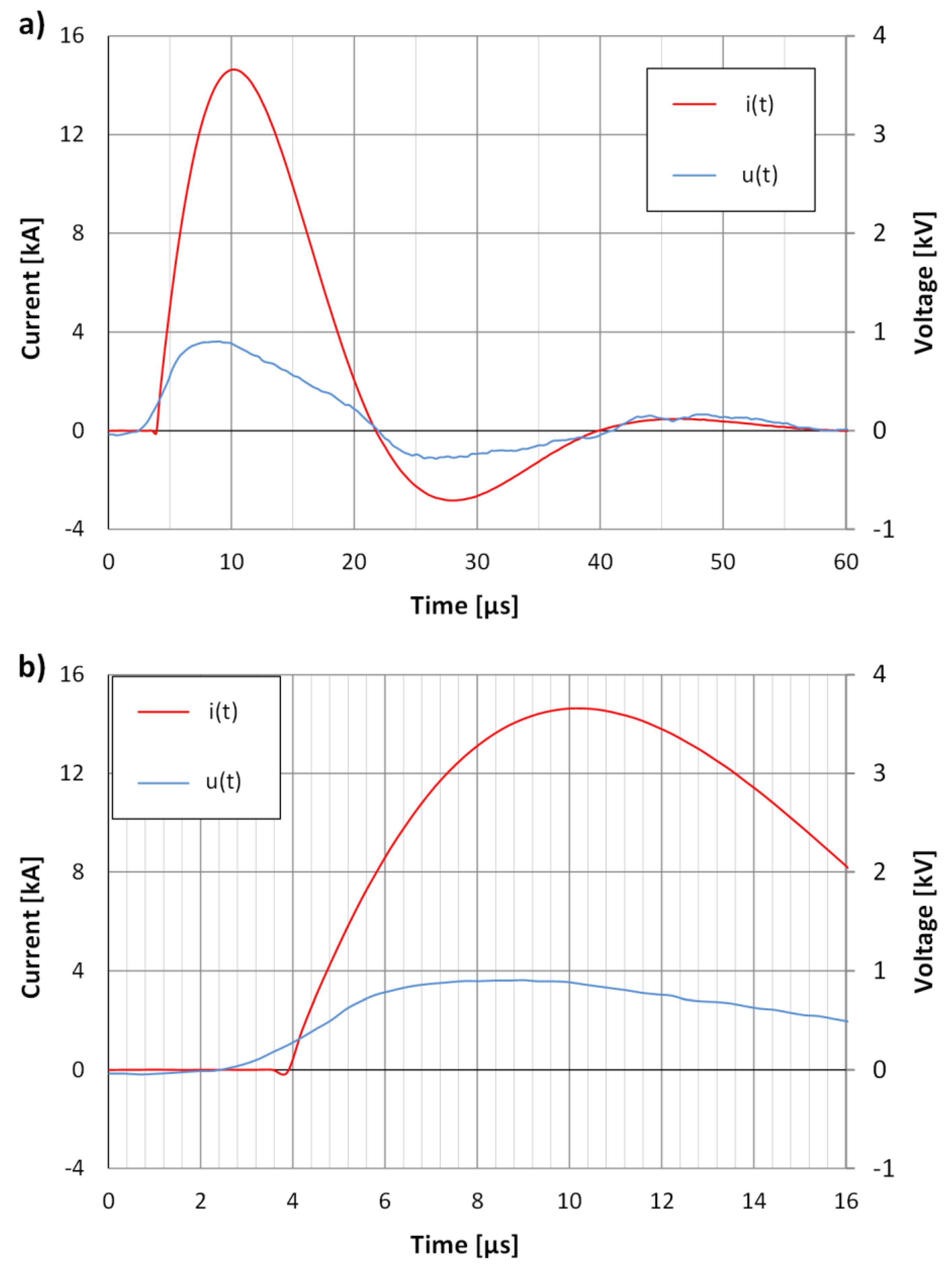
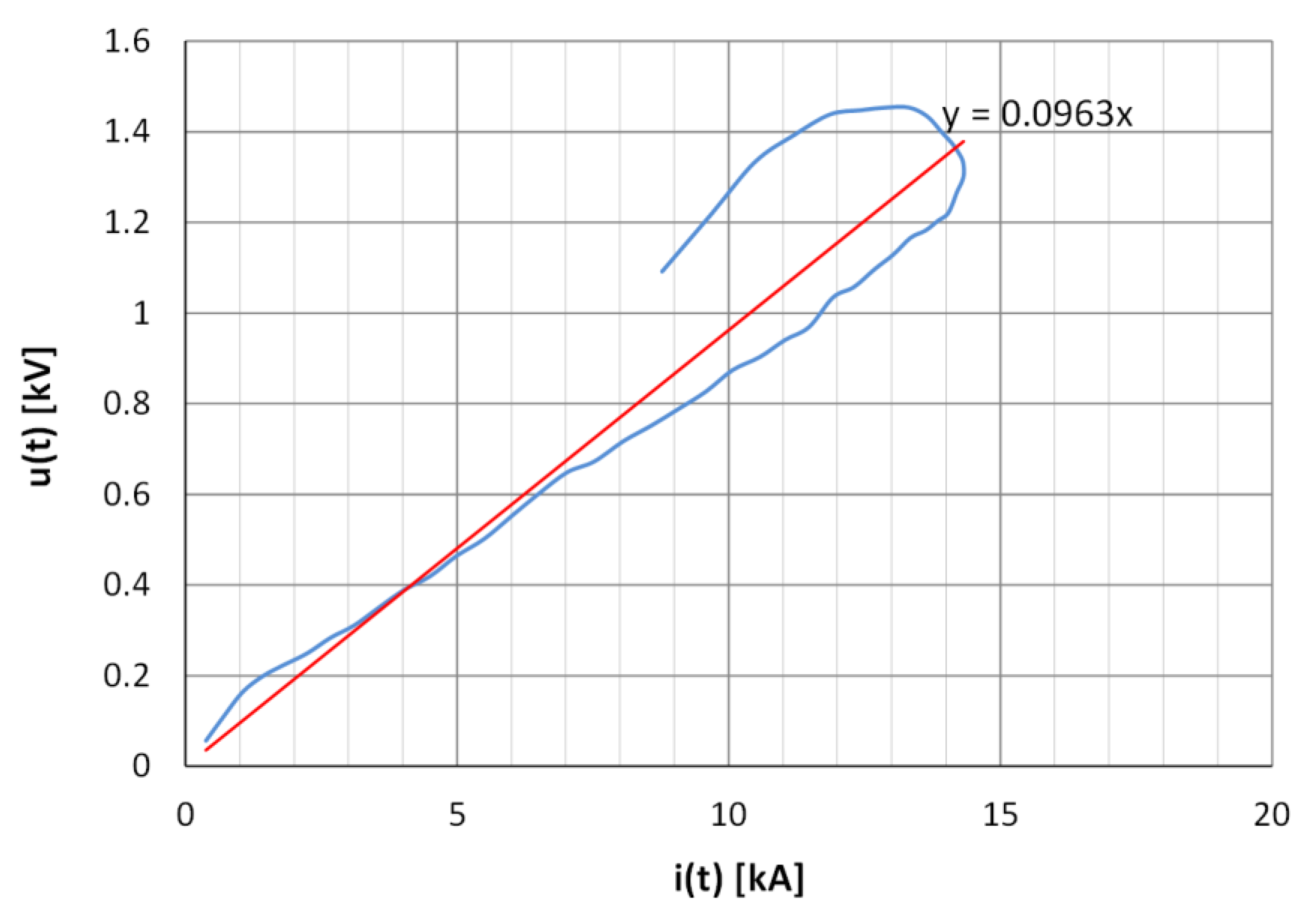
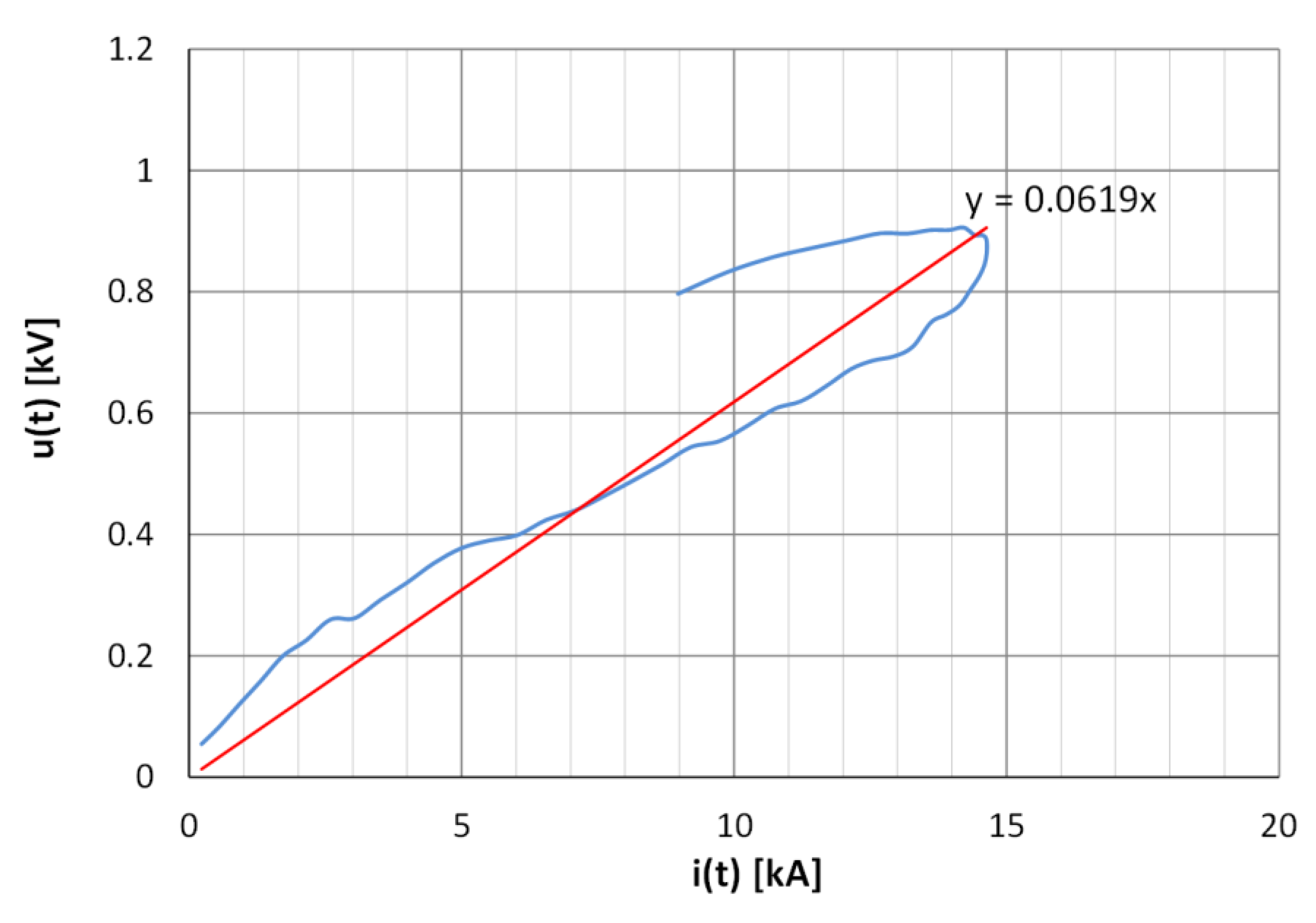
3.1. Functional Testing and Calibration

Figure 4 shows the current distribution in the aluminum plate during functional testing of the first design solution, especially concerning the return circuit with the asymmetrical tape arrangement (part 13 on Figure 1 and Figure 2), which manifested itself in a significant variation in the peak values of the observed currents. In this case, a 10 kV charge voltage of the surge generator was applied and a peak current of about 4.8 kA was obtained at the HV output. The level of current value iB(t) was not sufficient to exceed the measurement system trigger threshold. The shapes of the other currents were close together. They differed in rise times from 0 to the maximum value. The shortest (equal to 7 µs) was observed for iD(t) and the longest (8 µs) for iC(t). The maximum values for currents iD(t), iA(t), and iC(t) were as follows: 2.55, 1.6, and 0.63 kA.
Figure 4. Current distribution in an aluminum calibration plate during one of the preliminary tests for the first solution of the test bench design.
Energies 14 07899 g004
A significant asymmetry of the currents mentioned above was noted, which was also made evident in the work [34]. With a homogeneous sample, which was an aluminum plate at the time of calibration, and the central position of the HV electrode, the recorded currents flowing to each side of the sample should be comparable with each other. The proposed solution reduced the asymmetry in the return circuit part. By compression, the asymmetry associated with the unilateral connection of the HV wires to the generator remained. Figure 5 shows the current transients for the final setup and at the generator charge voltage of 40 kV.
Previously, the peak value of current iD(t) was over four times greater than that of iC(t), whereas after the changes it differed by 47%. The addition of a current pulse shaping element (15) in the form of an inductance of 0.5 µH and a resistance of 0.8 Ω in the return circuit allowed the current oscillations to be reduced and the aperiodic character of the surge current to be better approximated.

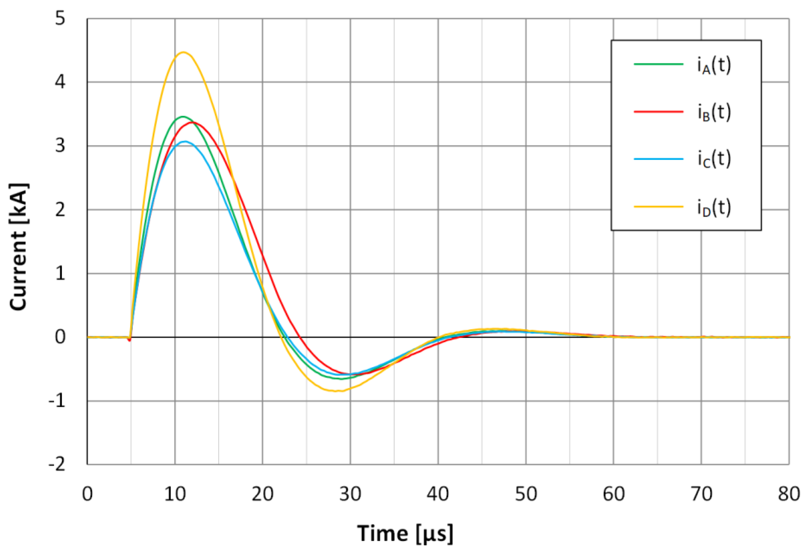
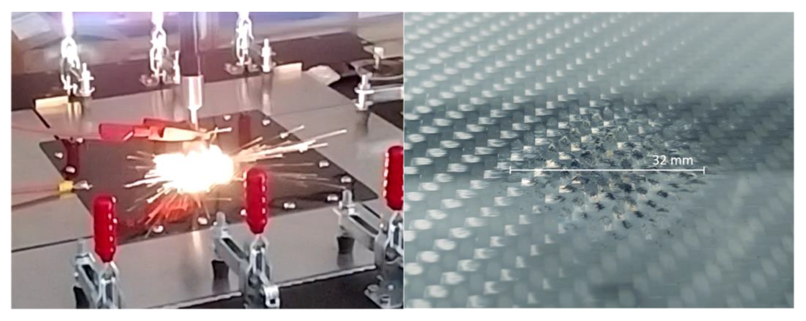
3.2. Tests of CFRP Samples

Testing of the prepared three laminate specimens was performed using the system configuration described in the previous section. Each of them was subjected to five current pulses occurring at intervals of 2 min. The HV electrode touched the surface of the samples. The generator output voltage in the no-load condition was 40 kV.
Figure 6 and Figure 7 show the current and voltage recordings during the test of the CFRP1 panel with the first pulse. Analyzing the currents shown in Figure 6, they were found to be oscillatory, but with a faster damping than seen during calibration with the aluminum plate due to the higher resistance of the panels compared to the aluminum plate. The currents flowing to each specimen side from the center of the sample differed noticeably in peak level and little in shape. The moment at which the peak values were achieved was practically the same for currents iA(t), iC(t), and iD(t). For current iB(t), this moment was delayed by about 1.2 µs. The peak values were 3.46, 3.37, 3.07, and 4.47 for currents iA(t), iB(t), iC(t), and iD(t), respectively.
The asymmetry of the measuring system mentioned above may have influenced the variation of the peak values of the measured component currents, as shown for the test with the aluminum plate. The uneven current distribution can be also determined by the structure of the samples. Such an effect can be induced by the orientation of the reinforcement fibers and the irregular concentration of conductive additives in the resin resulting from the manufacturing process.
By comparison, the current delay iB(t) observed in Figure 6 was not due to the individual electrical properties of the sample and its structure. It depended on the experimental setup which needs further improvements.
The recorded voltage as shown in Figure 7 had significant noise, which may have been caused by both conducted and radiated disturbances acting mainly on the voltage divider and its connections when the generator was discharged. In order to use the recorded voltage signal for further calculations, its processing was applied, and consisted of removal of oscillatory pulses on the rising edge, approximation of the edge with the MATLAB function interp1() using the “cubic” type of curve fitting based on the data before and after the rising front. In addition, the voltage was filtered with the smooth() function with a window parameter of 10 samples—this is a “moving average MA” filter. In the future, it is planned to improve the voltage measurement method to reduce the noise. A voltage divider with a smaller divider ratio can also be used. This would improve the resolution of the signal recorded with use of the fiber optic system. A comparison of the u(t) voltage (filtered) and i(t) current obtained by the CFRP3 panel measuring at the last pulse is shown in Figure 8. The time difference of about 2 µs between the moments of maximum values in the voltage and current waveforms suggests that the circuit was of a resistive-inductive nature. The return circuit connections and the cable connections to the HV divider may have been primarily responsible for the presence of inductance.
Table 1 summarizes the currents and voltage peaks for each sample. The observed results for individual samples are not as varied as one might expect knowing that each laminate had a different filler. In a percentage comparison (peak value of edge current to total current), it is easier to determine the direction of current flow in the sample. The minor dominance of the current iD(t), followed by iA(t), was noted for all tested laminates. The surge impedance Z presented in Table 1 for each sample was calculated from the relationship of peak voltage U = max ( u ( t ) ) and peak of total injected current I = max ( i ( t ) ) as Z = U / I .
Based on the recorded voltage and current waveforms, voltage-current characteristics for a time range of 6–20 µs (covering the most significant part of the signals) were plotted for CFRP1 and CFPR3 samples and are shown in Figure 9 and Figure 10. Additionally, Figure 11 shows the transient resistance plot for CFRP3. The equation coefficients of the trend lines for the graphs in Figure 9 and Figure 10 can be compared with the previously calculated surge impedance listed in Table 1. Their values (corresponding to the relation of instantaneous voltage to current values u(t)/i(t)) are lower than the impedances shown in Table 1. However, there is a clear difference in the conductivity of the CFRP3 sample with respect to CFRP1 (more than 30% higher). Subjecting the sample to subsequent surges resulted in a noticeable decrease in the surge impedance Z and transient resistance u(t)/i(t) values. This change was especially visible for the CFRP1 composite. Comparing the behavior of the samples at the first surge and that of subsequent surges, the CFRP3 laminate (with 0.75% of carbon black additive) showed the best conductivity, and its parameters practically did not change much from their values prior to the test. The surge impedance value of sample CFRP1 (the largest of all) calculated for the first impulse was 34% greater than that calculated for CFRP3 (77 mΩ) for the last one. In contrast, at the last stroke, the results for all samples did not differ from each other by more than 5%. It can be concluded that before the damage due to high currents occurred, the conductivity of the composites was influenced by the filler and its additives. After the damage, the resultant measurement was affected by carbon reinforcement. The final impact impedance of the samples was in the range of 77–81 mΩ. This is because all the specimens were fabricated similarly based on layers of carbon fabric, within and between which high conductive connections were formed as a result of high current action.
Discharges occurred inside the epoxy resin layers filling the laminate. Finally, burn-through and delamination of the laminate were visible upon organoleptic observation. The transient resistance determined from the ratio of the instantaneous voltage u(t) and current i(t) for each time point was close to the surge impedance over a time interval shown in Figure 11. The significant differences before time equal to 5 µs and after time equal to 30 µs may have been the reason for the voltage measurement method described above and the effect of dividing by small values.
The change in surge impedance of the samples can be explained by the destruction level of the composite sample. At the beginning of the test, the samples were in a relatively good condition. When current was injected into the sample, the electrical breakthrough of the epoxy resin layer occurred and current flowed more easily through the carbon fabric fibers with better conductivity than the filler inside the composite. This greatly reduces the surge impedance. The reduction in the voltage may be influenced by the lowering of the load impedance.
Figure 12 shows the panel during the test and a visible example of damage at the point of contact with the HV electrode.
The energy of applied impulses was sufficient to simulate the mechanical damage, such as burnout and delamination, that accompanies a direct lightning strike to structural elements made of CFRP. The destruction was visible to the naked eye.

4. Conclusions

The aim of this research was to develop a system and a method to determine the electrical properties of flame retardant composites for their use in the aerospace industry. A special stand was designed to test samples of composite panels with current surges simulating the effects of lightning discharges. The proposed solution was functionally verified by performing preliminary tests using an aluminum calibration plate and final tests on three laminates fabricated on the basis of carbon fabrics, each having different filler compositions. The samples were subjected to a series of five current pulses. At a given output voltage level of the surge generator, currents with peak values up to 15 kA and a strongly damped oscillatory shape with a rise time from zero to a peak of less than 6 µs were obtained. Finally, pulses with peak values of up to 50 kA can be achieved. The system allowed injection of the current surges into the center of a square panel sample and simultaneous measurement of their distribution towards four of its sides while recording the voltage drop along the path of its flow. Thus, the composites tested were also characterized on the basis of calculated surge impedance. The calculated values were in the range of 77 to 110 mΩ. Another parameter determined during testing was the transient resistance, whose values correspond to the surge impedance. No significant anisotropy of laminate resistivity was observed during the tests, which manifested itself as a large irregularity in the directionality of current flow. In an ideal situation, the main current (in terms of its peak value level) would divide and flow to each of the four sides of the sample in the proportions 25%, 25%, 25%, and 25%. In the case of the tested panels, no more than 31% of the main current flowed to the side labeled D, thus diminishing its distribution to the other edges of A, B, and C. The energy of applied lightning impulses was sufficient to simulate the damage of the composite structure. The accuracy of evaluation of electrical parameters of the samples was sufficient to observe the differences between the tested specimens. Increasing the percentage of carbon black in the composition (from 0 to 0.75%) decreased (by about 34%) the resultant surge impedance of the sample, which for samples of the same geometry meant an improvement in their electrical conductivity. Due to the proposed system and method, it is possible to optimize the composition of epoxy resin or the reinforcement structure of composite laminate and obtain lightweight materials with the required electrical and mechanical properties. The research focused mainly on the development of the measurement system and a limited number of samples were tested. In the near future, detailed investigations of a larger number of geometrically unified composite samples are planned in terms of their mechanical and electrical parameters before and after exposure to lightning-type current pulses and the resulting damage.

5. Patents

The presented solution was applied to the Patent Office of the Republic of Poland on 31.03.2021 with the number P.437509.

Author Contributions

Conceptualization, G.M. and R.O.; methodology, G.K. and K.B.; software, G.K. and K.F.; validation, K.F., G.K and R.O.; formal analysis, K.F. and G.K.; investigation, R.O., K.B., K.F. and G.K.; resources, M.O., R.O. and K.F.; data curation, G.K.; writing—original draft preparation, K.F. and R.O.; writing—review and editing, G.M.; visualization, K.F. and G.K.; supervision, G.M.; project administration, R.O. and M.O. All authors have read and agreed to the published version of the manuscript.

Funding

This research was funded by Podkarpackie Centrum Innowacji Sp. z o.o., Project Number: PCI F3_71 “Fire resistant conductive composites used as structural elements of aircraft”. The APC was funded by Minister of Science and Higher Education of the Republic of Poland: Maintain the research potential of the discipline of automation, electronics and electrical engineering. Grant number: PB22.ET.21.001.

Conflicts of Interest

The authors declare no conflict of interest.

References

  1. Shi, X.-H.; Chen, L.; Liu, B.-W.; Long, J.-W.; Xu, Y.-J.; Wang, Y.-Z. Carbon Fibers Decorated by Polyelectrolyte Complexes Toward Their Epoxy Resin Composites with High Fire Safety. Chin. J. Polym. Sci. 2018, 36, 1375–1384. [Google Scholar] [CrossRef]
  2. Zhang, D.; Ye, L.; Deng, S.; Zhang, J.; Tang, Y.; Chen, Y. CF/EP Composite Laminates with Carbon Black and Copper Chloride for Improved Electrical Conductivity and Interlaminar Fracture Toughness. Compos. Sci. Technol. 2012, 72, 412–420. [Google Scholar] [CrossRef]
  3. Hu, D.; Yi, X.; Jiang, M.; Li, G.; Cong, X.; Liu, X.; Rudd, C. Development of Highly Electrically Conductive Composites for Aeronautical Applications Utilizing Bi-Functional Composite Interleaves. Aerosp. Sci. Technol. 2020, 98, 105669. [Google Scholar] [CrossRef]
  4. Kastratović, G.; Grbović, A.; Sedmak, A.; Božić, Ž.; Sedmak, S. Composite Material Selection for Aircraft Structures Based on Experimental and Numerical Evaluation of Mechanical Properties. Procedia Struct. Integr. 2021, 31, 127–133. [Google Scholar] [CrossRef]
  5. Marx, J.C.; Robbins, S.J.; Grady, Z.A.; Palmieri, F.L.; Wohl, C.J.; Rabiei, A. Polymer Infused Composite Metal Foam as a Potential Aircraft Leading Edge Material. Appl. Surf. Sci. 2020, 505, 144114. [Google Scholar] [CrossRef]
  6. Setlak, L.; Kowalik, R.; Lusiak, T. Practical Use of Composite Materials Used in Military Aircraft. Materials 2021, 14, 4812. [Google Scholar] [CrossRef]
  7. Soutis, C. Fibre Reinforced Composites in Aircraft Construction. Prog. Aerosp. Sci. 2005, 41, 143–151. [Google Scholar] [CrossRef]
  8. Viscardi, M.; Arena, M.; Cerreta, P.; Iaccarino, P. Design and Prototyping of a Novel Composite Architecture for a Widebody Landing Gear Bay. Mater. Today Proc. 2021, 34, 288–292. [Google Scholar] [CrossRef]
  9. Xia, Q.; Zhang, Z.; Mei, H.; Liu, Y.; Leng, J. A Double-Layered Composite for Lightning Strike Protection via Conductive and Thermal Protection. Compos. Commun. 2020, 21, 100403. [Google Scholar] [CrossRef]
  10. Chemartin, L.; Lalande, P.; Peyrou, B.; Chazottes, A.; Elias, P.Q.; Delalondre, C.; Cheron, B.G.; Lago, F. Direct Effects of Lightning on Aircraft Structure: Analysis of the Thermal, Electrical and Mechanical Constraints. AerospaceLab 2012, 5, 15. [Google Scholar]
  11. Ma, X.; Wang, F.; Wang, Z.; Li, Y.; Xu, B. Thermal Dynamic Damage of Aircraft Composite Material Suffered from Lightning Channel Attachment Based on Moving Mesh Method. Compos. Sci. Technol. 2021, 214, 109003. [Google Scholar] [CrossRef]
  12. Zhang, J.; Zhang, X.; Cheng, X.; Hei, Y.; Xing, L.; Li, Z. Lightning Strike Damage on the Composite Laminates with Carbon Nanotube Films: Protection Effect and Damage Mechanism. Compos. Part B Eng. 2019, 168, 342–352. [Google Scholar] [CrossRef]
  13. Jia, S.; Wang, F.; Huang, W.; Xu, B. Research on the Blow-Off Impulse Effect of a Composite Reinforced Panel Subjected to Lightning Strike. Appl. Sci. 2019, 9, 1168. [Google Scholar] [CrossRef] [Green Version]
  14. Foster, P.; Abdelal, G.; Murphy, A. Understanding How Arc Attachment Behaviour Influences the Prediction of Composite Specimen Thermal Loading during an Artificial Lightning Strike Test. Compos. Struct. 2018, 192, 671–683. [Google Scholar] [CrossRef] [Green Version]
  15. Zhou, Y.; Chen, Y.; Liu, B.; Wang, S.; Yang, Z.; Hu, M. Mechanics of Nanoscale Wrinkling of Graphene on a Non-Developable Surface. Carbon 2015, 84, 263–271. [Google Scholar] [CrossRef]
  16. Chen, Y.; Ma, Y.; Wang, S.; Zhou, Y.; Liu, H. The Morphology of Graphene on a Non-Developable Concave Substrate. Appl. Phys. Lett. 2016, 108, 031905. [Google Scholar] [CrossRef]
  17. Shang, J.; Chen, Y.; Zhou, Y.; Liu, L.; Wang, G.; Li, X.; Kuang, J.; Liu, Q.; Dai, Z.; Miao, H.; et al. Effect of Folded and Crumpled Morphologies of Graphene Oxide Platelets on the Mechanical Performances of Polymer Nanocomposites. Polymer 2015, 68, 131–139. [Google Scholar] [CrossRef]
  18. Perez, R. (Ed.) Handbook of Aerospace Electromagnetic Compatibility; John Wiley & Sons, Inc.: Hoboken, NJ, USA, 2019; ISBN 978-1-118-91051-1. [Google Scholar]
  19. Uman, M.A.; Rakov, V.A. The Interaction of Lightning with Airborne Vehicles. Prog. Aerosp. Sci. 2003, 39, 61–81. [Google Scholar] [CrossRef]
  20. Chen, J.; Bi, X.; Liu, J.; Fu, Z. Damage Investigation of Carbon-Fiber-Reinforced Plastic Laminates with Fasteners Subjected to Lightning Current Components C and D. Appl. Sci. 2020, 10, 2147. [Google Scholar] [CrossRef] [Green Version]
  21. Filik, K.; Hajder, S.; Masłowski, G. Multi-Stroke Lightning Interaction with Wiring Harness: Experimental Tests and Modelling. Energies 2021, 14, 2106. [Google Scholar] [CrossRef]
  22. Maslowski, G.; Wyderka, S.; Karpinski, L.; Ziemba, R.; Karnas, G.; Filik, K.; Szczupak, P. Distribution of Long Duration Current Impulses in a Test House Lightning Protection System and Electrical Equipment. In Proceedings of the 2016 International Symposium on Electromagnetic Compatibility—EMC EUROPE, Wroclaw, Poland, 5–9 September 2016; pp. 329–334. [Google Scholar]
  23. Maslowski, G.; Wyderka, S. Modeling of Currents and Voltages in the Lightning Protection System of a Residential Building and an Attached Overhead Power Line. IEEE Trans. Electromagn. Compat. 2020, 62, 2164–2173. [Google Scholar] [CrossRef]
  24. International Electrotechnical Commission. Protection against Lightning-Part. 1: General Principles; IEC 62305-1:2010; International Electrotechnical Commission: Geneva, Switzerland, 2010. [Google Scholar]
  25. Hirano, Y.; Katsumata, S.; Iwahori, Y.; Todoroki, A. Artificial Lightning Testing on Graphite/Epoxy Composite Laminate. Compos. Part A Appl. Sci. Manuf. 2010, 41, 1461–1470. [Google Scholar] [CrossRef]
  26. Kamiyama, S.; Hirano, Y.; Okada, T.; Ogasawara, T. Lightning Strike Damage Behavior of Carbon Fiber Reinforced Epoxy, Bismaleimide, and Polyetheretherketone Composites. Compos. Sci. Technol. 2018, 161, 107–114. [Google Scholar] [CrossRef]
  27. Wang, B.; Duan, Y.; Xin, Z.; Yao, X.; Abliz, D.; Ziegmann, G. Fabrication of an Enriched Graphene Surface Protection of Carbon Fiber/Epoxy Composites for Lightning Strike via a Percolating-Assisted Resin Film Infusion Method. Compos. Sci. Technol. 2018, 158, 51–60. [Google Scholar] [CrossRef]
  28. Yin, J.J.; Chang, F.; Li, S.L.; Yao, X.L.; Sun, J.R.; Xiao, Y. Lightning Strike Ablation Damage Influence Factors Analysis of Carbon Fiber/Epoxy Composite Based on Coupled Electrical-Thermal Simulation. Appl. Compos. Mater. 2017, 24, 1089–1106. [Google Scholar] [CrossRef]
  29. Yinghui, Z.; Shangchen, F.; Lihua, S.; Qing, S.; Zhengyu, H. Experiment Research of CFRP Destroyed by Lightning Current. In Proceedings of the 2014 International Conference on Lightning Protection (ICLP), Shanghai, China, 11–18 October 2014; pp. 1303–1306. [Google Scholar]
  30. Szatkowski, G.N.; Dudley, K.L.; Smith, L.J.; Wang, C.; Ticatch, L.A. Open Circuit Resonant (SansEC) Sensor Technology for Lightning Mitigation and Damage Detection and Diagnosis for Composite Aircraft Applications. In Proceedings of the 4th AIAA Atmospheric and Space Environments Conference, New Orleans, LA, USA, 25–28 June 2012. [Google Scholar]
  31. Hu, T.; Yu, X. Lightning Performance of Copper-Mesh Clad Composite Panels: Test and Simulation. Coatings 2019, 9, 727. [Google Scholar] [CrossRef] [Green Version]
  32. Filik, K. Applications of Impulse Current and Voltage Generators Dedicated to Lightning Tests of Avionics. Electrotech. Rev. 2018, 1, 11–14. [Google Scholar] [CrossRef]
  33. Wang, Y. Modeling of Lightning-Induced Thermal Ablation Damage in Anisotropic Composite Materials and Its Application to Wind Turbine Blades. Ph.D. Thesis, University of Iowa, Iowa City, IA, USA, 2016. [Google Scholar]
  34. Szatkowski, G.N.; Dudley, K.L.; Koppen, S.V.; Ely, J.J.; Nguyen, T.X.; Ticatch, L.A.; Mielnik, J.J.; McNeil, P.A. Common Practice Lightning Strike Protection Characterization Technique to Quantify Damage Mechanisms On Composite Substrates. In Proceedings of the 2013 International Conference on Lightning and Static Electricity (ICOLSE), Seattle, WA, USA, 18 September 2013; p. 10. [Google Scholar]
Figure 1. The view of the measurement system before the first operation: 1—impulse current generator, 2—high voltage output, 3—high-voltage cable, 4—return wire, 5—insulated ceiling holder, 6—test bench.
Energies 14 07899 g001
Figure 2. The view of the test bench with attached specimen: 3—high-voltage cable, 4—return path, 6—test bench, 7—laminate sample, 8—high voltage electrode, 9—ground return electrode, 10—braided copper tape, 11—high-voltage divider, 12—current shunt, 13, 14—return connection components, 15—pulse forming part, 16—fiber optic measuring system, 17—specimen holding clamp.
Energies 14 07899 g002
Figure 3. The bottom view of the test bench: 11—high-voltage divider, 12—current shunt, 14—aluminum bar, 15—pulse forming part, 16—fiber optic system transmitter, 18—connection point.
Energies 14 07899 g003
Figure 5. Current distribution in an aluminum calibration plate during the preliminary tests for the final solution of the test bench design.
Energies 14 07899 g005
Figure 6. Current distribution in the CFRP1 specimen during the test with the first lightning-type impulse simulating the return stroke component.
Energies 14 07899 g006
Figure 7. Voltage waveform formed when impulse current flowed through the sample, measured along OY axis between the HV electrode and one of the sample edges: (a) raw data; (b) processed data.
Energies 14 07899 g007
Figure 8. Voltage and current time signals in the CFRP3 sample during the last test impulse: (a) full time scale, (b) enlarged time scale.
Energies 14 07899 g008
Figure 9. Voltage-current characteristic of the CFRP1 sample for the test with the first impulse (in blue) with added trend line (in red).
Energies 14 07899 g009
Figure 10. Voltage-current characteristic of the CFRP3 sample the for test with the fifth impulse (in blue) with added trend line (in red).
Energies 14 07899 g010
Figure 11. Transient resistance of the CFRP3 sample during the test with the last impulse (in blue) versus surge impedance Z = U/I (in red).
Energies 14 07899 g011
Figure 12. View of the composite sample during the test (on the left) and its visible damage (on the right).
Energies 14 07899 g012
Table 1. The currents and voltage peak values recorded during testing of three composite samples with lightning-type pulses.
SpecimenImpulse
Number
Peak ValuesZ, mΩ
IA, kAIB, kAIC, kAID, kAI, kAIA, %IB, %IC, %ID, %U, kV
CFRP113.463.373.074.4714.3224.2%23.5%21.4%31.2%1.57110
23.533.423.124.4814.5124.3%23.6%21.5%30.9%1.2888
33.553.463.154.4814.624.3%23.7%21.6%30.7%1.3693
43.533.453.174.4614.5624.2%23.7%21.8%30.6%1.1579
53.513.443.144.5214.5624.1%23.6%21.6%31.0%1.1579
CFRP213.712.923.374.4814.4525.7%20.2%23.3%31.0%1.47102
23.712.893.414.4614.4525.7%20.0%23.6%30.9%1.2284
33.712.913.434.4514.4825.6%20.1%23.7%30.7%1.2586
43.712.913.434.4614.4825.6%20.1%23.7%30.8%1.1881
53.72.93.424.4514.4625.6%20.1%23.7%30.8%1.1781
CFRP313.683.183.54.314.6625.1%21.7%23.9%29.3%1.282
23.653.23.484.3214.6324.9%21.9%23.8%29.5%1.1377
33.683.23.484.3314.6525.1%21.8%23.8%29.6%1.1377
43.683.193.474.3214.6425.1%21.8%23.7%29.5%1.1377
53.683.183.484.3414.6325.2%21.7%23.8%29.7%1.1277
Publisher’s Note: MDPI stays neutral with regard to jurisdictional claims in published maps and institutional affiliations.

