Article

Combined Operation Analysis of a Saturated Iron-Core Superconducting Fault Current Limiter and Circuit Breaker for an HVDC System Protection

Department of Electrical Engineering, Changwon National University, Changwon 51140, Korea
*
Author to whom correspondence should be addressed.
Energies 2021, 14(23), 7993; https://doi.org/10.3390/en14237993
Submission received: 28 October 2021 / Revised: 21 November 2021 / Accepted: 26 November 2021 / Published: 30 November 2021
(This article belongs to the Special Issue HVDC Grids: Analysis, Protection and Applications)

Abstract

:
Recently, in order to overcome the difficulties of interrupting fault currents in multi-terminal direct current systems (MTDC), studies combining a saturated iron-core type superconducting current limiter (SFCL) and a direct current circuit breaker (DCCB) have been conducted. However, the effect of inductance change of the SI-SFCL on the interrupting time of the DCCB during fault has not been studied yet. In this paper, the interrupting time delay caused by the dynamic behavior of the inductance change during the fault current blocking process of the SI-SFCL combined with a DCCB was analyzed through experiments and a new fault detection method considering this phenomenon was proposed. After designing and manufacturing the laboratory-scale SI-SFCL and DCCB, a fault current interrupting test was performed and the inductance change pattern of the SI-SFCL was analyzed. Based on the analysis results, a new fault detection technique was proposed to alleviate the interruption time delay that occurs when applying the combined protection system to a MTDC, and its effectiveness was verified through a simulation. These results will be useful for planning protection coordination strategies when introducing a SI-SFCL in combination with a DCCB in actual MTDC systems.

1. Introduction

High-voltage direct current (HVDC) systems are playing an increasingly important role in energy transmission due to their technological and economic advantages over high-voltage alternating current (HVAC) systems for long-distance and submarine transmission [1,2]. With the development of power semiconductor technology, VSC (Voltage Source Converter)-based HVDC has been put to practical use, overcoming the limitations of the existing line commutation method and expanding the scope of HVDC application. Recently, as interest in new and renewable energy increases, HVDC links for grid connection of large-capacity offshore wind farms and distributed generation systems increase [3,4], and the so-called MTDC (Multi-Terminal DC grid) is emerging. For this reason, the recent research direction of HVDC is focused on the MTDC system and its operation including protection strategies [5,6]. For the stable operation of the MTDC system, the most important protection strategy is to quickly isolate the point of fault and minimize the aftermath in the event of a fault [7]. A fault occurring in a DC system does not cause a periodic zero-crossing point of the current unlike in an AC system, and the increasing slope of the fault current is steep due to low line impedance. In particular, in the case of a VSC-based HVDC system, when a fault occurs, a very high fault current appears due to the discharge of the link capacitor [8]. Since the overcurrent tolerance of power electronic devices is limited, the converter may be damaged by the fault current [9]. Blocking must be done within a short time to avoid such damage. To overcome the difficulties of interrupting DC faults, various types of circuit breakers have been developed for DC systems. Refs. [10,11] introduce the working principle and advantages and disadvantages of each type of DCCB. Regardless of the type, DCCB is being studied in the direction for high-speed breaking and increasing breaking capacity [12].
In general, current-limiting devices are used to reduce the fault current and improve the transient stability of the power system. In recent years, a superconducting current limiter (SFCL) has also been developed and applied to actual systems [13,14]. In terms of DC protection, in addition to using DCCBs to block and isolate DC faults, SFCLs can be used to limit fault currents, which lowers the requirements for the capacity of DCCBs [15,16]. The relaxation of the performance requirements by the SFCL allows the use of mechanical DCCBs that have been excluded due to the slow breaking speed, and this alternative has economic benefits. There are two main categories of the SFCLs, resistive type and inductive (or non-quench) type [17], and both SFCLs can limit DC fault current, improve DC voltage drop, and suppress power fluctuations [18]. Protection strategies using CB and SFCL together, regardless of AC or DC, have already been tried by numerous researchers. These protection schemes have already been applied and demonstrated several times in HVAC systems, and their effectiveness has been proven [19,20,21,22,23]. However, the characteristics of AC and DC systems are clearly different, and this has a significant impact on the design of SFCL as well as the operating principle, so a separate study is required to apply SFCL to DC systems. Ref. [24] stated that SFCLs can be combined with various types of DCCBs to reduce the DCCB’s maximum fault current, interrupting time, and dissipated energy stress. Ref. [25] proposed a method to reduce the performance requirements for mechanical DCCB by combining a SFCL and a mechanical DCCB and compared the proposed method with a hybrid DCCB from an economic and a technical point of view. Refs. [26,27,28,29] proposed an appropriate protection strategy applicable to a MTDC using both SFCL and DCCB; however, previously mentioned studies mainly focus on the combination of a resistive-type SFCL and a DCCB. Botong Li, et al. studied a SI-SFCL applicable to a HVDC system, and a recent study dealt with the design key parameter selection method to satisfy the interrupting performance of a commercial hybrid DCCB through an equivalent model [30,31]. However, these papers were performed based on a simplified equivalent model and were not verified through an actual system application. Additionally, the effect of the inductance change of the SI-SFCL on the circuit breaker operation time was not considered. A change in the fault current waveform or inductance of a SI-SFCL may affect the operation of other protective equipment such as CB and relay, and in particular delay the operation time of the CB. Therefore, these impacts must be taken into account when devising an appropriate protection strategy.
In this paper, the interrupting time delay caused by the inductance change of the SI-SFCL in the combined protection system of a SI-SFCL and a DCCB was analyzed by an experimental test and, based on the results, a suitable fault detection scheme was proposed to effectively apply the combined protection system to a MTDC and its effectiveness was verified through a simulation.
The study was conducted under lab-scale conditions, and a DC system of 500 V, 50 A was selected considering the laboratory test power environment and the rating of a commercial small DCCB. The maximum fault current of the target system is 500 A, which is 10 times the rated current. In order to apply to the selected system, a SI-SFCL that can reduce the fault current by 70% was designed and manufactured. In the case of DCCB, it was designed as a passive resonant current zero formation (PR) type, and the test circuit that generates a fault waveform similar to that of DCCB was constructed using a lead-acid battery. In order to accurately analyze the fault current characteristics according to the performance and inductance change of the SI-SFCL, a dynamic inductance calculation method was also applied. Fault tests were performed on the DCCB independent operation and the DCCB including SI-SFCL module, respectively, and the results were compared and analyzed in detail. As a result of the experiment, it was confirmed that the application of the SI-SFCL can reduce the load on the DCCB and increase the capacity margin. However, the operation time of the circuit breaker was delayed due to the increase rate of the fault current was reduced by the SI-SFCL. To solve this problem, an effective fault current detection technique applicable to a SI-SFCL was proposed, and it was confirmed through simulation that this problem was alleviated. The results of this study will be helpful in establishing a protection coordination strategy for DC systems to which a SI-SFCL is applied.

2. Design and Performance Analysis of a Lab-Scale SI-SFCL

2.1. Operating Principle of the SI-SFCL

In this paper, as the SFCL to be combined with the mechanical DCCB, a SI-SFCL was selected to limit the fault current in response to a fault immediately. Figure 1 shows a simplified diagram of the SI-SFCL and its saturation characteristics during operation. The primary winding (PW) of the SI-SFCL is connected in series to the DC grid, and the current i p r i required by the system flows in a steady state to generate magnetic flux B p r i . Current i s e c flows through a separate current source into the secondary winding (SW) located opposite the core. The SW generates a magnetic flux B s e c opposite to   B p r i . In a steady state, B s e c is sufficiently greater than B p r i and the core is saturated by B s e c . In this state, the relative permeability of the PW approaches 1. This means that the PW inductance is at its lowest level, similar to the air core.
However, when the current i p r i increased due to a fault in the DC system, B p r i increased, and the iron core, which was saturated by B s e c started to saturate in the opposite direction along the B-H characteristics, and the relative permeability increased. As the relative permeability increased, the inductance of the PW also increased. This process is shown in Figure 1b. The inductance of the PW is determined by the change of the current flowing through the PW and the permeability of the iron core. This increase in the PW inductance reduced the peak and the rising rate of the fault current. As described above, the transient inductance that changes non-linearly during the current-limiting process has a huge impact on the current-limiting performance [32,33]. In addition, the nonlinear behavior of inductance directly affects the transmission line impedance, so it is an important factor in the protection coordination with DCCB.

2.2. Nonlinear Dynamic Inductance Measurement Method of SI-SFCL

A nonlinear dynamic inductance measurement method, which is a numerical value that can check the operating status and performance of the SI-SFCL, was devised. The proposed formula takes into account the time-varying current characteristics based on the basic formula for calculating static inductance. When applying the proposed calculation method to the real data measurement, it provides practical insights to calculate the inductance in real-time. We present two methods to calculate the nonlinear inductance of the SI-SFCL. The first one is a method of calculating the nonlinear transient inductance of the SI-SFCL using the magnetic properties of the iron-core. In this method, firstly, the magnetic properties of the iron-core including the B-H characteristic and relative permeability are estimated. This process is implemented in the SW because the resistance of the superconducting wire is very small. Isolate the PW from the DC system and make it an open circuit and increase the current to a ramping rate of 1 A/s in the SW of the SI-SFCL, and then measure the voltage and current of the SW over time, t. The total flux linkage, Φ of the SW can be calculated from the measured voltage V s e c as follows:
Φ ( i s e c , t ) =   V s e c ( t ) d t
From this result, the transient magnetic flux density B ( i s e c , t ) of the iron-core can be determined. Next, the magnetic field strength H ( i s e c , t ) is calculated from the measured current i s e c ( t ) , the number turns of the SW N s e c and the length of the magnetic path l m in the core as below:
H ( i s e c , t ) = N s e c × i s e c ( t ) l m
Thus, the B-H characteristic of the iron-core is defined, and from there it is easy to calculate the relative permeability of the iron-core. From the estimated B-H characteristic, the relationship between the magnetic field strength H and the relative permeability μ r , ( H μ r ) is defined. The transient magnetic field strength H ( i p r i , t ) of the primary side of the iron-core is calculated from the measured fault current i p r i from simulation or experiment and the SW current i s e c during the fault:
H ( i p r i , t ) = N s e c × i s e c ( t ) N p r i × i p r i ( t ) l m
where, N p r i , N s e c are the number turns of the PW and SW, respectively. From this result and the H μ r curve, the transient relative permeability μ r ( i p r i , t ) is determined. Then, the transient inductance of the PW can be estimated using the equation:
L p r i ( i p r i , t ) = N p r i 2 × A c o r e l m × μ ( i p r i , t )
where, A c o r e is the cross-sectional area of iron-core. This equation allows the time-varying transient inductance value to be calculated by considering the time-varying permeability according to the current change instead of the conventional equation for calculating the constant inductance value [34].
The second method is to calculate the inductance from transient voltage and current. The transient voltage and current can be obtained through simulation or measured in experiments. In the VSC-based DC system, the DC fault current is caused by discharging the DC-link capacitor in a very short time, about several milliseconds. At this time, the voltage changes of the PW that appears during discharge is as follows:
V p r i ( t ) = i p r i ( t ) × R p r i + d Φ ( i p r i , t ) d t = i p r i ( t ) × R p r i + L p r i ( t ) d i p r i ( t ) d t + i p r i ( t ) d L p r i ( t ) d t
where, R p r i and Φ ( i p r i , t ) are the resistance and the total flux linkage of the PW, respectively. The interaction of current and inductance can be confirmed through Equation (6). If Equation (5) is rearranged with respect to the PW impedance L p r i ( t ) , it can be calculated as follows from the voltage and transient fault current measured at the PW.
L p r i ( t ) = ( V p r i ( t ) i p r i ( t ) R p r i ) d t i p r i ( t ) d L p r i ( t ) d i p r i ( t )
In order to calculate the L p r i ( t ) by applying the voltage and current data obtained from simulations or experiments to Equation (6), it is necessary to convert it for use in the time domain. If dt in Equation (6) is set as time-step (Δt) of simulation or experimental measuring instrument, d i p r i ( t ) = i p r i ( t n ) i p r i ( t n 1 ) , d L p r i ( t ) = L p r i ( t n ) L p r i ( t n 1 ) can be substituted, where, t n is the current time step and t n 1 is the previous time step. Through this conversion, the nonlinear inductance can be calculated easily from simulation or experimental data.
Among the methods for calculating the inductance of the SI-SFCL, the method proposed in Equation (4) requires the information on the shape and material properties of the iron core, whereas the method proposed in Equation (6) only needs to measure the current and voltage of the PW. The exact material properties of the iron-core are generally very difficult to obtain. On the other hand, the behavior of the SI-SFCL transient voltage and current can be obtained relatively easily through simulation or measurement by experiment. An appropriate method of calculation can be used according to the given information and situation. In this paper, the inductance calculation was performed using the second method.

2.3. Design and Fabrication of the Lab-Scale SI-SFCL for DC Power System

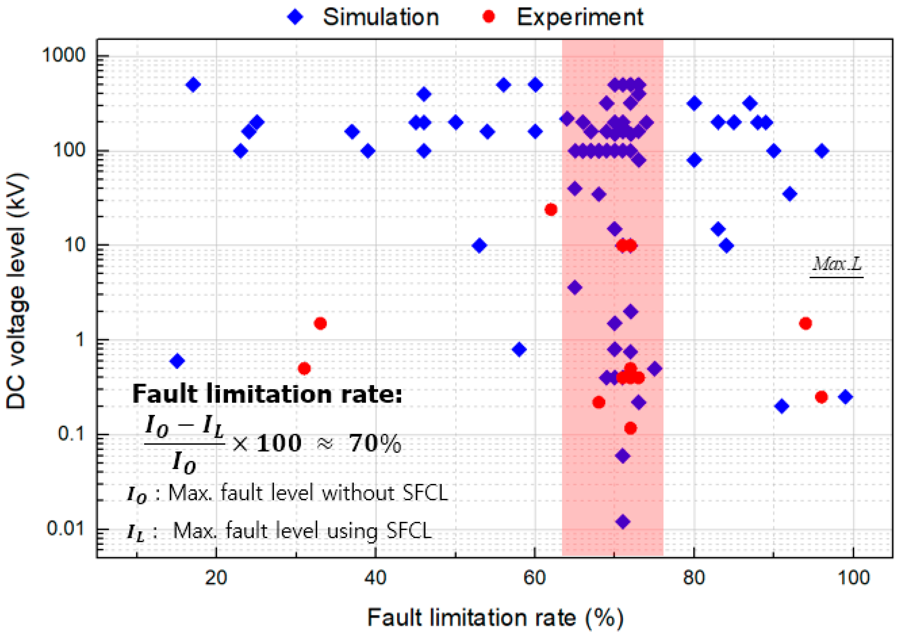
In order to experimentally analyze the combined system of a SI-SFCL and a DCCB, two protective devices were designed and manufactured as described in Section 2 and Section 3, respectively. For the voltage and current of the model DC power system for this study, a DC system of 500 V and 50 A was selected by referring to the power environment of the laboratory and the rating of a commercial DCCB. In order to set the design goal for the fault current limiting rate of the SI-SFCL, previous studies were investigated as shown in Figure 2, and the fault current limiting rate was selected as 70%. The SI-SFCL design was performed based on the maximum fault current of the point-to-point VSC-based HVDC system, excluding external influences on internal faults. The maximum fault current of the VSC-based HVDC was caused by a short-circuit fault on the DC side as shown in Figure 3a. The most important factor affecting the magnitude and duration of the fault current is the capacitance value of the DC link capacitor. The capacitor was selected by referring to the design criteria in [35], and the maximum fault current of the model system was 500 A. The fault current simulation result is shown in Figure 3b.
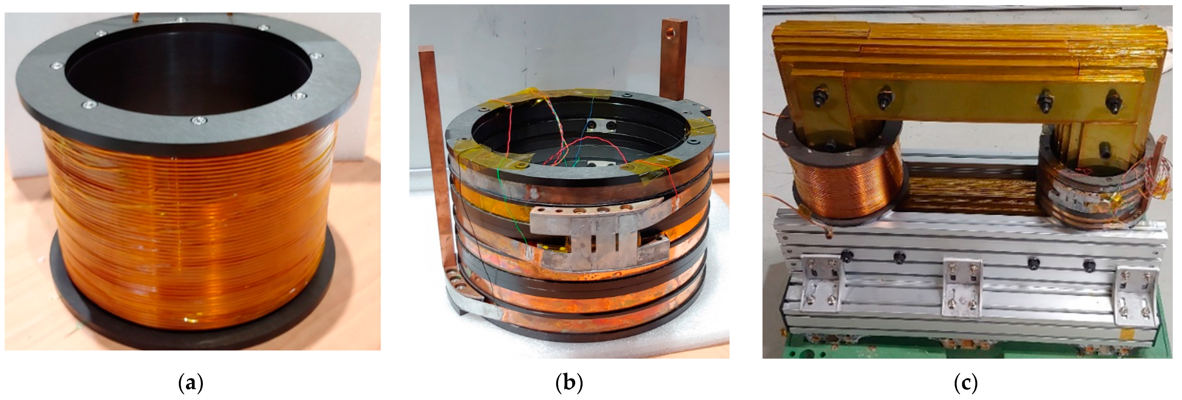
The detailed design of the SI-SFCL covered in this session was performed in the author’s previous work [36,37]. The SI-SFCL has a structure similar to that of a single-phase transformer as described in Section 2.1. The cross-section of the iron core was constructed by stacking thin steel plates close to a circle to reduce magnetic flux leakage. The material of the iron core was non-oriented silicon steel (M-36). The PW was a copper coil and connected in series to the DC system. The SW was a superconducting coil made of high-temperature superconducting (HTS) wire and had a separate power supply to create a magnetic field. The main specifications of the designed SI-SFCL are presented in Table 1 and the fabricated SI-SFCL is shown in Figure 4, respectively.

2.4. Independent Performance Test Results of the SI-SFCL

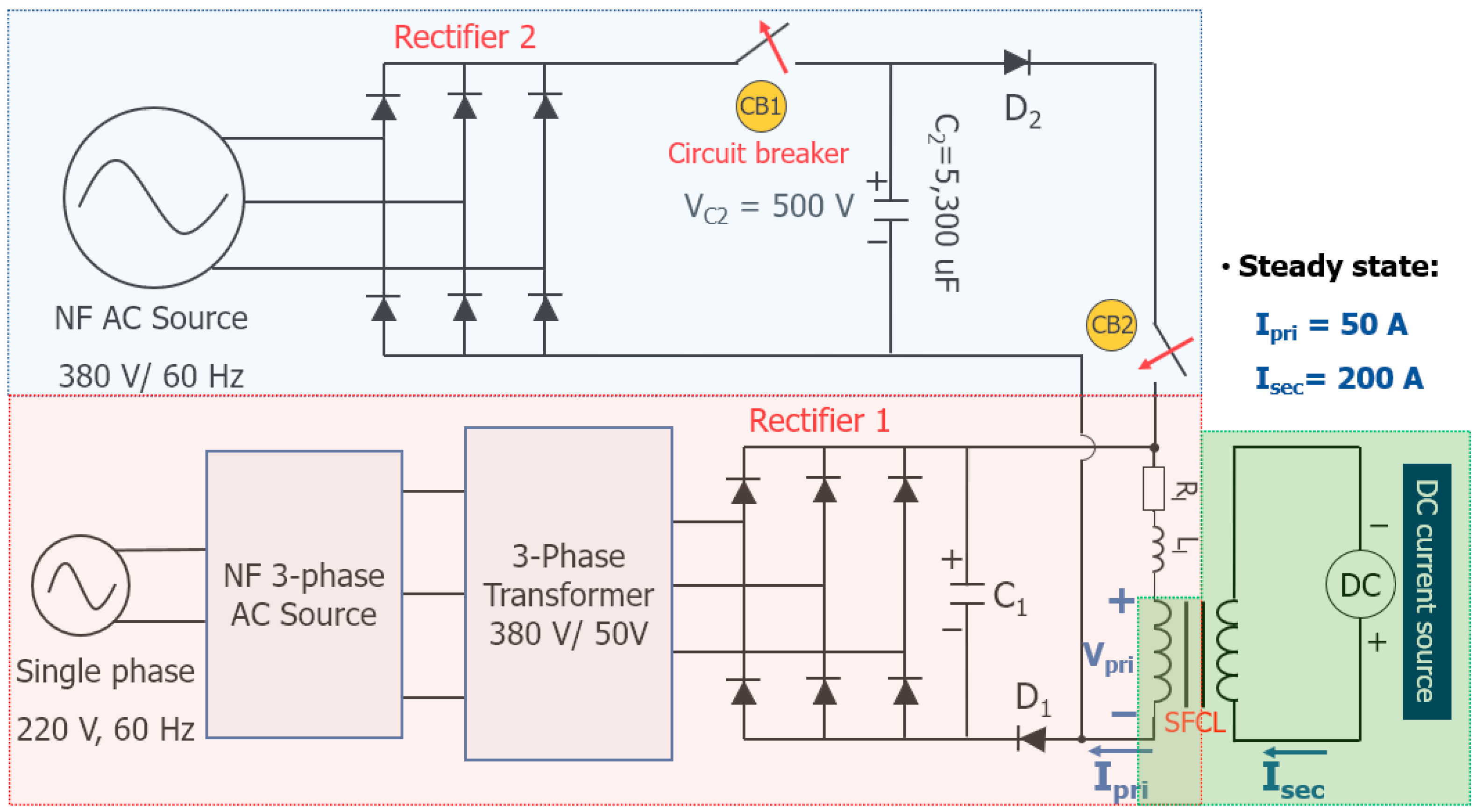
In order to verify the performance and operation characteristics of the manufactured SI-SFCL, an independent operation test of the SI-SFCL was performed excluding other protective equipment. To generate the fault current of the target system shown in Figure 2, the test circuit was configured as shown in Figure 5. The test circuit replaced the IGBT for the VSC with a diode and did not include the operating control of the converter. However, it was an equivalent circuit that could test the short-circuit fault in a VSC-based HVDC system.
The circuit in the red box in Figure 5 is the circuit that simulates steady-state operation (hereafter Rectifier 1). Rectifier 1 circuit was supplied with 3-phase AC power, generated DC voltage through full-wave rectifier diode, and had line constants R1 and L1. The circuit supplied 50 A of line current to the PW of SI-SFCL in steady-state. The circuit for SI-SFCL operation is shown in the green-colored box in Figure 5. The PW and SW of the SI-SFCL were electrically insulated like a transformer and were magnetically coupled. The SW was connected with a separate DC source to create a constant magnetic field. The Rectifier 2 circuit shown in blue box in Figure 5 is a circuit for generating the fault current. Before the fault current test, CB1 must be closed and CB2 opened to charge the capacitor C2 voltage up to 500 V. When the voltage charging was completed, CB1 was also opened to maintain the voltage of C2. When the Rectifier 1 circuit and the SI-SFCL became steady-state and the measuring device was ready, CB2 was closed to discharge the energy that was charged in C2 and generate a fault current. The fault current passed through the PW of the SI-SFCL and the SI-SFCL performed the operation described in Section 2.1. The voltage and current of the PW ( V p r i , I p r i ) and the current of the SW ( I s e c ) were measured to confirm the fault current limiting performance and operation characteristics of the SI-SFCL.
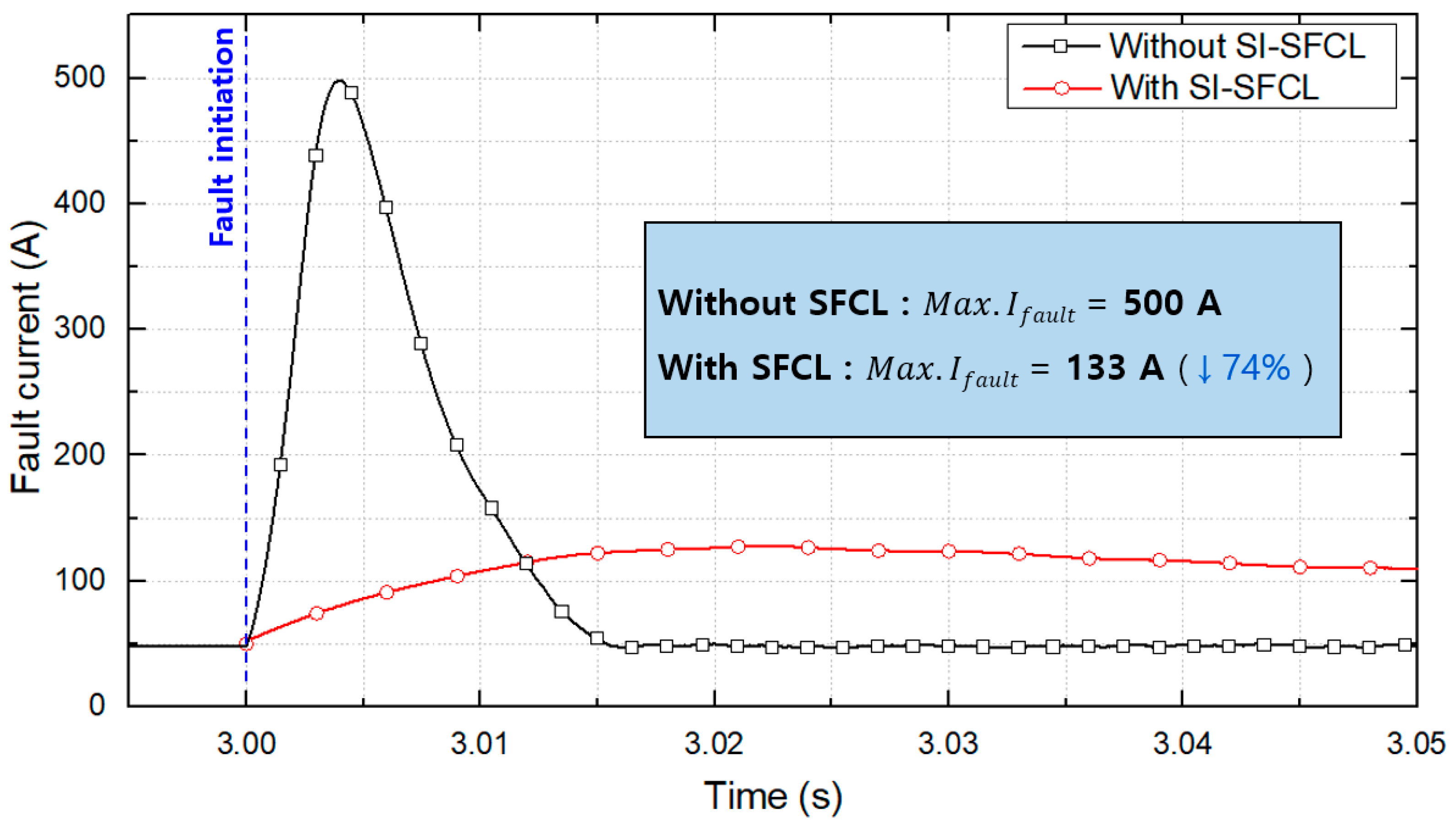
The DC fault experiments were performed with and without the SI-SFCL, respectively. The performance and effect of the manufactured SI-SFCL were confirmed by comparing two results. Figure 6 shows the graph of the fault current test result. In the without-SFCL condition, the maximum fault current was about 500 A and reached its peak 4 ms after the fault occurs. On the other hand, when the SI-SFCL was included, the maximum fault current was 133 A, and it can be seen that the fault current was reduced by 74%. In the circuit without SI-SFCL, the energy stress due to capacitor discharge was dissipated over about 15 ms. However, the circuit including the SI-SFCL had almost the same resistance value, but the energy stress dissipation took longer because the inductance of the SI-SFCL increases the time constant.
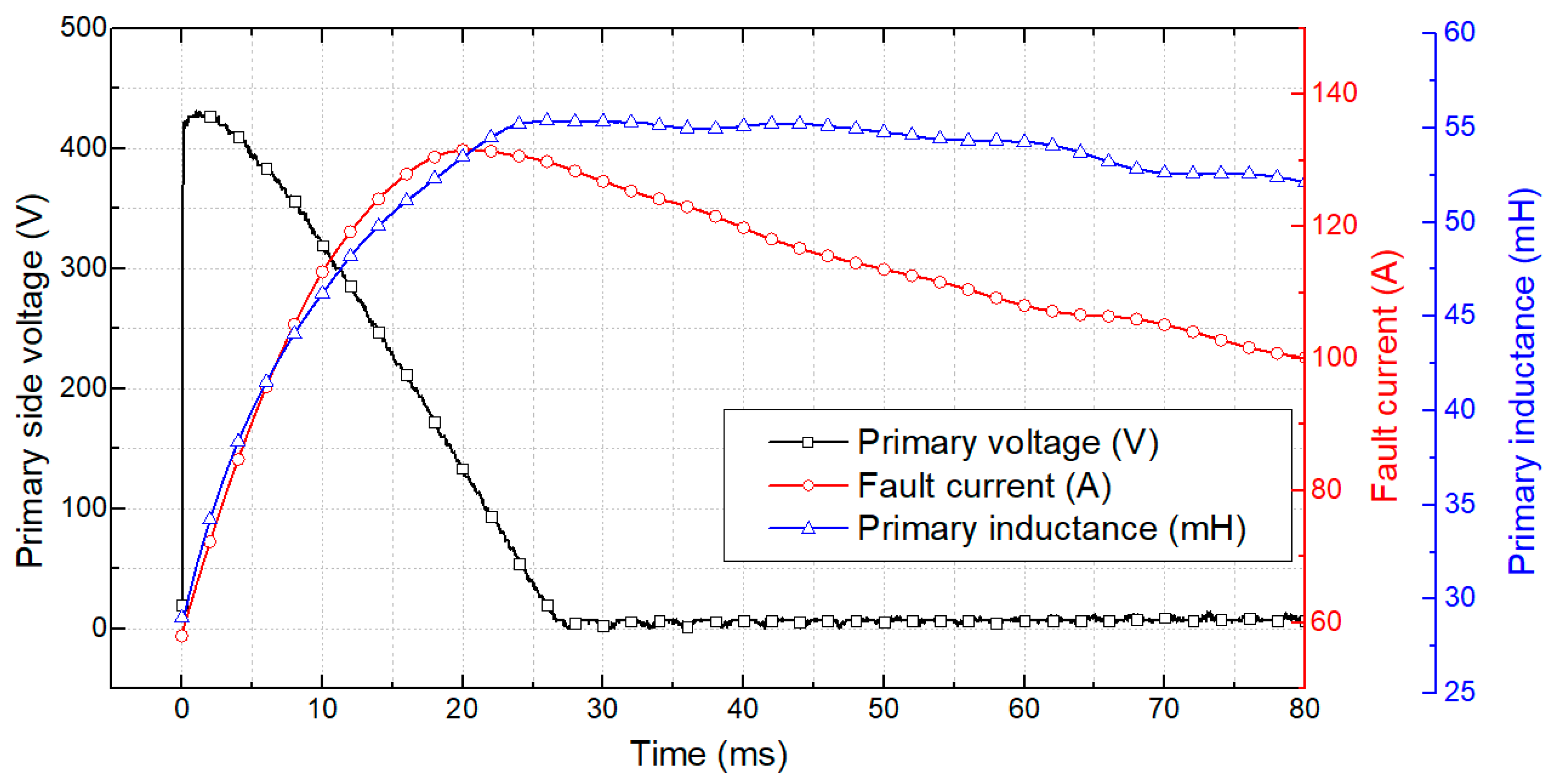
Figure 7 shows the voltage and current of the PW measured in the experiment and the inductance of the SI-SFCL calculated by Equation (6). In a steady state, the inductance of the PW is 28 mH. When a fault occurs in the test circuit, the current flowing through the PW increased, the saturation of the iron core was eliminated, and the inductance rapidly increased to 56 mH. As shown in Figure 7, the current-limiting operation of the SI-SFCL was performed by increasing the inductance of the transmission line. The increased inductance not only limited the fault current, but also increased the capacitor discharge time. In the case of VSC-based HVDC, after capacitor-discharge, current flowed through the free-wheel-diode and damaged the converter. An increase in the discharge time means that a margin can be given to the protection equipment.

3. Construction and Design of a Mechanical DC Circuit Breaker

The mechanical DCCBs consist of three parallel connections: a mechanical interrupter (steady-state current path), a current commutation circuit necessary to create an artificial zero-crossing through the mechanical interrupter, and an energy absorber such as a metal oxide surge arrester. In this paper, the PR type was selected among the methods for generating the mechanical DCCB artificial current zero-crossing point.
Figure 8 simply shows the configuration of a PR type CB and the fault-interruption waveform. For the mechanical DCCB, a commercial molded case DCCB(BK63H) with a rating of 63 A from LSIS company was used. The BK63H had a class C trip curve and immediately performed a breaking operation when 7.5 times the rated current flowed. The trip signal was generated by a thermal-magnetic method using bimetal. The PR type connected the passive elements L and C in series and was connected in parallel with mechanical CB. According to the passive-resonance frequency ( f L C ) calculated by Equations (7)–(9), series resonance occurred, and a vibration current was generated [38,39].
Z L C = L C   [ Ω ]
I D C = U D C Z L C   [ A ]
f L C = 1 2 π L C   [ H z ]
The experiments were performed in various frequency bands to find the LC resonance condition with a short cut-off time for the target system. The frequency, which is a variable, was selected as 285, 500, 1000, 1500, and 2000 Hz. At this time, the reactor was fixed at 55 μH and the frequency was adjusted by changing the capacitance value. Table 2 shows the cut-off time according to the frequency change.
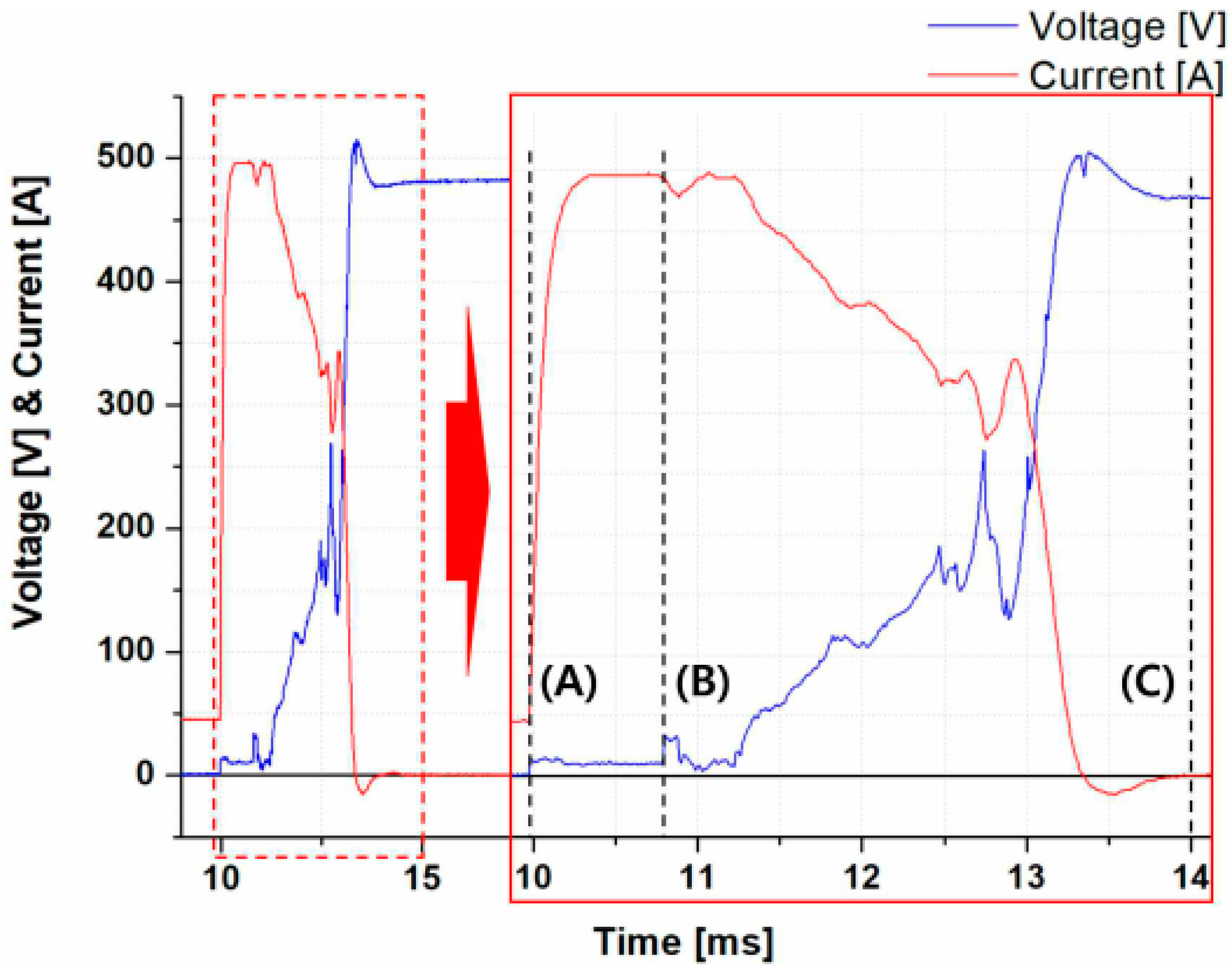
Finally, the resonance circuit was selected as a combination of L and C representing a frequency of 1500 Hz. The selected DCCB had a blocking time of 4 ms, and the test results are shown in Figure 9. Figure 9 shows the fault current and the voltage measured across the CB. In the figure, (A) is the time when a fault occurred, (B) is the time when the DCCB started to open, and (C) is the time when all breaking operations were completed. From the graph, the opening starts of CB at about 0.8 ms after a fault and it takes 3.2 ms to interrupt the fault after opening.

4. Construction and Testing of a Protection System Combining a SI-SFCL and a DCCB

4.1. Experimental Circuit Configuration and the Testing Process

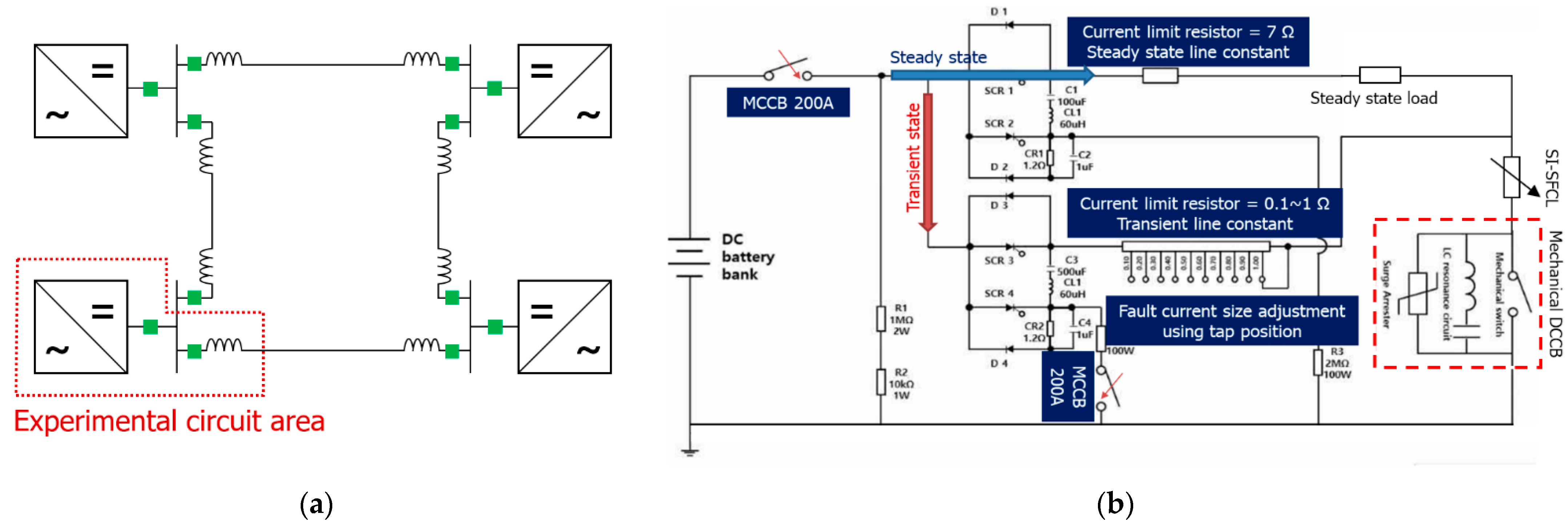
In order to perform the experiment of a DCCB combined with a SI-SFCL, a four-terminal MTDC topology suitable for the application of the corresponding protection facility was selected. The four-terminal MTDC is a representative HVDC network configuration and has practical installation cases such as the Zhangbei dc grid project in China [40]. In the lab-scale experiment, since all four terminals could not be implemented, one terminal was mainly expressed, but a lead-acid battery was used to realize a larger amount of energy. Figure 10 shows the target system and experimental circuit.

4.2. Experimental Circuit Configuration and the Testing Process

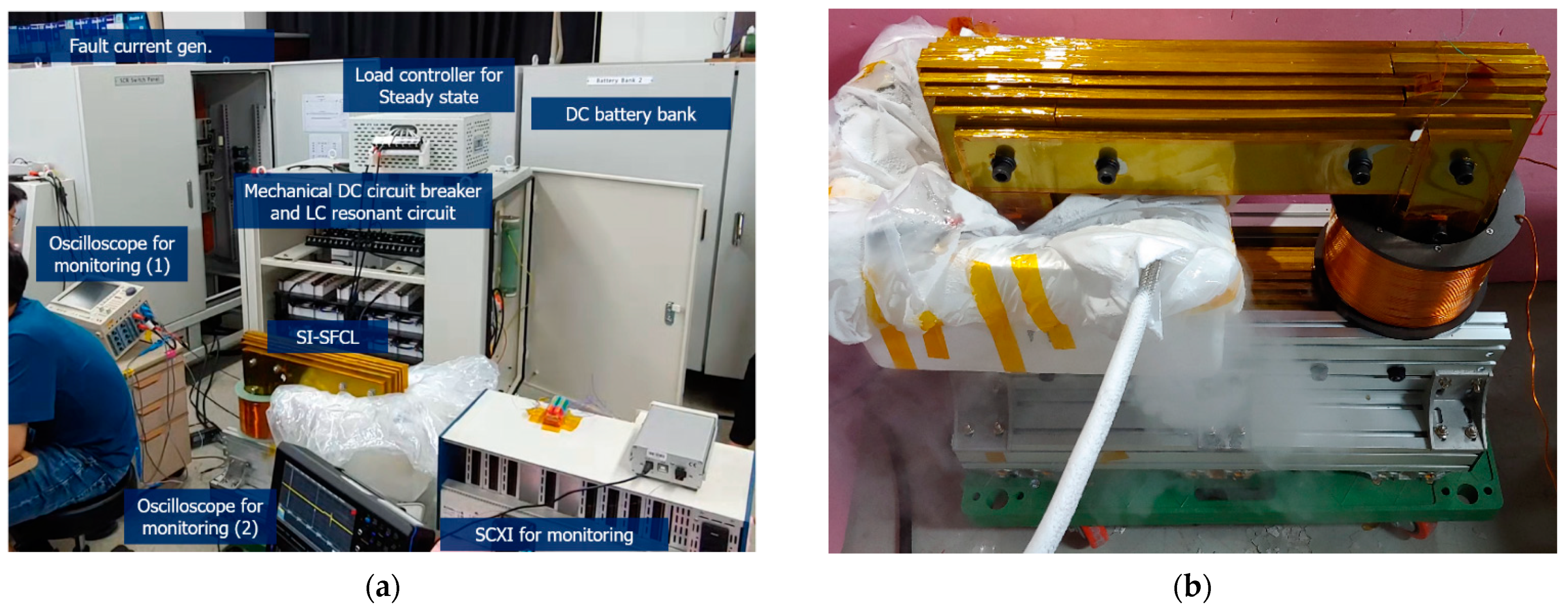
An experimental circuit was constructed to analyze the characteristics of a system using a SI-SFCL and a DCCB together. Figure 10b is a circuit diagram of a fault generator connected to the DC power supply and was produced to analyze the breaking operation characteristics of the SI-SFCL and the mechanical DCCB. The DC power supply consisted of 150 AH 12 V lead-acid batteries, and a total of 63 units were connected in series. It was used as a DC power supply that could output up to about 800 V. The MCCB 200 A breaker connected to the DC power supply was the backup CB according to the fault of the breaking operation of the DCCB under test, and its minimum operating time is 60 ms after fault inception. The circuit was composed of two routes to form a closed circuit and was classified into a steady-state circuit and a transient circuit according to the size of each load. In the experimental circuit, it was possible to set the steady-state load to about 10~46.8 Ω and the transient load to about 1~0.1 Ω. The steady-state load was set to 10 Ω, the transient state load was set to 1 Ω, and the experiment was performed according to the rated capacity. The SI-SFCL is coupled in series in front of a mechanical DC breaker. The SW was cooled separately to liquid nitrogen temperature (77 K) using a cooling bath as shown in Figure 11b. The configuration of the actual experimental system is shown in Figure 11 and Figure 12.

4.3. Experimental Results and Analysis

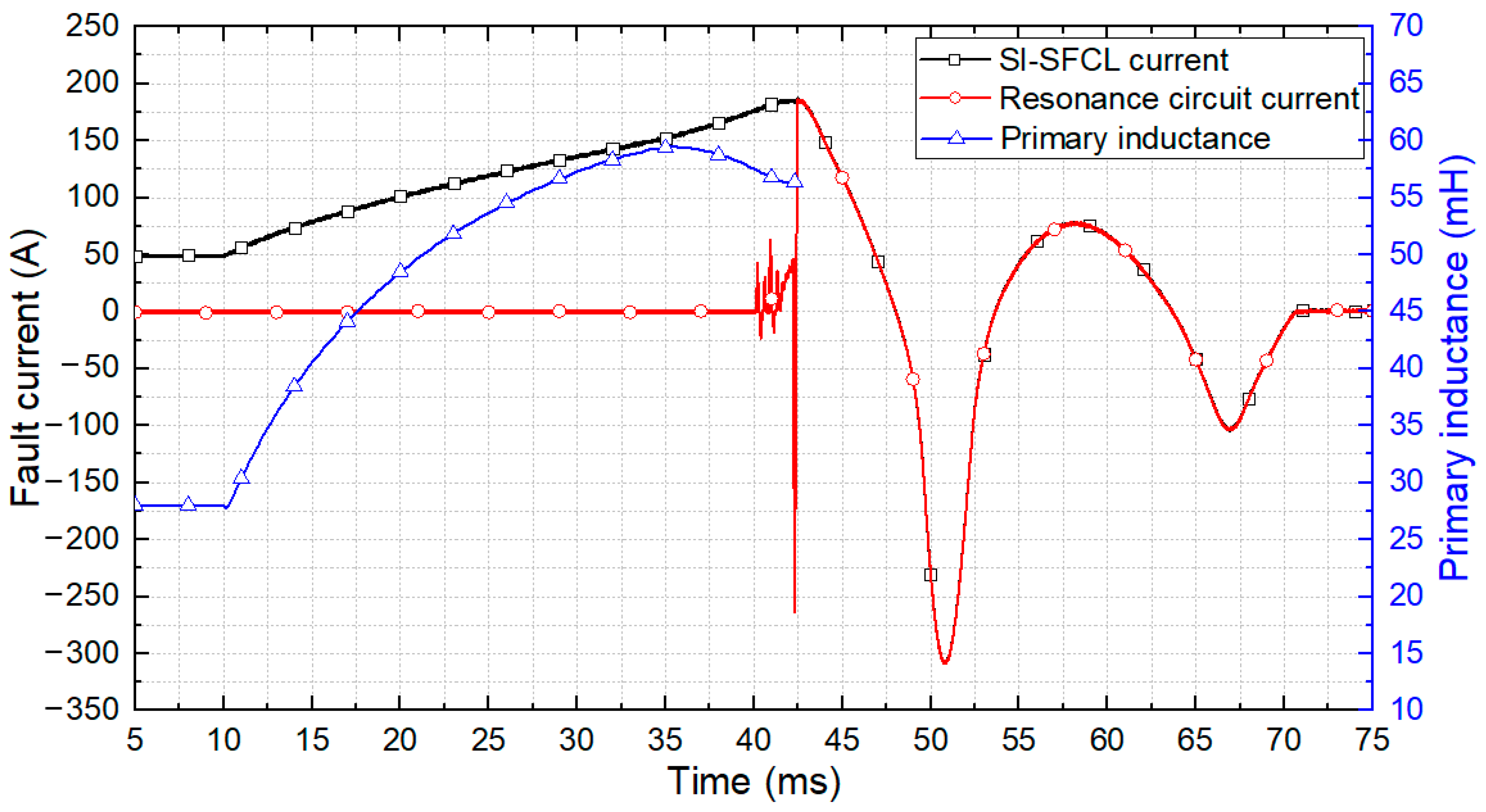
Figure 13 shows the experimental results. The fault was initiated at 10 ms. A steady-state current of 50 A flowed in the DC line before the fault. A fault occurred at 10 ms and the fault current increased from 50 A to the maximum current at an average rate of 4 A/ms. At the beginning of the fault, the fault current graph was convex upward, indicating that the inductance gradually increased. The increase continued, and at 150 A, the graph of the fault current became convex downward and increased steeply. At 37.5 ms, the DCCB opened and a current flowed in the resonance circuit. At 42.5 ms, the DCCB was fully opened, the residual energy was absorbed through the arrester, and blocking completed at 71 ms. The inductance was calculated using Equation (6). The primary inductance of the SI-SFCL had a value of 28 mH in the steady-state. After the fault, the inductance increased to 59 mH for 35 ms. After that, the primary side current value continued to increase, but the inductance decreased. At this point, it could be seen that the primary side iron core was saturated in the reverse direction. The inductance was calculated up to the complete opening time of the DCCB. From the DCCB point of view, it took 30 ms from the fault to the opening, 2.5 ms from the opening to the arc extinguishing, and 28.5 ms from the extinguishing to the fault clearing, and the total time required was 61 ms.

5. Suggestion of a Fault Current Detection Scheme to Improve the Protection Coordination with a SI-SFCL

An experiment was performed on the fault cut-off in a DC circuit including a SI-SFCL and a mechanical DCCB, and the experimental results are shown in Figure 13. The results were compared with the case shown in Figure 9 in which the mechanical DCCB was used alone. The main difference between both results is the time taken for the DCCB to detect a fault and open the breaker. In this experiment, the DCCB was not equipped with a separate fault detection device such as a relay and only operated by the thermal-magnetic method of a mechanical CB. The thermal-magnetic method is a method of operating a CB by heating a bimetal element by energy above a certain level [41]. When using the DCCB alone, the DCCB operated in 0.8 ms, but when using the SI-SFCL together, it took about 30 ms to operate the DCCB. This time difference means that when a SI-SFCL is used together, the pick-up time of a DCCB is delayed. This time delay occurs because the increased inductance at the PW of the SI-SFCL limits the magnitude and rate of increase in the fault current. The limited fault current reduces the capacity of the DCCB, but as the interrupting time is delayed, the energy that the surge arrester must absorb increases. In the experiment, the interrupting time delay resulted in a high resonant current of −300 A, which exceeded the surge arrester rating. In addition, to operate the DC system stably, fast detection and selective isolation of faults and rapid recovery after fault clearing are essential. Therefore, the delayed fault interruption is a detrimental factor for system operation. To solve these problems, a suitable protection coordination should be established.
In particular, in the case of applications with dynamic characteristics, such as SI-SFCL, a more careful approach considering the characteristic change is required for protection coordination. If an unsuitable protection strategy is established without considering these aspects, unexpected malfunctions or side effects may occur. The experiment performed in this paper detected a fault based on the fault current magnitude and thermal energy, but there was a side effect of delaying the interrupting time due to the fault current limitation of the SI-SFCL. Such problems can be solved by establishing suitable protection coordination. In order to supplement the experimental results, an internal fault detection strategy suitable for MTDC systems including a SI-SFCL was established. First, the fault detection technique used in the existing DC system was investigated and shown in Table 3.
The 8 fault detection methods listed in Table 3 are the most popular fault detection techniques for DC systems. In practice, several methods are combined to complement each other when establishing a protection strategy. The target MTDC system of this paper assumes that the existing DC reactor for FCL has been replaced with a SI-SFCL. In Table 3, the two methods utilizing communication can pick up faults without relying on the reactor [42]. However, it was excluded from the major fault detection methods because there is a constraints by the usage environment and the operation time is slower than the non-unit protection strategy that does not use communication [7]. In order to establish a suitable non-unit fault detection strategy for the combination of a SI-SFCL and a mechanical DCCB, the authors considered two important conditions as follows:
  • Fast fault detection is required to compensate for the slow operation of the DCCB;
  • It should not be affected by the line constant changed by the SI-SFCL operation.
The SI-SFCL limits the fault current by reducing the increasing rate of the fault current. These mechanisms directly affect the fault detection method with current-related (Overcurrent and ROCOC) thresholds. In order to overcome this effect and achieve the first condition, the threshold value and margin must be lowered, which increases the probability of malfunction and reduces reliability. Therefore, neither method is suitable.
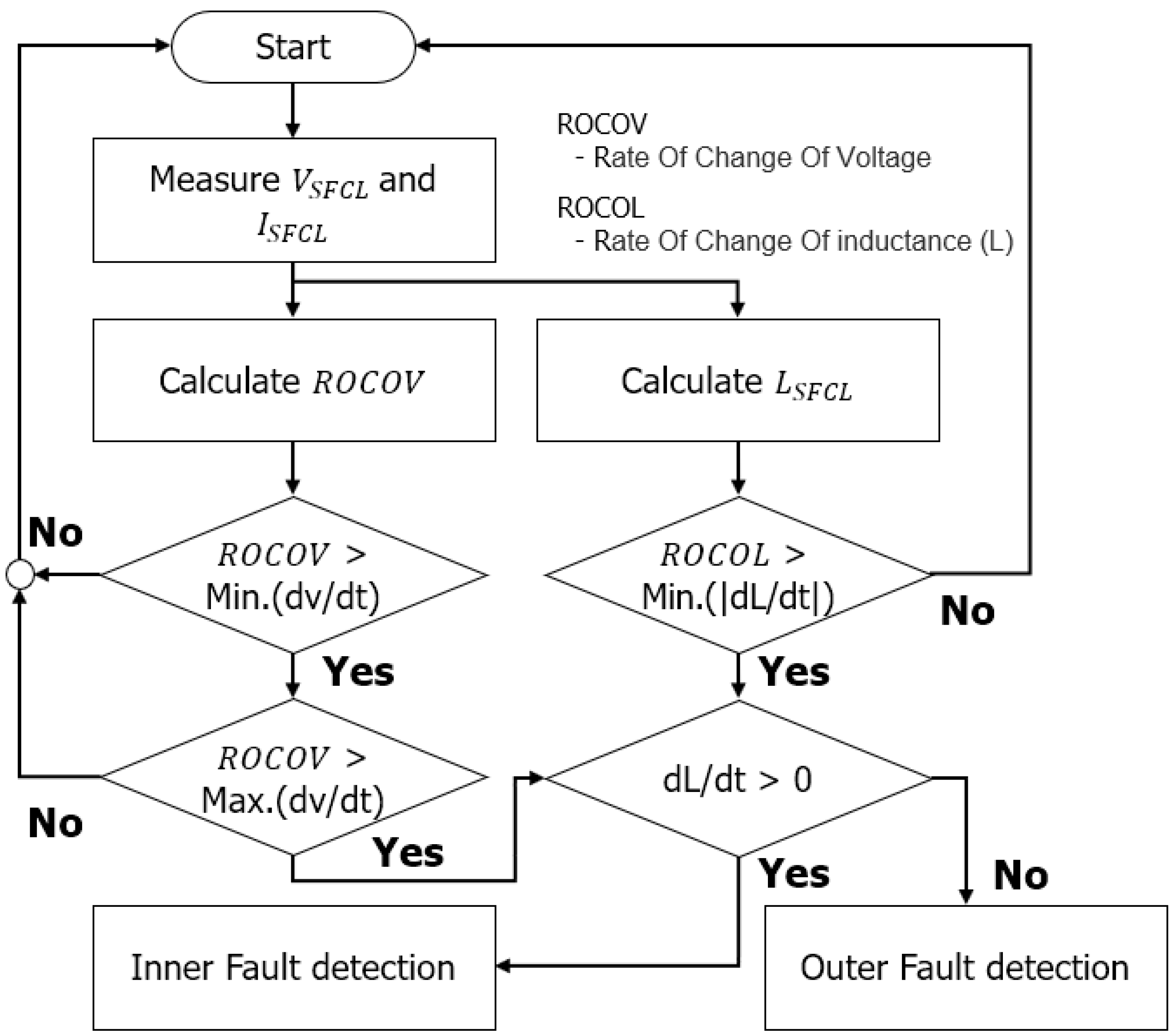
Regarding the second condition, traveling waves or wavelet transform methods are not suitable because accurate results cannot be obtained due to changing impedance. As a result, among the methods in Table 3, the most suitable method as the main protection strategy is the ROCOV method using the rate of change of voltage. As shown in Figure 3b, when a ground fault or short circuit fault occurs, the voltage changes significantly. The voltage variations are so pronounced that the effect of changes in the inductance of the SI-SFCL is easily overcome. However, if only the ROCOV method is used, it is relatively weak in distinguishing long-distance fault or fault occurring near the bus. In order to mitigate such a problem, a protection process as shown in Figure 14 was suggested by combining the characteristics of the ROCOV and the SI-SFCL. Unlike the air-core DC reactor used as FCL, the SI-SFCL has a directionality due to iron-core saturation. If the two factors of inductance change threshold and iron core saturation directionality are applied together, the protection strategy can achieve both sensitivity and selectivity.
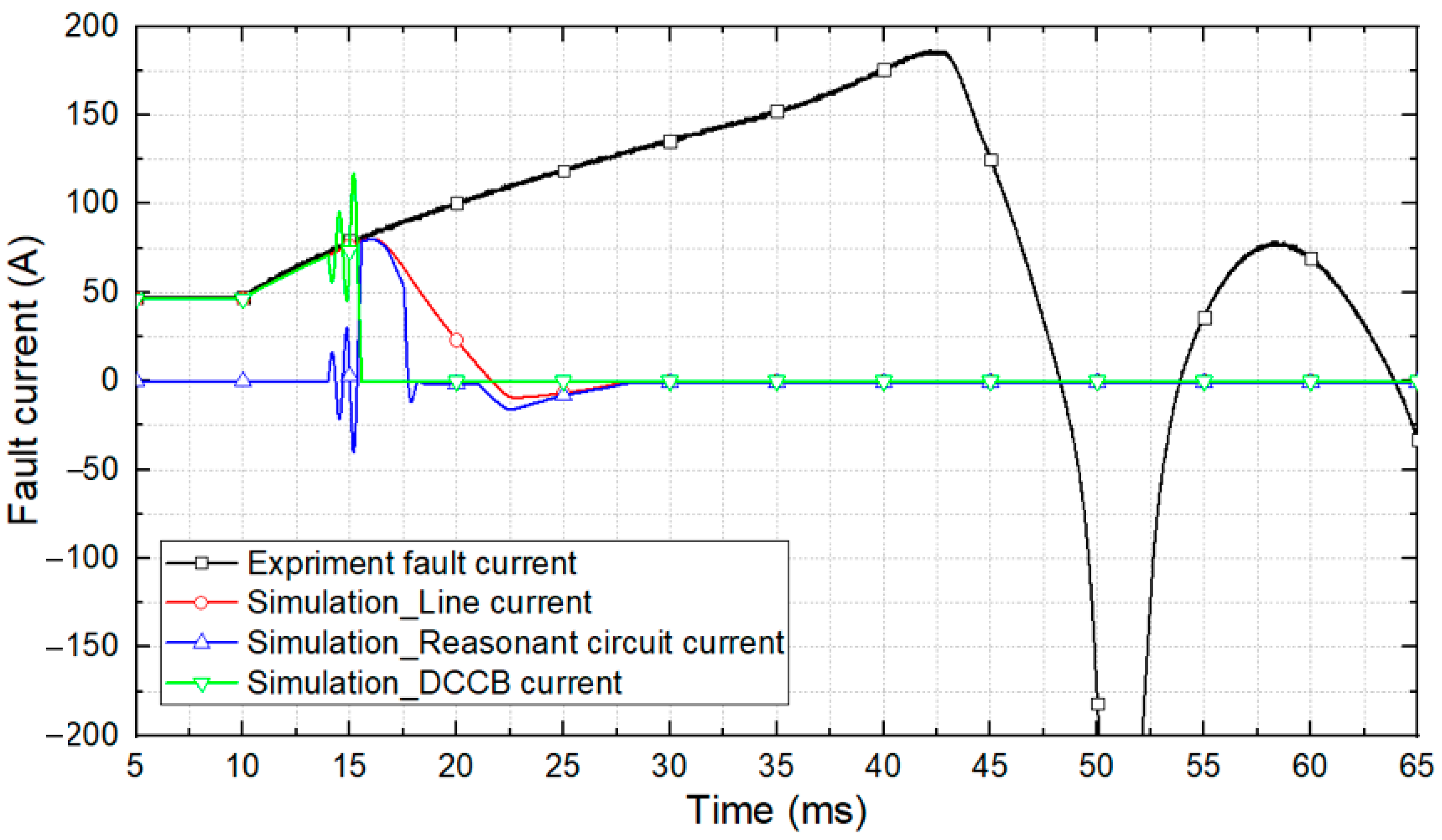
The simulation was performed by applying the fault current detection strategy shown in Figure 14 through the PSCAD program. A simulation circuit including a DCCB and a SI-SFCL was configured in the same way as in the experiment. Figure 15 shows the simulation results and experimental results for comparison.
As a result of the simulation, the DCCB opened at about 3.5 ms, and the fault current at that point was 73 A. Additionally, since the fault current at the time of detection was reduced, the resonance circuit generated a faster zero point. The circuit breaker fully opened at 5 ms, after which the residual energy was dissipated. In summary, when the circuit breaker was operated through the fault current detection, all blocking operations were completed about 18 ms after the occurrence of the fault, and the effect of shortening the existing result by more than 40 ms was confirmed. Through this, it was confirmed that the proposed fault current detection method is suitable for the SI-SFCL and can perform fast interruption.

6. Conclusions

In this paper, a protection system combining an SI-SFCL and a mechanical CB that can be applied to MTDC grid systems was constructed and the fault current limiting and interrupting characteristics were experimentally analyzed. In order to evaluate the transient characteristics and performance of the SI-SFCL, a method for mathematically calculating the dynamic behavior of inductance was proposed and applied. A lab-scale 500 V, 50 A DC system was fabricated as a model system, and the fault current of the system was set to 500 A. A DC circuit breaker with an appropriate rated capacity was designed and manufactured to conduct an interrupting test against fault in combination with an SI-SFCL, and the interaction effect of the SI-SFCL on a mechanical CB was verified through the experiment. Through the experiment, it was verified that the limiting of the fault current can reduce the CB capacity, but the fault pick-up time was delayed by the SI-SFCL. Thus, we presented a mitigating solution suitable for DC interrupting circuits including SI-SFCL by analyzing the fault current detection delay that occurred during the experiment. The validity of the proposed fault detection method was verified by applying it to a simulation circuit reflecting the experimental system. As a result, the DCCB opening was made within 3.5 ms, and the total fault clearing time was also reduced by about 40 ms compared with the experimental result. These results are sure to be helpful in establishing the protection coordination strategy of the DCCB and SI-SFCL when applying an actual SI-SFCL to the DC systems.

Author Contributions

Conceptualization, methodology, investigation, experiment, writing—original draft preparation, J.-I.L.; conceptualization, methodology, experiment, V.Q.D. and C.S.K.; writing—review and editing, project administration, M.-C.D. and S.-j.L., supervision, M.P. All authors have read and agreed to the published version of the manuscript.

Funding

This research was supported by Korea Electrotechnology Research Institute (KERI) Primary research program through the National Research Council of Science & Technology (NST) funded by the Ministry of Science and ICT (MSIT).

Institutional Review Board Statement

Not applicable.

Informed Consent Statement

Not applicable.

Data Availability Statement

Not applicable.

Conflicts of Interest

The authors declare no conflict of interest. The funders had no role in the design of the study.

References

  1. Alassi, A.; Bañales, S.; Ellabban, O.; Adam, G.; MacIver, C. HVDC transmission: Technology review, market trends and future outlook. Renew. Sustain. Energy Rev. 2019, 112, 530–554. [Google Scholar] [CrossRef]
  2. Meah, K.; Ula, S. Comparative evaluation of HVDC and HVAC transmission systems. In Proceedings of the 2007 IEEE Power Engineering Society General Meeting, Tampa, FL, USA, 24–28 June 2007; IEEE: Tampa, FL, USA, 2007; pp. 1–5. [Google Scholar]
  3. Flourentzou, N.; Agelidis, V.G.; Demetriades, G.D. VSC-based HVDC power transmission systems: An overview. IEEE Trans. Power Electron. 2009, 24, 592–602. [Google Scholar] [CrossRef]
  4. Candelaria, J.; Park, J.D. VSC-HVDC system protection: A review of current methods. In Proceedings of the 2011 IEEE/PES Power Systems Conference and Exposition, Phoenix, AZ, USA, 20–23 March 2011; IEEE: Phoenix, AZ, USA, 2011; pp. 1–7. [Google Scholar]
  5. Ong, C.M.; Hamzei-Nejad, A. A general-purpose multiterminal DC load-flow. IEEE Trans. Power Appar. Syst. 1981, PAS-100, 3166–3174. [Google Scholar] [CrossRef]
  6. Fudeh, H.; Ong, C.M. A simple and efficient AC-DC load-flow method for multiterminal DC systems. IEEE Trans. Power Appar. Syst. 1981, PAS-100, 4389–4396. [Google Scholar] [CrossRef]
  7. Leterme, W.; Van Hertem, D. Classification of Fault Clearing Strategies for HVDC Grids; CIGRE: Lund, Sweden, 2015. [Google Scholar]
  8. Yang, J.; Fletcher, J.E.; O’Reilly, J. Short-circuit and ground fault analyses and location in VSC-based DC network cables. IEEE Trans. Ind. Electron. 2011, 59, 3827–3837. [Google Scholar] [CrossRef] [Green Version]
  9. Liu, Z.; Mirhosseini, S.S.; Popov, M.; Audichya, Y.; Colangelo, D.; Jamali, S.; Palensky, P.; Hu, W.; Chen, Z. Protection Testing for Multiterminal High-Voltage dc Grid: Procedures and Procedures and Assessment. IEEE Ind. Electron. Mag. 2020, 14, 46–64. [Google Scholar]
  10. Tahata, K.; El Oukaili, S.; Kamei, K.; Yoshida, D.; Kono, Y.; Yamamoto, R.; Ito, H. HVDC circuit breakers for HVDC grid applications. In Proceedings of the 11th IET International Conference on AC and DC Power Transmission, Birmingham, UK, 10–12 February 2015; IET: Birmingham, UK, 2015; pp. 1–9. [Google Scholar]
  11. Mokhberdoran, A.; Carvalho, A.; Leite, H.; Silva, N. A review on HVDC circuit breakers. In Proceedings of the 3rd Renewable Power Generation Conference (RPG 2014), Naples, Italy, 24–25 September 2014; IET: Naples, Italy, 2014; pp. 1–6. [Google Scholar]
  12. Franck, C.M. HVDC circuit breakers: A review identifying future research needs. IEEE Trans. Power Deliv. 2011, 26, 998–1007. [Google Scholar] [CrossRef] [Green Version]
  13. Xin, Y.; Gong, W.Z.; Hong, H.; Gao, Y.Q.; Niu1, X.Y.; Zhang, J.Y.; Sun, Y.W.; Ren, A.L.; Wang, H.Z.; Zhang, L.F.; et al. Development of 220 kV/300 MVA superconductive fault current limiter. Supercond. Sci. Technol. 2007, 25, 105011. [Google Scholar] [CrossRef]
  14. Eckroad, S. Superconducting Power Equipment—Technology Watch; Electric Power Research Institute: Palo Alto, CA, USA, 2012. [Google Scholar]
  15. Noe, M.; Steurer, M. High-temperature superconductor fault current limiters: Concepts applications and development status. Supercond. Sci. Technol. 2007, 20, R15–R29. [Google Scholar] [CrossRef]
  16. Kim, H.R.; Yang, S.E.; Yu, S.D.; Kim, H.; Park, B.J.; Han, Y.H.; Yu, J. Development and grid operation of superconducting fault current limiters in KEPCO. IEEE Trans. Appl. Supercond. 2014, 24, 1–4. [Google Scholar]
  17. Jin, J.X.; Tang, Y.J.; Xiao, X.Y.; Du, B.X.; Wang, Q.L.; Wang, J.H.; Zhu, J.G. HTS power devices and systems: Principles, characteristics, performance, and efficiency. IEEE Trans. Appl. Supercond. 2016, 26, 1–26. [Google Scholar] [CrossRef]
  18. Chen, L.; Chen, H.; Shu, Z.; Zhang, G.; Xia, T.; Ren, L. Comparison of inductive and resistive SFCL to robustness improvement of a VSC-HVDC system with wind plants against DC fault. IEEE Trans. Appl. Supercond. 2016, 26, 1–8. [Google Scholar] [CrossRef]
  19. Lee, S.R.; Ko, E.Y.; Lee, J.J.; Dinh, M.C. Development and HIL Testing of a Protection System for the Application of 154-kV SFCL in South Korea. IEEE Trans. Appl. Supercond. 2019, 29, 1–4. [Google Scholar] [CrossRef]
  20. Barzegar-Bafrooei, M.R.; Foroud, A.A.; Ashkezari, J.D.; Niasati, M. On the advance of SFCL: A comprehensive review. IET Gener. Transm. Distrib. 2019, 13, 3745–3759. [Google Scholar] [CrossRef]
  21. Yazdani-Asrami, M.; Staines, M.; Sidorov, G.; Davies, M.; Bailey, J.; Allpress, N.; Gholamian, S.A. Fault current limiting HTS transformer with extended fault withstand time. Supercond. Sci. Technol. 2019, 32, 035006. [Google Scholar] [CrossRef]
  22. Yazdani-Asrami, M.; Staines, M.; Sidorov, G.; Eicher, A. Heat transfer and recovery performance enhancement of metal and superconducting tapes under high current pulses for improving fault current-limiting behavior of HTS transformers. Supercond. Sci. Technol. 2020, 33, 095014. [Google Scholar] [CrossRef]
  23. Song, W.; Pei, X.; Xi, J.; Zeng, X. A novel helical superconducting fault current limiter for electric propulsion aircraft. IEEE Trans. Transp. Electrif. 2020, 7, 276–286. [Google Scholar] [CrossRef]
  24. Lee, J.G.; Khan, U.A.; Lee, H.Y.; Lee, B.W. Impact of SFCL on the four types of HVDC circuit breakers by simulation. IEEE Trans. Appl. Supercond. 2016, 26, 1–6. [Google Scholar] [CrossRef]
  25. Garcia, W.R.L.; Tixador, P.; Raison, B.; Bertinato, A.; Luscan, B.; Creusot, C. Technical and economic analysis of the R-type SFCL for HVDC grids protection. IEEE Trans. Appl. Supercond. 2017, 27, 1–9. [Google Scholar] [CrossRef]
  26. Jiang, Z.; Yu, Z. Analysis of the MTDC System Protection Strategy based on Resistive DC SFCL. In Proceedings of the 2020 IEEE International Conference on Applied Superconductivity and Electromagnetic Devices (ASEMD), Tianjin, China, 16–18 October 2020; IEEE: Tianjin, China, 2020; pp. 1–2. [Google Scholar]
  27. Garcia, W.L.; Bertinato, A.; Tixador, P.; Raison, B.; Luscan, B. Full-selective protection strategy for MTDC grids based on R-type superconducting FCLs and mechanical DC circuit breakers. In Proceedings of the 5th IET International Conference on Renewable Power Generation (RPG), London, UK, 21–23 September 2016; IET: London, UK, 2016; pp. 1–7. [Google Scholar]
  28. Rahman, M.H.; Xu, L.; Yao, L. Protection of large partitioned MTDC networks using DC-DC converters and circuit breakers. Prot. Control. Mod. Power Syst. 2016, 1, 1–9. [Google Scholar] [CrossRef] [Green Version]
  29. Chang, B.; Cwikowski, O.; Pei, X.; Barnes, M. Impact of fault current limiter on VSC-HVDC dc protection. In Proceedings of the 12th IET International Conference on AC and DC Power Transmission (ACDC 2016), Beijing, China, 28–29 May 2016; pp. 1–6. [Google Scholar]
  30. Li, B.; Jing, F.; Li, B.; Wen, W. Research on the parameter matching between active SI-SFCL and DC circuit breaker in DC systems. IEEE Trans. Appl. Supercond. 2019, 29, 1–5. [Google Scholar] [CrossRef]
  31. Li, B.; Jing, F.; Li, B.; Chen, L. Research of the application of active saturated iron-core superconductive fault current limiters in the VSCHVDC system. IEEE Trans. Appl. Supercond. 2018, 28, 5602906. [Google Scholar] [CrossRef]
  32. Li, B.T.; Jia, J.F.; Li, B.; Zhang, Y.K. Fault analysis of VSC-HVDC system with saturated iron-core superconductive fault current limiter. In Proceedings of the 2015 IEEE International Conference on Applied Superconductivity and Electromagnetic Devices (ASEMD), Shanghai, China, 20–23 November 2015; pp. 388–390. [Google Scholar]
  33. Li, B.; Jing, F.; Jia, J.; Li, B. Research on Saturated Iron-Core Superconductive Fault Current Limiters Applied in VSC-HVDC Systems. IEEE Trans. Appl. Supercond. 2016, 26, 1–5. [Google Scholar] [CrossRef]
  34. Grover, F.W. Inductance calculations: Working Formulas and Tables; Courier Corporation: Chelmsford, MA, USA, 2004. [Google Scholar]
  35. Jovcic, D. High Voltage Direct Current Transmission: Converters, Systems and DC Grids; John Wiley & Sons: Hoboken, NJ, USA, 2019. [Google Scholar]
  36. Dao, V.Q.; Lee, J.; Kim, C.-S.; Park, M. Conceptual Design of a Saturated Iron-Core Superconducting Fault Current Limiter for a DC Power System. IEEE Trans. Appl. Supercond. 2020, 30, 1–5. [Google Scholar] [CrossRef]
  37. Dao, V.Q.; Lee, J.I.; Kim, C.S.; Park, M.; Melaccio, U. Design and Performance Analysis of a Saturated Iron-Core Superconducting Fault Current Limiter for DC Power Systems. Energies 2020, 13, 6090. [Google Scholar] [CrossRef]
  38. Mackey, L.; Rachi, M.R.K.; Peng, C.; Husain, I. Optimization and control of a z-source, ultrafast mechanically switched, high-efficiency dc circuit breaker. IEEE Trans. Ind. Appl. 2020, 56, 2871–2879. [Google Scholar] [CrossRef]
  39. Corzine, K.A.; Ashton, R.W. A new Z-source DC circuit breaker. IEEE Trans. Power Electron. 2011, 27, 2796–2804. [Google Scholar] [CrossRef]
  40. Li, Z.; He, Y.; Zhang, T.Q.; Zhang, X.P. Universal Power Flow Algorithm for Bipolar Multi-Terminal VSC-HVDC. Energies 2020, 13, 1053. [Google Scholar] [CrossRef] [Green Version]
  41. Qi, L.L.; Antoniazzi, A.; Raciti, L.; Leoni, D. Design of solid-state circuit breaker-based protection for DC shipboard power systems. IEEE J. Emerg. Sel. Top. Power Electron. 2016, 5, 260–268. [Google Scholar] [CrossRef]
  42. Psaras, V.; Emhemed, A.; Adam, G.; Burt, G. Review and evaluation of the state of the art of DC fault detection for HVDC grids. In Proceedings of the 2018 53rd International Universities Power Engineering Conference (UPEC), Glasgow, UK, 4–7 September 2018; IEEE: Glasgow, UK, 2018; pp. 1–6. [Google Scholar]
  43. Kunlun, H.; Zexiang, C.; Yang, L. Study on protective performance of HVDC transmission line protection with different types of line fault. In Proceedings of the 2011 4th International Conference on Electric Utility Deregulation and Restructuring and Power Technologies (DRPT), Weihai, China, 6–9 July 2011; IEEE: Weihai, China, 2011; pp. 358–361. [Google Scholar]
  44. Johannesson, N.; Norrga, S.; Wikström, C. Selective wave-front based protection algorithm for MTDC systems. In Proceedings of the 13th International Conference on Development in Power System Protection 2016 (DPSP), Edinburgh, UK, 7–10 March 2016; IET: Edinburgh, UK, 2016; pp. 1–6. [Google Scholar]
  45. Naidoo, D.; Ijumba, N.M. A protection system for long HVDC transmission lines. In Proceedings of the 2005 IEEE Power Engineering Society Inaugural Conference and Exposition in Africa, Durban, South Africa, 11–15 July 2005; IEEE: Durban, South Africa, 2005; pp. 150–155. [Google Scholar]
  46. Descloux, J.; Raison, B.; Curis, J.B. Protection algorithm based on differential voltage measurement for MTDC grids. In Proceedings of the 12th IET International Conference on Developments in Power System Protection (DPSP 2014), Copenhagen, Denmark, 31 March–3 April 2014. [Google Scholar]
  47. Shuo, Z.; Yongli, L. Simulation and analysis of HVDC line protection under the single pole to ground fault with high transition resistance. In Proceedings of the 2011 4th International Conference on Electric Utility Deregulation and Restructuring and Power Technologies (DRPT), Weihai, China, 6–9 July 2011; IEEE: Weihai, China, 2011; pp. 926–929. [Google Scholar]
  48. Kobet, G.; Kasztenny, B.; Allen, M.; Buanno, A.; Darlington, A.N.; Deronja, A.; DoCarmo, H.; Finley, J.; Gresko, G.; Henriksen, L.; et al. Justifying pilot protection on transmission lines. In Proceedings of the 2010 63rd Annual Conference for Protective Relay Engineers, College Station, TX, USA, 29 March–1 April 2010; IEEE: College Station, TX, USA, 2010; pp. 1–31. [Google Scholar]
  49. de Kerf, K.; Srivastava, K.; Reza, M.; Bekaert, D.; Cole, S.; van Hertem, D.; Belmans, R. Wavelet-based protection strategy for DC faults in multi-terminal VSC HVDC systems. IET Gener. Transm. Distrib. 2011, 5, 496–503. [Google Scholar] [CrossRef]
Figure 1. Simplified structure and operating principle of the SI-SFCL: (a) Simple diagram of the SI-SFCL for the DC grid system; (b) saturation characteristics of the SI-SFCL in a fault condition.
Energies 14 07993 g001
Figure 2. Fault current reduction ratio of SFCLs.
Energies 14 07993 g002
Figure 3. Fault current characteristics for the lab-scale prototype SI-SFCL design: (a) VSC-based HVDC short-circuit fault condition; (b) VSC-based DC system fault simulation result.
Energies 14 07993 g003
Figure 4. Fabricated SFCL: (a) PW copper coil; (b) SW coil wound with HTS wire; (c) overall structure of the SI-SFCL assembled with PW, SW, iron-core, and supports (the yellow part is the iron-core wrapped with insulating tape).
Energies 14 07993 g004
Figure 5. Test circuit for the SI-SFCL independent operation performance evaluation.
Energies 14 07993 g005
Figure 6. Fault current test results with and without SI-SFCL.
Energies 14 07993 g006
Figure 7. Voltage, current, and inductance of the SI-SFCL PW measured in the fault test.
Energies 14 07993 g007
Figure 8. Configuration of a PR-type mechanical DCCB and fault interruption waveform: (a) Construction of a simple PR type CB; (b) example of fault interruption waveform of the PR-type mechanical DCCB.
Energies 14 07993 g008
Figure 9. Interruption of the DCCB including 1500 Hz resonance circuit.
Energies 14 07993 g009
Figure 10. Target system and experimental circuit diagram for analyzing the operation characteristics of a SI-SFCL and a DCCB combined system: (a) four-terminal DC grid system; (b) experimental circuit diagram.
Energies 14 07993 g010
Figure 11. Experimental equipment for analyzing operation characteristics of a SI-SFCL and a DCCB combined system: (a) overall configuration of experiment equipment; (b) LN2 cooling example of SI-SFCL.
Energies 14 07993 g011
Figure 12. Enclosure internal circuit configuration: (a) 150 AH 12 V lead-acid batteries; (b) fault current generation circuit (transient state circuit); (c) front view of the mechanical DCCB enclosure.
Energies 14 07993 g012
Figure 13. Fault interruption test result of the system combining a SI-SFCL and a mechanical DCCB.
Energies 14 07993 g013
Figure 14. Protection strategy for a MTDC system with a SI-SFCL applied.
Energies 14 07993 g014
Figure 15. Fault current blocking simulation results applying the proposed fault current detection method.
Energies 14 07993 g015
Table 1. Specifications of a 500 V, 50 A DC system and the SI-SFCL.
ItemValues
Normal voltage of DC power system, VDC500 V
Normal current of DC power system, IDC50 A
Rated power of DC power system, PDC25 kW
Fault current without SFCL500 A
Target of fault current limiting rate70%
Cross-sectional area of the core, Acore0.01 m2
Length of the iron-core yoke, lyoke60 cm
Length of the iron-core limb, llimb50 cm
Length of the magnetic path in the core, lcore160 cm
Number of turns in the PW, Npri198 turns
Number of turns in the SW, Nsec150 turns
Saturated magnetic flux in the PW, Φsat3.2 Wb
Operating current of the SW, Isec200 A
Air core inductance of the PW, Lair6 mH
Table 2. Cut-off time according to the resonance frequency difference.
Item285 Hz500 Hz1000 Hz1500 Hz2000 Hz
L (μH)5555555555
C (μF)56701850462205115
Cut-off (ms)24.99.64.84.04.2
Table 3. Fault detection methods applicable to DC systems.
No.MethodClaimed Operation TimeMeasuring SignalMain/Backup
Protection
Use of ReactorUse of CommsRefs.
1Overcurrent<2 ms—Low Z
<5 ms—High Z
i i r e f Part of main
or Back-up
To limit fault currentNo[42]
2Undervoltage<1 ms v v r e f Part of main
or Back-up
For selectivityNo[43]
3Travelling waves<1 msInitial wave front of voltage and currentMain
or part of main
To define
boundaries
No[44]
4dV/dt
(ROCOV)
<0.1 ms Δ v Δ v r e f Main
or part of main
To define
boundaries
No[45]
5dI/dt
(ROCOC)
<0.1 ms (Solid Fault)
<0.2 ms—Low/High Impedance Fault
Δ i Δ i r e f Main
or part of main
To define
boundaries
No[46]
6Current
differential
<2 ms
+comms delay time
| i 1 + i 2 | i d r e f Main or
busbar protection
Not neededYes[47]
7Directional
protection
<1 ms
+comms delay time
Directional
detection
Probably not mainNot neededYes[48]
8Wavelet
Transform
<0.1 msdV/dt, dI/dt
Wavelet transform
Main
or part of main
To define
boundaries
No[49]
Publisher’s Note: MDPI stays neutral with regard to jurisdictional claims in published maps and institutional affiliations.