Article

Experimental Investigation of Rotating Instability in an Axial Compressor with a Steady Swirl Distortion Inlet

Jiangsu Province Key Laboratory of Aerospace Power System, College of Energy and Power Engineering, Nanjing University of Aeronautics and Astronautics, Nanjing 210016, China
*
Author to whom correspondence should be addressed.
Energies 2021, 14(23), 8057; https://doi.org/10.3390/en14238057
Submission received: 3 November 2021 / Revised: 25 November 2021 / Accepted: 30 November 2021 / Published: 2 December 2021

Abstract

:
In this paper, an experimental study was carried out on the rotating instability in an axial compressor subjected to inlet steady paired swirl distortion. In order to deepen the understanding of the rotating stall mechanism under inlet steady paired swirl distortion, the dynamic-wall static pressure near the rotor tip was monitored to characterize the flow in the rotor tip region at different circumferential stations. In the experiment, the dynamic characteristics of the rotor tip flow field at a stable operating point and during the process from the stable point to complete stall were measured. The results indicated that for the compressor with a 2 mm rotor tip clearance, the inlet paired swirl distortion induced rotating instability (RI) near the stall point, causing the compressor to enter stall in advance. Compared with the RI intensity of the clean inlet, the distortion with a swirling blade stagger angle (αst) of ±20° increased the RI intensity up to 69.8%, while for αst equal to ±40°, the RI intensity increased at most by 135.8%. As the rotor tip clearance increased to 3 mm, the co-rotating swirl in the paired swirl distortion inhibited the appearance of RI, while the counter-rotating part aggravated the development of RI. At the beginning, the process of the compressor rotating stall involved the alternation of short-scale disturbance and long-scale disturbance. The co-rotating swirl weakened the perturbation propagated from the counter-rotating swirl sector. Once the inhibition was no longer present, the short-scale disturbance rapidly developed into a long-scale disturbance and then entered the rotating stall.

1. Introduction

With the development of aero engines, the performance demand of compressors is becoming higher, which also brings more severe challenges to the stability of compressors. When a compressor leaves its stable working point, flow instability due to stall or surge will occur [1], which will damage the performance and structure of the compressor. In order to avoid such risks, it is particularly important to detect stall warning signals early. Studies have found that there is a close connection between the tip clearance flow and an unstable flow pattern of compressors. This has also inspired scholars to conduct experimental and numerical studies on the formation and development of the tip clearance flow and its relationship with stall [1,2,3,4,5,6]. The classical stall inception includes Spike and Modal wave [7,8,9]. Vo [10] proposed two necessary conditions for the formation of stall inception of the spike-type: the interface between the tip clearance flow and the incoming flow is parallel to the blade leading edge plane and a backflow is triggered. Further research discovered an instability phenomenon in the stable operating point, which is called rotating instability (RI) [11,12]. This phenomenon precedes the classical stall inception signal and may become an earlier stall warning. The RI in a low-speed axial compressor appears as a bandwidth in the spectrum, and the frequency fluctuation range is very wide [13], while in a transonic compressor, it is about 50% BPF [14]. With the advancement and development of high-precision measurement technology and calculation models, more characteristics of RI have been gradually discovered. Johannes Schreiber [15] observed RI and spike-type inception on a 3.5 stage high-speed compressor by means of high-frequency measurements, which verified the reliability of the high-frequency measurement technology. Mailach et al. [12] reported that the periodic interaction between the tip leakage vortex and neighboring blades was the main reason for the formation of RI. März et al. [16], Hah et al. [17,18] and Wu et al. [19,20] conducted experiments or numerical simulations on different types of compressors and obtained similar results. Inoue et al. [21] speculated that the movement of a radial vortex in the circumferential direction would lead to rotational instability according to the low static pressure zone upstream of the rotor. Vo used numerical research to show that RI can be triggered only when one of the two standards of spike stall precursor is met [22]. Holzinger [23] conducted experimental studies on transonic compressors and showed that RI is closely related to the self-excited vibration and flutter of the blade. März [16] found through experiments and numerical simulations that RI only exists in the blade tip area during the stable operation of the compressor and it is especially obvious in the presence of a large stagger angle and a large tip clearance. Li et al. [24] carried out a full annulus unsteady simulation for a low-speed axial compressor with and without clearance and found that when there was clearance, the transverse vortex in each passage and the shedding vortex at the rear of the blade suction side every two passages were related to RI.
With the advancement of research and the expansion of coverage, Yue S et al. [25] studied the RI in a contra-rotating axial flow compressor. From the above research, it appears that researchers have been devoted to exploring the physical mechanism of RI. Almost all studies on rotational instability have been carried out under clean inlet conditions. In actual work, the engine will inevitably encounter a variety of inlet distortions. The layout of the intake port (such as the S-curved intake port), the inhalation of the boundary layer, etc., will cause swirl distortion. The SAE S-16 Turbine Engine Inlet Flow Distortion Committee issued a report (AIR 5686) in 2010 which provided a quantitative description factor of swirl distortion and classified the swirl distortion in detail [26]. Different types of swirl distortion produce different effects [27,28,29,30], which is mainly attributed to the influence on the attack angle.
As the type of directional distortion that can directly affect the angular distribution of the compressor inlet airflow, swirl distortion can redistribute the flow field at the rotor blade tip, which will also affect the formation and development of RI. Therefore, it is necessary to explore the RI of the compressor with inlet swirl distortion in order to better understand its formation and development mechanism. Based on the typical steady-state paired swirl distortion, this paper studied the RI phenomenon in a single-stage compressor with swirl distortion.

2. Experimental Equipment and Scheme

2.1. Brief Introduction of the Compressor Test Bench

The experiments in this article were carried out on the low-speed single-stage axial compressor test bench of Nanjing University of Aeronautics and Astronautics. Figure 1 is a simple schematic diagram of the section structure of the test bed, including the installation position of the swirl distortion generator. The test bench had a horizontal layout, with axial air intake and radial exhaust through the volute. The flow coefficient was controlled by a throttle valve at the outlet of the pipeline. The valve accuracy was ±0.1°, and the uncertainty of the flow coefficient was 0.41%. The pressure ratio of the compressor was obtained by the total pressure rakes and static pressure tubes on the cross section of the compressor inlet and outlet. The total inlet temperature and the speed and torque of the compressor measured by the thermometer and the torque meter sensor were used to calculate the speed and efficiency of the compressor. Eight radial displacement mechanisms were evenly distributed at the entrance of the rotor to drive the four-hole probes to measure the airflow angle of the section. The accuracy of the motor and the torque meter sensor were ±1 r/min and ±2 N∙m. The accuracy of the pressure measurement module was ±0.05% of the maximum range. In this experiment, except for the module measuring the static pressure of the compressor inlet, which had a maximum range of 0.14 PSI (that could better reflect the change of the stall point), the maximum range of the remaining pressure modules was 1 PSI.
The rough location of the dynamic-wall static-pressure measuring point is marked in Figure 1, and the detailed distribution is shown in Figure 2. On the casing corresponding to the leading edge of the rotor blade (Position 3, as shown in Figure 2b), eight dynamic pressure sensors were evenly distributed in the circumferential direction. The sensor used was a differential-pressure miniature pressure sensor from Kulite Company. The axial distribution of the dynamic sensors is shown in Figure 2b. Taking the leading edge of the rotor blades as a reference, the dynamic sensors were installed at −28.8 mm, −14.4 mm, 0 mm, 14.4 mm, 28.8 mm, 43.2 mm, and 57.6 mm respectively. The main parameters are listed in Table 1. The values before and after ‘/’ in the table represent the values of rotor and stator separately. Two values of rotor nominal tip clearance were considered in this experiment: 2 mm and 3 mm.

2.2. Swirl Distortion Generator

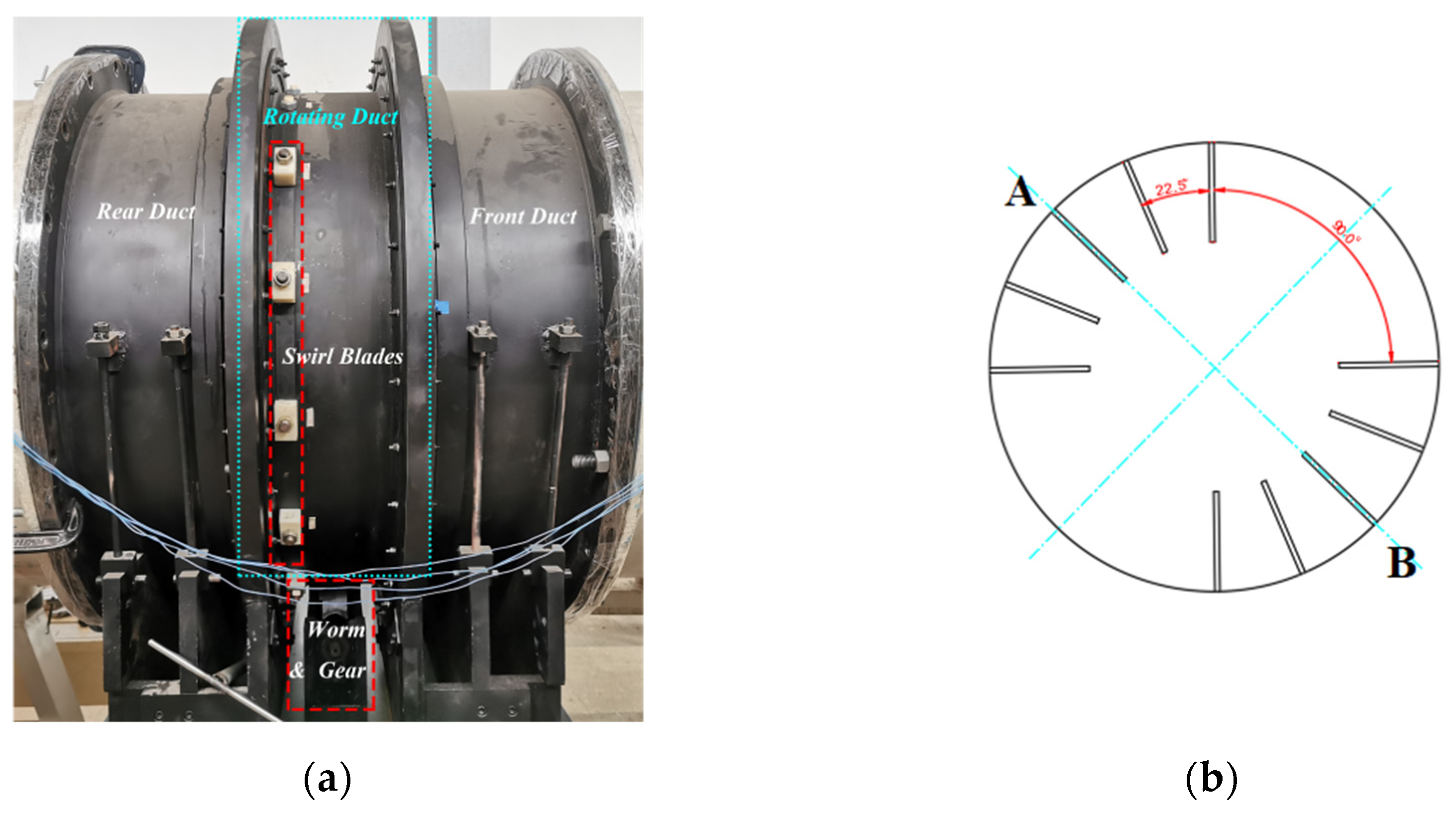
The swirl distortion generator was installed upstream of the compressor, at a distance about 1.5 times the diameter of the intake pipe away from the compressor inlet. It was used to provide the swirl field at the compressor inlet. Figure 3a shows the geometric structure of the swirl distortion generator. In it, the motor drives the worm so that the rotating pipe can steplessly rotate within a range of 55° in the circumferential direction, and the accuracy is 0.1°. The circumferential layout of the swirl blades as shown in Figure 3b was adopted in the experiment. The blades were divided into two groups, A and B, each with five blades. The interval between the blades in each group was 22.5°, and the interval between the two groups was 90°. The stagger angles of the two sets of blades were opposite, which provided the paired swirl distortion at the compressor inlet. The design parameters of the swirl blades are listed in Table 2.

2.3. Experimental Methods

In this paper, experiments were carried out on the compressor with rotor tip clearances of 2 mm and 3 mm. Using the above measuring equipment, the overall characteristics of the compressor under clean and two-intensity paired swirl distortion inlet conditions were measured to reflect the influence of paired swirl distortion. The swirl distortion generator was used to provide swirl distortion inlet condition for the compressor. The stagger angles of the swirl blades were adjusted by the positioning blocks to form swirl distortion with different intensities. The flow coefficient, total pressure ratio, and efficiency were the average results of multiple experiments. The definitions of specific parameter are presented in the next section. In order to investigate the RI of the compressor at different inlet conditions, high-frequency dynamic-wall static-pressure sensors were used to measure the static pressure on the casing at each steady-state operating point and during the process from steady state to complete stall. The model and layout of the sensors were described in the previous section. The definitions of the parameters in post-processing are explained in the next section.

3. Results and Discussion

3.1. Description of the Swirl Flow

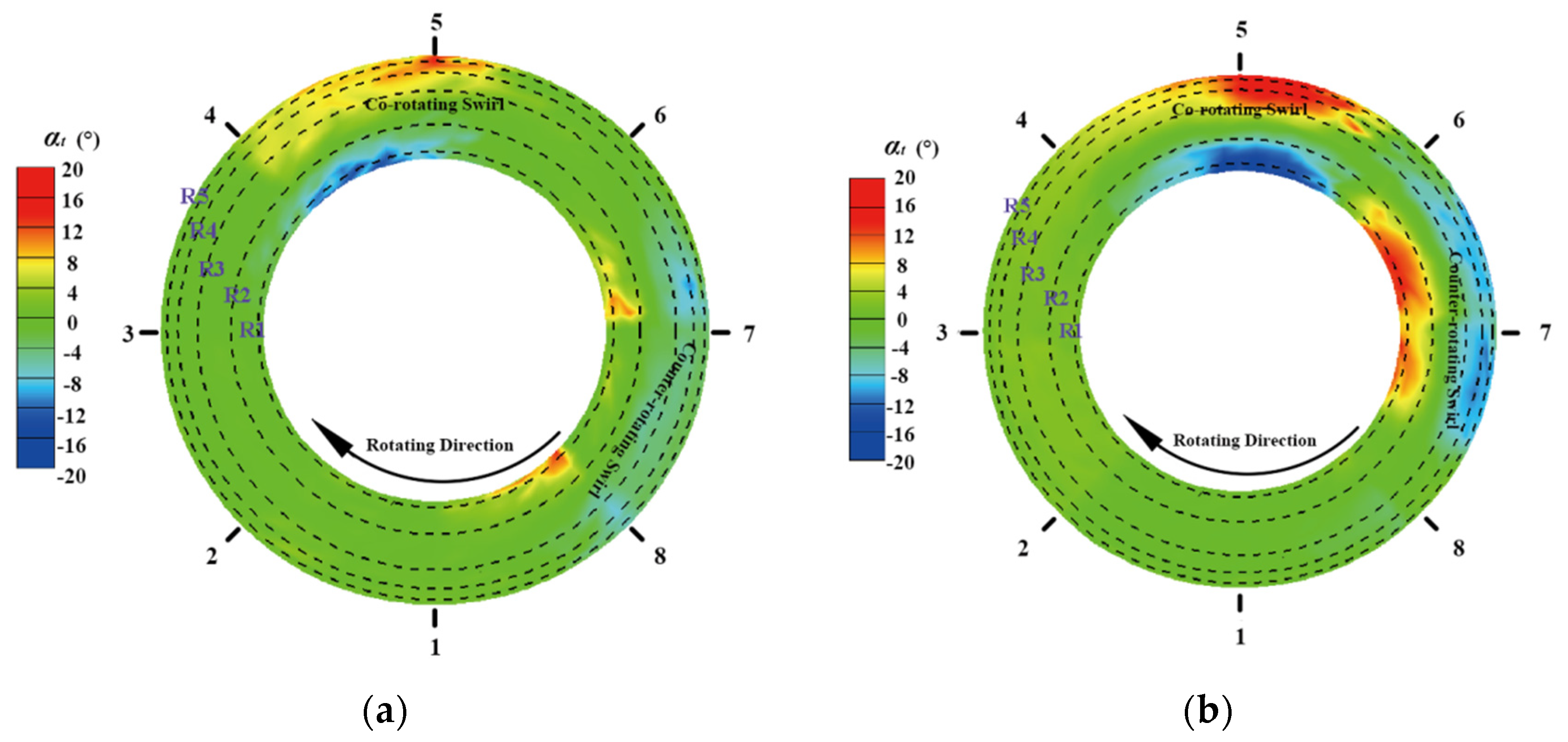
Two intensities of steady paired swirl distortion were considered in the experiment, and the stagger angles of the swirl blades were αst = ±20°and ±40°. The swirl angle (αt) refers to the angle between tangential velocity and axial velocity of the flow, which is defined by Equation (1), where vt and vz represent tangential velocity and axial velocity, respectively. Figure 4 is a cloud diagram of the swirl angle before the rotor inlet, corresponding to two swirl intensities respectively. Two vortices with different rotating directions can be clearly seen; of these, the vortex with the same direction as the rotor is called the co-rotating swirl, while the other is called the counter-rotating swirl [26]. As the flow propagates to the rotor through the swirl distortion generator, the two vortex cores are deflected relative to the center of the blade set (point A and B in Figure 4) due to the influence of vortex convection, natural distortion, and the rotor. The co-rotating swirl deflects towards the direction of the rotor rotation, while the counter-rotating swirl deflects in the opposite direction. As the swirl intensity increases, the deflection becomes more obvious.
αt = arctan(vt/vz)

3.2. Compressor Performance

Figure 5 shows the increase in total and static pressure of compressors with two different rotor tip clearances: 2 mm and 3 mm. The flow coefficient (φ) and the total-to-static pressure rise coefficient (ΨTS) are obtained by Equations (2) and (3), where Um is the rim speed at the rotor pitch diameter, Ps_out is the average static pressure at the compressor outlet, Pt_in is the average total pressure at the inlet.
The influences of two-intensity of steady paired swirl distortions were compared. The two diagrams illustrate that the paired swirl distortions had negative effects on the pressure rise. For the compressor with δ r = 2 mm, the swirl distortion advanced the stall. As the swirl intensity increased, the stall coefficient became larger. However, when δ r increased to 3 mm, the low-intensity swirl distortion increased the stability.
The range of RI is indicated in the figure; it can be observed that RI only occurred in a narrow range. For the compressor with a 2 mm rotor tip clearance, RI was not detected in the experiment with the clean inlet, while the swirl distortions induced RI. For the compressor with δ r = 3 mm, the RI appeared near the stall point under in the presence of the clean inlet. In this case, the inlet paired swirl distortion delayed the appearance of the RI, thereby the stall was put off.
φ = Vz/Um
ΨTS = (Ps_outPt_in)/(0.5ρUm2)

3.3. Effects on Stall Inception

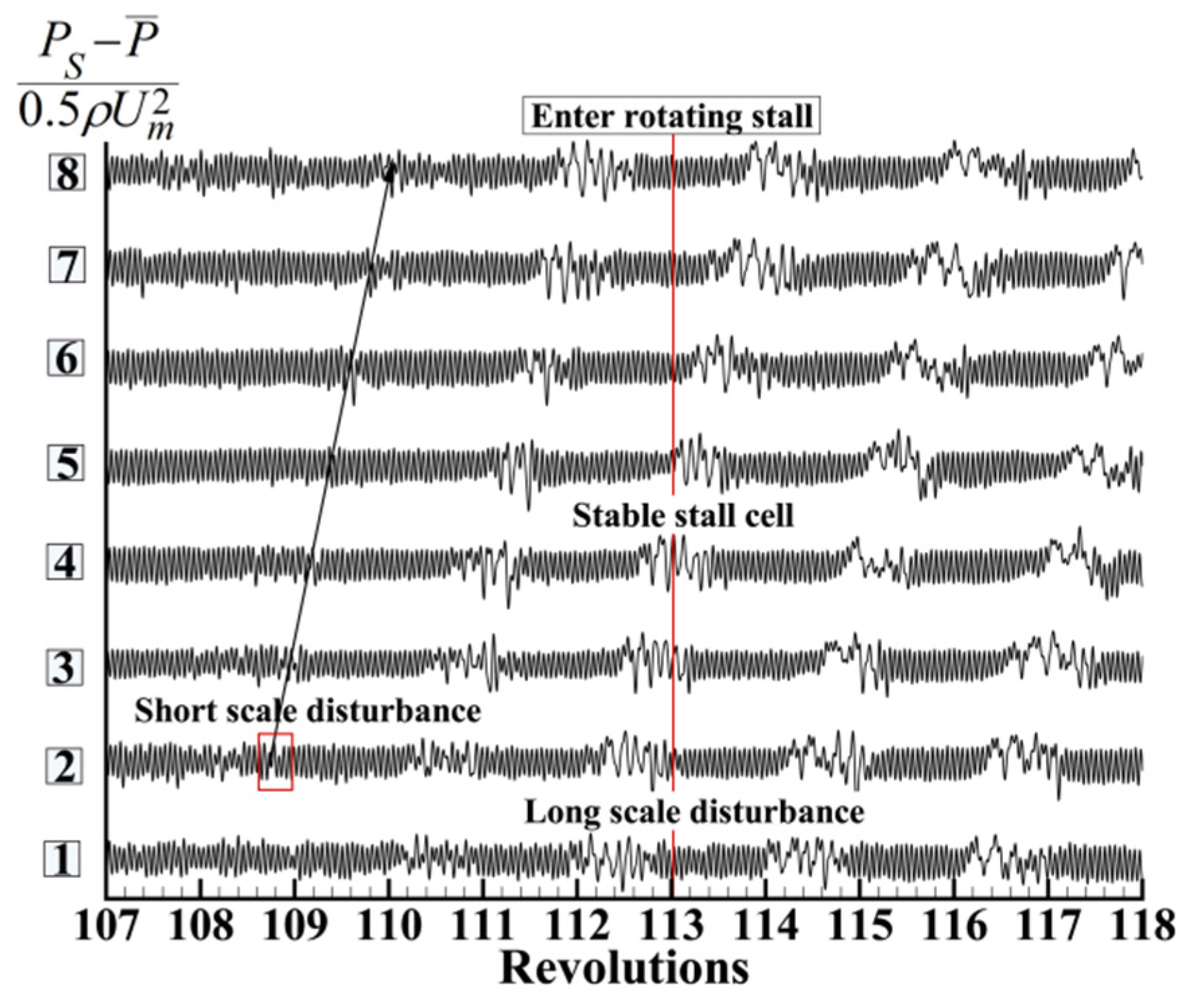
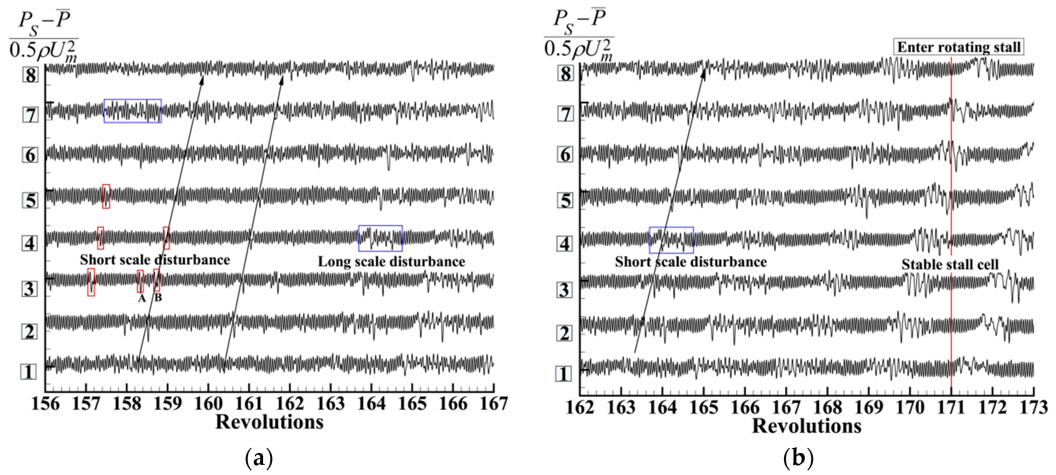
In the experiment, eight dynamic sensors were evenly distributed in the circumferential direction of the casing to capture the rotor wall static pressure. The clean inlet and the two-intensity paired swirl distortion inlet were included. Figure 6 and Figure 7 show the curves of dimensionless dynamic static pressure at various circumferential positions for different inlet conditions. The rotor tip clearance was 2 mm. Figure 8 and Figure 9 show the results for the 3 mm rotor tip clearance. All values were obtained after 90% BPF filtering. For the compressor with a 2 mm rotor tip clearance and the clean inlet, obvious short-scale disturbance appeared. After about four rotor revolutions, the compressor entered the rotating stall.
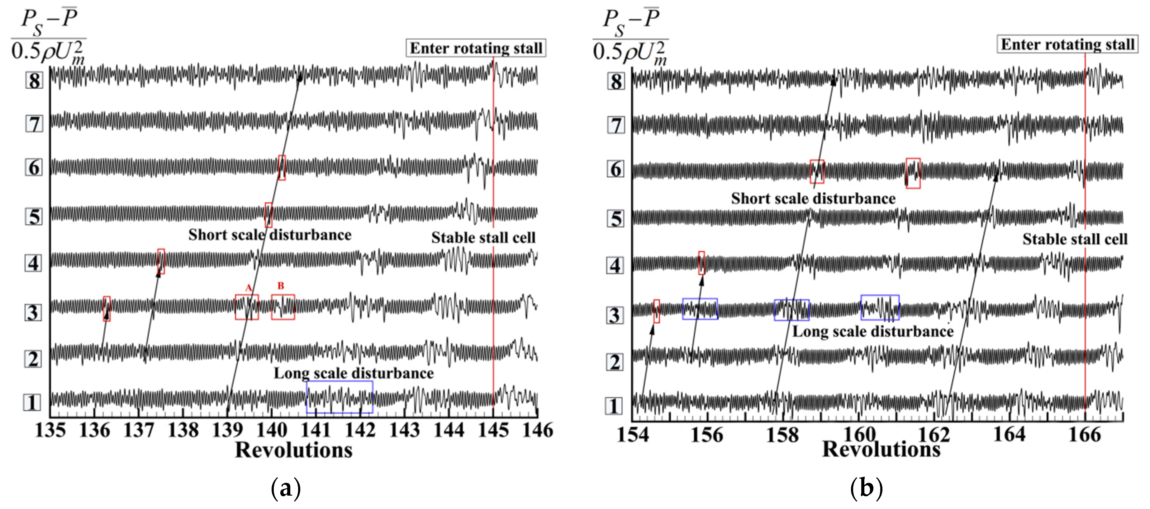
The swirl distortion with αst = ± 20° caused the pressure signals at the monitoring site 7 and 8 to become more chaotic. Therefore, short-scale disturbance was induced at the monitoring site 1 and 2 but failed to spread. At the 139th rotor revolution (in the experiment, the entire process of the compressor from stable working point to deep stall was recorded; the figures report the revolutions counted from the beginning of the collection), two independent disturbances were detected at the monitoring site 3, which then weakened into one single disturbance at station 4. Along with the development of the disturbances, an obvious long-scale disturbance appeared at the 141th rotor revolution and gradually weakened during the propagation to station 6. It then strengthened until developing into the rotating stall. About 9 rotor revolutions elapsed from the generation of an apparent short-scale disturbance to the rotating stall.
When αst = ±40°, the long-scale disturbance formed at station 7 spread to station 3 and induced a small disturbance at station 4, which was then suppressed (Figure 7b). After another revolution, a short-scale disturbance appeared at station 6. During the next few rotor revolutions, the disturbance weakened and strengthened several times and then developed into the rotating stall. It took about 12 rotor revolutions from the onset of the significant short-scale disturbance to reach the compressor stall.
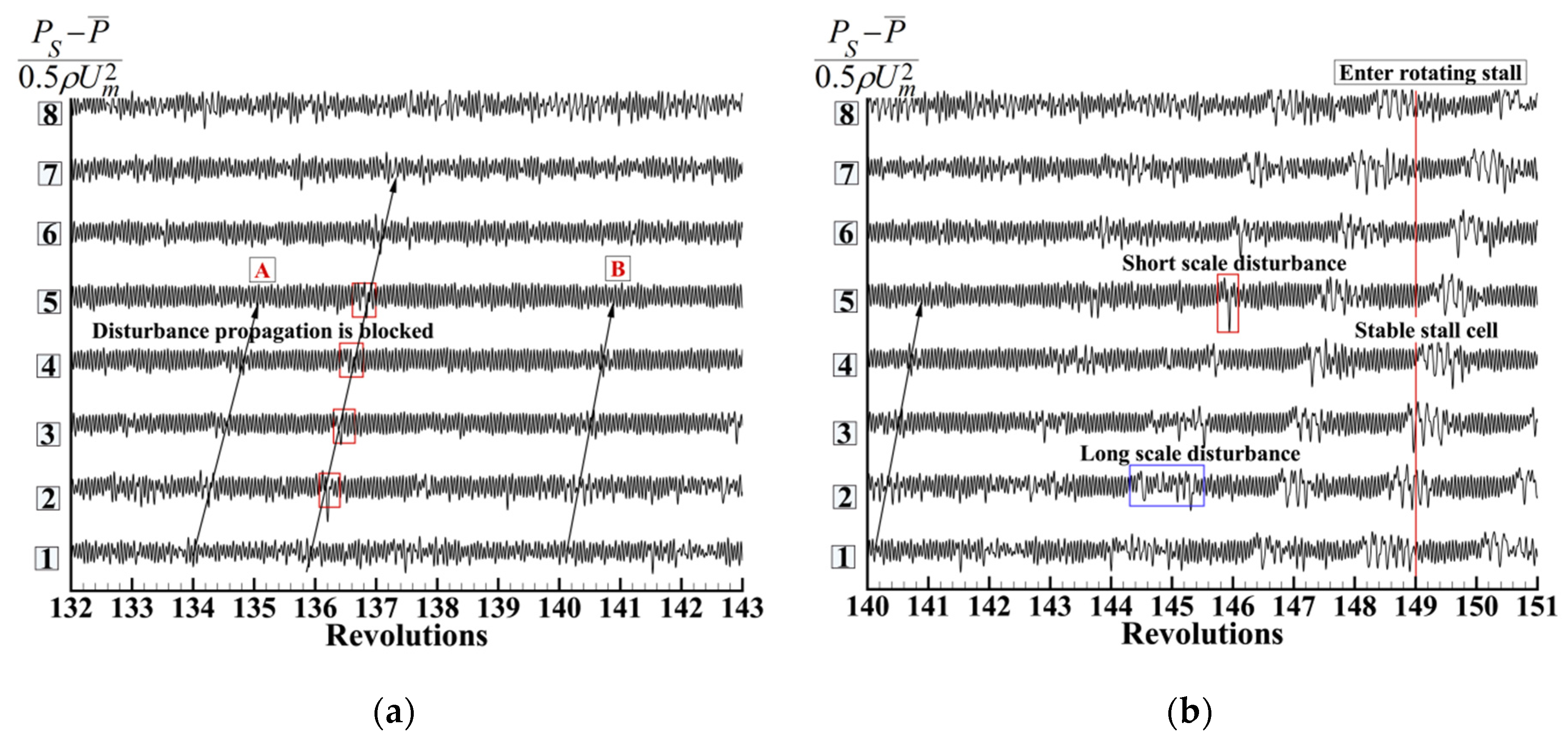
The two pictures (a) and (b) in Figure 8 and Figure 9 better display the development of the disturbance. As the tip clearance increased to 3 mm, the disturbances of the rotor tip near the stall point became chaotic. However, generally speaking, the stall process in this case was as follows: the short-scale disturbance in local position gradually developed into a large-scale disturbance and finally into the rotating stall. From the occurrence of the disturbance to the rotating stall, 14 rotor revolutions occurred. For the compressor subjected to inlet swirl distortion with αst = ±20°, it was found that the disturbance propagation was interrupted (point A and B in Figure 9a) or weakened at stations 4 and 5. Before the compressor entered the stall, the short-scale disturbance and long-scale disturbance developed alternately and finally formed a stable stall cell.
The above research indicated that for the compressor with the clean inlet, the short-scale disturbance always appeared first and gradually developed into a large-scale disturbance, then forming a stable stall cell. The paired swirl distortion provided different attack angles to the rotor tip at different circumferential positions. The co-rotating swirl at station 4 and 5 produced a positive influence, reducing the attack angle, while the counter-rotating swirl at stations 7 and 8 produced an opposite effect (Figure 4). Therefore, when the disturbance generated at station 7 propagated to station 4, it was weakened by the co-rotating swirl there, so that the long-scale disturbance turned into a short-scale disturbance and the short scale disturbance was further weakened or suppressed. Similarly, the short-scale disturbance at station 6 was enhanced into a long-scale disturbance via the counter-rotating swirl sector. Once the co-rotating swirl could no longer provide effective attenuation, the compressor rapidly entered the stall.

3.4. Rotating Instability with Paired Swirl Distortion Inlet

The pressure signals sampled by 8 sensors were processed by FFT transformation. Figure 10 shows the frequency spectrum of the compressor with a 2 mm rotor tip clearance at three different operating points, including clean and two-intensity steady paired swirl distortions. The operating points A and B are as indicated in Figure 5. These pictures indicate that as the flow coefficient decreased to the near stall point, the signals of RI were not captured at the rotor tip of the compressor with the clean inlet; only the BPF and some weak clutter signals were detected. In the case of the paired swirl distortion inlet, some relatively clear signals of RI were detected at the operating point B. The closer to the stall point, the more obvious was the RI in the compressor. The RI signals were preferentially captured by the sensor at station 6 and gradually developed along the direction of the compressor rotor rotation. Near the stall point, the RI could be detected by three consecutive sensors (sensor 6, 7, and 8), and the signals were already very weak in station 1.
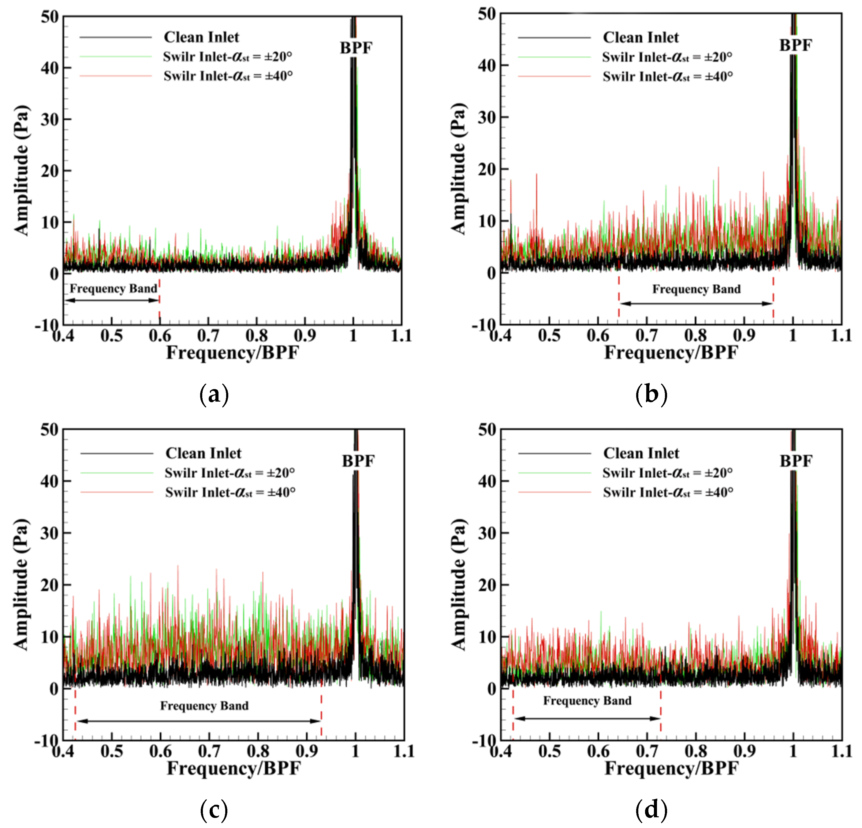
The spectra of RI signals near the stall point are listed in Figure 11; the rotor tip clearance of the corresponding compressor was 2 mm. The rotation frequencies of the RI are shown as a band from 0.5 BPF to 0.9 BPF. The amplitude of the RI at station 7 was the largest, and the bandwidth was also the widest. The RI decreased in amplitude and bandwidth as it propagated towards station 1. That is to say, the RI was only concentrated in the counter-rotating swirl sector. Once it was far away from the counter-swirl sector, the RI was weakened until it disappeared.
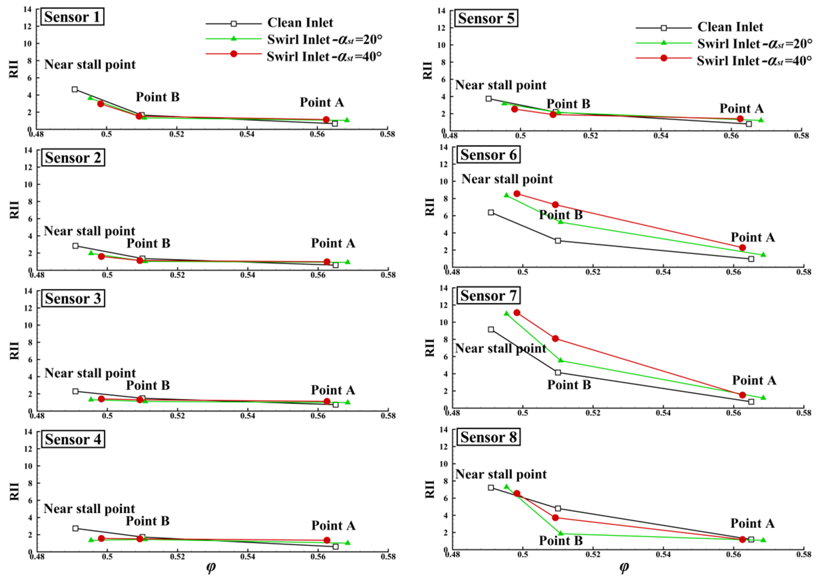
Since the frequency of the RI signal found in the experiment was mainly in the bandwidth of 0.5–0.9 BPF, the RI intensity (RII) was defined as the amplitude integral corresponding to the frequency band of 0.5–0.9 BPF, which was used characterize the RI intensity at the rotor blade tip. It was calculated using the equation:
RII = 0.5 B P F 0.9 B P F Am ( f ) df
In the formula, Am(f) is the amplitude of the signals. Figure 12 presents the influence of the paired swirl distortion with different intensities on RRI at three different working points ( δ r = 2 mm). Compared with the case of the clean inlet, at station 6, the paired swirl distortion with the two intensities increased the RRI at the operating point B by 69.8% and 135.8%, and the RRI near the stall point was increased by 30.8% and 34.2%. The value at station 7 also changes significantly. At the operating point B, the RRI increased by 33.4% and 95.4%, while at the near stall point, the RRI increased by 19.8% and 21.3%. At the remaining circumferential positions, changes in import conditions did not have an impact on RRI.
Tip leakage flow is one of the important causes of RI. Figure 13 and Figure 14 show the dynamic static pressure of the rotor tip measured at station 7. These two figures compare the flow field of the rotor tip region at the operating point A and near the stall point in the case of paired swirl distortion at two intensities. Compared with the operating point A, multiple shedding vortices were observed on the suction surface of the rotor, which fluctuated with the rotation of the compressor. This is reflected in the frequency band on the spectrum diagram, as shown in Figure 11.
For the paired swirl distortion with αst = ±40°, the shedding vortices on the suction surface of the rotor blade were more obvious, and the low-pressure area was larger, gradually extending towards the pressure suction surface of the next blade, as shown in Figure 14. The above two comparison diagrams show that the shedding vortex at the rotor tip area near the stall point was the main reason for the RI of the compressor.
The frequency spectrum of the 3 mm rotor tip clearance compressor with different inlet conditions is shown in Figure 15; the flow coefficient was 0.495. In the compressor with a clean inlet, the RI mainly occurred at stations 6, 7, and 8 and concentrated at stations 7 and 8. Different from the results above, the co-rotating swirl and counter-rotating swirl in this case had obvious opposite effects: the co-rotating swirl at stations 5 and 6 weakened the RI, while the counter-rotating swirl at stations 7 and 8 enhanced the RI. The RII values corresponding to Figure 15 are listed in detail in Table 3, and the increase of RRI caused by paired swirl distortion relative to the clean inlet is shown. From this table, it can be seen more intuitively that the swirl distortion affected the RI at different circumferential positions.
Figure 16 compares the static pressure diagram at the rotor tip with clean inlet and paired swirl distortion inlet. The static pressure was measured at station 6 with the flow coefficient of 0.495. The results indicated that there were shedding vortices on the suction surface of several blades, and the leading-edge overflow was captured on very few blades. Here, the co-rotating swirl in the distortion improved the flow field. As shown in the figure, the co-rotating swirl reduced the generation of the shedding vortices at station 6 and inhibited the formation of the leading-edge overflow, thereby improving the flow field here and weakening the generation of RI.
Through the above analysis, it can be concluded that the stall of the compressor with steady paired swirl distortion was closely related to the RI. The RI only occurred in a very narrow operating range. The counter-rotating swirl in the distortion could induce or enhance the RI, while the co-rotating swirl suppressed the RI and improved the flow field of the rotor blade tip. The existence of shedding vortices on the suction surface of the rotor blades was an important factor that led to RI. The generation or suppression of the shedding vortices directly affected the occurrence and disappearance of RI signals. Because of the oscillation of the shedding vortices, the RI was not a single-peak frequency but a frequency band.

4. Conclusions

In this paper, the effects of two-intensity steady paired swirl distortions on the characteristics of a single-stage compressor with rotor tip clearances of 2 mm and 3 mm, the initial development of stall, and RI were investigated. Based on the dynamic measurement of the wall static pressure at the rotor tip, the flow field at the rotor tip under the conditions of clean inlet and steady paired swirl distortion was compared and analyzed. The characteristics of RI at different circumferential positions under paired swirl distortion were explored for the first time, and the variation of RI was quantitatively analyzed The main results are as follows:
  • Due to the existence of the paired swirl distortion, the initial development of the compressor stall involved the alternation of short-scale disturbance and long-scale disturbance. The long-scale disturbance in the counter-rotating swirl sector propagated along the direction of the rotor rotation and was suppressed in the non-swirl and co-rotating swirl sectors, turning into short-scale disturbance or even disappearing, until the counter-rotating swirl sector was reached in the next revolution, and the disturbance strengthened again. Once the co-rotating swirl no longer restrained the development of the disturbance, the compressor rapidly entered the stall.
  • In the case of the paired swirl distortion inlet, the obvious RI mainly existed in the counter-rotating swirl sector.
  • For the compressor with a 2 mm rotor clearance, both paired swirl distortions with αst = ±20° and αst = ±40° induced RI. Compared with the RRI in the case of a clean inlet, when αst = ±20°, RRI increased by 69.8%, and when αst = ±40°, RRI increased by 135.8%.
  • As the rotor clearance increased to 3 mm, the paired swirl distortion with αst = ±20° had different effects on RI at different circumferential positions. The counter-rotating swirl part strengthened the RI, and the RRI increased significantly, with a maximum value of 7.79, while the co-rotating part suppressed the RI, and the RRI decreased, reaching the value of 4.45.
  • The enhancement and weakening effect of the paired swirl distortion on RI were attributed to the generation and suppression of shedding vortices at the rotor blade tip. In the compressor with a 3 mm rotor clearance, the co-rotating swirl inhibited the formation of shedding vortices and ameliorated the flow field of the rotor tip, thus delaying the stall. However, in the compressor with a 2 mm rotor tip clearance, the counter-rotating swirl deteriorated the flow field at the rotor tip, and the generation of shedding vortices induced RI, which promoted the advancement of the stall.

Author Contributions

The main tasks of the authors in this article are as follows: proposal and verification of experimental research scheme: R.X. and J.H.; experimental funding acquisition: J.H.; design of the compressor: C.J. and R.X.; preparation and completion of the experiment: R.X., X.W., C.J. and J.J.; post-experiment processing and analysis: R.X., X.W., C.J. and J.H.; draft writing and revision: R.X. All authors have read and agreed to the published version of the manuscript.

Funding

The research was funded by National Science and Technology Major Project, grant. No. 2017-Ⅱ-0004-0017.

Conflicts of Interest

The authors declare that there is no conflict of interest among the authors. There is no conflict of interest in the research results mentioned in this article. The funder has no role in the design of the study, in the collection, analyses, or interpretation of data, in the writing of the manuscript, or in the decision to publish the results.

Nomenclature

The nomenclature of the parameters involved in this article is as follows, in order of appearance.
RIRotating instability
BPFBlade passing frequency/Hz
α s t Stagger angle of the swirl blades/°
φ Flow coefficient
Ψ T S Total to static pressure rise coefficient
δ r Rotor tip clearance/mm
P s Static pressure/Pa
P ¯ Mean static pressure/Pa
ρ Density/kg·m−3
U Circumferential speed of rotor/m·s−1

References

  1. Greitzer, E.M. Surge and Rotating Stall in Axial Flow Compressors—Part I: Theoretical Compression System Model. J. Eng. Power 1976, 98, 190. [Google Scholar] [CrossRef]
  2. Storer, J.A.; Cumpsty, N.A. Tip Leakage Flow in Axial Compressors. J. Turbomach. 1991, 113, 252–259. [Google Scholar] [CrossRef]
  3. Suder, K.L.; Celestina, M.L. Experimental and Computational Investigation of the Tip Clearance Flow in a Transonic Axial Compressor Rotor. J. Turbomach. 1996, 118, 218–229. [Google Scholar] [CrossRef] [Green Version]
  4. Lakshminarayana, B. Methods of Predicting the Tip Clearance Effects in Axial Flow Turbomachinery. J. Basic Eng. 1970, 92, 467–480. [Google Scholar] [CrossRef]
  5. You, D.; Wang, M.; Moin, P.; Mittal, R. Large-eddy simulation analysis of mechanisms for viscous losses in a turbomachinery tip-clearance flow. J. Fluid Mech. 2007, 586, 177–204. [Google Scholar] [CrossRef] [Green Version]
  6. You, D.; Wang, M.; Moin, P.; Mittal, R. Prediction and analysis of rotor tip-clearance flows using large-eddy simulation. In Proceedings of the 2004 Users Group Conference (DOD_UGC’04), Williamsburg, VA, USA, 7–11 June 2004; pp. 158–165. [Google Scholar]
  7. Day, I.J. Stall Inception in Axial Flow Compressors. J. Turbomach. 1991, 115I, 1–9. [Google Scholar]
  8. TR Camp. A study of Spike and Modal Phenomena in a Low-Speed Axial Compressor. Trans. ASME J. Turbomach. 1998, 120, 393–401. [Google Scholar]
  9. Nishioka, T.; Kuroda, S.; Kozu, T. Spike and Modal Stall-inception Patterns in a Variable-pitch Axial-flow Fan. Trans. Jpn. Soc. Mech. Eng. 2004, 70, 1746–1753. [Google Scholar] [CrossRef] [Green Version]
  10. Vo, H.D.; Tan, C.S.; Greitzer, E.M. Criteria for Spike Initiated Rotating Stall. J. Turbomach. 2008, 130, 11023. [Google Scholar] [CrossRef]
  11. Mathioudakis, K.; Breugelmans, F. Development of Small Rotating Stall in a Single Stage Axial Compressor. In Proceedings of the ASME 1985 International Gas Turbine Conference and Exhibit, Houston, TX, USA, 18 March 1985. [Google Scholar]
  12. Mailach, R.; Sauer, H.; Vogeler, K. The Periodical Interaction of the Tip Clearance Flow in the Blade Rows of Axial Compressors. ASME Pap. 2001, 78507, 1–9. [Google Scholar]
  13. Mailach, R.; Lehmann, I.; Vogeler, K. Rotating Instabilities in an Axial Compressor Originating from the Fluctuating Blade Tip Vortex. J. Turbomach. 2001, 123I, 453–460. [Google Scholar] [CrossRef]
  14. Biela, C.; Müller, M.W.; Schiffer, H.-P.; Zscherp, C. Unsteady Pressure Measurement in a Single Stage Axial Transonic Compressor Near the Stability Limit. In Proceedings of the ASME Turbo Expo 2008, Berlin, Germany, 9–13 June 2008. [Google Scholar]
  15. Schreiber, J.; Paoletti, B.; Ottavy, X. Observations on rotating instabilities and spike type stall inception in a high-speed multistage compressor. Int. J. Rotating Mach. 2017, 2017, 7035870. [Google Scholar] [CrossRef] [Green Version]
  16. März, J.; Hah, C.; Neise, W. An Experimental and Numerical Investigation into the Mechanisms of Rotating Instability. J. Turbomach. 2002, 124, 367–374. [Google Scholar] [CrossRef]
  17. Hah, C.; Bergner, J.; Schiffer, H. Tip clearance vortex oscillation, vortex shedding and rotating instabilities in an axial transonic compressor rotor. ASME Pap. 2008, 43161, 57–65. [Google Scholar]
  18. Hah, C.; Voges, M.; Mueller, H. Schiffer, Characteristics of tip clearance flow instability in a transonic compressor. ASME Pap. 2010, 44021, 63–74. [Google Scholar]
  19. Wu, Y.; Wu, J.; Zhang, G.; Chu, W. Experimental and Numerical Investigation of Flow Characteristics Near Casing in an Axial Flow Compressor Rotor at Stable and Stall Inception Conditions. J. Fluids Eng. 2014, 136, 111106. [Google Scholar] [CrossRef]
  20. Chen, Z.; Wu, Y.; An, G. Tip leakage flow, tip aerodynamic loading and rotating instability in a subsonic high-speed axial flow compressor rotor. Aerosp. Sci. Technol. 2021, 110, 106486. [Google Scholar] [CrossRef]
  21. Inoue, M.; Kuroumaru, M.; Tanino, T.; Yoshida, S.; Furukawa, M. Comparative Studies on Short and Long Length-Scale Stall Cell Propagating in an Axial Compressor Rotor. J. Turbomach. 2001, 123, 24–30. [Google Scholar] [CrossRef]
  22. Vo, H.D. Role of Tip Clearance Flow in Rotating Instabilities and Nonsynchronous Vibrations. J. Propuls. Power 2010, 26, 556–561. [Google Scholar] [CrossRef]
  23. Holzinger, F.; Wartzek, F.; Jüngst, M.; Schiffer, H.; Leichtfuss, S. Self-Excited Blade Vibration Experimentally Investigated in Transonic Compressors: Rotating Instabilities and Flutter. J. Turbomach. 2016, 138, 041006. [Google Scholar] [CrossRef]
  24. Li, T.; Wu, Y.; Ouyang, H. Numerical investigation of tip clearance effects on rotating instability of a low-speed compressor. Aerosp. Sci. Technol. 2021, 111, 106540. [Google Scholar] [CrossRef]
  25. Yue, S.; Wang, Y.; Zhang, Z.; Wei, L.; Wang, H. Experimental investigation of rotating instability in a contra-rotating axial flow compressor. Aeronaut. J. 2021, 125, 742–762. [Google Scholar] [CrossRef]
  26. Society of Automotive Engineers. A Methodology for Assessing Inlet Swirl Distortion. Aerospace Information Report No. AIR 5686, October 2010; Reaffirmed July 2017. Available online: https://www.sae.org/standards/content/air5686/ (accessed on 10 September 2021).
  27. Frohnapfel, D.J.; O’Brien, W.F.; Lowe, K.T. Fan Rotor Flow Measurements in a Turbofan Engine Operating with Inlet Swirl Distortion. In Proceedings of the 55th AIAA Aerospace Sciences Meeting, Grapevine, TX, USA, 9–13 January 2017. [Google Scholar]
  28. Sheoran, Y.; Bouldin, B.; Krishnan, P.M. Compressor Performance and Operability in Swirl Distortion. J. Turbomach. 2012, 134, 041008. [Google Scholar] [CrossRef]
  29. Naseri, A.; Boroomand, M.; Sammak, S. Numerical Investigation of Effect of Inlet Swirl and Total-pressure Distortion on Performance and Stability of an Axial Transonic Compressor. J. Therm. Sci. 2016, 25, 501–510. [Google Scholar] [CrossRef]
  30. Dong, X.; Sun, D.; Li, F.; Jin, D.; Gui, X.; Sun, X. Effects of Stall Precursor-Suppressed Casing Treatment on a Low-Speed Compressor with Swirl Distortion. J. Fluids Eng. 2018, 140, 091101. [Google Scholar] [CrossRef]
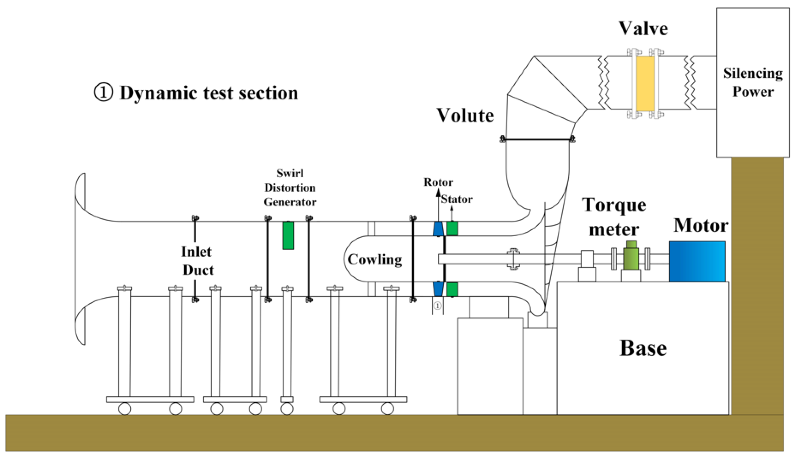
Figure 1. Schematic diagram of the cross-sectional structure of the experimental platform.
Energies 14 08057 g001
Figure 2. Circumferential and axial layout of dynamic pressure measuring points on the casing near the rotor. (a) Circumferential layout of the dynamic sensors; (b) Circumferential layout of the dynamic sensors.
Energies 14 08057 g002
Figure 3. Swirl distortion generator and layout of the swirl blades. (a) Physical photo of the swirl distortion generator; (b) The layout of the swirl blades.
Energies 14 08057 g003
Figure 4. Swirl angle distribution diagram at the inlet section of the rotor. (a) αst = ±20°; (b) αst = ±40°.
Energies 14 08057 g004
Figure 5. Comparison of the increasing total and static pressures of compressors with clean inlet and swirl distortion inlet ( δ r : 2 mm & 3 mm). (a) δr = 2 mm; (b) δr = 3 mm.
Energies 14 08057 g005
Figure 6. The dimensionless dynamic pressure measured on the casing near the rotor leading edge; clean inlet and δr = 2 mm.
Energies 14 08057 g006
Figure 7. The dimensionless dynamic pressure curves at different circumferential positions, measured on the casing near the rotor leading edge, swirl distortion inlet and δr = 2 mm. (a) αst = ±20°; (b) αst = ±40°.
Energies 14 08057 g007
Figure 8. The dimensionless dynamic pressure measured on the casing near the rotor leading edge; clean inlet and δr = 3 mm. (a) Revolutions from 156 to 167; (b) Revolutions from 162 to 173.
Energies 14 08057 g008
Figure 9. The dimensionless dynamic pressure curves at different circumferential positions, measured on the casing near the rotor leading edge, swirl distortion inlet, αst = ±20° and δr = 3 mm. (a) Revolutions from 132 to 143; (b) Revolutions from 140 to 151.
Energies 14 08057 g009
Figure 10. Spectrums of dynamic pressure signals sampled by eight sensors at different circumferential positions in three operating conditions, clean and swirl distortion inlet, δr = 2 mm.
Energies 14 08057 g010
Figure 11. Spectrums of RI signals near the stall point, clean and swirl distortion inlet, δr = 2 mm. (a) Sensor 1; (b) Sensor 6; (c) Sensor 7; (d) Sensor 8.
Energies 14 08057 g011
Figure 12. Effects of paired swirl distortion with two intensities on RRI at different circumferential positions, δr = 2 mm.
Energies 14 08057 g012
Figure 13. The dimensionless static pressure distribution diagram at the rotor tip of the operating point A and near-stall point, measured at station 7, with paired swirl distortion, αst = ±20° and δr =2 mm.
Energies 14 08057 g013
Figure 14. The dimensionless static pressure distribution diagram at the rotor tip of the operating point A and near the stall point, measured at station 7, with paired swirl distortion, αst = ±40° and δr = 2 mm.
Energies 14 08057 g014
Figure 15. Spectrum of dynamic pressure signals sampled by eight sensors at different circumferential positions for near-stall condition, clean and swirl distortion inlet, δr = 3 mm, αst = ±20°, φ = 0.495.
Energies 14 08057 g015
Figure 16. The dimensionless static pressure distribution diagram at the rotor tip at the operating point A and near-stall point, measured at station 6, with paired swirl distortion, αst = ±20° and δr = 3 mm.
Energies 14 08057 g016
Table 1. Parameters of the compressor.
Related ParameterValue
Rotational speed/r·min−11500
Rotor hub/tip ratio0.6
Blade numbers19/22
Aspect ratio at pitch diameter1.459/1.709
Tip clearance (1)/mm2/2
Tip clearance (2)/mm3/2
Table 2. Design parameters of the swirl blades.
Design ParametersValue
Chord length, mm100
Blade height, mm200
Camber angle, °20
ProfileNaca65 series
Table 3. Values of RII at different circumferential positions, δr = 3 MM, φ = 0.495.
Inlet ConditionSensor 1Sensor 2Sensor 3Sensor 4Sensor 5Sensor 6Sensor 7Sensor 8
Clean6.484.133.967.9012.5114.699.4511.68
αst = ±20°10.357.195.847.118.2310.2417.2516.54
Absolute increase3.863.061.88−0.79−4.28−4.457.794.86
Relative increase59.6%74.1%47.5%−10.0%−34.2%−30.3%82.4%41.6%
Publisher’s Note: MDPI stays neutral with regard to jurisdictional claims in published maps and institutional affiliations.