Article

Reburning of Animal Waste Based Biomass with Coals for NOx Reduction, Part II: Dairy Biomass (DB) and Coal–DB Blends

1
Mechanical Engineering, Texas Engineering Experiment Station, Texas A&M University, College Station, TX 77843, USA
2
Currently at Energy Resources Research Department, Research Institute of Industrial Science & Technology (RIST), Pohang 790-600, Korea
3
Texas Agri-Life Research, Texas A&M University System, Amarillo, TX 70106, USA
*
Author to whom correspondence should be addressed.
Energies 2021, 14(23), 8076; https://doi.org/10.3390/en14238076
Submission received: 27 August 2021 / Revised: 24 October 2021 / Accepted: 1 November 2021 / Published: 2 December 2021

Abstract

:
Concentrated animal feeding operations (both slaughter and dairy cattle) lead to land, water, and air pollution if waste storage and handling systems are not effectively managed. At the same time, cattle biomass (CB), which includes both slaughter/feedlot biomass (FB) and dairy biomass (DB), have the potential to be a source of green energy at coal-fired power plants. Part I presented results on NOx reductions with pure FB or Coal: FB blends as reburn fuels. Part II deals with results from reburning with pure DB or Coal: DB blends as reburn fuels. A mixture of NG with a small amount of NH3 was used to generate the baseline NOx of 400–420 ppm (or 185–194 g/GJ). NOx emissions were found to be reduced by as much as 96% when reburning with FB. The effects of reburn fuel type, equivalence ratio (ERRBZ) in the reburn zone, vitiated air, several injection configurations of reburn fuel and initial NO concentrations on NOx emissions were investigated. The ERRBZ shows a significant effect on the NOx reduction. The 20% heat input by reburning was the better operating condition for the long-term operation due to its ash production. The results reveal that reburn with DB fuels is an effective technology for NOx emission control when the initial NOx emission is higher than 275 ppm (or 127 g/GJ or 0.3 lb/MMBtu).

1. Introduction and Literature Review

Electric power utilities consume 80% of the one billion tons of coal produced annually [1]. Recently, renewable alternative fuels have been experimented either as co-fired fuels or as reburn fuels. In co-firing, the renewable fuel is mixed with coal and fired in existing pulverized coal-fired boiler burners. In the reburn process, usually natural gas (NG) as a reburn fuel (RF) is injected downstream of coal-fired boiler burners to reduce NOx generated by coal burners {list of Acronyms at end of Text}. A conventional, upward-fired coal-fired burner with reburn fuel injection along with overfire air (OFA) is presented in Figure 1 [2]. The reburn system with NG as the reburn fuel reduced almost 60% of NOx emission when the reburn zone is operated under richer conditions. Due to the increasing cost of NG ($5.02/GJ or $5.30/MMBtu as of 2021), alternate fuels including coals are being used as reburn fuels. As alternate fuels, biomass fuels have attracted close attention in recent years due to growing energy needs, federal mandates to use renewable fuels and shrinking fossil fuel supplies. A comprehensive review on the reburn experiments and important results are summarized in Table 1.
Concentrated animal feeding operations (both slaughter and dairy cattle) lead to land, water, and air pollution if waste storage and handling systems are not effectively managed. Animal wastes/biomass such as cattle manure, chicken litter and pig manure have been proposed for use as co-fired fuel in coal-fired boiler facilities. The use of animal waste-based biomass (AnB) and agricultural biomass (AgB) for combustion is favorable to utilities and environments because they are CO2 neutral fuels. Most AgB fuels have little or no sulfur, thus SO2 emissions can also be reduced by AgB biomass combustion. Extensive research has been carried out in biomass combustion as a technology to reduce coal consumption, lower emissions, and dispose of biomass [3,4,5,6,7,8,9,10,11,12,13,18,23,24,25]. It was found that co-firing 10% AgB with coal reduced NOx emissions by about 10%, since N is low in AgB, but the CO emissions increased [26]. At the same time, cattle manure (termed as cattle biomass, CB), which includes both slaughter or feedlot biomass (FB) and dairy biomass (DB), has the potential to be a source of renewable fuel for coal-fired power plants. The use of CB has been extensively studied as cofired fuel for several applications at Texas A&M University (TAMU) [11,13,25,26,27,28,29,30]. A blend of chicken litter biomass (LB) and coal was combusted in a laboratory-scale fluidized bed combustor and results were obtained on emissions of CO, SO2, H2S and NO. Increased % of LB in the blend reduced SO2. NO emissions had a peak at about 20% of LB in the blend [31]. Further co-combustion of NG and LB using a lab-scale swirling fluidized bed combustor system, combustion efficiency and emissions from the system were evaluated [32].
The CB fuels as RF were first experimented as reburn fuel by Thien and Annamalai using a bench-scale (30 kW) Boiler Burner Facility [27]. The results also revealed about an 80% reduction in NOx emissions in the optimum condition. The process has resulted in a US Patent [33]. Two types of CB—feedlot biomass (FB) and dairy biomass (DB)—can be used for reburning to reduce gaseous emissions. This technology has the potential to reduce NOx emissions in coal-fired boilers located near cattle feedlots and relieves the cattle industry of waste material. Cattle biomass typically contains higher amounts of ash than coals; thus, the use of CB as a co-fired or reburn fuel will generate more ash in the boiler, resulting in more ash deposition on the surfaces of the heat exchanger (HEX) and the boiler wall, and hence, increase the problems of corrosion, slagging and ash fouling. The ash deposition also reduces the heat transfer rate in utility boilers, and hence, boiler performance, boiler efficiency and life span. The fouling studies under co-firing conditions for blends of coal and CB were conducted using a Department of Energy—National Energy Technology Laboratory (DOE-NETL) 150 kW pilot plant facility [29]. The difficulty of ash removal and the ability to restore proper heat transfer were evaluated.
To enhance NOx reduction, meet the NOx emission requirements for coal-fired utilities and help dairy industries dispose of feedlot animal waste or DB, the current study focuses on developing an energy conversion technology using DB as a reburn fuel. A 30 kW (100,000 BTU/h) Boiler Burner Research Facility was used for the reburn experiments and estimation of the optimum operating conditions for the maximum NOx reduction in coal-fired boilers.
To achieve the overall objective above, the current study involves the following tasks: (i) Determination of the physical and chemical properties of all reburn fuels, (ii) Estimation of the minimum amounts of RF injection rate to achieve % heat input required for the best NOx reduction, and (iii) Investigation of the effects of (a) reburn fuel type, (b) equivalence ratio (ER) in the reburn zone (RBZ, ERRBZ or ϕRBZ), (c) reburn heat input, (d) vitiated reburn gas transporting RF, and (e) initial NOx concentration on NOx reduction.

2. Materials and Methods

2.1. Fuel Preparation and Characteristics

The primary fuel fired in the main burner zone is NG, and the reburn fuels considered for current experiments are: Texas Lignite Coal (TXLC), Low Ash Partially Composted Feedlot Biomass (LAPCFB), Low Ash Separated Solid (Partially Composted), Dairy Biomass (LASSDB) and blends of TXLC:LASSDB. The NG used in the experiments consisted of 94.3% methane, 1.7% carbon dioxide, 2.4% ethane, 0.7% nitrogen, 0.5% propane, and trace amounts of several other gases. Based on the NG composition, its unit Carbon Formula {UCF} is CH3.87N0.0068O0.033 with a heating value of 37,050 kJ/m3. It was important to maintain slightly fuel-lean combustion (ϕ = 0.95) in the primary combustion zone to burn the NG completely. The reburn fuels of TXLC were supplied by Luminant Power Corporation, TX. The reburn fuels LAPCFB and LASSDB were collected from feedlots in Amarillo, Texas. For the FB from cattle feedlots, manure is removed from two types of feed pen surfaces. Manure collected on soil surfaces contains considerable amounts of ash and is termed high ash FB, while one collected on fly ash paved surfaces contains low ash content and is termed as low ash FB. For the DB from dairy farms, manure collected on soil surfaces contains excessive amounts of ash and is termed high ash DB, while one collected on concrete surfaces contains low ash content and is termed as low ash DB. Cattle biomass is also characterized by the composting process, which also helps in providing fuel homogeneity. Samples prior to composting are termed as raw manure, and samples taken after about 45 days of composting involving successive wetting and turning cycles are termed partially composted [34]. Samples taken after about 120 days of composting (involving continuing wetting and turning cycles) are termed finished compost.
Proximate and ultimate analyses were performed on RF. Three samples of each fuel were analyzed, and the average values are listed on an as-received basis, a dry basis, and a dry ash-free (DAF) basis in Table 2. Note that (i) properties of NG are dominated by CH4 since it forms a significant mole fraction in NG, and (ii) the properties of TXLC and LAPCFB are the same as in Part I [18], but the properties of DB are presented in this study. The proximate analysis includes moisture, ash, volatile matter (VM), fixed carbon (FC), and higher heating value (HHV). The ultimate analysis comprises the elemental composition of fuel: carbon, hydrogen, oxygen, nitrogen, sulfur.
The tested reburn fuels are pure TXLC (as a baseline fuel), pure LAPCFB, pure LASSDB, and blends of TXLC:LASSDB. The HHV at different conditions and the ash loading in kg/GJ are also indicated in Table 3. The HHV in kJ/kg of stoichiometric air is approximately same for coal, FB and DB, as shown from 2975 to 3210 kJ/kg, which implies that the oxygen consumption will be the same when the same thermal output is maintained, i.e., the same air flow rate is maintained when switching the fuels and the fuel flow is adjusted until similar O2% in the exhaust is maintained when operated under slightly lean conditions. The ash loadings LAPCFB and LASSDB are about 1.5 times more than TXLC. The ash loadings in fuels are determined on energy released basis.
The mineral analysis of ash for the reburn fuels is particularly important since the mineral composition of the ash affects the deposition rate, fusion and melting points, corrosion rate, and erosion rate of HEXs. The mineral analysis and ash fusion temperature (AFT) are presented in Table 4 and Table 5, respectively. Higher alkaline oxide contents (CaO, MgO, Na2O, and K2O) result in a higher probability of fouling due to faster growing oxide layers on HEX surfaces [30]. LAPCFB and LASSDB have high alkaline contents due to the collection of CB from fly ash paved feedlots or concrete surfaces. The ash fusion temperature depends upon the ratio of basic oxides to acidic oxides (B/A), represented as Equation (1). Table 4 lists B/A ratios (last row). The ratio of basic oxides to acidic oxides is 0.34 for TXLC, 1.47 for LASSDB and 2.46 for LAPCFB; the higher the amounts of basic oxides, the lower the AFT. Therefore, LAPCFB shows the lowest AFT of about 1160 °C (2124 °F) and TXLC shows the highest AFT of about 1155°C (2111°F),1225 °C (2238 °F) in reducing and oxidizing atmosphere respectively (Table 5).
B A = Fe 2 O 3   +   CaO   +   MgO   +   Na 2 O   +   K 2 O   +   P 2 O 5 SiO 2   +   Al 2 O 3   +   TiO 2

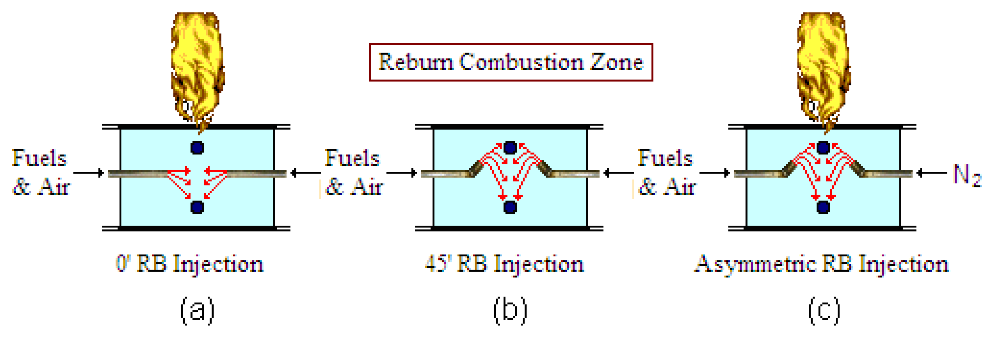
2.2. Experimental Setup

A schematic of the reburn boiler facility is shown in Figure 2. It is a bench-scale 30 kW (100,000 BTU/h) boiler burner, which can be fired with NG as the main fuel and fired with pure coal, the pure DB or coal-DB blends as the RF. The boiler burner consists of a 6 in (15.24 cm) diameter, 72 in (182.88 cm)-long, vertically down-fired combustor. The combustor is made with a steel frame containing a 2 in layer of insulation and a 2 in thick refractory. It is also fitted with two reburn ports, either of a circular cross-section or oval cross-section. In the conventional reburn mode, the primary fuel (NG) and air are injected from the top into the primary combustion zone to produce 70% of the total heat (21 kW or 70,000 BTU/h). The NOx produced in the coal-fired burner is simulated by burning trace amounts of NH3. The NH3 is injected with NG from the top burner and is converted to NOx during combustion. Appendix A.1 presents the formula for estimating the necessary flow rates of NG (about 34 LPM) and NH3 (about 0.12 LPM) to achieve 21 kW along with the desired NO. It is important to maintain a fuel-lean combustion for the conversion of all NH3 to NOx.
The reburn fuel (RF, which could be pure DB or pure coal or coal: DB blends) and air or vitiated air are injected laterally into the RBZ to produce 30% of the total heat (9 kW or 30,000 BTU/h). Appendix A.2 presents the formula for estimating the necessary flow rates of RF to achieve 9 kW (about 42 g of LASSDB/min). Lateral (0°) and 45° upward reburn injectors are used to create various fuel injections in the symmetric and asymmetric (air and N2 as transport gas) configurations. A circular cross-section of the injection nozzles in the symmetric configuration was used for all cases as a base case, except the oval injection. Reburn fuel and air are horizontally injected into the reactor by the 0° injection nozzles (Figure 3a), while they are injected 45° upward by the 45° injection nozzles (Figure 3b). These nozzles produced a velocity of 14 to 18 m/s, depending on flow rates. Along the walls of the boiler burner are temperature measurement ports at spaced intervals 6 in (15.24 cm) below the RBZ. The sampling gas was taken from the center of the reactor. The gas stream is cooled down by the jet water in the quenching area. The exhaust gases vent out of the laboratory through an exhaust system.

2.3. Operational Conditions

The experiment begins with preheating the primary air to 120 °C, and then injecting it into the reactor with the primary fuel (NG). The pre-heat temperature is varied to better control the maximum furnace temperature. A feeder and venturi system entrains the solid reburn fuel in the air, and the reburn fuel and air are injected into the RBZ. After the reburn temperature reaches a steady state condition in the RBZ, an emission gas analyzer was used to determine concentrations of NOx, O2, CO, CO2, SO2 and hydrocarbon (CxHy). The furnace is operated at a slightly negative pressure. The negative pressure ensures that no exhaust gases are emitted into the laboratory. It also ensures that all flames are maintained within the furnace. The vacuum is maintained with an exhaust fan and a damper on the exhaust line.
The following generic equation is used for both main and reburn fuels to determine the required amount of NH3 and air to generate NOx in the main burner zone and to determine the maximum possible CO in the RBZ once all the reburn fuel is consumed under rich conditions. Equation (1) in Part I outlined the overall reaction for C-H-O as the main fuel when burning under fuel-lean conditions [18]. For any C-H-N-O-S fuel burning under rich/lean conditions, the general reaction is written as:
C H h N n O o S s + ( ν s t ) φ ( O 2 + B · N 2 ) + b N H 3 c C O 2 + ( 1 c ) C O + ( h 4 + 3 b 2 ) H 2 O + b N O + s S O 2 + ν s t ( 1 φ 1 ) O 2 + ( ν s t B φ + n 2 ) N 2
where B = 3.76 dry air and ν s t   =   ( 1 + h 4 + s o 2 + 5 b 4 ) . For the natural gas as main fuel (MF) mixed with NH3, b 0, s = 0, ϕ 1, c = 1 under complete combustion. The value of “b” is adjusted to obtain desired “NO” in ppm. The fuel flow required for the primary and reburn combustion was calculated using HHV. The required mass flow rates of the reburn fuel changed for each experiment due to the variation in HHVin order to maintain same heat input % when the reburn fuel is switched. Further, the air flow rate was calculated to obtain the desired equivalence ratio (ER) in the RBZ. The ER in the RBZ was varied from 0.95 to 1.15. The typical heat is generated 70–80% by NG and 20–30% by the reburn fuel. More details are provided in Part I [18]. The vitiated reburn air was simulated by diluting the oxygen concentration with nitrogen to simulate the flue gas recirculation (FGR). Vitiation will increase the injection velocity because there is more mass and volume flow through the reburn injectors. The NOx emissions (125, 275, 420, 630 ppm) produced by the oxidation of NH3 injected were examined. The base case is considered the case of TXLC, with about 400 ppm of the initial NOx emission in the conditions of the non-vitiation, 30% reburn heat input and lateral (0°) reburn injection.
To ensure that all injected NH3 in the main burner was converted to NOx, the levels of NOx were measured before and after the NH3 injection in the primary fuel (NG) combustion. The production of thermal NOx without the NH3 injection was measured between 50 and 70 ppm. After NH3 was injected, the level of NOx was measured between 400 and 420 ppm. This suggested that NH3 was responsible for generating about 350 ppm of NOx{Equation (2)}. The average amount of NH3 injected into the system was 1.44 cm3/s (0.18 SCFH), while the theoretical amount of NH3 required to generate 350 ppm of NOx is 1.82 cm3/s (0.23 SCFH). This suggests that all NH3 injected in the primary zone was converted into NOx. The difference in the theoretical amount required and the amount injected may be attributed to measurement error or other errors inherent in the system.
For the determination of overall system uncertainty, error ranges of instruments and measurements were considered. During the tests, the error ranges of flow meters were observed and calculated for the primary air, reburn motive air, reburn aspirated air, NH3, and NG. The error ranges of all flow meters were determined to be less than ±1.0%. The dominant parameter for overall system uncertainty was the unstable reading of gas concentrations caused by the unstable feed rate of the solid fuels. The fluctuation of data measurements was between ±2.5 and ±5%. Therefore, the final overall system uncertainty was determined in the range of ±3.0 to ±5.3%.

2.4. Size Distribution of Fuel Particles

The Rosin–Rammler distribution is widely used to describe the particle size of pulverized solid fuels [36]. The tested fuels were as fine as we could achieve with present Vortec grinders used for grinding RF. Figure 4 shows the Rosin–Rammler distribution for pure TXLC, pure LAPCFB and pure LASSDB. Particles smaller than 75 μm (200-mesh screen) are 49% for the pure LAPCFB, 23% for the pure TXLC and the pure LASSDB by mass. More than 75% of particles for all fuels are smaller than 300 μm. Theoretically, the finer particle sizes would heat faster and release volatiles more rapidly. Mean size by mass and Sauter mean diameter (commonly abbreviated as SMD or d32) of fuel particles are presented in Table 6. Mass mean size of reburn fuels is 167 μm for TXLC, 150 μm for less fibrous LAPCFB (meat manure) and 242 μm for more fibrous LASSDB (milk producing dairy manure). Since the pure LASSDB contains about 22 w% of 570 μm, its mean size is the largest. The SMD is defined as the diameter of a sphere that has the same ratio of volume to surface area of a given size distribution of particles and used exclusively to determine the average diameter of solid fuel particles. It is represented as Equation (3). The SMD of reburn fuels is 95 μm for TXLC, 50 μm for LAPCFB and 89 μm for LASSDB. LAPCFB contains about 49 w% particles less than 60 μm, and hence, it makes the SMD small.
S M D o r d 32 = i = 1 n d i 3 · n i i = 1 n d i 2 · n i

2.5. Fuel-Nitrogen (N) Analysis

Nitrogen species (HCN, NH3 and N2) derived from fuel-N during combustion are the main sources for NOx formation and reduction in homogeneous gas phase reaction. As the solid fuel pyrolyzes, it releases nitrogen compounds: NH3, HCN and N2.
a {Fuel N atoms} → b HCN + c NH3 + d N2
Typically proportions of NH3:HCN:N2 for coals are 0.3:0.6:0.1, i.e., N in NH3/N in fuel-N = b/a = 0.3 and vice versa. For pig manure, the N distribution is given as NH3:HCN:N2 = 67:6:27 reported in [38], indicating the dominance of NH3 and HCN is zero. Note that for composted manure, some NH3 is lost during composting (28% of NH3 is lost at 700 C and 1.5% is released as N2). The reduction equation of NO with NH3 is given by Equation (4). The differences in N species distribution, as NH3 and HCN, will later be used in interpreting the results on the effect of blended DB and coals on NOx reduction.
N H 3 + 1.5 N O 1.25 N 2 + 1.5 H 2 O

2.6. NOx Emission Relations

The NOx reduction based on mole fractions or [ppm] units alone may not be suitable for the reburn application since a dilution effect by the reburn fuel and air can cause the lower reading of NOx emission in ppm. Thus, dilution effect should be neutralized for the further discussion. The initial gas emissions by NG combustion before the injection of the reburn air were 405 ppm of NOx, 1.1% of O2 and 12.06% of CO2. The gas emissions measured by the ERRBZ from 0.95 to 1.1 were 252 to 262 ppm of NOx, 7.9 to 9.2% of O2 and 7.06 to 7.95% of CO2. The dilution of the reburn air resulted in a one-third decrease in NOx emissions; however, there was no significant dilution effect in NOx emission once the NOx emission was measured on a heat basis [g/GJ]. The NOx emission of 169 g/GJ (or 405 ppm) by NG combustion before the dilution was measured in the range of 166 and 179 g/GJ (or 252 to 262 ppm) after the dilution. The 3% O2 correction by EPA also neutralized the dilution effect, and hence, it can be only applied to the fuel-lean condition. Thus, the emissions of NOx and SO2 on a thermal heat rate basis are described.
(a)
Heating value method
N O x   in   ( k g / G J ) = 3.83 × N O   i n     p p m × C   f r a c t i o n   o f   F u e l x C O 2 × H H V   ( M J / k g )
where C-fraction is the mass fraction of carbon in ‘as received’ fuel, HHV is the higher heating value of the ‘as received’ fuel, and x is the mole fraction [36]. For NOx emission in lb./MMBtu units, see Part I.
(b)
Respiratory Quotient (RQ) Method
The respiratory quotient is defined as follows RQ = CO2 moles produced /O2 moles consumed. The RQ is known from chemical formulae of fuel or from ultimate analyses. Since CO2 in tons/GJ = 0.1 * RQ [37] and the RQ of biomass fuels is higher than the RQ of coal, the biomass emits more CO2 compared to coal!
The RQ method for estimation of NO is useful in case heating values of fuels are not available.
N O x { g G J }     0.103   R Q   N O       i n     p p m       x C O 2
Typically, the XCO XCO2, and hence, the error is negligible. Thus, the amount of CO is neglected in Equations (5) and (6); in case CO is significant, the sum of XCO2 and Xco is used instead of XCO2. RQ values of reburn fuels (RF) are listed in Table 3. For example, at NO = 100 ppm in the exhaust of the facility, NO by the HHV method yields 41 g/GJ, while the RQ method yields 37 g/GJ. Note that when there is presence of CO (rich RBZ), the CO mole fraction is added to the CO2 mole fraction since in real boilers, overfire is used to oxidize CO. When overfire air is added, there is excess oxygen in the overfire air, both NO and XCO2 (due to the presence of O2 in exhaust) are reduced, and hence, NO in kg/GJ may be unaffected.

3. Results and Discussion

3.1. Temperature Distribution within the Reactor

The flue gas temperatures of the vertically down-fired combustor were measured during the experiments. Since the temperature is a significant factor to the reaction rate of NOx formation and reduction, the temperature in the RBZ was monitored and kept below 1600 K to prevent the high production of thermal NOx. In Figure 5a shows the axial gas temperature profiles. The axial temperature linearly decreased along the reactor. Temperatures in downstream gradually increased with time at any given axial distance, while the temperature of the RBZ remained relatively steady. The flue gas was analyzed at the location of 1.37 m below the RBZ, and its radial temperature profile is presented in Figure 5b. The radial gas temperatures were steady almost across the cross-section, indicating a thin boundary layer.

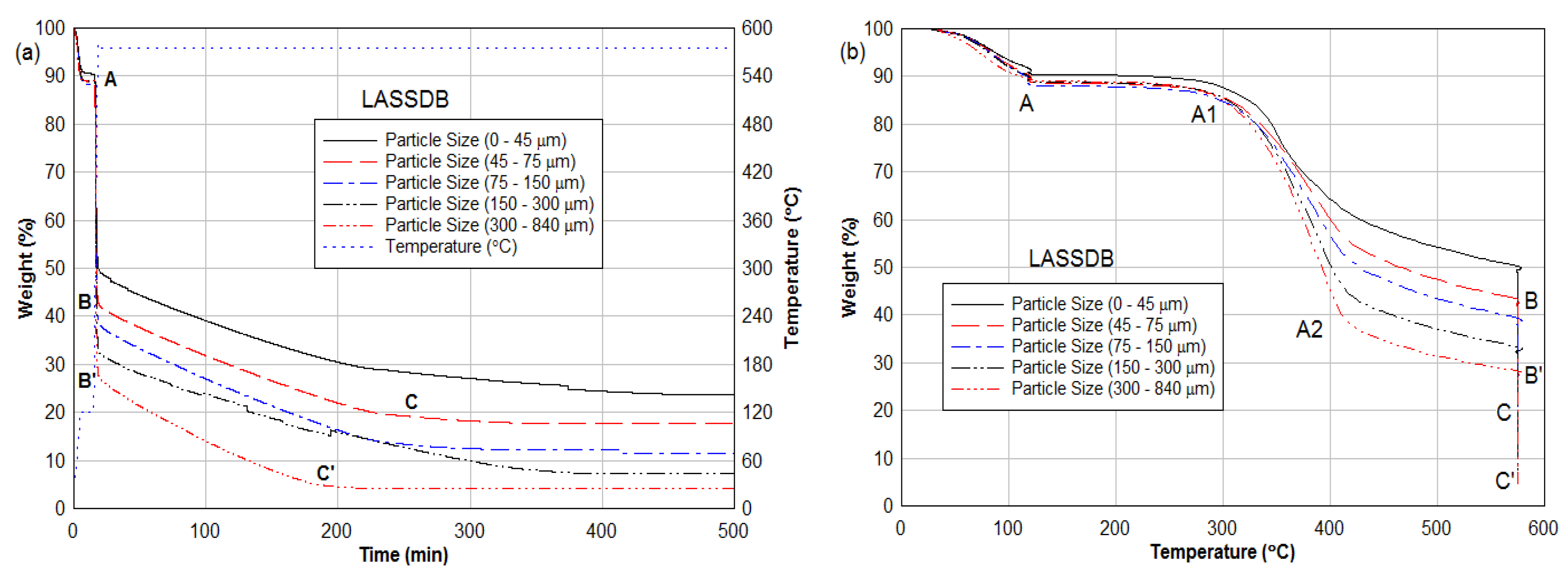
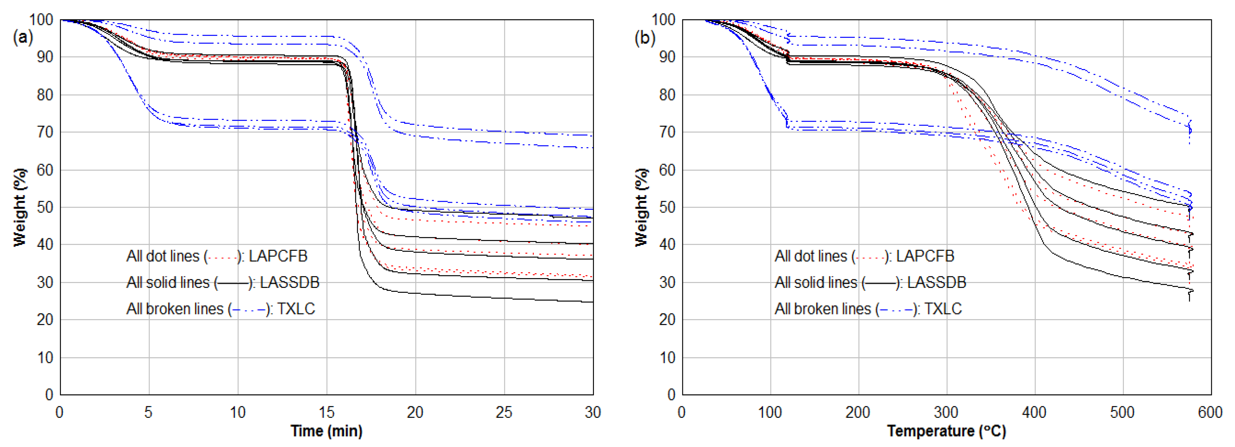
3.2. Thermogravimetric Analysis (TGA)

Pyrolysis was performed using TGA for all pure fuels and their particle sizes. Five ranges of particles size were selected as 0–45, 45–75, 75–150, 150–300, and 300–840 μm. The fuel sample first dried at 120 °C and then heated at 575 °C until the weight change was less than 0.3 mg/h. The release rate of volatiles is typically higher with higher heating rates. The heating rate was 120 °C/min for pyrolysis, which was much lower than the heating rate in the condition where the fuel was injected into the reburn combustion zone (about 1100 °C/s). The pyrolysis results for LASSDB are presented in Figure 6 as a function of time (Figure 6a) and temperature (Figure 6b). In Figure 6a, moisture evaporated is as much as 10% of the total weight for all particle sizes, and the amounts of volatiles released (region A–B or A–B’) is 40 to 60% of the total weight. About 5 to 7% more volatiles were released with an increase in fuel particle size. The majority amounts of volatiles were released within two minutes (region A–B or A–B’) after it started. The remaining volatiles and fixed carbon were released slowly in the region B–C or B’–C’. After 300 min, the primary composition of the fuel sample was ash. It is interesting that the larger particles release more volatiles than the smaller particles. This may be attributed to auto-gasification of large particles, which occurs due to gasification of some fixed C with intrinsic H2O released from the interior of large particles that have thermal gradients.
In Figure 6b, after all moisture was evaporated, minor changes (region A–A1) were found until 300 °C. The majority amounts of volatiles (region A1–A2) were released between 300 and 400 °C. The pyrolysis results of LAPCFB were remarkably like the results of LASSDB (Figure 7). The results of TXLC, however, showed higher moisture evaporations, lower volatile release, and higher fixed carbon compared to biomass fuels.
Figure 7 presents pyrolysis results for all pure fuels including TXLC during the first 30 min. In Figure 7a, the moisture content of TXLC was not uniform with its particle size. The larger the particles, more the moisture content in the particles. The amounts of TXLC volatile were less than half of biomass volatile content. Figure 7b showed that pyrolysis of TXLC slowly started from 400 °C, compared to biomass fuels.

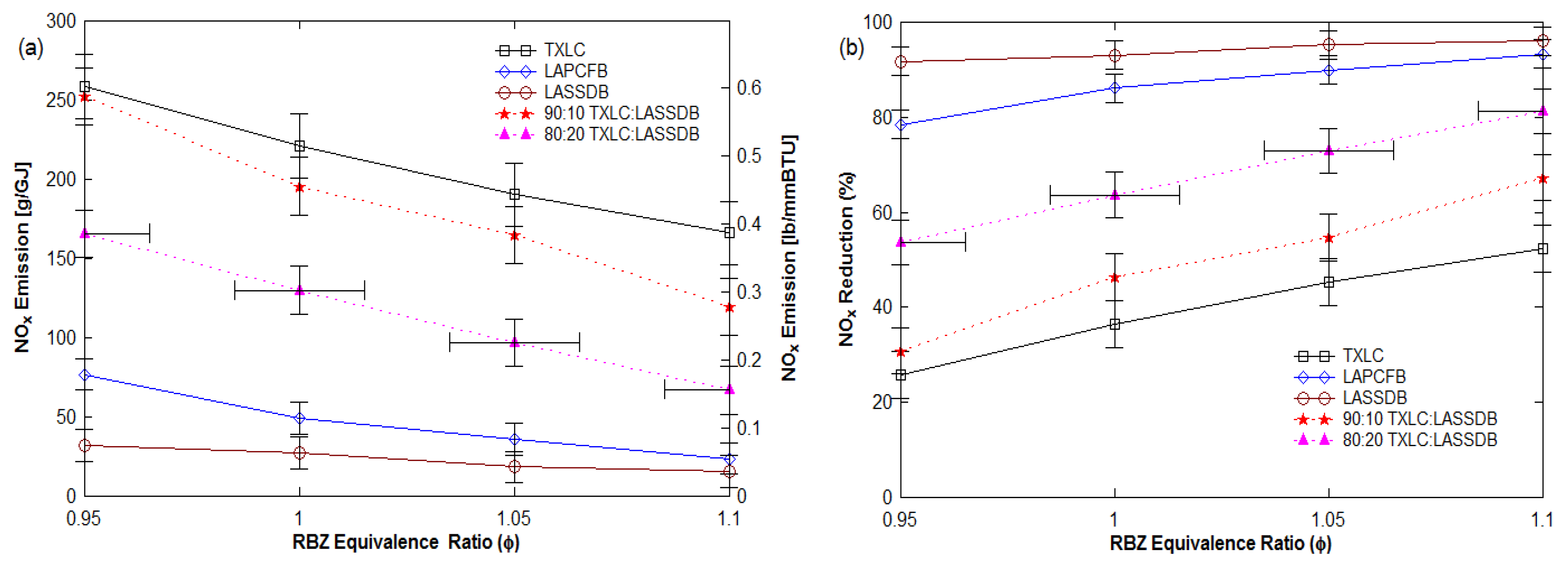
3.3. NOx Emission and % Reduction

This section reports the results on NOx emission, % reduction due to reburn fuel, and effects of ERRBZ, various reburn fuels, vitiation, reburn heat input %, and initial NO concentration on the results for NOx. Since the 45° injection in the asymmetric case (Figure 3c) resulted in poor results (16 to 45%) for NOx reduction and the symmetric injection achieved better results, only symmetric injection results are reported.

3.3.1. Effects of Reburn Equivalence Ratio (ERRBZ or ϕRBZ)

The equivalence ratio (ER) is typically defined as the ratio of the fuel-to-air ratio to the stoichiometric fuel-to-air ratio, which is an inverse value of the stoichiometric ratio (SR). For the emission control of NOx, several reburn fuels were evaluated at various ERs in the RBZ in the conditions of the non-vitiation, 30% reburn heat input and lateral (0°) reburn injection. Figure 8 presents NOx emissions [g/GJ and [lb/MMBtu] (Figure 8a) and reduction % (Figure 8b) as a function of the ERRBZ, and the error bars of each measurement are also shown. The error ranges were determined to be about ± 10 to ±20 g/GJ for NOx emissions, about ±0.015 to ±0.02 for the ERRBZ, and about ±3 to ±5% for NOx reductions, depending on the operating conditions. The initial NOx concentration varied from 400 to 420 ppm. Figure 8a shows the NOx emission decreases with an increase in ERRBZ, since oxygen concentration is reduced in RBZ. Figure 8b shows the increase in in NOx reduction % with an increase in ERRBZ.

3.3.2. Effects of Reburn Fuel

Blends reburn fuels and TXLC showed a great decrease in NOx emission such as 166 to 67 g/GJ for 80:20 TXLC:LASSDB, 252 to 119 g/GJ for 90:10 TXLC:LASSDB and 259 to 166 g/GJ for TXLC. With increased ERRBZ, the oxygen in the RBZ is depleted quickly, and then the low O2 concentration slows down the NOx formation and allows the NOx reduction to be dominant. The extent of NOx reduction was found to be dependent to the ERRBZ, with greater reduction in fuel-rich combustion.
The range of the NOx reductions was found to be 92 to 96% for LASSDB, 78 to 93% for LAPCFB, 54 to 81% for 80:20 TXLC:LASSDB, 31 to 67% for 90:10 TXLC:LASSDB and 26 to 52% for TXLC, depending on the ERRBZ. The results show that both LASSDB and LAPCFB are highly effective in the NOx reduction. Blending of 10% DB with coal increased the NOx reduction up to 15% more, and even up to a 30% increase for the 20% blending. Results indicated NOx reduction increased with an increase in LASSDB proportion in reburn fuels since NH3 content is increased. Consistent findings were reported in our previous experimental results using LAPCFB and TXLC [39]. Therefore, LASSDB and LAPCFB can be used as highly effective reburn fuel for the NOx emission control in coal-fired power plants. Typically, finer particles heat up faster and release volatiles faster, resulting in depleted local O2 level in the RBZ; thus, the NOx reduction is better.
In the current study, the composition of the reburn fuel showed better effects than the size distribution of fuel particles. The SMD (88.84 μm) of LASSDB was larger than the SMD (49.95 μm) of LAPCFB shown in Table 6, while LASSDB contained more fuel-N and less fuel-oxygen, which are responsible for the NOx reduction. From the fuel N, NH3 is produced and reacted with NOx to reduce the NOx. With the 30% reburn heat input, the injected amount of the fuel-N was 0.79 g/min in LASSDB and 0.78 g/min in LAPCFB on a dry ash-free (DAF) basis. Lower amounts of the fuel-oxygen were injected by LASSDB (7.86 g/min) than LAPCFB (9.52 g/min) on a DAF basis. Therefore, LASSDB resulted in higher NOx reduction than LAPCFB due to the higher fuel-N and lower fuel-oxygen. Figure 9 supports the above result by showing the NOx emission with blends of LASSDB and LAPCFB. The NOx emissions increase with a decrease in mass fraction of LASSDB. In Figure 10b, low NOx reductions were achieved by TXLC due to the lower amounts of fuel-N in the form of NH3.

3.3.3. Effects of Vitiated Reburn Air

The use of the flue gas recirculation (FGR) produces less NOx emissions than using air alone, since the low O2 concentration causes the NOx formation rate to be slower and creates rich regions near the fuel injection Though the vitiation causes higher gas velocity and shorter residence time than the non-vitiation, it allows the nitrogen species to be released in an oxygen-deprived region, thus allowing more HCN and NH3 to be available for NOx reduction rather than NOx generation. To simulate the flue gas recirculation, the N2 gas was mixed with the reburn air. This vitiated reburn air caused the oxygen concentration in the RBZ to drop from 20.9 to 12.5%.
The effect of the vitiation on NOx reduction was investigated for 30% reburn heat input and 0° reburn injection. The results shown in Figure 10a indicated that the vitiation decreased NOx emissions, and the larger decrement took place with fuel-rich combustion. In Figure 10b, the vitiation resulted in up to 5% more NOx reduction at ϕRBZ = 1.0 and resulted in up to 14% more NOx reduction at ϕRBZ = 1.1. The use of the real FGR (instead of simulated vitiated gas with N2) gas can increase the level of NOx in the combustion zone due to the FGR gas containing a small amount of NOx.

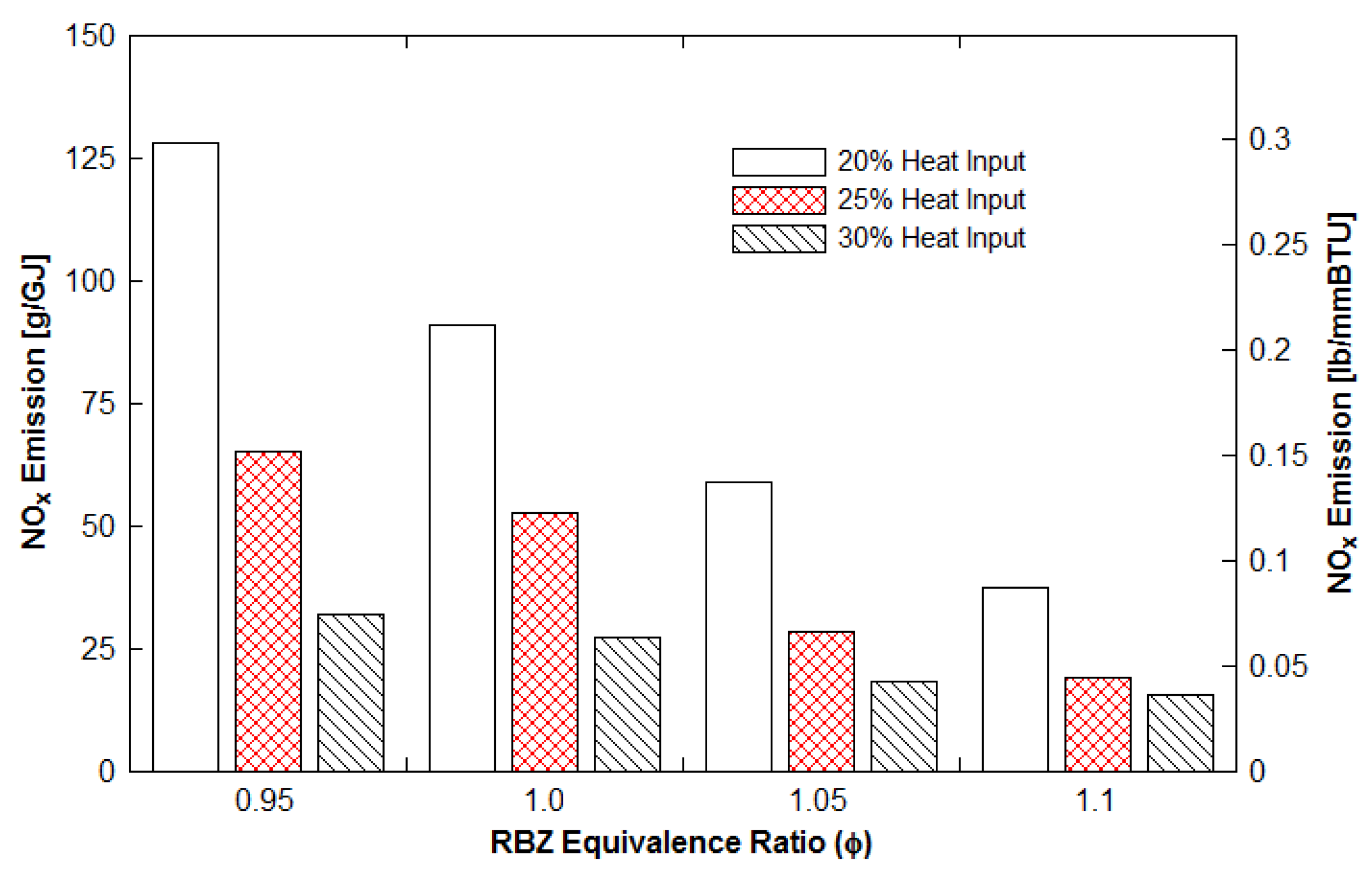
3.3.4. Effects of Reburn Heat Input

Typical heat input generated by a reburn fuel is 10 to 30% of the total heat input; achieving high NOx reductions with less reburn heat input is essentially required with DB. This can reduce the high ash production and the source limitation problem, especially using CB.
Figure 11 presents the effect of the reburn heat input on NOx emission using LASSDB under non-vitiation and lateral (0°) reburn injection. The reburn heat input varied from 20 to 30% with the similar amount of the initial NOx produced by the primary fuel combustion. Once the reburn heat input decreased from 30 to 20%, NOx emissions increased about 2.5 to 4 times depending on the ERRBZ. When reburn heat input % is reduced at the same NO (say 400 ppm), NH3 release from DB is reduced, thus reducing the extent of NO reduction. In fuel-lean combustion (ϕRBZ = 0.95), the increment of the NOx emission was large (32 to 128 g/GJ), while it became smaller (15 to 37 g/GJ) in fuel-rich combustion (ϕRBZ = 1.1). Though higher NOx emissions for the 20% heat input compared to the 30% heat input were found, the high NOx reductions were still achieved between 65 and 90% for the 20% heat input. Considering the results with problems of ash caused by DB, the 20% reburn heat input can be the better operating condition than the 30% reburn heat input for the long time operation.

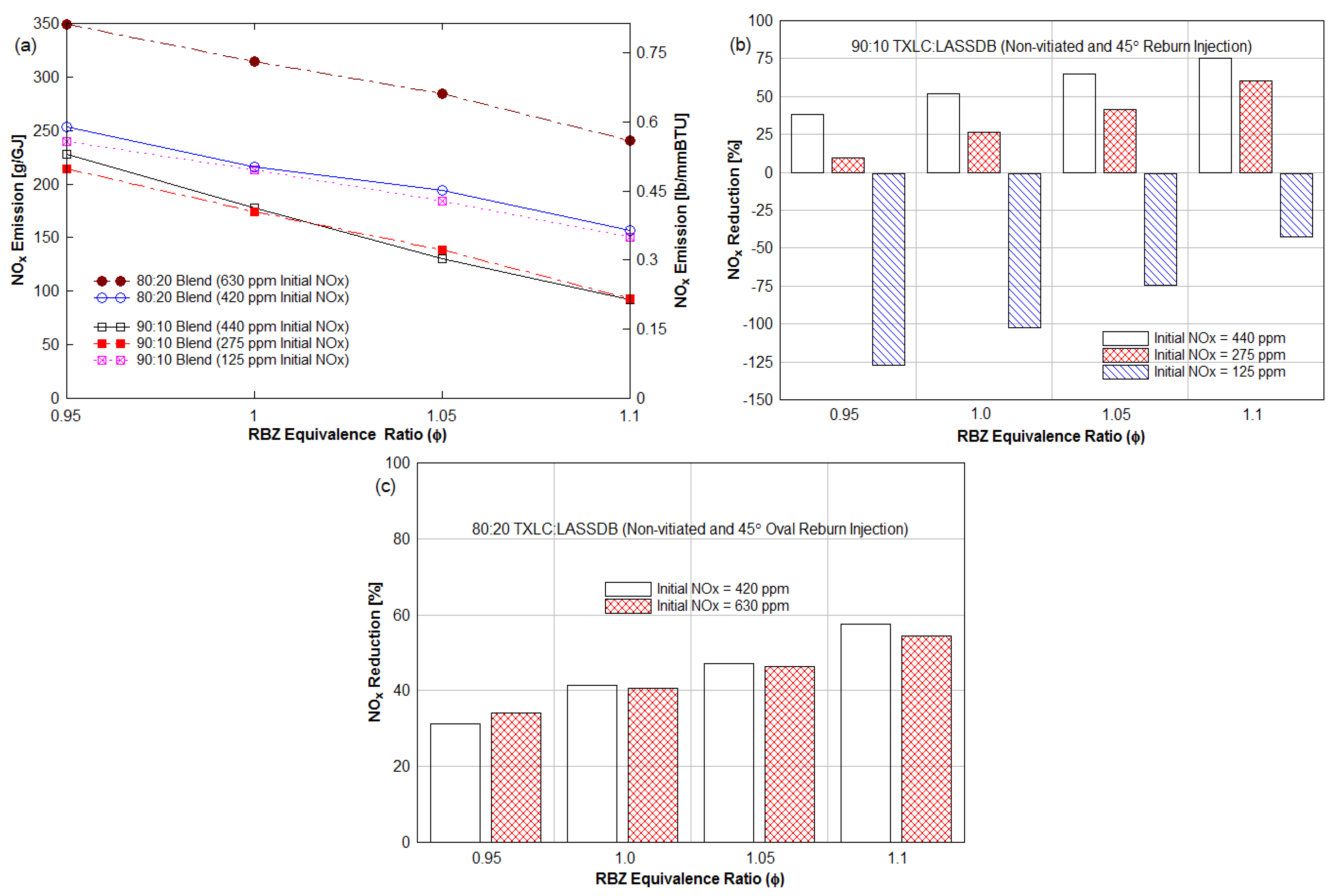
3.3.5. Effects of Initial NOx Concentration

Figure 12 shows the effect of the initial NOx produced by primary fuel combustion in the conditions of the non-vitiation, 30% heat input and 45° injection. The 45° circular reburn injector was used for 90:10 TXLC:LASSDB and the 45° oval injector (with oval cross-section) was used for 80:20 TXLC:LASSDB. For the 90:10 blends with the initial NOx of 440 and 275 ppm (Figure 12a), NOx emissions were remarkably similar and decreased from 228 to 92 g/GJ and 215 to 93 g/GJ, respectively. Their NOx reductions, however, increased from 38 to 75% and 9 to 61%, respectively, with an increase in ERRBZ as shown in Figure 12b. About 14 to 29% offset in NOx reduction was found between the 440 and 275 ppm cases, and lower NOx reductions were found with the lower initial NOx case.
Unlike the 90:10 blends, no significant difference was found between 630 and 420 ppm for the 80:20 blends. Though the 630 ppm case showed higher NOx emissions than the 420 ppm case, their offset in NOx reduction was found to be about 3% for all ERRBZ shown in Figure 12c. These results indicated NOx reductions took place with high initial NOx concentrations (i.e., 275, 420, 440, and 630 ppm), while NOx formations took place with the low initial NOx concentration (i.e., 125 ppm). The change in NOx reduction was not significant with initial NOx of about 400 ppm or higher, but it was significant with initial NOx less than 400 ppm.
The 125 ppm case showed a decrease in the NOx emission from 240 to 151 g/GJ; negative NOx reductions (or NOx formations) were measured as 128% at ERRBZ = 0.95 and 43% at ERRBZ = 1.1, as shown in Figure 12b. It indicated NOx was formed instead of reduced during reburning due to the extremely low concentration of NO in the RBZ. Initial NOx is treated as a parameter. When there is too much NH3 but low baseline NOx, then there is excess NH3, which oxidizes, and hence, increases NOx at slightly lean conditions in the reburn zone, i.e., negative “NOx” reduction. These results show good agreement with previous findings in [5]. NOx reduction typically takes place when NOx molecules collide and react with NH3 derived from fuel-N during fuel combustion. If order of NOx reduction reaction is proportional to NO concentration (i.e., collisional frequency), the rate of NOx reduction is slowed down, and hence, there is insufficient time in the elevated temperature zone for NOx reduction to proceed. Unlike the NOx species that are present in trace amounts, more O2 is available in the RBZ to react with NH3 to form NOx. Therefore, NOx formations took place in the case of the initial NOx of 125 ppm.
Wargadalam et al. studied NOx formations during HCN and NH3 oxidation with high oxygen concentrations at 870 to 1270 K and found about 22% HCN and 40% NH3 were converted to NOx by the addition of 1250 ppm CO at 1270 K [40].
In the 125 ppm (90:10 blend) case, concentrations of O2 [%], NOx [ppm] and CO2 [%] were higher than those in the 440 ppm (90:10 blend) case, but concentrations of CO [%] were lower. The CO concentrations in the 440 ppm case were found to be about 3700 to 8500 ppm more than those in the 125 ppm case, depending on the ERRBZ. Based on the results reported by Wargadalam et al., 3700–8500 ppm of CO was used for the NOx formation during HCN and NH3 oxidation in the 125 ppm case, and it resulted in 43% to 128% more NOx emission compared to its initial NOx concentration. Between 440 and 275 ppm cases, up to 1800 to 5000 ppm more CO was found in the 440 ppm NOx case, and these CO concentrations reduced NOx reduction in the 275 ppm case.
These results reveal reburning coal and DB is a highly effective technology on the NOx emission control with initial NOx emissions higher than 275 ppm (or 230 g/GJ and 0.5 lb/MMBtu). It should be carefully considered for designing boilers with low-NOx burners and reburn systems together due to lower NOx reduction efficiency and even NOx formation.

3.4. CO and Other Gas Emissions

Gas emissions of CO, CO2, SO2, and CxHy were measured along with the NOx emissions and the results are summarized.

3.4.1. CO Emission

During the reburn process, the fuel-rich environment causes high CO emissions but also results in lower NOx emissions. Thus, CO emissions increased with an increase in ERRBZ. High CO emissions in the fuel-lean combustion (ϕRBZ = 0.95) were measured due to the short residence time that caused incomplete combustion.
Figure 13a shows the effect of the reburn fuels on CO emissions in the conditions of the 30% reburn heat input and 0° reburn injection. The biomass fuels have a higher amount of VM (volatile matter), and hence, a higher amount of CO due to the presence of O2 in the fuel than both blends of coal: biomass and coal-only fuels. Thus, higher CO concentrations were produced by biomass-only fuels. This is consistent with our previous findings that the burnt fraction (BF) or, more rigorously, the gasification fraction, increased with an increase in the proportion of biomass in reburn fuels due to higher VM, which is released within a brief period.
Figure 13b presents the effect of the reburn injection (oval and circular at 45°) and vitiation on CO emissions. The results showed the 45° upward reburn injection produced more CO emissions due to it increasing the residence time, which resulted in combustion of more fuel particles in the RBZ. In the fuel-rich combustion, CO emissions typically increase while NOx emissions decrease with an increase in ERRBZ. Typically, the reburn zone is slightly operated under fuel-rich conditions for the reduction of NOx, and the NOx from combustion of fossil fuels decreases with the increase in CO. Both the residence time limitation and fuel-rich RBZ results in emissions of CO. While fuel-rich conditions reduce NOx, it increases CO.

3.4.2. CO-NO Emission Correlation

The literature reveals an inverse correlation between CO and NO. In fuel rich combustion, CO produced more but NO produced less than fuel lean combustion due to reduced local O2 concentrations and vice versa [41]. Thus, CO was measured, and a plot of NO vs. CO was obtained. Figure 13c indicates strong correlation for CO vs. NO for several reburn fuels and different operational conditions and showed a linear relation between CO and NOx emissions. There appears to be a strong correlation for all wide-ranging parameters studied here.

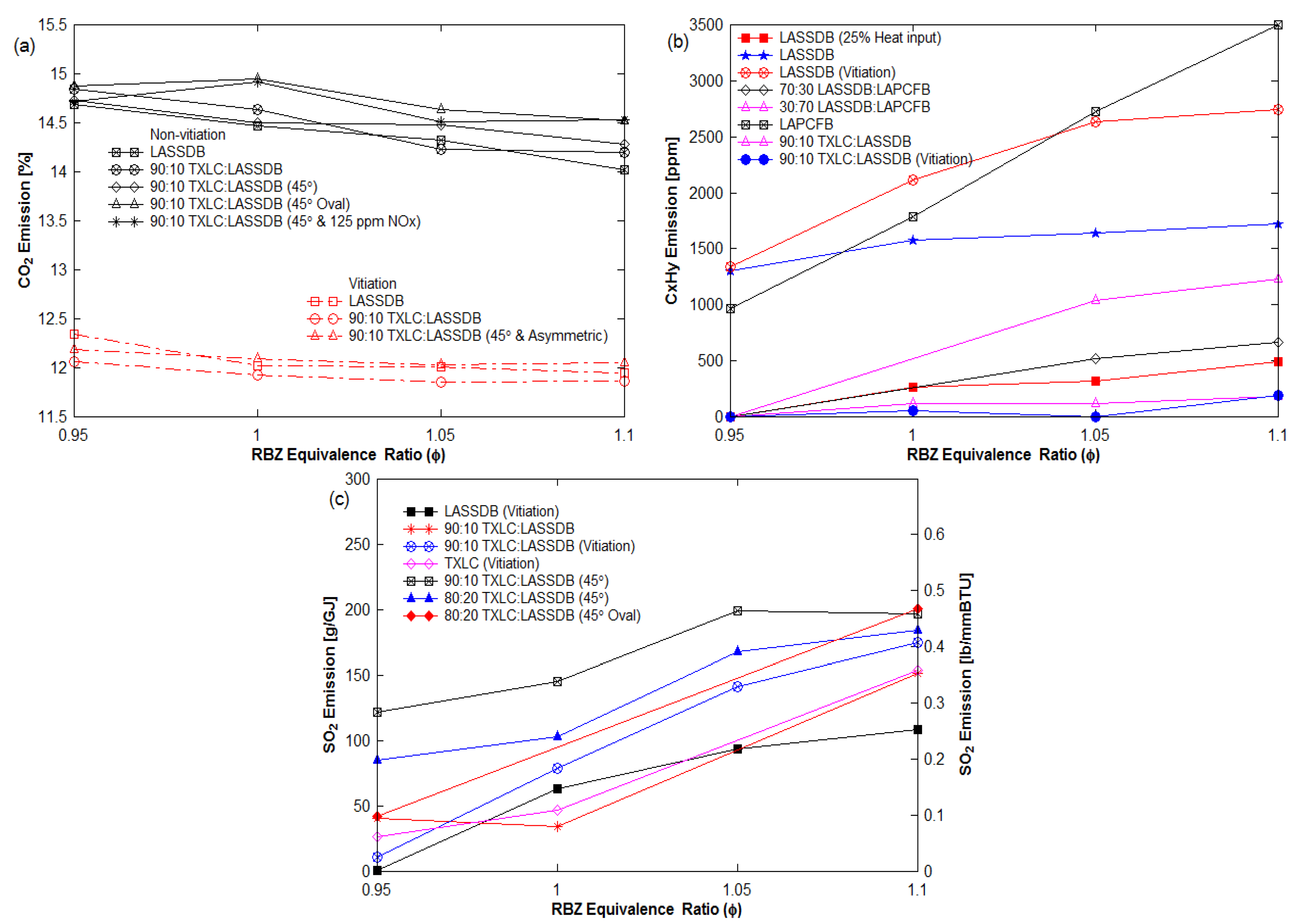
3.4.3. Other Emissions

The CO2 emission tendency showed the opposite to that of CO emissions. In Figure 14a, CO2 emissions decreased with an increase in ERRBZ. It is also noted that the N2 addition for the vitiation cases diluted the level of CO2, thus the CO2 concentrations for non-vitiation cases were higher.
The CxHy (unburned hydrocarbons) emissions increased with the increase in ERRBZ, as shown in Figure 14b. CxHy is typically burned to CO2 or water with enough oxygen. When the ERRBZ increases, the depletion of O2 causes less combustion of CxHy and produces less CO2 and water. The results showed the combustion of biomass-only fuels produced much more CxHy than the other reburn fuels. The results of the other fuels, blends of coal: biomass and coal-only fuels showed less than 100 ppm independent of the ERRBZ.
The measurement of SO2 was interfered with by water condensed in the probe of the gas analyzer. Stable measurements of SO2 emissions were presented in Figure 14c. The SO2 emissions increased with the increase in ERRBZ. Since SO2 is readily soluble to the cold water, more SO2 emissions should be detected in the lower water production case. With the increase in ERRBZ, less water was produced from CxHy; hence, a higher level of SO2 was detected.

3.5. Burnt Fraction (BF)

The variation in ER in RBZ causes a change in BF of the reburn fuels due to the change in proportions of moisture, ash, and combustibles (volatile matter and fixed carbon). Proximate and ultimate analyses for reburn fuels are presented in Table 2. Combustibles in fuels are 80.03% for LASSDB, 79.47% for LAPCFB and 81.41% for TXLC on a dry basis. In order to determine the BF, the bottom ash was collected from the ash port filled with water at the furnace bottom. The BF is defined as the ratio of combustibles burnt to the initial combustible mass. The BF was determined on a dry basis using the ash tracer method, which uses the % ash in RF prior to and after combustion [36].
The results of the BF are listed in Table 7: 64.15% for pure TXLC, 65.78% for 90:10 TXLC:LASSDB, 70.39% for 80:20 TXLC:LASSDB, 85.29% for LASSDB, and 88.90% for LAPCFB. The majority of lighter fly ash particles in the gas stream flowed into the exhaust duct, and most of the heavy solid particles dropped into the water in the ash port. Thus, the bottom ash collected from the ash port contained most of the heavy particles, and the BF calculated by the analysis of the heavy ash particles can be low. For the accurate BF estimation, both light fly ash and heavy bottom ash produced during the same period should be analyzed. It is found that the BF increased with the increase in the proportion of DB in reburn fuels. This is because DB has higher volatile matter (almost 80% on a DAF basis), and its particle sizes are smaller compared to TXLC. The burnt fraction of LASSDB was lower than the BF of LAPCFB, since LASSDB contained larger particles than LAPCFB.

4. Summary and Conclusions

Reburning coal with CB focuses on investigating the reduction in NOx emissions in the bench-scale (30 kW or 100,000 BTU/h) Boiler Burner Research Facility and determining the optimum operating condition of coal-fired boilers for the best NOx reduction. Parameters for reburn investigated are (a) fuel type, (b) equivalence ratio (ERRBZ or ϕRBZ), (c) reburn heat input, (d) degree of vitiation reburn, (e) injection angle, and (f) initial NOx concentration.
  • The extent of NOx reduction was found to be strongly dependent on the ERRBZ, with a 96% reduction in fuel-rich combustion in the reburn zone with DB as the reburn fuel.
  • NOx reduction increased with an increase in LASSDB proportion in reburn fuels, but ash % also increased. About 65 to 90% reduction is achieved for the 20% heat input with minimal ash production.
  • Vitiated reburn air (12.5% O2) increased NOx reductions and % reduction is higher with higher ERRBZ.
  • Results for the 45° upward injection provided the best NOx reduction.
  • When the initial NOx was of the order of 125 ppm, negative NOx reductions (or NOx formations) took place with reburning.
  • Optimum conditions are as follows: Initial NOx emissions higher than 275 ppm (or 127 g/GJ and 0.3 lb/MMBtu), 20% heat input by DB as the reburn fuel, and ERRBZ = 1.1.
  • The BF increased with the increase in proportion of DB in the reburn fuels.

5. Future Work

Cattle biomass, especially LASSDB and LAPCFB, can serve as very effective reburn fuel for the NOx emission control in coal-fired power plants. Future studies must explore opposed injection geometry to increase residence time within the reburn zone and future pilot scale tests must be performed with overfire air. Due to the limited availability of CB fuel, one may require future studies on smaller capacity coal-fired units between 50 and 300 MW. While the selected fuels are all derived from animal manure, other types of animal biomass including animal carcasses could be included as fuels. Since CB contains Cl, Hg could be oxidized with Cl and captured; thus, Hg reduction studies must be performed in addition to NOx reduction studies. The CB contains phosphorus (through feed ration to cattle), which may be oxidized during combustion. Possible corrosion studies on HEX must be performed.

6. Patents

As a result of the initial results from cofiring and reburn experiments with cattle biomass as cofired and reburn fuel for reduction of NOx produced from combustion of N containing main burner fuels such as coal, Annamalai, K. and Sweeten, B obtained US patent on, “Reburn System with Feedlot Biomass” US Patent # 6,973,883, 13 December 2005. Accessed on 14 October 2021 at http://www.patentstorm.us/patents/6973883-fulltext.html.

Author Contributions

Conceptualization, H.O.; Data curation, K.H.; Formal analysis, K.A. and J.M.S.; Funding acquisition, K.A. and J.M.S.; Investigation, H.O.; Methodology, H.O.; Project administration, K.A. and J.M.S.; Resources, J.M.S. and K.H.; Software, K.A.; Supervision, K.A. All authors have read and agreed to the published version of the manuscript.

Funding

This work was supported in part by the U.S. Department of Energy (Pittsburgh Energy Technology Center (DE-FG26-00NT40810) and Golden Field Office (DOE-FG26-05GO85003, DOE-FG26-05GO85003), and the Texas Commission on Environmental Quality (TCEQ Grant # 582-5-65591 0015).

Institutional Review Board Statement

Not applicable since the studies involved only wastes from animals.

Informed Consent Statement

Not applicable.

Data Availability Statement

Partly based on the PhD Thesis of Hyukjin Oh.

Acknowledgments

This work was supported in part by the U.S. Department of Energy (Pittsburgh Energy Technology Center and Golden Field Office), and the Texas Commission on Environmental Quality (TCEQ). The authors wish to thank Jerald Caton, Mechanical Engineering, Texas A&M for many fruitful discussions on NO formation and destruction.

Conflicts of Interest

The authors declare no conflict of interest.

Abbreviations

AFTAsh Fusion Temperature
AgBAgricultural Waste based Biomass Fuels
AnBAnimal Waste based Biomass Fuels
As Rec.As Received
B/ABasic to acidic oxide ratio
CBCattle Biomass (or Cattle manure)
DAFDry Ash Free
DBDairy Biomass
EFEnergy Fraction
EREquivalence Ratio or ϕ
FBFeedlot Biomass
FGRFlue Gas Recirculation
HAPCFBHigh Ash Partially Composted Feedlot Biomass
HEXHeat Exchanger
HHVHigher Heating Value
IDTInitial Deformation Temperature
LAPCFBLow Ash Partially Composted Feedlot Biomass
LASSDBLow Ash Separated Solids Dairy Biomass
RBZReburn Zone
RFReburn Fuel
RQRespiratory Quotient, {=CO2 moles/Stoichiometric O2 moles}
RZReburn Zone
SATPStandard Ambient Temperature and Pressure
SCFHStandard Cubic Feet per Hour
SCRSelective Catalytic Reduction
SMDSauter Mean Diameter
TAMUTexas A&M University
TXLCTexas Lignite Coal
UCFUnit Carbon Formula
WYCWyoming Sub-bituminous Coal

Appendix A. Estimation of Required NH3 Injection for Simulating NO and Reburn Fuel Flow Rates

Appendix A.1. Main Burner Modeling

The main burner fuel is assumed to be represented by the formula CH x O y N z which is burned along with some NH3 to simulate the desired amount of NO. The amount of ammonia to be fired with the fuel is adjusted in order to achieve the desired amount of NO. The solution for complete combustion of a general fuel is:
C H x O y N z + w · N H 3 + ( 1 + a 100 ) · ( 1 + x 4 y 2 + 5 w 4 ) · ( O 2 + 3.76 · N 2 )   C O 2 + ( x 2 + 3 · w 2 ) · H 2 O + + a 100 · ( 1 + x 4 y 2 + 5 w 4 ) · O 2 + w · N O + [ z 2 + 3.76 · ( 1 + a 100 ) · ( 1 + x 4 y 2 + w 2 ) ] · N 2
where a is the percentage of excess air based on the main burner fuel only. If the excess air is fixed at 5% or if the equivalence ratio is known, then a is known. Note that typically “w” is small, and hence, % excess air can also be based on the main fuel alone. In the experiments, the NOx local concentration at the exit of the main burner has been fixed at 400 ppm on a dry basis, which is a typical value used in reburn experiments [27,28], in which the reburn fuel is injected in a gas stream that contains a significant amount of NO. Note that there is some thermal NO that is not included in the formulae of Equation (A1).
Even if there was some thermal NOx, this would not have much effect on the overall model as simply less ammonia would be injected in the main burner. Therefore, on a dry basis:
X N O x = 400 · 10 6 = w 1 + w + a 100 ( 1 + x 4 y 2 + 5 w 4 ) + [ z 2 + 3.76 · ( 1 + a 100 ) · ( 1 + x 4 y 2 + 5 w 4 ) ]
Solving for “w”
w = Moles   NH 3   fired Moles   of   MF   = X N O x { 1 + a 100 · ( 1 + x 4 y 2 ) + [ z 2 + 3.76 · ( 1 + a 100 ) · ( 1 + x 4 y 2 ) ] } [ 1 X N O x { 1 + 5 a 400 + 5 3.76 4 ( 1 + a 100 ) } ]
The XNOx represents the mole fraction of NO created by oxidation of NH3 while total NOx is a sum of thermal NOx and fuel NOx. Note that typically X N O x { 1 + a 200 + 1.88 ( 1 + a 100 ) } 1 in denominator. Thus, it is possible to compute w since a is known. Now, the amount of air and ammonia to be injected in the main burner fuel can be calculated and also the composition of the products coming from the main burner is known.
V ˙ f u e l   M B ( m 3 s ) = T h e r m a l   R a t i n g M B ( k W ) H H V f u e l   M B ( k J / m 3 )       o r       m ˙ f u e l   M B ( k g s ) = T h e r m a l   R a t i n g M B H H V f u e l   M B ( k J / k g )
As the thermal power coming from the main burner is fixed (70% of the total thermal power of the facility), it is possible to compute the mass flow of the main burner fuel:
V ˙ N H 3 ( m 3 s ) =         w   (   m 3       o f     N H 3 m 3       o f     N G   )     V ˙ M F ( m 3 s )     o r       m ˙ a m m o n i a ( k g k g     f u e l     s ) = w M N H 3 M M F
Therefore, the firing rate of ammonia is given by:
The total moles of NO { N ˙ NOMB} leaving the main burner
N ˙ N O M B = w     x T h e r m a l   R a t i n g M B H H V ¯ f u e l   M B [ k m o l e     o f     N O s ]    

Appendix A.2. Reburn Fuel Flow Rate

Additionally, the reburn fuel is known in the generic form of C H x 1 O y 1 N z 1 S s 1 . The reburn fuel is assumed to be a solid fuel; therefore, it is necessary to model the release of volatiles and FN. The chemical formula is obtained from the ultimate analysis (dry ash free), normalizing the carbon atom content to one. The composition of the FN gas stream is assumed from the literature.
C H x 1 O y 1 N z 1 S s 1 a · C ( s ) + b · C O + c · C O 2 + d · C H 4 + e · H C N + f · N H 3 + g · N 2 + s 1     S O 2
where b = 0 under complete combustion. The mass/mole flow rate of the reburn fuel is computed knowing the heat input of the re-burner and the heating value of the fuel. For the general case of a blend, Ycoal and YDB are defined as the mass fractions of coal and DB. For the general case of a blend, Ycoal and YFB are defined as the mass fractions of the two fuels. For any reburn fuel fired into RZ, required flow rate of fuel is given as:
m ˙ f u e l   R Z     [ k g f u e l s ]   = Re b u r n T h e r m a l   P o w e r R Z , k W H H V f u e l   ( k J k g )   o r       N ˙ f u e l   R Z = Re b u r n T h e r m a l   P o w e r R Z H H V ¯ f u e l   [ k m o l e f u e l s ]
Expressing in terms of fuel firing rate of main fuel {MF} and energy fractions (EF):
Mass   Ratio ,   β =   m ˙ RF       m ˙ MF   = { EF RF EF MF } HHV MF     HHV RF   = α     HHV MF     HHV RF  
If HHVO2 is constant
Mass   Ratio ,   β =   m ˙ RF       m ˙ MF   = { EF RF EF MF } ν RF ν MF   = α     ν RF ν MF  
where ν is in stoichiometric of O2 in kg per kg fuel.

References

  1. Frazzitta, S.; Annamalai, K.; Sweeten, J. Performance of a Burner with Coal and Coal-Bio-Solid Fuel Blends. J. Propuls. Power 1999, 15, 181–186. [Google Scholar] [CrossRef]
  2. Johnson, D.K.; Engelhardt, D.A.; Harvilla, J. Clean Coal Technology—Reburning Technologies for the Control of Nitrogen Oxides Emissions from Coal—Fired Boilers; Topical Report Number 14; U.S. Department of Energy: Washington, DC, USA, 2007. Available online: www.fossil.energy.gov/programs/powersystems/publications/Clean_Coal_Topical_Reports/ (accessed on 14 October 2021).
  3. Adams, B.R.; Harding, N.S. Reburning using Biomass for NOx Control. Fuel Process. Technol. 1998, 54, 249–263. [Google Scholar] [CrossRef]
  4. Spliethoff, H.; Hein, K.R.G. Effect of Co-Combustion of Biomass on Emissions in Pulverized Fuel Furnaces. Fuel Process. Technol. 1998, 54, 189–205. [Google Scholar] [CrossRef]
  5. Arumugam, S. Nitrogen Oxides Emission Control through Reburning with Biomass in Coal-Fired Power Plants. Master’s Thesis, Mechanical Engineering, Texas A&M University, College Station, TX, USA, 2004. [Google Scholar]
  6. Yang, Y.B.; Naja, T.A.; Gibbs, B.M.; Hampartsoumian, E. Optimisation of Operating Parameters for NO Reduction by Coal Reburning in a 0.2 MW Furnace. J. Inst. Energy 1997, 70, 9–16. [Google Scholar]
  7. Brouwer, J. Cofiring Waste Biofuels and Coal for Emissions Reduction. Fuel Energy Abstr. 1995, 36, 437. [Google Scholar]
  8. Maly, P.M.; Zamansky, V.M.; Ho, L.; Payne, R. Alternative Fuel Reburning. Fuel 1999, 78, 327–334. [Google Scholar] [CrossRef]
  9. Zamansky, V.M.; Maly, P.M.; Lissianski, V.V.; Freeman, M.C. Advanced Biomass Reburning. Report. Department of Energy ad Agriculture. 2000. Available online: www.netl.doe.gov/publications/proceedings/98/98ps/pspa-5.pdf (accessed on 14 October 2021).
  10. Sweterlitsch, J.J.; Brown, R.C. Fuel Lean Biomass Reburning in Coal-Fired Boilers; Final Technical Report; DOE Award No: DE-FG26-00NT40811; Center for Sustainable Environmental Technologies, Iowa State University: Ames, IA, USA, 2002. [Google Scholar]
  11. Annamalai, K.; Sweeten, J.M.; Mathur, M.; Thien, B.; Wei, G.; Priyadarsan, S.; Arumugam, S.; Heflin, K. Co-Firing Coal: Feedlot and Litter Biomass (CFB and CLB) Fuels in Pulverized Fuel and Fixed Bed Burners; Final Report; National Energy Technology Laboratory, and Department of Energy: College Station, TX, USA, 2003. Available online: www.osti.gov/bridge/servlets/purl/822025-otOX2Z/native/822025.pdf (accessed on 14 October 2021).
  12. Storm, C.; Spliethoff, H.; Hein, K.R.G. Generation of a Gaseous Fuel by Pyrolysis of Biomass and Sewage Sludge for Use as Reburn Gas in Coal-Fired Boilers. Clean Air 2005, 6, 289–328. [Google Scholar] [CrossRef]
  13. Annamalai, K.; Goughnour, P.G.; Oh, H.; Arcot, V.U.; Sweeten, J.M. NOx and Hg Capture Using Coal, Feedlot Biomass (Cattle Manure) as Reburn Fuels—Task 2: Reburn Experiments for NOx and Hg Reduction; Final Report; College Staion: Mech Eng., Texas A&M; Texas Commission on Environment (TCEQ): Austin, TX, USA, 2006. [Google Scholar]
  14. Hall, R.E.; Miller, C.A.; Payne, R.; Yakushin, E.; Mespan, J. Application of Multifuel Reburn for NOx Control on a 300 MWe Boiler in Ukraine. In Proceedings of the Air & Waste Management Association’s Annual Meeting & Exhibition, Nashville, TN, USA, 23–28 June 1996; pp. 1–13. [Google Scholar]
  15. Flosom, B.A.; Engelhardt, D.A.; Moyeda, D.K.; Chang, S.S.; Janik, G.S.; Whelan, M.P. Gas Reburning and Advanced Gas Reburning for NOx Emissions Control. In Proceedings of the 90th Annual Meeting and Exhibition at Air and Waste Management Association, Toronto, ON, Canada, 8–13 June 1997. [Google Scholar]
  16. Lissianski, V.V.; Zamansky, V.M.; Maly, P.M. Effect of Metal-Containing Additives on NOx Reduction in Combustion and Reburning. Combust. Flame 2001, 125, 1118–1127. [Google Scholar] [CrossRef]
  17. Patsias, A.A.; Nimmo, W.; Gibbs, B.M.; Williams, P.T. Calcium-Based Sorbents for Simultaneous NOx/SOx Reduction in a Down-Fired Furnace. Fuel 2005, 84, 1864–1873. [Google Scholar] [CrossRef]
  18. Oh, H.; Annamalai, K.; Goughnour, P.G.; Thien, B.; Sweeten, J.M. Reburning Of Animal Waste Based Biomass With Coals For Nox Reduction, Part I: Feedlot Biomass (FB) And Coa:FB Blends. Energies 2021, in press. [Google Scholar]
  19. Liesa, F.; Alzueta, M.U.; Millera, A.; Bilbao, R. Influence of Reactant Mixing in a Laminar Flow Reactor: The Case of Gas Reburning. 1. Experimental Study. Ind. Eng. Chem. Res. 2007, 46, 3520–3527. [Google Scholar] [CrossRef]
  20. Oluwoye, I.; Zeng, Z.; Mosallanejada, S.; Altarawnehd, M.; Gore, J.; Dlugogorskif, B.G. Controlling NOx emission from boilers using waste polyethylene as reburning fuel. Chem. Eng. J. 2021, 411, 128427. [Google Scholar] [CrossRef]
  21. Li, S.; Xu, T.; Zhou, Q.; Tan, H.; Hui, S.; Hu, H. Optimization of Coal Reburning in a 1 MW Tangentially Fired Furnace. Fuel 2007, 86, 1169–1175. [Google Scholar] [CrossRef]
  22. Miller, C.A.; Touati, A.D.; Becker, J.; Wendt, J.O.L. NOx Abatement by Fuel-Lean Reburning: Laboratory Combustor and Pilot-Scale Package Boiler Results. In Symposium (International) on Combustion; Elsevier: Amsterdam, The Netherlands, 1998; pp. 3189–3195. [Google Scholar]
  23. Lawrence, B.; Annamalai, K.; Sweeten, J.M.; Heflin, K. Cofiring Coal and Dairy Biomass in a 29 kWt Furnace. J. Appl. Energy 2009, 86, 2359–2372. [Google Scholar] [CrossRef]
  24. Patumsawad, S.; Cliffe, K.R. Experimental Study on Fluidized Bed Combustion of High Moisture Municipal Solid Waste. Energy Convers. Manag. 2002, 43, 2329–2340. [Google Scholar] [CrossRef]
  25. Savolainen, K. Co-Firing of Biomass in Coal-Fired Utility Boilers. Appl. Energy 2003, 74, 369–381. [Google Scholar] [CrossRef]
  26. Sweeten, J.M.; Annamalai, K.; Thien, B.; McDonald, L.A. Co-Firing of Coal and Cattle Feedlot Biomass (FB) Fuels. Part I. Feedlot Biomass (Cattle Manure) Fuel Quality and Characteristics. Fuel 2003, 82, 1167–1182. [Google Scholar] [CrossRef]
  27. Thien, B.; Annamalai, K. Reduction of NO through Reburning with Coal and Feedlot Biomass. In Proceedings of the National Combustion Conference, Oakland, CA, USA, 25–27 March 2001. [Google Scholar]
  28. Annamalai, K.; Thien, B.; Sweeten, B. Co-Firing of Coal and Cattle Feedlot Biomass (FB) Part II. Performance Results from 30 kW (100,000) BTU/h Laboratory Scale Boiler Burner. Fuel 2003, 82, 1183–1193. [Google Scholar] [CrossRef]
  29. Annamalai, K.; Sweeten, J.; Freeman, M.; Mathur, M.; O’Dowd, W.; Walbert, G.; Jones, S. Co-Firing of Coal and Cattle Feedlot Biomass (FB) Fuels, Part III: Fouling Results from a 500,000 BTU/h Pilot Plant Scale Boiler Burner. Fuel 2003, 82, 1195–1200. [Google Scholar] [CrossRef]
  30. Annamalai, K.; Sweeten, J.M.; Martin, B. Pyrolysis, Ignition, and Fuel Characteristics of Coal, Feedlot Biomass, and Coal: Feedlot Biomass Blends; Final Report to Texas Commission on Environmental Quality (TCEQ). 2006. Available online: http://search.tceq.state.tx.us/ (accessed on 14 October 2021).
  31. Li, S.; Wu, A.; Deng, S.; Pan, W.P. Effect of co-combustion of chicken litter and coal on emissions in a laboratory-scale fluidized bed combustor. Fuel Process. Technol. 2008, 89, 7–12. [Google Scholar] [CrossRef]
  32. Qian, X. Statistical Analysis and Evaluation of the Advanced Biomass and Natural Gas Co-Combustion Performance. Ph.D. Dissertation, Morgan State University, Baltimore, Maryland, 2019. [Google Scholar]
  33. Annamalai, K.; Sweeten, B. Reburn System with Feedlot Biomass. US Patent #6,973,883, 13 December 2005. Available online: http://www.patentstorm.us/patents/6973883-fulltext.html (accessed on 14 October 2021).
  34. Sweeten, J.M. Composting Manure and Sludge; Texas Agricultural Extension Service: College Station, TX, USA, 2008; Publication L-2289. [Google Scholar]
  35. Eseltine, D.; Thanapal, S.S.; Annamalai, K.; Ranjan, D. Torrefaction of Woody Biomass Using Inert and Non-Inert Gases. Fuel 2013, 113, 379–388. [Google Scholar] [CrossRef]
  36. Annamalai, K.; Puri, I.K. Combustion Science and Engineering; CRC Press: Boca Raton, FL, USA; Taylor & Francis: Boca Raton, FL, USA, 2007. [Google Scholar]
  37. Annamalai, K.; Thanapal, S.; Ranjan, D. Ranking renewable and fossil fuels on global warming potential using respiratory quotient (RQ) Concept. J. Combust. 2018, 2018, 1270708. [Google Scholar] [CrossRef] [Green Version]
  38. Meesuk, S.; Cao, J.P.; Sato, K.; Hoshino, A. Nitrogen Conversion of Pig Compost during Pyrolysis. J. Chem. Eng. Jpn. 2013. [Google Scholar] [CrossRef]
  39. Soyuz, P. Reburn Studies for Hg and NOX Reduction in Coal Fired Burners. Ph.D. Thesis, Texas A&M University, Mechanical Engineering, College Station, TX, USA, 2007. Posthumous. [Google Scholar]
  40. Wargadalam, V.J.; Loffler, G.; Winter, F.; Hofbauer, H. Homogeneous Formation of NO and N2O from the Oxidation of HCN and NH3 at 600–1000 °C. Combust. Flame 2000, 120, 465–478. [Google Scholar] [CrossRef]
  41. Roberge, B. Effect of Varying the Combustion Parameters on the Emissions of Carbon Monoxide and Nitrogen Oxides in the Exhaust Gases from Propane Fueled Vehicles. Appl. Occup. Environ. Hyg. 2000, 15, 421–428. [Google Scholar] [CrossRef] [PubMed]
Figure 1. Conventional, vertically upward-fired coal fired burner for the reburn technology [2].
Energies 14 08076 g001
Figure 2. A schematic of the bench-scale (30 kW or 100,000 BTU/h) down-fired boiler burner facility.
Energies 14 08076 g002
Figure 3. Injection configurations of reburn fuels: (a) Symmetric lateral (0°) injection, (b) Symmetric 45° upward injections and (c) Asymmetric 45° upward injection with air and N2.
Energies 14 08076 g003
Figure 4. Particle size (Rosin-Rammler) distributions of the reburn fuels. Cumulative Mass %, D = 100 {1 − exp(−bdpn)}, see Chapter 4 of Ref. [36], y = ln {−ln{1 − (D/100)}, x = ln(dp), y = nx + A, A = ln(b). Data fit for TXLC yields A = −6.9762, n = 1.2991. Similar procedure for LAPCFB and LASSDB.
Energies 14 08076 g004
Figure 5. (a) Temperature distribution of the flue gas in the reactor over axial distance and (b) Temperature distribution of the flue gas in the reactor over radial distance.
Energies 14 08076 g005
Figure 6. Pyrolysis results using TGA for different particle sizes of LASSDB: (a) weight % vs. time with particle size as the parameter and (b) weight % vs. temperature with particle size as the parameter.
Energies 14 08076 g006
Figure 7. Moisture and volatile released during pyrolysis using TGA for different particle sizes of all fuels: (a) Particle size vs. time and (b) Particle size vs. temperature.
Energies 14 08076 g007
Figure 8. NOx control with the reburn fuels (non-vitiation, 30% reburn heat input and 0° reburn injection): (a) NOx emission and (b) NOx reduction on a heat basis.
Energies 14 08076 g008
Figure 9. NOx emission with the blends of DB and FB (non-vitiation, 30% heat input and 0° injection).
Energies 14 08076 g009
Figure 10. Effect of the vitiated reburn air (30% reburn heat input and 0° reburn injection): (a) NOx emission and (b) NOx reduction on a heat basis.
Energies 14 08076 g010
Figure 11. Effect of the reburn heat input using LASSDB (non-vitiation and 0° reburn injection).
Energies 14 08076 g011
Figure 12. Effect of the initial NOx produced by primary fuel combustion (non-vitiation, 30% heat input and 45° injection): (a) NOx emissions (90:10 blends for the circular injection and 80:20 blends for the oval injection (with oval shaped nozzle)), (b) NOx reductions % for 90:10 blends and (c) NOx reductions % for 80:20 blends.
Energies 14 08076 g012
Figure 13. CO emissions: (a) Effect of the reburn fuels, (b) Effect of the reburn injection, and (c) Variation of CO with NOx emissions. Polynomial fit is also presented within figure. y = CO %, x= NOx in g/GJ.
Energies 14 08076 g013
Figure 14. (a) CO2 emissions, (b) CxHy emissions and (c) SO2 emissions as a function of the ERRBZ.
Energies 14 08076 g014
Table 1. Literature review on reburn studies.
Ref.Boiler CapacityReburn Fuel (Heat Input)Fuel Particle Size (Reburn Temp.)Reburn SR (Main SR)Residence TimeMax. NOx Reduction (Baseline NOx)Conclusion
[3]265 MW + OFAWood
(15%)
80% 800 μm
(1900 K)
0.9
(1.05)
0.3–1.2 s60%
(~1300 ppm)
Wood was successfully used as a reburn fuel on NOx reduction using a cyclone fired boiler.
[4]Electric furnace + OFACH4, synthetic gas, pyrolysis gas of coalGas
(1300–1700 K)
0.65–1.15
(0.65–1.15)
1.2–3 s88%
(NA)
Pyrolysis gas was an effective reburn fuel. Longer residence time reduced NOx emissions.
[5]30 kWCB, coals, Coal:CB blends
(30%)
50–70% 100 μm
(1500 K)
0.83–1.0
(1.05)
0.4–0.9 s62%
(600 ppm)
Circular jet/flat spray reburn nozzles were tested, and CB resulted in higher NOx reduction than coal.
[6]200 kW + OFA and AGRBituminous coals
(10–35%)
75% 63 μm
(1600 K)
0.83–1.0
(1.0–1.18)
0.12–0.84 s65%
(600 ppm)
NOx reduction was strongly dependent on the reburn SR. The optimum reburn residence time was 0.45 s.
[7]38 kW + OFAWood
(10%)
100% 1680 μm
(1700 K)
0.85–1.05
(1.15)
0.4 s60%
(200–500 ppm)
Wood was an effective reburn fuel for a small-scale pulverized coal-fired furnace.
[8]300 kW + OFA and AGRBiomass, coals, CRDF
(10–20%)
70% 75 μm
(1700 K)
0.88–0.99
(1.1)
0.4–0.7 s91% (AR)
(200–1300 ppm)
Advance gas reburning (AGR) by the addition of N-agent with promoters greatly increased NOx reduction.
[9]300 kW + OFAWood, waste,
walnut shell, NG
(10–25%)
55% 75 μm
(1700 K)
0.84–0.99
(1.1)
0.82 s72%
(400–900 ppm)
NO reductions: NG walnut shell furniture waste willow wood
[10]35 kWSwitchgrass, alfalfa
(4–23%)
75% 1000 μm
(1600 K)
1.05–1.40.81 s70%
(500 ppm)
High N-containing fuel was successfully used as a reburn fuel in a fuel-lean combustion.
[11]30 kWFB, LB
(30%)
70–90% 75 μm
(1500 K)
0.91–1.0
(1.05)
1 s80%
(600 ppm)
FB and litter biomass (LB) were successfully used for co-firing, reburning and gasification.
[12]30 kW + OFAPyrolysis gas of sewage sludge, sawdust, etc.
(40%)
Gas
(1600 K)
0.75–1.15
(1.15)
2 s89%
(1000–1200 mg/m3)
Pyrolysis gas from biomass used as a reburn fuel contributed high NOx reduction and the net CO2 reduction.
[13]30 kWCB, coals,
Coal:CB blends
(30%)
60–90% 150 μm
(1500 K)
0.87–1.0
(1.05)
0.6–0.7 s95%
(400 ppm)
CB as a reburn fuel significantly reduced NOx emissions. NOx reductions strongly depended on the reburn equivalence ratio.
[14]300 MW + OFA and FGRNG, oil, coal
(15–20%)
80% 44 μm
(1800 K)
0.9NA65%
(600 ppm)
High NOx reductions with fine fuel particles.
[15]105 MW + OFA and AGRNG
(10–20%)
Gas
(1200–1400 K)
0.9NA70%
(0.62 lb/MMBtu)
AGR by the injection of N-agent significantly improved NOx reduction and CO emissions.
[16]300 kW + OFANG
(5–25%)
Gas
(1700 K)
0.83–1.05
(1.1)
0.82 s66%
(600 ppm)
Reburning with alkali compounds was effective in NOx reduction.
[17]80 kW + OFACarboxylic salts + C3H8
(9–20%)
NA
(1400 K)
0.86–1.03
(1.05)
NA80%
(NA)
The addition of carboxylic salts to propane as a reburn fuel improved the reburn process.
[18]30 kWFB, Coal:FB Blends
(30%)
60% 113 μm(0.95–1.15)0.6–0.7 s95%
(400 ppm)
Feedlot Biomass as reburn fuel with NG as main fuel
[19]Laminar flow reactorSynthetic gas
(CH4 + C2H6)
Gas
(900–1500 K)
0.6–2.00.8 s50%
(850 ppm)
Fuel mixing was effective for reburning due to the change in local stoichiometry and residence time.
[20]Entrained bed reactorPolyethylene150–355 μm0.8–1.20.45 s
(total 1 s)
up to 82%1000–1200 °C
[21]1 MW + LNB and OFACoals
(15–25%)
Micronized
Dmedian: 11–54 μm
(1600 K)
0.85–0.95
(1.05)
NA80%
(775–820 ppm)
Micronized fuels resulted in little increase in NOx reduction.
[22]17 kW and 0.9 MWNG
(7–25%)
Gas
(800–1100 K)
1.2
(1.2–1.3)
NA60%
(250–2600 ppm)
The fuel-lean reburning is an effective method to reduce NOx for lab- and pilot-scale boilers.
Table 2. Proximate and ultimate analyses for reburn fuels. Natural gas: CH4—94.3%, CO2—1.7%, C2H6—2.4%, N2—0.7%, C3H8—0.5%; empirical chemical formula: CH3.84N0.0086O0.032, M = 16.52, HHV—37,055 kJ/m3 (55,045 kJ/kg) [18].
ContentsTXLCLAPCFBLASSDB
As Rec.DryDAFAs Rec.DryDAFAs Rec.DryDAF
Moisture38.340019.640025.2600
Ash11.4618.59016.5020.53014.9319.970
Volatile Matter24.7940.2049.3852.3365.1181.9446.8662.7078.35
Fixed Carbon25.4141.2150.6211.5414.3618.0612.9517.3321.65
HHV, kJ/kg
(BTU/lb)
14,290
(6145)
23,170
(9960)
28,465
(12,240)
13,265
(5705)
16,505
(7095)
20,773
(8930)
12,845
(5520)
17,180
(7385)
21,475
(9230)
Carbon, C37.1860.3074.0733.7942.0552.9135.2047.0958.84
Hydrogen, H2.123.444.233.654.555.723.124.175.21
Nitrogen, N0.681.111.351.972.453.081.932.583.22
Oxygen, O9.6115.5819.1423.9429.7837.4919.1525.6232.01
Sulfur, S0.610.981.210.510.640.790.430.570.71
Table 3. Derived fuel properties for reburn fuels.
TXLCLAPCFBLASSDB
Stoich. Air: Fuel Ratio (A:F)4.634.144.32
Stoich. O2: Fuel Ratio (O:F)0.970.870.91
As Rec. HHV, kJ/kg (BTU/lb)14,290 (6145)13,265 (5705)12,845 (5520)
HHV in kJ per kg Stoich. Air (BTU/lb)3090 (1330)3210 (1380)2975 (1280)
HHV in kJ per kg Stoich.O2 (BTU/lb)14,710 (6325)15,275 (6565)14,170 (6090)
DAF HHV, kJ/kg (BTU/lb)28,465 (12,240)20,775 (8930)21,474 (9232)
Ash Loading kg/GJ8.0212.4411.62
VM-HHV, kJ/kg, Equations in Ref [35,36]24,05518,13018,355
VM heat contribution, %427267
VM HHV/DAF Fuel HHV0.8450.8730.855
Chemical FormulaCH0.68 N0.02 O0.19 S0.006CH1.28 N0.05 O0.53 S0.006CH1.06 N0.05 O0.41 S0.005
CFr, DAF0.740.530.59
M, DAF0.7422.6820.5
CFr Bl/HHVBl (GJ/kg)16.2117.1817.72
RQRF0.850.750.79
RQBl; see Ref [37] for blends with EFRF = 0.3 0.620.590.60
Table 4. Mineral analysis of ash (% mass, ash was calcined ≅ 1100 °F (600 °C) prior to analysis).
CompositionsTXLCLAPCFBLASSDB
Silicon, SiO248.7220.7831.36
Aluminum, Al2O316.044.942.89
Titanium, TiO20.850.220.2
Iron, Fe2O37.441.711.62
Calcium, CaO11.702126.4
Magnesium, MgO1.937.547.47
Sodium, Na2O0.295.262.28
Potassium, K2O0.6114.66.9
Phosphorus, P2O50.113.776.01
Sulfur, SO310.804.474.72
Chlorine, Cl0.015.070.92
Carbon dioxide, CO20.080.599.49
Basic oxides/Acidic oxides, B/A0.342.461.47
Table 5. Ash fusion behavior for reburn fuels.
PropertiesTXLCLAPCFBLASSDB
Reducing atmosphere
Initial deformation temperature, IDT or AFT, °F (°C)2111 (1155)2126 (1165)2153 (1178)
Softening temperature, ST, °F (°C)2150 (1175)2143 (1170)2169 (1187)
Hemispherical temperature, HT, °F (°C)2181 (1195)2148 (1175)2175 (1191)
Flow temperature, FT, °F (°C)2190 (1200)2156 (1180)2181 (1194)
Oxidizing atmosphere
Initial deformation temperature, IDT or AFT, °F (°C)2238 (1225)2124 (1160)2190 (1199)
Softening temperature, ST, °F (°C)2256 (1235)2186 (1200)2198 (1203)
Hemispherical temperature, HT, °F (°C)2276 (1245)2146 (1175)2201 (1205)
Flow temperature, FT, °F (°C)2310 (1265)2154 (1180)2206 (1208)
Table 6. Fuel particle size distributions.
Mean Dia. (μm)TXLC (w%)LASSDB (w%)
15960.0150.260
10150.020.841
5705.59521.815
22537.98631.451
11334.20422.880
6014.8579.602
22.57.32013.110
Mean size by mass (μm)166.84242.24
SMD (μm)94.7288.84
Table 7. Burnt fraction (BF) on a dry basis for the bottom ash of reburn fuels.
Reburn FuelAsh [%]Combustibles [%]Burnt Fraction [%]
LASSDB62.9137.0985.29
80:20 TXLC:LASSDB43.7756.2370.39
90:10 TXLC:LASSDB40.4659.5465.78
TXLC38.9161.0964.15
LAPCFB69.9430.0688.90
Publisher’s Note: MDPI stays neutral with regard to jurisdictional claims in published maps and institutional affiliations.

