Article

Technical Assessment of Hybrid HVDC Circuit Breaker Components under M-HVDC Faults

1
Department of Electrical Engineering, The University of Lahore, Lahore 54000, Pakistan
2
Department of Electrical Engineering, University of Engineering and Technology, Lahore 54000, Pakistan
3
Department of Electrical and Computer Engineering, King Abdulaziz University, Jeddah 21589, Saudi Arabia
4
School of Electrical Engineering, Guangxi University, Nanning 530600, China
5
Faculty of Engineering and Applied Science, Memorial University of Newfoundland, St. John’s, NL A1B 3X5, Canada
*
Author to whom correspondence should be addressed.
Energies 2021, 14(23), 8148; https://doi.org/10.3390/en14238148
Submission received: 3 November 2021 / Revised: 25 November 2021 / Accepted: 30 November 2021 / Published: 5 December 2021
(This article belongs to the Section F: Electrical Engineering)

Abstract

:
One of the technical challenges that needs to be addressed for the future of the multi-terminal high voltage direct current (M-HVDC) grid is DC fault isolation. In this regard, HVDC circuit breakers (DCCBs), particularly hybrid circuit breakers (H-DCCBs), are paramount. The H-DCCB, proposed by the ABB, has the potential to ensure a reliable and safer grid operation, mainly due to its millisecond-level current interruption capability and lower on-state losses as compared to electromechanical and solid-state based DCCBs. This paper aims to study and evaluate the operational parameters, e.g., electrical, and thermal stresses on the IGBT valves and energy absorbed by the surge arrestors within H-DCCB during different DC fault scenarios. A comprehensive set of modeling requirements matching with operational conditions are developed. A meshed four-terminal HVDC test bench consisting of twelve H-DCCBs is designed in PSCAD/EMTDC to study the impacts of the M-HVDC grid on the operational parameters of H-DCCB. Thus, the system under study is tested for different current interruption scenarios under a (i) low impedance fault current and (ii) high impedance fault current. Both grid-level and self-level protection strategies are implemented for each type of DC fault.

1. Introduction

Recently there has been an increased interest in developing a voltage source converter (VSC) based on multi-terminal high voltage direct current (M-HVDC) transmission grids. For this purpose, HVDC circuit breakers (DCCBs) are considered to be a vital component responsible for interrupting and isolating the DC fault current [1]. Owing to the low damping of the DC fault current in an HVDC grid, the initial rate of the rising fault current can reach the kA/ms range [2]. This results in various electrical and thermal stresses to be developed on the DCCB components and branches. These stresses may compromise, not only the DCCB’s operation, but also affect its operational performance. Studying these electrical, thermal, and energy absorption stresses would highlight the states of DCCB’s components under different DC fault conditions.
A multi-terminal HVDC (M-HVDC) grid system can be realized through the interconnection of various HVDC substations. However, most of the present HVDC systems consist of line commutated converters (LCC) forming point-to-point connections only. Though only a few M-HVDC systems exist today, their development is hugely restricted; this is mainly because of the lack of DC grid protection systems, particularly fast-acting high voltage DC circuit breakers (DCCBs) [1].
Presently, no fast-acting, low loss, and reliable DC breakers capable of isolating the DC faults without de-energizing the entire HVDC grid are commercially available [3]. DCCBs are considerably more complex and costly than conventional AC breakers. This is primarily because of two reasons: (i) the current absence of a natural zero-crossing in DC, necessary to extinguish the fault current. Thus, a DCCB must create an artificial current zero-crossing; and (ii) due to a DC system’s low impedance, the DC fault current rises sharply, to nearly ten times its rated current within just a few milliseconds. This leads to significant differences between the testing requirements of HVDC breakers.
In most cases, the DC faults in a point-to-point HVDC system are handled using AC side breakers. The protection requirements of VSC-based M-HVDC grid vary significantly from LCC-based point to point HVDC grids. Under a DC fault, a VSC in an M-HVDC grid inherently acts as an uncontrolled diode bridge, thus feeding the DC fault from the AC side [2]. Additionally, considering the effect of the natural low impedance of a DC grid, the fault current rises to a substantially high magnitude in just the first few milliseconds of fault inception. Conventional AC circuit breakers have an operating time of 20–100 ms. Thus, AC circuit breakers are rendered useless for operation in future VSC-based M-HVDC grids.
Three main types of DCCB technologies have been developed, namely (i) mechanical DCCB [4], (ii) solid-state DCCB [5,6,7], and (iii) hybrid DCCB [8,9,10,11]. The mechanical DCCB can conduct a large current with lower on-state losses. However, the operating time of even the most advanced type of mechanical DCCB is still high, at 5–10 ms [12]. On the other hand, solid-state DCCB utilizes hundreds of power electronic devices, typically IGBTs, for the DC fault current interruption. The operating times for this type of DCCBs are in the range of 1–3 ms [13]. However, despite their shorter operating time, they offer high on-state losses [14]. Lastly, the hybrid breaker combines the qualities of its predecessors to achieve shorter operating times, between 2–5 ms, and lower on-state losses than the solid-state DCCBs [3]. This makes H-DCCB the prime candidate for DC fault interruption for future M-HVDC systems.
However, to the best of the author’s knowledge, no commercially matured H-DCCBs are currently available, except for a few industrial concepts and prototypes proposed by ABB, Alston, etc. [15,16]. Nonetheless, there is a need to study the performance of hybrid breakers under realistic service conditions to pave the way for future VSC-based M-HVDC grids [17,18,19]. In this paper, the impacts of the M-HVDC grid on ABB hybrid breakers are studied.
Researches are conducted to highlight various components and characteristics of different H-DCCB topologies [15,20]. However, these studies are limited to a specific DC test circuit only [21]. This is because the modeling, design, control, and construction of H-DCCB are yet to be standardized. Hence, the modeling and testing of H-DCCB under practical service conditions, such as in an M-HVDC system, are not studied.
Various test circuits and methods have been proposed in the literature for testing high voltage DCCBs. The authors of [22,23,24] suggested a low-frequency AC short circuit generator, which generates a constant unipolar quasi-DC current for a short time interval. This method can effectively test the DCCB’s current interruption and energy absorption capabilities under fault conditions. However, its disadvantage is that backup protection must be provided if the DCCB that is under test fails to prevent damage to the test equipment. Additionally, a high voltage DCCB undergoes system-level voltage immediately after the current interruption process under realistic conditions. Therefore, in this type of DCCB testing, a separate DC voltage source is required to supply the DC voltage to mimic the dielectric stresses a DCCB undergoes subsequently after a current interruption process [24]. However, the precise instant at which dielectric pressure is applied through the DC voltage source is difficult to accurately determine in advance, due to varying operational characteristics of high voltage DCCBs.
The authors of [21] performed a comparative study of several test circuits, including pre-charged capacitive, pre-charged inductive, and variable frequency short circuit generators for high voltage DCCBs. It was concluded that neither the capacitor nor inductor-based charged circuits could provide the required discharge time, eventually under-stressing the DCCB under test. This is because these test circuits usually generate low peak quasi-DC currents to test the current interruption capability of a high voltage DCCB. A similar study utilizing charged capacitors’ and reactors’ test circuits have been carried by the authors of [9,25]. This inductor and capacitor (LC) based resonant test circuit can generate constant current for a reasonably long-time interval to provide realistic DC fault current scenarios. However, these test circuits may use large pre-charged capacitors to apply sufficient voltage stress on the DCCB test [16]. In addition, scaled-down versions of the individual H-DCCB sub-module were tested mainly for the current interruption and voltage stress only. Zheng Xu et al. studied the current interruption and voltage and the withstanding capability of conventional MOSA-based H-DCCB and novel H-DCCB compromising capacitors in the energy absorption branch [26]. It was concluded that the novel topology decreased the conduction losses and the number of IGBT valves required to interrupt and withstand the current and voltage of similar magnitudes compared to conventional H-DCCB. However, no energy or thermal stresses were studied on the individual IGBT valves in all of these studies.
In [27,28], DCCBs are directly tested in service conditions for close-in fault tests, remote fault tests, and load breaking tests. However, these types of tests are costly and not commercially attractive. Some studies modified AC test circuits to create synthetic test circuits for DCCBs [29,30,31]. This method not only saves investment costs but is also capable of generating a higher peak discharge current with a longer discharge time. However, to the best of the authors’ knowledge, studies related to electrical and thermal stresses on various H-DCCB components like IGBT valves and surge arrestors, especially during the energy absorption stage, are not carried out in all these test circuits. A typical DCCB test circuit needs to handle significant energy dissipation, apart from focusing on interrupting the DC fault current [21]. DCCBs and their test circuits are still not mature and are evolving. It is still ambiguous whether the test circuits proposed in the literature can effectively model the operational stresses on H-DCCB like those in experimental conditions [32].
Therefore, this paper highlights the electrical and thermal stresses on hybrid breaker components, IGBT valves, and surge arrestors under different DC fault conditions. Thus, the demonstration of H-DCCB in the meshed four-terminal HVDC system for studying and investigating the operational parameters will play a significant role in realizing a future M-HVDC system. Both grid-level and self-level protection strategies are applied to study the electrical and thermal stress in the case of: (i) low impedance; and (ii) high impedance DC faults.

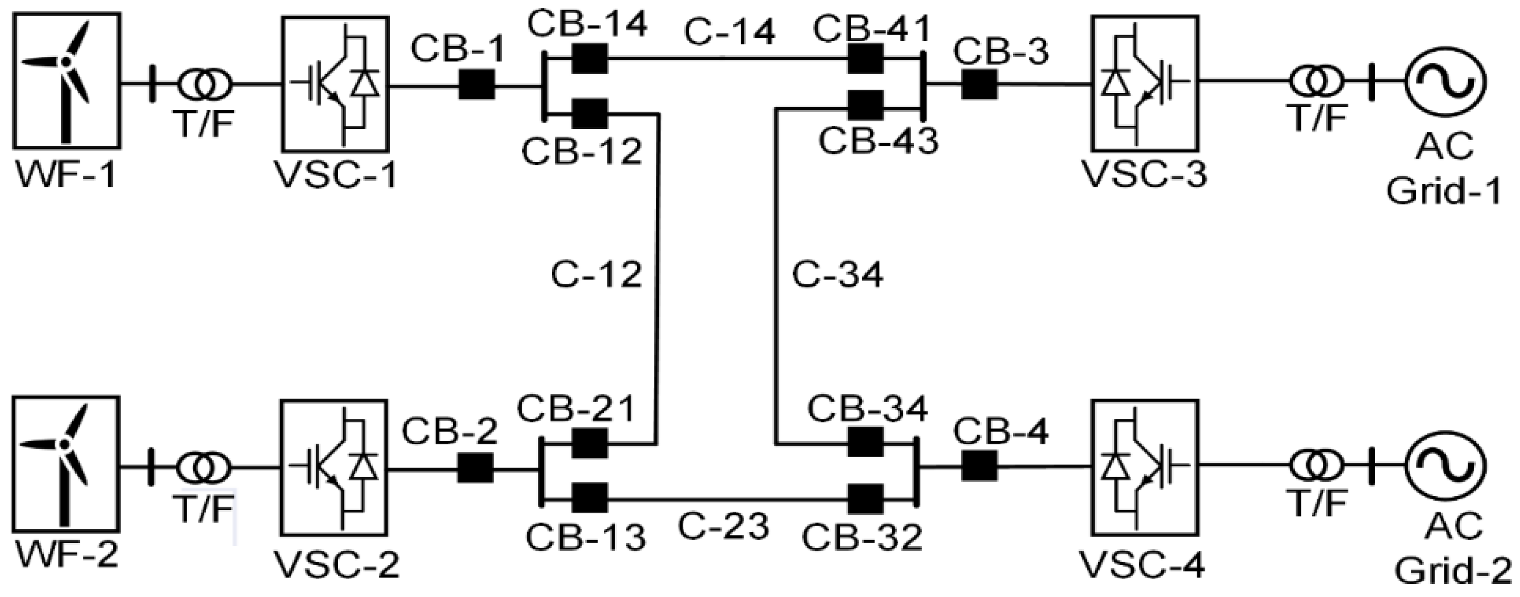
2. M-HVDC Test System Model

A single-line diagram of the proposed VSC-based four-terminal HVDC grid test system is shown in Figure 1. The proposed test system consists of a symmetrical bipolar transmission line configuration, considering positive and negative DC voltages. H-DCCBs are connected at each end of the transmission line for protection against DC faults. A total of 12 H-DCCBs are utilized in the test system. In addition, a series reactor (100 mH) is connected with each H-DCCB to limit the rate of rising of the DC fault current. Lengths for the DC cables C14, C12, C34, and C23 are 300 km, 100 km, 100 km, and 300 km, respectively. The grid test system utilizes a ±400 kV HVDC link. The operational parameters for the M-HVDC grid system are listed in Table 1.
All VSCs are modeled using half-bridge multi-modular converters (MMCs) [33]. P-Vac control is employed on offshore converter stations (VSC-1 and VSC-2) to maintain constant active power throughout the M-HVDC grid. This control also provides AC voltage regulation at the point of common coupling (PCC) [1]. Lastly, P-Vdc droop control and reactive power control settings are implemented on the onshore converter stations (VSC-3 and VSC-4) [34]. This control mode ensures constant DC link voltages and regulates the reactive power exchange between converters and AC grids.
The bidirectional H-DCCB parameters and their component ratings are listed in Table 2. 5SNA 2000K450300 IGBT module is chosen for load commutation switch (LCS) and main breaker (MB). The LCS comprises a 3 × 3 IGBT module configuration, whereas MB consists of 200 connected IGBT modules divided into four stacks.

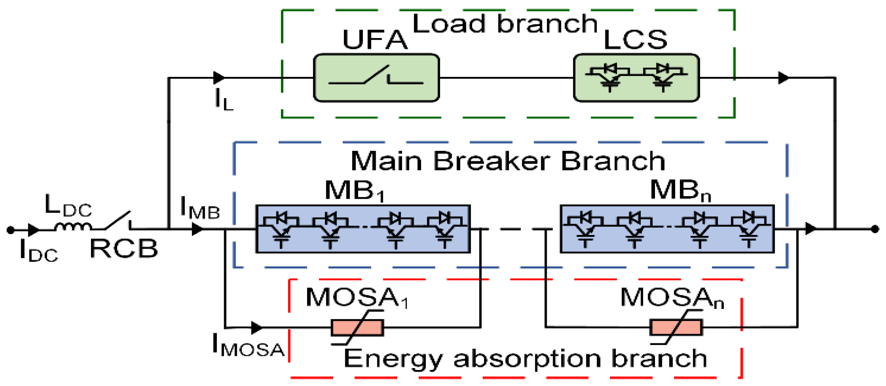
3. H-DCCB Proposed by the ABB

The schematic of H-DCCB as proposed by ABB is illustrated in Figure 2 [15]. This general topology comprises three parallel branches: the load branch, the main breaker (MB) branch, and the energy absorption branch. A slow mechanical switch in the form of a residual circuit breaker (RCB) is inserted in the series before the main assembly of the hybrid breaker. The load branch consists of an ultra-fast mechanical actuator (UFA), in series with an IGBT-based load commutation switch (LCS). In contrast, the main breaker branch comprises sections of series and parallel combinations of IGBT valves.
The metal oxide surge arrestors (MOSA) in this H-DCCB are dedicated to absorbing the magnetic energy stored in the system inductances. Multiple MOSA blocks are stacked in the energy absorption branch in parallel with the IGBT valves of MB, ensuring equal current distribution and efficient energy handling capability. In addition, MOSAs limit transient interruption voltages (TIV) during the current interruption process [35].
The use of semiconductor switches in H-DCCB offers the required high operation speed in the range of a few milliseconds. Additionally, on-state losses are significantly reduced because the current does not pass through the IGBT valves of MB unless a fault occurs.
Initially, under normal conditions, the IGBT valves of LCS in an H-DCCB are in a closed state while MB is in an open state. Hence, during normal load conditions, the DC load current passes through the load branch only. The corresponding current waveform of H-DCCB, as proposed by ABB, is shown in Figure 3 [15]. The general strategy for DC fault isolation using an H-DCCB consists of the following sequence of events [36]:
Step 1: During normal operating conditions, the IGBT valves of LCS are closed while IGBT valves of MB are opened. Due to the low impedance of the load branch, most of the load current passes through it, as shown in Figure 4a.
Step 2: At time t1, a short circuit fault occurs, and the DC fault current rises rapidly at the DC side of the VSC. As the DC fault current reaches a set threshold (trip-value), a trip signal is issued at t2. LCS is immediately opened, and the IGBT valve of the MB branch is turned ON, causing the fault current to commutate to the MB from the load branch. This procedure is generally referred to as the first commutation process, as shown in Figure 4b. This process triggers the opening of UFA as well.
Step 3: The contacts of UFA are fully separated within 2 ms [15], such that they can withstand and protect the LCS from transient interruption voltages. The IGBT valves in MB are then turned off at time t3.
Step 4: The above action causes the DC fault current to commutate into the energy dissipation branch. Eventually, this DC fault current is dissipated through the counter voltages of the MOSA from time t3 to t4, as illustrated in Figure 4c.
Step 5: Most of the fault current is interrupted at this stage, and only a small leakage current pass through the MOSA. Finally, to prevent arrestors from thermal overload, the RCB is opened at t4, as shown in Figure 4d.

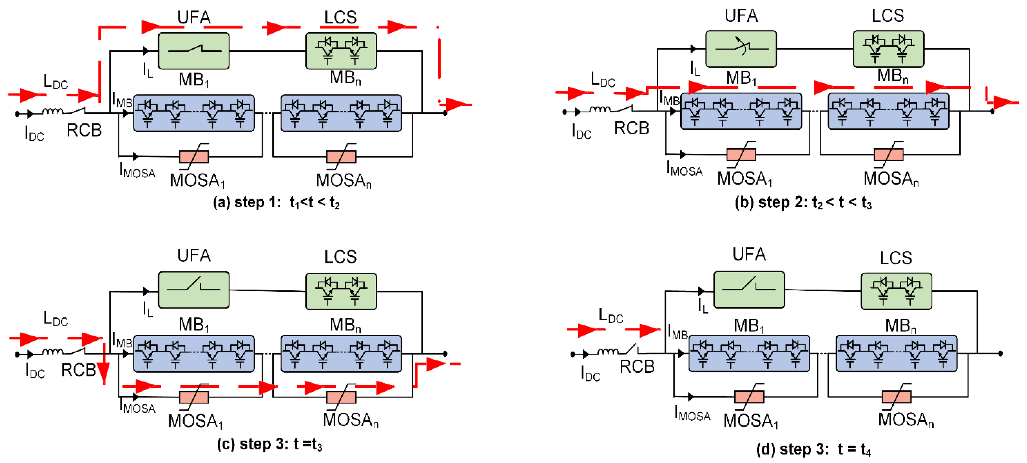
4. H-DCCB Protection Flow Chart

There are three primary levels of protection from which a trip signal can be issued to an ABB H-DCCB: grid-level protection, self-level protection, and driver-level protection, as illustrated in Figure 5 [37].
In grid-level protection, the H-DCCB breaker initiates the tripping sequence on receiving the trip order from the M-HVDC grid protection system. However, in self-level protection, the H-DCCB starts the tripping sequence by itself. A self-level protection scheme is implemented if the grid-level protection fails to issue a trip command or if the temperature of the IGBT valve exceeds a certain threshold. In doing so, the breaker components are prevented from incurring any damage. Lastly, a driver-level protection scheme is also embedded in the IGBT valves of the load and MB branches. This protection scheme is activated once the DC fault current reaches the rated current of the IGBT valves, leading to the permanent destruction of the IGBT valves of LCS and the MB [38].

5. Stress Analysis during DC Fault

An H-DCCB must withstand the peak DC fault current and the TIV imposed by surge arrestors to successfully interrupt a DC fault current. This exposes the IGBT valves to current, voltage, energy absorption, and thermal stresses.
IGBT valves are the most sensitive and expensive component in an H-DCCB. Also, as the system rating increases, the cost for the IGBT valves increases proportionally. Therefore, studying the various critical stresses that the IGBT valves are exposed to during service conditions is essential.

5.1. Voltage and Current Stresses

H-DCCB needs to withstand a voltage level more than the system voltage during a DC fault to reduce the fault current magnitude equal to or lesser than that of the residual current value in a short duration of time [3]. The IGBTs are connected in parallel with the surge arrestors in the main branch. Therefore, the maximum voltage stress that the IGBT valves are being subjected to is directly dependent on the clipping voltage level of these surge arrestors [39]. Generally, surge arrestors’ clipping voltage should be below the voltage rating of the IGBT valves to prevent them from any overvoltage damage during the DC faults [40]. However, the IGBT valves must withstand up to 1.5 times the rated system voltage during the internal current commutation process [39]. The voltage stresses on each IGBT in MB can also be reduced through their appropriate paralleling and series interconnections [41]. Finally, once the fault is cleared, the breaker components are subjected to system-level voltages.
During fault current interruption, the IGBT valves of the LCS are subjected to voltage stress equal to the voltage drop across the MB branch, which is given by (1):
V LCS = N s V ce ( on ) + N s R on I f ( max )
The on-state voltage (Vce(on)), as well as the on-state resistance (Ron) for each IGBT module, are assumed to be 2.6 V and 1.44 mΩ, while the maximum breaking current (If(max)) is 11.5 kA, respectively. Using (1), the voltage stress applied to the LCS valves is found to be 3.83 kV. Considering the individual module voltage rating of 4.5 kV, this voltage stress on the LCS valves is well below its rated voltage [42]. However, practically a 3 × 3 configuration of IGBT modules is used in LCS to provide adequate voltage and minimal power loss.
DC faults cause over-current stresses in IGBT modules. This occurs when current levels reach several times higher than the rated current carrying capacity of the IGBT module. This leads to accelerated aging of the module, as well as decreasing its lifetime and reliability. De-saturation of the IGBT valve may also occur during a DC fault, causing high conduction losses and severe overheating, leading to valve destruction [43].
Using a series current limiting reactor ensures that the fault current magnitude does not exceed the current rating of the components of H-DCCB. Assuming a 10% system over-voltage, the appropriate value of the current limiting reactor (LR) is dependent on the rated system voltage (VDC) as well as the rate of rising of the DC fault current (di/dt) [21]. Hence, the value of the DC limiting reactor is determined as:
L R = 1.1 V DC ( di / dt )
Furthermore, the rate of the DC fault current is also influenced by various factors; the distance between the fault and the circuit breaker, the number of feeders connected to the closest bus and the breaker, and the type of DC transmission used within the M-HVDC grid [44].

5.2. MOSA Energy Absorption Stress

Apart from handling the voltage stress due to TIV, the other leading role of MOSA in an H-DCCB is to bear the energy absorption stress during the current extinguishing process. Therefore, individual MOSA stacks may be arranged in parallel columns across each IGBT module. This ensures efficient energy absorption capacity and provides a greater degree of redundancy [35].
During the energy absorption stage, the rate at which the fault current decay is determined by the current limiting reactor and the clamping voltage of the MOSA (VMOSA) across the breaker as given by (3) to (5) [25]:
V DC = 1 1.10 ( V R + V CB )
In (3), VR represents the voltage across the reactor induced during the DC fault. Additionally, VCB is the voltage across the breaker terminals before the current is commutated to the energy absorption branch, i.e., the first commutation process.
Once the DC fault current commutates to the energy absorption branch, the breaker terminal voltage is limited by the clamping voltage of the MOSA, VMOSA. The line voltage VDC at this interruption state is expressed in (4).
V DC = 1 1.10 [ di dt ( L R ) + V MOSA ]
di dt = 1.10 ( V DC ) L R V MOSA
TMOSA is the time required by H-DCCB to suppress the maximum DC fault current (If(max)) to zero and is determined by (6). This time depends on factors like the clamping voltage of the MOSA, system voltage rating, the current limiting reactor (LR) value, and resistance between the fault and breaker (Rl).
T MOSA = L R R F ln [ 1 + R l V MOSA V DC I f ( max ) ]
Therefore, the total energy dissipated, EMOSA, by the arrestors during its conduction time is represented by (7) [21]:
E MOSA = 0 T MOSA ( V MOSA I MOSA ) dt
It can be deduced from the (6) and (7) that decreasing the voltage rating of MOSA will increase its energy absorption capability. However, this leads to a longer current supersession time [45]. Therefore, the rated energy dissipation value of the arrestor must be higher than EMOSA.
Hence in an H-DCCB connected within the M-HVDC grid, the voltage rating of the MOSA can be made higher, well within the withstanding capability of the IGBT valves. This results in rapid fault current suppression, ultimately reducing the energy stresses on the MOSA [46].

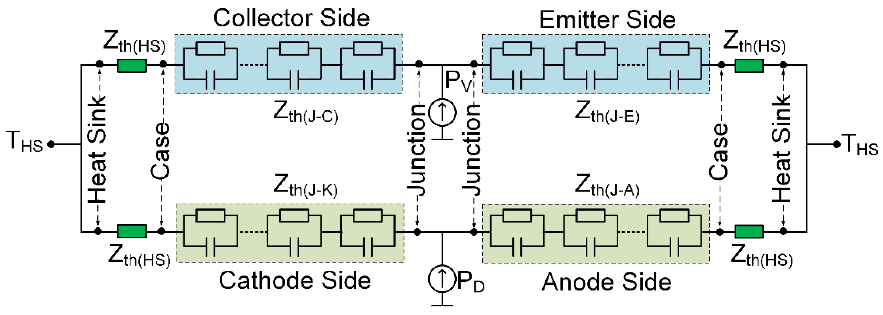
5.3. Thermal Stresses on Press-Pack IGBT Module

In an H-DCCB, LCS is responsible for conducting current during normal load conditions and conducting a low magnitude short duration fault current just at the instance of fault inception before it is eventually opened. Therefore, it is incorporated with a water-cooling system in this study. In contrast, the MB only conducts a high magnitude fault current for a time interval equal to the opening time of the UFA, which is around 2 ms [15]. Hence, an air-cooling system is used for heat dissipation in the MB valves during this period. This results in a difference in the junction temperature for the IGBT modules located in the LCS and UFA.
For a modern VSC-HVDC system, press-pack IGBT technology is more attractive than conventional IGBT module technology due to various advantages, as presented in [42]. Therefore, this technology is used in this study. The thermal model of a single press-pack IGBT module with a double-sided cooling system is used in H-DCCB, as shown in Figure 6. The power dissipated through the IGBT valves, and the corresponding free-wheeling diode is represented as PV and PD, respectively. The IGBT chip thermal impedances between junction to collector and junction to emitter surfaces are defined as Zth(J-C) and Zth(J-E), respectively. In contrast, Zth(J-K) and Zth(J-A) are the thermal impedances between junction to cathode and junction to anode surface of diode. Zth(HS) is the thermal impedance between the module case (body) and the heat sink. This is the same for both IGBT and diode sides [42]. The junction and case (body) temperature at each emitter and collector side is denoted as TV-J. In contrast, TD-J is the junction and module case temperature between the cathode and the anode side of the diode. Lastly, THS represents the heat sink temperature of the press-pack IGBT module.
For the sake of simplicity, it is assumed that all the thermal impedances between the junction and case for both the IGBT chip and diode are represented as Zth(V-JC) and Zth(D-JC). The typical values of the Zth(V-JC) and Zth(D-JC) are 4 mK/W, whereas Zth(V-CH) and Zth(D-CH) are 0.001 K/W [42].
During a typical current interruption scenario, the switching losses of IGBT valves in MB and LCS can be ignored, and only the conduction losses are considered. Assuming that the entire fault current passes through the IGBT valve, the average conduction losses, PL can be determined using (8):
P L = V ce ( on ) I avg + R on I avg 2
In (8), Vce(on) is IGBT on-state voltage, Iavg is the average current passing through LCS, and Ron is the on-state resistance of the IGBT module. Under normal conditions, the average load current passing through the H-DCCB when connected in a four-terminal HVDC test system is 1.8 kA. Additionally, Ron and Vce(on) are approximately 1.44 mΩ and 2.6 V, respectively [42]. As it is supposed that LCS is composed of a 3 × 3 IGBT matrix, and considering equal load sharing among each IGBT valve, the average load current is passing through each IGBT unit branch, Iavg is 0.60 kA. The average power loss of individual IGBT valves in LCS is thus determined to be approximately 2 kW.
The IGBT valves of the LCS are forcibly cooled and kept at 36 °C. Therefore, the heatsink temperature is assumed to be always 36 °C. From (9), the junction temperature is found to be around 46 °C. Indeed, the junction temperature of the IGBT module is well below its maximum temperature limit of 125 °C [42].
T J = P L ( Z th ( V - JC ) + Z th ( V - CH ) + ) T HS
Suppose that, during a DC fault, the heat generated due to the conduction losses in the IGBT module is not continuously dissipated due to variation in the heatsink temperature. In that case, the IGBT module temperature may rise above the rated value. This increases the thermal resistance of the IGBT chip in the module and decreases valve conductivity [47].

6. Results and Discussion

As illustrated in Figure 1, a four-terminal test system is developed in PSCAD/EMTDC to study and evaluate the electrical and thermal stresses on the IGBT valves and energy absorbed by the surge arrestors within H-DCCB during different DC fault current scenarios. H-DCCB, as proposed by ABB, is used in the simulation study. Current limiting reactors are added in a series of H-DCCB to limit the DC fault current for effective H-DCCB operation [41]. Employed parameters of the four-terminal test system and H-DCCB are enlisted in Table 1 and Table 2, respectively.
The developed test system is assessed/tested for two types of protection levels: grid-level and self-level protections to evaluate the electrical and thermal stresses imposed on the H-DCCB by the M-HVDC grid system. The study of stresses associated with driver-level protection is intended to be carried out in the future.

6.1. Grid-Level Protection

Under normal operating conditions, a trip signal to hybrid breaker is provided externally through a dedicated HVDC protection system [1]. The protection system monitors various M-HVDC grid parameters and issues a trip command to H-DCCB in case of any fault occurrence. H-DCCB initiates the tripping sequence on receiving the external trip sequence from the M-HVDC protection system.

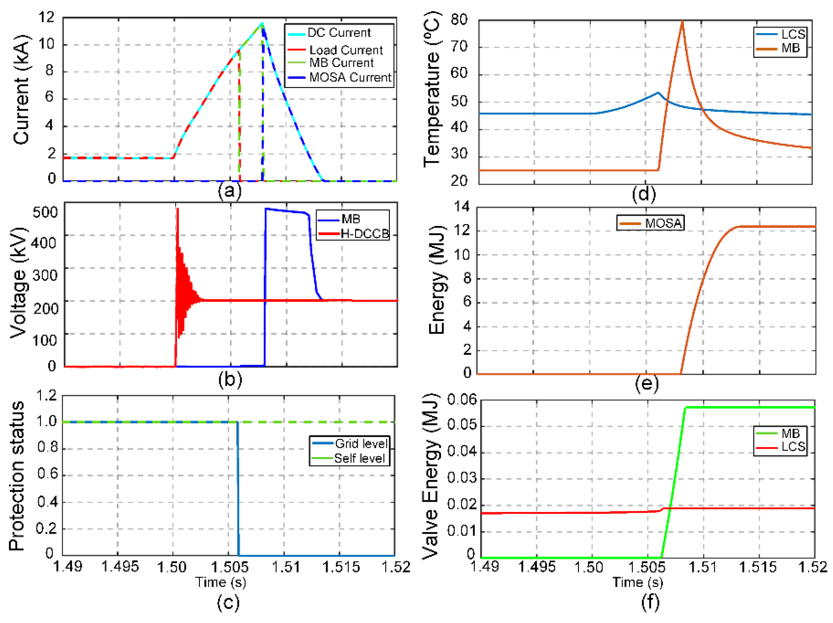
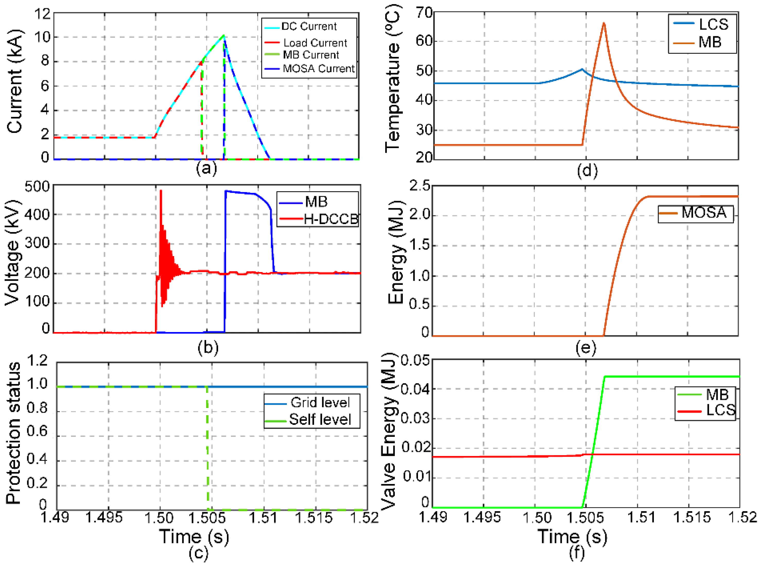
6.1.1. Low Impedance Fault Current Interruption

Simulation results of H-DCCB on receiving the trip signal from the grid-level protection scheme are shown in Figure 7. At t = 1.5 s, a low impedance fault is applied at VSC- 4, causing a high DC fault current to flow. The DC grid-level protection scheme issues a trip command with a delay of 6 ms to ensure that the DC fault current reaches the rated breaker current of 11.5 kA. The fault current, in this case, is well beyond the 9 kA, which is the interruption capability for H-DCCB as proposed by ABB [15]. Thus, by delaying the grid signal, maximum electrical and thermal stresses within the breaker rated limits can be exerted on the breaker components to visualize the effects of practical grid delays in the DC grid.
However, practically, the trip command is issued much sooner to extinguish the fault current safely well below the rated value of the breaker, 11.5 kA in this study. Additionally, the self-level protection of the H-DCCB is disabled as it may issue a trip command below 90% of the rated current value of the breaker.
The respective currents flowing through the load, MB, and energy absorption branches of the H-DCCB are shown in Figure 7a. It should be noted that the commutation of the fault current from the LCS to MB branch occurs when grid trip signal is zero, as well as when the LCS is opened. Afterward, the MB is only opened after the UFA is fully opened. The fault current then commutates to the MOSA branch before being extinguished. The IGBT valves of MB must bear greater current stress than the LCS valves as they are responsible for conducting the peak fault current.
The IGBT junction temperature for both LCS and MB is shown in Figure 7d. It is assumed that the LCS valves are water-cooled at 40 °C. In contrast, the MB valves are air-cooled as they are only responsible for conducting the transient fault current for a short time, around 2 ms only. The ambient air temperature is set to 20 °C for MB valves in this study. The pre-fault temperature of the LCS valve is seen to be only 10 °C greater than the coolant temperature, due to the 3 × 3 configuration of the IGBT valves in the LCS. This divides the current in each branch equally, leading to a small power loss in individual IGBT valves. The LCS valve temperature increases to just 53 °C, compared to a sharp rise in the MB valve temperature to around 80 °C. Still, the MB valve temperature does not exceed its maximum temperature limit of 125 °C [42].
The energy dissipated across the LCS, and MB valves is shown in Figure 7e. It can be observed that the thermal stress in terms of energy dissipation across the IGBT valve of MB is comparatively greater than that of LCS. This is because the MB valves are responsible for handling the peak fault current for a short time before transferring to the MOSA branch. However, it is evident from Figure 7f that the MOSA branch is primarily responsible for neutralizing the fault current, as a large amount of energy is dissipated through this branch, around 12.4 MJ.

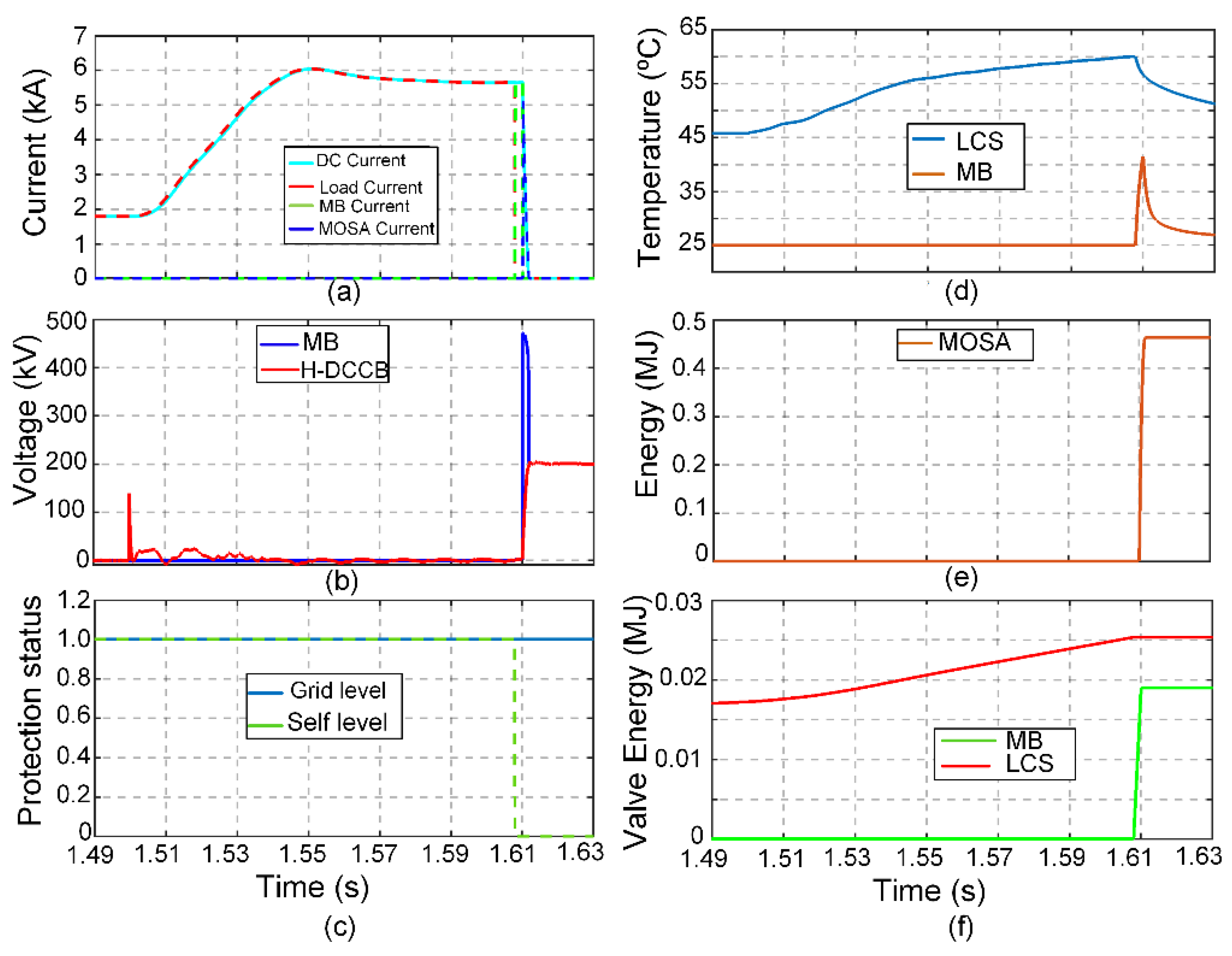
6.1.2. High Impedance Fault Current Interruption

A high impedance fault causes a relatively lower fault current than the rated current of the H-DCCB, 11.5 kA. Self-level protection of the breaker is disabled to observe the thermal stresses on the IGBT valves. A high impedance fault occurs at t = 1.5 s, and the tripping threshold is set to 4 kA. The corresponding current waveforms are shown in Figure 8a. Both electrical and thermal stresses on the breaker components are reduced due to a decrease in the fault current magnitude. The maximum current passing through the LCS is around 4 kA, whereas the MB valves face up to 5.55 kA current. Due to a decreasing fault current magnitude, both LCS and MB valves undergo reduced thermal stresses, as shown in Figure 8d. A slight temperature variation in the LCS valve is observed, whereas the temperature of the MB valves reaches a peak of around 39 °C. Additionally, the energy dissipation of the LCS valve is almost 17 kJ, which is slightly greater than that of the MB valves. However, the IGBT valve energy dissipation value is negligible compared to the 2.58 MJ of energy dissipation through MOSAs, as shown in Figure 8.

6.2. Self-Level Protection

HVDC grid protection methods may rely on local measurements and information from both ends of the DC line. Various DC grid protection strategies are in practice, such as over-current and under-voltage protection [48], the ratio of transient voltage (ROTV) at the converter and line side [49,50], as well as the rate of change of voltage (ROCV) across the current limiting inductor [45]. Still, no matter how advanced and reliable a grid protection strategy is, there is always a chance of failure.
Therefore, in future M-HVDC grids, breaker testing must be done for grid-level protection failure. In such a scenario, the H-DCCB may be exposed to high DC fault currents without any trip signal being initiated from the grid protection system. Therefore, if the self-level protection of the H-DCCB is not activated in a timely fashion, it ultimately leads to thermal breakdown and destruction of the M-HVDC.

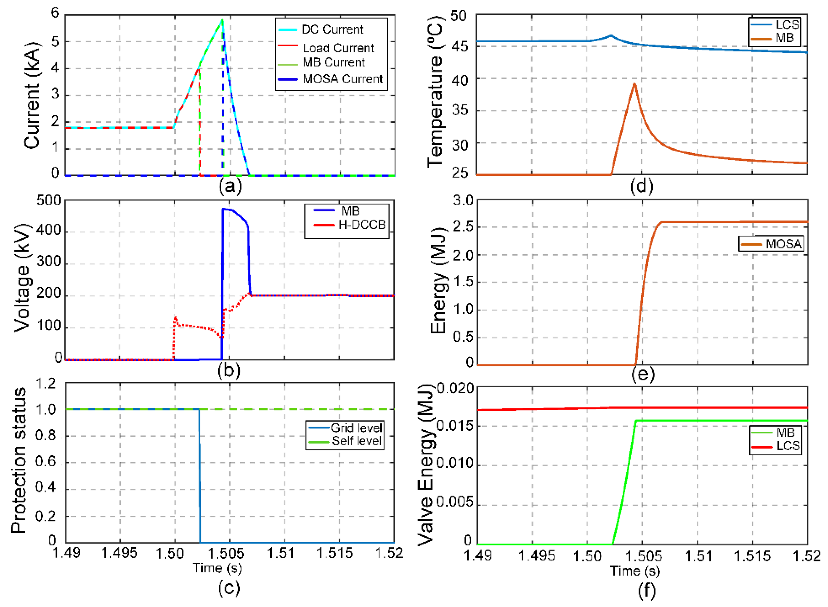
6.2.1. Low Impedance Fault Current Interruption

Simulation results for low impedance fault current under self-protection are shown in Figure 9. Grid-level protection is disabled (Grid Order = 1) as shown in Figure 9c. At t = 1.5 s, a low impedance high current fault is induced. The self-protection system of the H-DCCB monitors the load current and initiates the self-level protection (SP Order = 1) at t = 1.504 s as seen in Figure 9c. This causes LCS to operate such that the peak fault current can only reach 90% of its rated interrupting current, that is 10.3 kA as shown in Figure 9a. The duration of voltage stress appearing on the IGBT valves and MOSAs in case of low impedance fault under self-protection is greater as compared to fault interruption under grid level protection as shown in Figure 9b.
The temperature of the IGBT valves is illustrated in Figure 9d. LCS and MB valves attain a peak temperature of 50.5 °C and 66 °C, respectively. Like the low impedance fault under grid-level protection, the IGBT valves of MB, in this case, attain a higher temperature than the LCS valves. However, as the self-level protection system of the DCCB opens the LCS at 8 kA, the corresponding temperature peaks of LCS and MB are lower in self-level protection scenario than in the case of grid-level protection. In addition, the energy absorbed by the MOSAs is 2.25 MJ, as shown in Figure 9e. The combined energy dissipated by IGBT valves is far less than the energy dissipated by the surge arrestors as shown in Figure 9f. This is because only a small number of IGBT valves are used in LCS as well as turning-on of the MB valves at the time of commutation of current only.

6.2.2. High Impedance Fault Current Interruption

In a high impedance fault, the fault current is lower than the rated interrupting threshold current of the breaker. The thermal management system incorporated in LCS monitors IGBT valve temperature. In this case, a trip command is issued if the temperature exceeds a pre-defined threshold of 60 °C as illustrated is Figure 10c.
At =1.5 s, a high impedance fault is applied, and the corresponding current waveforms are shown in Figure 10a. As expected, it is observed that the fault current magnitude is lesser than the rated interrupting current, at 11.5 kA. However, in contrast to the high impedance fault under grid-level control, the trip command is delayed until the LCS valves reach a threshold temperature of 60 °C as seen in Figure 10d. This causes a considerable delay before the LCS can be opened. The LCS opens when the self-level protection is activated (SP = 0), and the fault current commutes to the MB. This causes a momentary rise in MB valve temperature, and it rises to 42 °C only, as shown in Figure 10d.
Once the UFA has fully opened, the MB turns off, and the fault current is finally neutralized in the energy absorption branch by dissipating 0.46 MJ energy only as seen in Figure 10e. It is also seen from Figure 10f that the energy dissipated through the LCS valve is higher than the MB valve due to the delayed operation of the H-DCCB. However, this energy dissipation stress is still significantly lower than the MOSA energy. Lastly, the duration of the voltage stress due to the TIV imposed by the MOSA branch is the smallest in this case as shown in Figure 10b.
By assessing the stresses imposed on H-DCCB as proposed by ABB in the M-HVDC system, it can be concluded that the ABB H-DCCB can reliably be used in future M-HVDC grids.

7. Conclusions

In this paper, the impacts of the M-HVDC grid on the operational parameters of the hybrid HVDC circuit breakers are assessed. Simulations were developed for a four-terminal HVDC system in PSCAD/MTDC with 12 H-DCCBs. A range of DC fault scenarios were presented, and operational parameters were evaluated, e.g., electrical, and thermal stresses on the IGBT valves of H-DCCB. From rigorous simulations, it was concluded that the worst fault scenario is the low impedance fault under the grid-level protection scheme. However, under a self-protection scheme, the IGBT valves undergo maximum thermal stress for a comparatively long duration during a high impedance fault current interruption. Therefore, the cooling mechanism of the IGBT valves in LCS must not fail, especially under this type of fault. Lastly, the IGBT valves of MB experience prolonged voltage stress due to TIV imposed by the MOSA branch under low impedance fault scenarios compared to high impedance faults.

Author Contributions

Conceptualization, A.R. and S.K.; methodology, A.R. and S.K.; formal analysis, A.R., S.K., U.A., G.A. and M.J.; investigation, U.A., M.Z.Y. and N.S.; resources, U.A. and N.S.; data curation, A.R., S.K., M.Z.Y., M.J. and G.A.; writing—original draft preparation, A.R., S.K. and G.A.; writing—review and editing, U.A., M.Z.Y., G.A., M.J. and N.S.; funding acquisition, U.A. and N.S. All authors have read and agreed to the published version of the manuscript.

Funding

This research received no external funding.

Institutional Review Board Statement

Not applicable.

Informed Consent Statement

Not applicable.

Data Availability Statement

Not applicable.

Conflicts of Interest

The authors declare no conflict of interest.

References

  1. Raza, A.; Akhtar, A.; Jamil, M.; Abbas, G.; Gilani, S.O.; Yuchao, L.; Khan, M.N.; Izhar, T.; Dianguo, X.; Williams, B.W.; et al. A Protection Scheme for Multi-Terminal VSC-HVDC Transmission Systems. IEEE Access 2018, 6, 3159–3166. [Google Scholar] [CrossRef]
  2. Muniappan, M. A comprehensive review of DC fault protection methods in HVDC transmission systems. Prot. Control Mod. Power Syst. 2021, 6, 1–20. [Google Scholar] [CrossRef]
  3. Barnes, M.; Vilchis-Rodriguez, D.S.; Pei, X.; Shuttleworth, R.; Cwikowski, O.; Smith, A.C. HVDC Circuit Breakers—A Review. IEEE Access 2020, 8, 211829–211848. [Google Scholar] [CrossRef]
  4. Liu, Y.; Jin, Y.; Li, Z.; Liu, Y.; Li, B.; Duan, Z. Mechanical DC Breakers and Hybrid MMC Based Coordinated Strategy for MMC-HVDC DC Fault Riding Through. IEEE J. Emerg. Sel. Top. Power Electron. 2021. [Google Scholar] [CrossRef]
  5. Liu, F.; Liu, W.; Zha, X.; Yang, H.; Feng, K. Solid-State Circuit Breaker Snubber Design for Transient Overvoltage Suppression at Bus Fault Interruption in Low-Voltage DC Microgrid. IEEE Trans. Power Electron. 2017, 32, 3007–3021. [Google Scholar] [CrossRef]
  6. Stumpe, M.; Tünnerhoff, P.; Dave, J.; Schnettler, A.; Ergin, D.; Schoen, A.; Würflinger, K.; Schettler, F. DC fault protection for modular multi-level converter-based HVDC multi-terminal systems with solid-state circuit breakers. IET Gener. Trans. Distrib. 2018, 12, 3013–3020. [Google Scholar] [CrossRef]
  7. Ludin, G.A.; Amin, M.A.; Matayoshi, H.; Rangarajan, S.S.; Hemeida, A.M.; Takahashi, H.; Senjyu, T. Solid-State DC Circuit Breakers and Their Comparison in Modular Multilevel Converter Based-HVDC Transmission System. Electronics 2021, 10, 1204. [Google Scholar] [CrossRef]
  8. Hafner, J.; Jacobson, B. Proactive hybrid HVDC breakers—A key innovation for reliable HVDC grid. In Proceedings of the Electric Power System of the Future-Integrating Supergrids and Microgrids, Cigre Symposium, Bologna, Italy, 13–15 September 2011; pp. 264–272. [Google Scholar]
  9. Zhou, W.; Wei, X.; Zhang, S.; Tang, G.; He, Z.; Zheng, J.; Dan, Y.; Gao, C. Development and test of a 200kV full-bridge based hybrid HVDC breaker. In Proceedings of the 17th European Conference on Power Electronics and Applications (EPE’15 ECCE-Europe), Geneva, Switzerland, 8–10 September 2015; pp. 1–7. [Google Scholar]
  10. Bösche, D.; Wilkening, E.; Köpf, H.; Kurrat, M. Hybrid DC Circuit Breaker Feasibility Study. IEEE Trans. Compon. Packag. Manuf. Technol. 2017, 7, 354–362. [Google Scholar] [CrossRef]
  11. Rao, H.; Zhou, Y.; Zou, C.; Xu, S.; Li, Y.; Yang, L.; Huang, W. Design aspects of hybrid HVDC system. CSEE J. Power Energy Syst. 2021, 7, 644–653. [Google Scholar]
  12. Abedrabbo, M.; Leterme, W.; Hertem, D.V. Impact of operational parameters on HVDC circuit breaker requirements. In Proceedings of the CIGRE-IEC 2019 Conference on EHV and UHV (AC & DC), Hakodate, Japan, 23–26 April 2019; p. 9. [Google Scholar]
  13. Raza, A.; Mustafa, A.; Alqasemi, U.; Rouzbehi, K.; Muzzammel, R.; Guobing, S.; Abbas, G. HVdc Circuit Breakers: Prospects and Challenges. Appl. Sci. 2021, 11, 5047. [Google Scholar] [CrossRef]
  14. Xiao, H.; Xu, Z.; Xiao, L.; Gan, C.; Xu, F.; Dai, L. Components Sharing Based Integrated HVDC Circuit Breaker for Meshed HVDC Grids. IEEE Trans. Power Deliv. 2020, 35, 1856–1866. [Google Scholar] [CrossRef]
  15. Callavik, M.; Blomberg, A.; Hafner, J.; Jacobson, B. Break-through! ABB’s hybrid HVDC breaker, an innovation breakthrough enabling reliable HVDC grids. Abb. Rev. 2012, 2, 7–13. [Google Scholar]
  16. Grieshaber, W.; Dupraz, J.-P.; Panache, D.-L.; Violleau, L. Development and test of a 120 kV direct current circuit breaker. CIGRE Paris 2014, 1–11, Paper B4–301. [Google Scholar]
  17. Zheng, X.; Jia, R.; Gong, L.; Zhang, G.; Pei, X. An optimized coordination strategy between line main protection and hybrid dc breaker for VSC-based dc grid using overhead transmission line. Energies 2002, 12, 1462. [Google Scholar] [CrossRef] [Green Version]
  18. An, T.; Tang, G.; Wang, W. Research and application on multi-terminal and DC grids based on VSC-HVDC technology in China. High Volt. 2017, 2, 1–10. [Google Scholar] [CrossRef]
  19. Smeets, R. Safeguarding the Supergrid. IEEE Spectr. 2015, 52, 38–43. [Google Scholar] [CrossRef]
  20. Shukla, A.; Demetriades, G.D. A Survey on Hybrid Circuit-Breaker Topologies. IEEE Trans. Power Deliv. 2014, 30, 627–641. [Google Scholar] [CrossRef]
  21. Belda, N.A.; Smeets, R.P.P. Test Circuits for HVDC Circuit Breakers. IEEE Trans. Power Deliv. 2016, 32, 285–293. [Google Scholar] [CrossRef]
  22. Tokuyama, S.; Arimatsu, K.; Yoshioka, Y.; Kato, Y.; Hirata, K. Development and Interrupting Tests on 250KV 8KA HVDC Circuit Breaker. IEEE Trans. Power Appar. Syst. 1985, 104, 2452–2459. [Google Scholar] [CrossRef]
  23. Tamura, S.; Shimada, R.; Kito, Y.; Kanai, Y.; Koike, H.; Ikeda, H.; Yanabu, S. Parallel Interruption of Heavy Direct Current by Vacuum Circuit Breakers. IEEE Trans. Power Appar. Syst. 1980, 3, 1119–1129. [Google Scholar] [CrossRef]
  24. Belda, N.A.; Plet, C.A.; Smeets, R.P.P. Full-Power Test of HVDC Circuit-Breakers with AC Short-Circuit Generators Operated at Low Power Frequency. IEEE Trans. Power Deliv. 2019, 34, 1843–1852. [Google Scholar] [CrossRef]
  25. Gao, C.; Ding, X.; Tang, G.; Wang, G.; Qiu, P. Key stress extraction and equivalent test method for hybrid DC circuit breaker. Glob. Energy Interconnect. 2018, 1, 29–38. [Google Scholar]
  26. Xu, Z.; Xiao, H.; Xu, Y. Two basic ways to realize DC circuit breakers. J. Eng. 2019, 2019, 3098–3105. [Google Scholar] [CrossRef]
  27. Hofmann, G.; LaBarbera, G.; Reed, N.; Shillong, L.; Long, W.; Melvold, D. Field test of HVDC circuit breaker: Load break and fault clearing on the Pacific intertie. IEEE Trans. Power Appar. Syst. 1976, 95, 829–838. [Google Scholar] [CrossRef]
  28. Melvold, D.; Shockley, P.; Long, W.; Hingorani, N. Three terminal operations of the Pacific HVDC intertie for dc circuit breaker testing. IEEE Trans. Power Appar. Syst. 1976, 95, 1287–1296. [Google Scholar] [CrossRef]
  29. Yanabu, S.; Tamagawa, T.; Irokawa, S.; Horiuchi, T.; Tomimuro, S. Development of HVDC Circuit Breaker and its Interrupting Test. IEEE Trans. Power Appar. Syst. 1982, 101, 1958–1965. [Google Scholar] [CrossRef]
  30. Shimada, R.; Tani, K.; Kishimoto, H.; Tamura, S.; Ikeda, H.; Tamagawa, T.; Yanabu, S.; Matsushita, T. Synthetic test methods of high-direct-current circuit breaker. Proc. Inst. Electr. Eng. 1979, 126, 965–970. [Google Scholar] [CrossRef]
  31. Sheng, B. A synthetic test circuit for current switching tests of HVDC circuit breakers. In Proceedings of the IEEE/PES Transmission and Distribution Conference and Exposition, Chicago, IL, USA, 21–24 April 2008. [Google Scholar]
  32. Du, C.; Wang, C. Review of DC Circuit Breaker Technology for HVDC Application. In Proceedings of the 22nd International Conference on Electrical Machines and Systems (ICEMS), Harbin, China, 11–14 August 2019; pp. 1–6. [Google Scholar]
  33. Leterme, W.; Ahmed, N.; Beerten, J.; Ängquist, L.; Hertem, D.V.; Norrga, S. A new HVDC grid test system for HVDC grid dynamics and protection studies in EMT-type software. In Proceedings of the 11th IET International Conference on AC and DC Power Transmission, Birmingham, UK, 10–12 February 2015. [Google Scholar]
  34. Raza, A.; Dianguo, X.; Yuchao, L.; Xunwen, S.; Williams, B.W.; Cecati, C. Coordinated Operation and Control of VSC Based Multiterminal High Voltage DC Transmission Systems. IEEE Trans. Sustain. Energy 2016, 7, 364–373. [Google Scholar] [CrossRef] [Green Version]
  35. Hock, P.; Belda, N.; Hinrichsen, V.; Smeets, R. Investigations on Metal-Oxide Surge Arresters for HVDC Circuit Breaker Applications. In Proceedings of the INMR World Congress, Tucson, AZ, USA, 20–23 October 2019. [Google Scholar]
  36. Hesami, M.; Bakhshi, A.; Mousavi, S.; Rouzbehi, K.; Escaño, J.M. HVDC Breaker Power Loss Reduction by Bridge-Type Hybrid Breakers. Energies 2021, 14, 1526. [Google Scholar] [CrossRef]
  37. Lin, W.; Jovcic, D.; Nguefeu, S.; Saad, H. Modelling of high-power hybrid DC circuit breaker for grid-level studies. IET J. Power Electron. 2016, 9, 237–246. [Google Scholar] [CrossRef]
  38. Promotion EU Project. WP6, Deliverable 6.3. Develop a Real-Tme Component Level Model for Hybrid DC CB; PROMOTioN: Arnhem, The Netherlands, 2016. [Google Scholar]
  39. Ito, H. HVDC Switching Equipment; CIGRE Green Books; Springer: Cham, Switzerland, 2019. [Google Scholar] [CrossRef]
  40. Weiss, D.; Drack, N.; Maibach, P.; Kirchhoff, F.; Hassanpoor, A. Surge Arrester based Load Commutation Switch for Hybrid HVDC Breaker and MV DC Breaker; PCIM Europe: Nuremberg, Germany, 2018. [Google Scholar]
  41. Hassanpoor, A.; Häfner, J.; Jacobson, B. Technical Assessment of Load Commutation Switch in Hybrid HVDC Breaker. IEEE Trans. Power Electron. 2015, 30, 5393–5400. [Google Scholar] [CrossRef]
  42. Data Sheet. Doc. No. 5SYA 1431-02 01-2018. Available online: https://library.e.abb.com/public/8d0f218db8df4641a4bf7c978dd2d239/5SNA%202000K450300%205SYA%201431-02%2001-2018.pdf (accessed on 1 January 2021).
  43. Simpson, R.; Plumpton, A.; Varley, M.; Tonner, C.; Taylor, P.; Dai, X. Press-pack IGBTs for HVDC and FACTs. CSEE J. Power Energy Syst. 2017, 3, 302–310. [Google Scholar] [CrossRef]
  44. Belda, N.A.; Plet, C.A.; Smeets, R.P.P. Analysis of Faults in Multiterminal HVDC Grid for Definition of Test Requirements of HVDC Circuit Breakers. IEEE Trans. Power Deliv. 2018, 33, 403–411. [Google Scholar] [CrossRef]
  45. Sneath, J.; Rajapakse, A.D. Fault Detection and Interruption in an Earthed HVDC Grid Using ROCOV and Hybrid DC Breakers. IEEE Trans. Power Deliv. 2016, 31, 973–981. [Google Scholar] [CrossRef]
  46. Geebelen, B.; Leterme, W.; Hertem, D.V. Analysis of DC breaker requirements for different HVDC grid protection schemes. In Proceedings of the 11th IET International Conference on AC and DC Power Transmission, Birmingham, UK, 10–12 February 2015. [Google Scholar]
  47. Yu, A.P.; Guo, B.X.; Wang, C.L.; Zhou, D.Z.; Wang, E.G.; Zhang, F.Z. Lifetime estimation for hybrid HVDC breakers. Int. J. Electr. Power Energy Syst. 2020, 120, 106035. [Google Scholar] [CrossRef]
  48. Xiang, W.; Yang, S.; Xu, L.; Zhang, J.; Lin, W.; Wen, J. A Transient Voltage-Based DC Fault Line Protection Scheme for MMC-Based DC Grid Embedding DC Breakers. IEEE Trans. Power Deliv. 2019, 34, 334–345. [Google Scholar] [CrossRef] [Green Version]
  49. Liu, J.; Ta, N.; Fan, C. Transient-Voltage-Based Protection Scheme for DC Line Faults in the Multiterminal VSC-HVDC System. IEEE Trans. Power Deliv. 2017, 32, 1483–1494. [Google Scholar] [CrossRef]
  50. Wang, Y.; Hao, Z.; Zhang, B.; Kong, F. A Pilot Protection Scheme for Transmission Lines in VSC-HVDC Grid Based on Similarity Measure of Traveling Waves. IEEE Access 2019, 7, 7147–7158. [Google Scholar] [CrossRef]
Figure 1. M-HVDC grid system for testing H-DCCB.
Energies 14 08148 g001
Figure 2. Schematic of H-DCCB as proposed by ABB.
Energies 14 08148 g002
Figure 3. H-DCCB fault current interruption.
Energies 14 08148 g003
Figure 4. H-DCCB fault current interruption sequence.
Energies 14 08148 g004
Figure 5. H-DCCB protection flow chart.
Energies 14 08148 g005
Figure 6. Equivalent thermal model of individual press-pack IGBT module.
Energies 14 08148 g006
Figure 7. Low impedance fault interruption under grid-level protection, (a) current (b) voltage, (c) protection status, (d) valve temperature, (e) MOSA energy, (f) valve energy.
Energies 14 08148 g007
Figure 8. High impedance fault interruption under grid-level protection, (a) current (b) voltage, (c) protection status, (d) valve temperature, (e) MOSA energy, (f) valve energy.
Energies 14 08148 g008
Figure 9. Low impedance fault interruption under self-level protection, (a) current (b) voltage, (c) protection status, (d) valve temperature, (e) MOSA energy, (f) valve energy.
Energies 14 08148 g009
Figure 10. High impedance fault interruption under self-level protection, (a) current (b) voltage, (c) protection status, (d) valve temperature, (e) MOSA energy, (f) valve energy.
Energies 14 08148 g010
Table 1. Main Parameters of M-HVDC Test System.
SideParameterValue
DCM-HVDC grid voltage400 kV
Length of DC-cable 12100 km
Length of DC-cable 14300 km
Length of DC-cable 23300 km
Length of DC-cable 34100 km
ACLine-Line system voltage240 kV
Rated power VSC-1400 MW
Rated power VSC-2800 MW
Rated power VSC-3−500 MW
Rated power VSC-4−700 MW
Table 2. Main Parameters of H-DCCB.
ParameterValue
Rated DC voltage (Vdc-R)400 kV
Rated DC current (Idc-R)1.80 kA
Rated breaking current (Idc-B)11.5 kA
Current limiting reactor150 mH
Number of series × parallel IGBT in LCS3 × 3
Number of series IGBT in MB (Ns)200
Rated breaking current for RCB and UFA0.01 kA
Publisher’s Note: MDPI stays neutral with regard to jurisdictional claims in published maps and institutional affiliations.

