
Evaluation of the Explosion Pressure Parameters in Flameproof Enclosures under the Pressure Piling Condition

Abstract
:1. Introduction
2. Theory of the Pressure Piling
- (1)
- The ratio between the pressures at the ignition side and the opposite side, obtained during a series of experiments under the same configuration, is higher than 1.5, or
- (2)
- The pressure rise time is less than five ms.
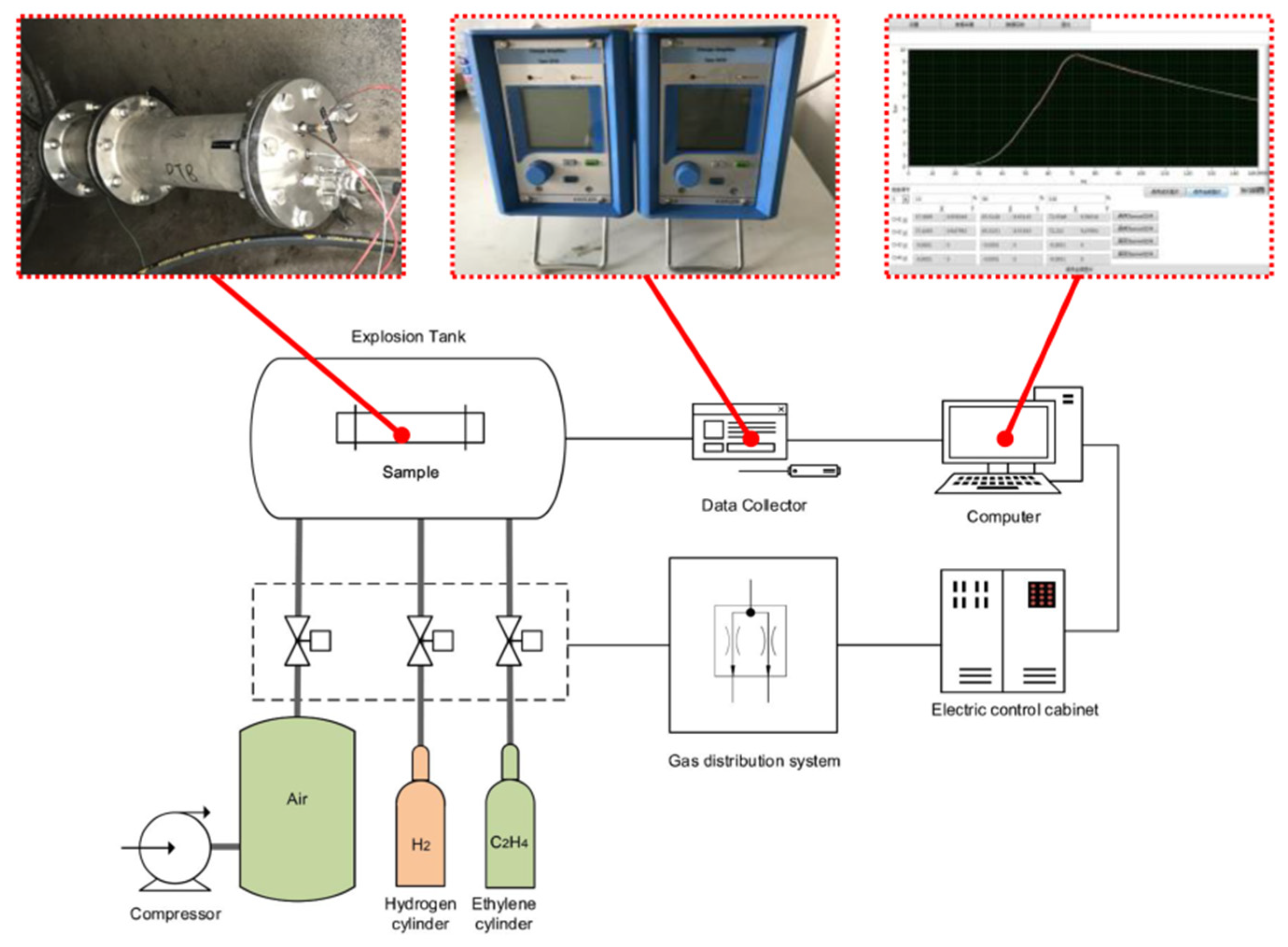
3. Experimental Platform
3.1. Experimental Device
3.2. Experimental Samples
3.2.1. Sample 1
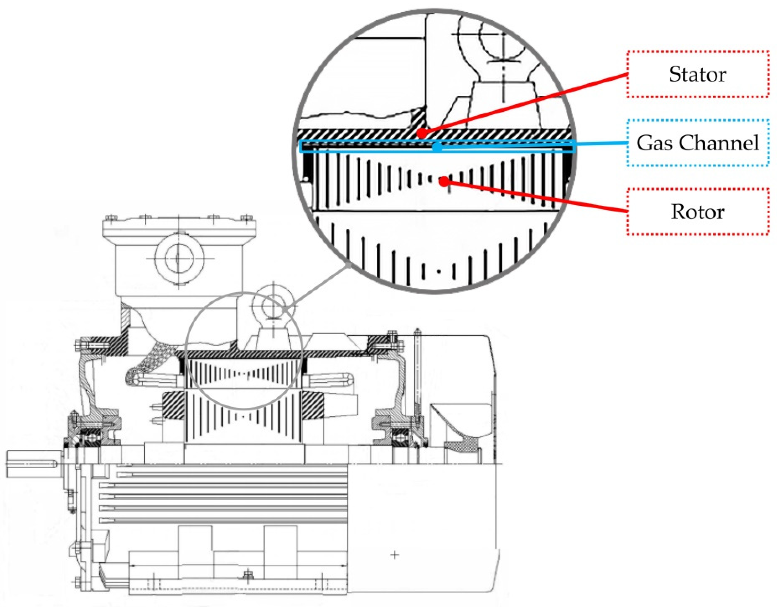
3.2.2. Sample 2
4. Results and Discussions
4.1. Results of Sample 1
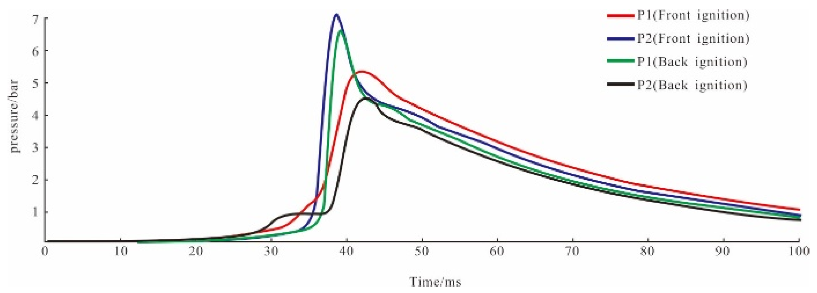
4.2. Results of Sample 2
4.3. The Essence of the Pressure Pilling
5. Conclusions
- (1)
- A significant increase in the explosion pressure was observed in the flameproof enclosures. The pressure on the opposite side was much higher than that on the ignition side.
- (2)
- The rise time of the explosion pressure in the flameproof enclosures was very short, and the pressure in the opposite enclosure reached the maximum value within a few milliseconds.
- (3)
- For a flameproof enclosure, if the interior of the enclosure is divided into cavities with narrow gas channels, this configuration constitutes a sufficient condition for the pressure piling.
- (4)
- When the opposite side is ignited before the value of Pm on the ignition source side (the value of (dp/dt)max on the ignition source side ≠ 0), the pressure piling occurs.
- (5)
- Flameproof enclosures should be designed to have a flame-proof structure for avoiding the occurrence of the pressure piling.
- (6)
- The shell shall be designed to have increased explosion resistance when the layout of the interior components cannot be changed.
- (7)
- Without reassessment, the layout of the internal components of equipment shall not be changed because any careless changes may cause the pressure piling.
Author Contributions
Funding
Institutional Review Board Statement
Informed Consent Statement
Data Availability Statement
Acknowledgments
Conflicts of Interest
Nomenclature
| (do/dt)max | maximum rate of explosion pressure rise in bar/ms |
| EP | explosion pressure index |
| nm | number of moles of gas after explosion, in mole |
| n0 | number of moles of gas before the explosion. |
| P1 | maximum explosion pressure on side 1 in bar |
| P2 | maximum explosion pressure on side2 in bar |
| Pm | maximum pressure in bar |
| P0 | initial pressure in bar |
| Tm | maximum temperature after the explosion in K |
| T0 | initial temperature in K |
| t | pressure rise time in ms |
| v | average pressure rise rate in bar/ms |
References
- International Electrotechnical Commission. Explosive Atmospheres—Part 10-1: Classfication of Areas-Explosive Gas Atmospheres; IEC: Geneva, Switzerland, 2015; pp. 15–18. [Google Scholar]
- International Electrotechnical Commission. International Electrotechnical Vocabulary(IEV)-Part 426:Explosive Atmospheres; IEC: Geneva, Switzerland, 2020. [Google Scholar]
- Ahirwal, B.; Prasad, R.; Kashyap, S.K.; Banerjee, G. Stress analysis due to internal explosion pressure of designed flameproof enclosure for hazardous area. Process Saf. Prog. 2019, 39, e12100. [Google Scholar] [CrossRef]
- International Electrotechnical Commision. Explosive Atmospheres—Part 1: Equipment Protection by Flameproof Enclosures “d”; IEC: Geneva, Switzerland, 2014; pp. 48–59. [Google Scholar]
- Krause, T.; Bewersdorff, J.; Markus, D. Investigations of static and dynamic stresses of flameproof enclosures. J. Loss Prevent. Proc. 2017, 49, 775–784. [Google Scholar] [CrossRef]
- Munro, J.; Xiaoguang, K.; Yingzhen, H. Pressure testing flameproof equipment intended for extremely low temperatures. J. Loss Prevent. Proc. 2017, 49, 769–774. [Google Scholar] [CrossRef]
- Vishwakarma, R.K.; Ranjan, V.; Kumar, J. Comparison of explosion parameters for Methane–Air mixture in different cylindrical flameproof enclosures. J. Loss Prevent Proc. 2014, 31, 82–87. [Google Scholar] [CrossRef]
- Zuo, Q.; Wang, Z.; Zhen, Y.; Zhang, S.; Cui, Y.; Jiang, J. The effect of an obstacle on methane-air explosions in a spherical vessel connected to a pipeline. Process Saf. Prog. 2016, 36, 67–73. [Google Scholar] [CrossRef]
- Kundu, S.K.; Zanganeh, J.; Eschebach, D.; Mahinpey, N.; Moghtaderi, B. Explosion characteristics of methane–air mixtures in a spherical vessel connected with a duct. Process Saf. Environ. 2017, 111, 85–93. [Google Scholar] [CrossRef]
- Maremonti, M.; Russo, G.; Salzano, E.; Tufano, V. Numerical simulation of gas explosions in linked vessels. J. Loss Prevent. Proc. 1999, 12, 189–194. [Google Scholar] [CrossRef]
- Yan, C.; Wang, Z.R.; Jiao, F.; Ma, C. Numerical simulation on structure effects for linked cylindrical and spherical vessels. Simulation 2018, 94, 849–858. [Google Scholar] [CrossRef]
- Wang, Z.; Pan, M.; Wang, S.; Sun, D. Effects on external pressures caused by vented explosion of methane-air mixtures in single and connected vessels. Process Saf. Prog. 2014, 33, 385–391. [Google Scholar] [CrossRef]
- Zhang, K.; Wang, Z.; Jiang, J.; Sun, W.; You, M. Effect of pipe length on methane explosion in interconnected vessels. Process Saf. Prog. 2016, 35, 241–247. [Google Scholar] [CrossRef]
- Di Benedetto, A.; Salzano, E.; Russo, G. Predicting pressure piling by semi-empirical correlations. Fire Saf. J. 2005, 40, 282–298. [Google Scholar] [CrossRef]
- Di Benedetto, A.; Salzano, E. CFD simulation of pressure piling. J. Loss Prev. Proc. 2010, 23, 498–506. [Google Scholar] [CrossRef]
- Zhen, Y.; Wang, Z.; Gong, J. Experimental study of the initial pressure effect on methane-air explosions in linked vessels. Process Saf. Prog. 2017, 37, 86–94. [Google Scholar] [CrossRef]


| Gas | Molecular Symbol | Volume Ratio | Ambient Humidity (%) | Ambient Temperature (°C) | Initial Pressure (Bar) | Number of Trials |
|---|---|---|---|---|---|---|
| Ethylene | C2H4 | 8 ± 5% | 40 ± 2 | 20 ± 5 | 1.0 | 5 |
| Ignition Position | Motor Status | Pressure Position 1 | Pressure Position 2 | Ambient Humidity (%) | Ambient Temperature (°C) | Initial Pressure (bar) | Number of Trials |
|---|---|---|---|---|---|---|---|
| Front cover | Rest | Front cover | Rear cover | 40 ± 2 | 20 ± 5 | 1.0 | 5 |
| Front cover | Running | Front cover | Rear cover | 40 ± 2 | 20 ± 5 | 1.0 | 5 |
| Rear cover | Rest | Front cover | Rear cover | 40 ± 2 | 20 ± 5 | 1.0 | 5 |
| Rear cover | Running | Front cover | Rear cover | 40 ± 2 | 20 ± 5 | 1.0 | 5 |
| Sample | The Maximum Explosion Pressure Value (in bar) | Pressure Rise Time (in ms) | The Maximum Rate of Pressure Rise (in bar/ms) | |||
|---|---|---|---|---|---|---|
| Side 1 | Side 2 | Side 1 | Side 2 | Side 1 | Side 2 | |
| Sample 1 (Configuration 1) | 5.67 | 5.80 | 64.41 | 64.32 | 0.09 | 0.09 |
| Sample 1 (Configuration 2) | 6.93 | 11.85 | 20.42 | 1.51 | 2.95 | 7.84 |
| Ignition Place | The maximum Explosion Pressure Value (in bar) | Pressure Rise Time (in ms) | The Maximum Rate of Pressure Rise (in bar/ms) | |||
|---|---|---|---|---|---|---|
| Front Cover | Back Cover | Front Cover | Back Cover | Front Cover | Back Cover | |
| Front cover | 5.14 | 6.85 | 8.57 | 3.02 | 0.06 | 2.26 |
| Rear cover | 6.08 | 4.12 | 2.23 | 11.85 | 2.73 | 0.35 |
Publisher’s Note: MDPI stays neutral with regard to jurisdictional claims in published maps and institutional affiliations. |
© 2021 by the authors. Licensee MDPI, Basel, Switzerland. This article is an open access article distributed under the terms and conditions of the Creative Commons Attribution (CC BY) license (https://creativecommons.org/licenses/by/4.0/).
Share and Cite
Li, D.; Dai, S.; Lin, T. Evaluation of the Explosion Pressure Parameters in Flameproof Enclosures under the Pressure Piling Condition. Energies 2021, 14, 8156. https://doi.org/10.3390/en14238156
Li D, Dai S, Lin T. Evaluation of the Explosion Pressure Parameters in Flameproof Enclosures under the Pressure Piling Condition. Energies. 2021; 14(23):8156. https://doi.org/10.3390/en14238156
Chicago/Turabian StyleLi, Dong, Shijie Dai, and Tao Lin. 2021. "Evaluation of the Explosion Pressure Parameters in Flameproof Enclosures under the Pressure Piling Condition" Energies 14, no. 23: 8156. https://doi.org/10.3390/en14238156