Abstract
In cold and humid regions, ice accretion sometimes develops on the blades of wind turbines. Blade icing reduces the power generation of the wind turbine and affects the safe operation of the wind farm. For this paper, ultrasonic micro-vibration was researched as an effective de-icing method to remove ice from the wind turbine blade surface and improve the efficiency of wind turbine power generation. A blade segment with NACA0018 airfoil and the hollow structure at the leading edge was designed. The modal analysis of the blade was simulated by ANSYS, and the de-icing vibration mode was selected. Based on the simulation results, the blade segment sample with PZT patches was machined, and its natural frequencies were measured with an impedance analyzer. A return-flow icing wind tunnel system, and a device used to measure the adhesive strength of ice covering the airfoil blade, were designed and manufactured. The experiments on the adhesive strength of the ice were carried out under the excitation of the ultrasonic vibration. The experimental results show that the adhesive strength of the ice, which was generated under the dynamic flow field condition, was lower than the ice generated by water under the static flow field condition. Under the excitation of the ultrasonic vibration, the adhesive strength of the ice decreased. When the excitation frequency was 21.228 kHz, the adhesive strength was the lowest, which was 0.084 MPa. These research findings lay the theoretical and experimental foundations for researching in-depth the application of the ultrasonic de-icing technology to wind turbines.
1. Introduction
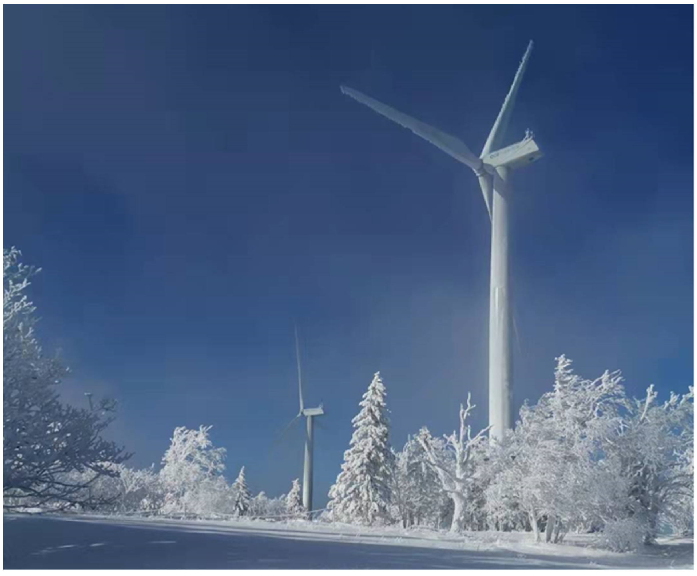
In recent years, policies on energy efficiency and energy-saving have been made in order to decrease energy consumption [1]. Therefore, renewable energies, such as wind energy and solar energy are receiving increasing attention. Wind energy, as an energy source, has the benefits of being clean, free and renewable. It has been widely used in the field of wind power generation, and wind turbines have the advantages of a short building period and flexibility of installation. Therefore, in recent decades, thousands of wind turbines have been installed around the world. However, with the rapid development of technology and the aging of many wind turbines, the repowering technology for them needs to be further developed throughout the world. With regards to repowering, the EU is ahead of the world [2,3,4]. Extreme conditions decrease performance and accelerate the aging of wind turbines. For instance, when wind turbines work in cold and humid regions, ice accretion often develops on the surface of the blades [5,6,7]. It changes the airfoil profile of the blade, which leads to the degradation of the aerodynamic performance of the wind turbine and the reduction of power generation efficiency. In addition, the icing event increases the weight of the blade and shortens the lifespan of the wind turbine [8]. Some icing events of the wind turbines are shown in Figure 1. The wind farms were located in the Heilongjiang Province, in the northeast of China, with the ice accretion developing in the winter of 2019. Therefore, this research on anti- and de-icing technologies for the wind turbine blades is significant and necessary for the regions affected by blade icing.

Figure 1.
Examples of icing on wind turbines.
In recent years, scholars have conducted research utilizing icing tests on structures with an airfoil profile, such as the wind turbine blades and airplane wings. Li Yan carried out an icing test on a wind turbine blade and explored the distribution of icing on the blade surface and the cylinder under the rotational states [9,10]. Yi Xian conducted theoretical research on the effect of icing on the aerodynamic performance of an airplane wing and proposed a numerical simulation method for icing on structures with an airfoil profile. Based on the method, simulation software on blade icing was developed [11]. The research findings show that icing accretion on the airfoil structure leads to a decrease in the lift coefficient and an increase in the drag coefficient, and the aerodynamic performance significantly degrades. Therefore, developing anti- and de-icing methods can promote the power generation efficiency of wind.
At present, there are several types of de-icing methods being researched. They are the electro-thermal de-icing method, the fluid-thermal de-icing method, the pneumatic impulse de-icing method, the surface coating de-icing method, the ultrasonic vibration de-icing method, and so on. Among these methods, the electro de-icing method needs massive energy [12]. Since the wind turbine is a device for generating electric power, this method significantly decreases the efficiency of power generation. The surface coating method is a type of active de-icing method. The blade surface of the wind turbine is covered by a hydrophobic material layer. This method reduces the icing rate but cannot completely get rid of icing. Moreover, the adhesive strength of the coating is too low, which easily falls off the blade surface [13] and, consequently, loses the capability of de-icing. The fluid-thermal de-icing method uses hot fluid, such as hot air or hot liquid, to heat the icing blade surface in order to remove the ice. This method has a complex system and high weight due to the many tubes used to transmit the fluid. In addition, the volume of the air pump or the water pump is large, therefore, necessitates a large space [14]. The pneumatic impulsive de-icing method is similar to the fluid-thermal de-icing method, which also needs tubes to transmit air. This type of de-icing method uses an inflatable boot on the leading edge of the blade that, when inflated, dislodges accumulated ice. It also has a complex system and high weight [15]. Therefore, the above-mentioned methods are not suited to wind turbine de-icing. In contrast, the ultrasonic de-icing method has the advantages of low energy consumption, a simple structure and easy installation, which is suited to the field of wind power generation. In the early research, the ultrasonic de-icing method aimed, mainly, to remove the ice covering the surfaces of helicopter blades [16,17]. The research methods included the analytic method, the simulation method and the experimental method. A mathematical model of the shear stress, at the interface between the ice and the plate substrate, was established by the analytic method. However, the model is established based on the theory of the elastic wave spreading on the plate without a boundary, which expresses the relationship between the interface shear stress concentration (ISSC) and the wave velocity [18]. Jifeng Zhang studied the ultrasonic de-icing of a plate with a coating based on the mathematical model. The theoretical model provided the reference for the design principle of coating and ultrasonic parameters required for efficient de-icing [19]. The simulation method establishes the solid model of the blade and analyzes the de-icing vibration mode and the distribution of shear stress which is at the interface between the ice and the substrate. Jose Palacios researched the ultrasonic de-icing of a plate element. He simulated the distribution of the shear stress at the interface between the small piece of ice and the plate substrate [20]. Li Yan simulated the variation and the distribution of the shear stress with the excitation frequency. When the shear stress at the adhesive interface alternates positively and negatively, the de-icing shear stress is highest [21]. Li Luping examined the effect of the space between the PZT patches on the shear stress at the adhesive interface by simulation. The simulation result showed that there was the optimum space that can generate higher shear stress [22]. The experimental method carries out the ultrasonic de-icing test in low-temperature equipment, such as a refrigerator or an icing wind tunnel. However, in the existing ultrasonic de-icing experiments, most of the icing conditions are static flow fields in a refrigerator [23,24]. The dynamic flow field condition, such as a wind tunnel, is seldom used [25]. In real icing conditions for wind turbines, the super-cooled water droplets, moving with the airflow, impact the blade surface. Therefore, the static flow field cannot simulate real icing conditions. In addition, the adhesive strength of the ice, covering the blade surface and generated in the dynamic flow field, is seldom researched.
In this paper, the ultrasonic de-icing method of wind turbine blades was researched by simulation and experimentation. An innovative airfoil blade structure with PZT patches was designed, and the vibration mode and its natural frequency were calculated by ANSYS. Based on the theoretical calculation results, a sample of the blade segment was manufactured, and an experimental system, for icing and de-icing, was built. The adhesive strengths of ice under different excitation frequencies were tested by a self-developed device in order to validate the de-icing effect of ultrasonic vibration. The research findings provide the theoretical and experimental foundations for exploring in more depth the ultrasonic de-icing method of wind turbines.
2. Simulation
In the field of wind power generation, most of the wind turbines, including the horizontal wind turbine and the vertical wind turbine, are lift-type turbines. Therefore, the lift-type airfoil blade was selected as the blade for research. For lift-type airfoils, the NACA series airfoils are widely used. This series of airfoils stem from the airplane, which are developed by the National Advisory Committee for Aeronautics (NACA) in the USA. For NACA series airfoils, there are two types of structures, the symmetrical structure and the asymmetrical structure. For carrying out basic research, the symmetrical one was selected. Additionally, the aerodynamic characteristics of the NACA0018 airfoil are better compared with the other symmetrical ones, and this type of airfoil is easily manufactured due to its simple structure. Therefore, an aluminum blade segment with the airfoil of NACA0018 was selected for this research. In addition, the aluminum material has the characteristics of low density, high thermal conductivity and stable heat transfer performance. In some cases, the blades of small-scale wind turbines are made of aluminum material which is why the aluminum blade was selected as the research object in the present study.
2.1. Simulation Model of the Blade
The sketch map of the blade is shown in Figure 2.

Figure 2.
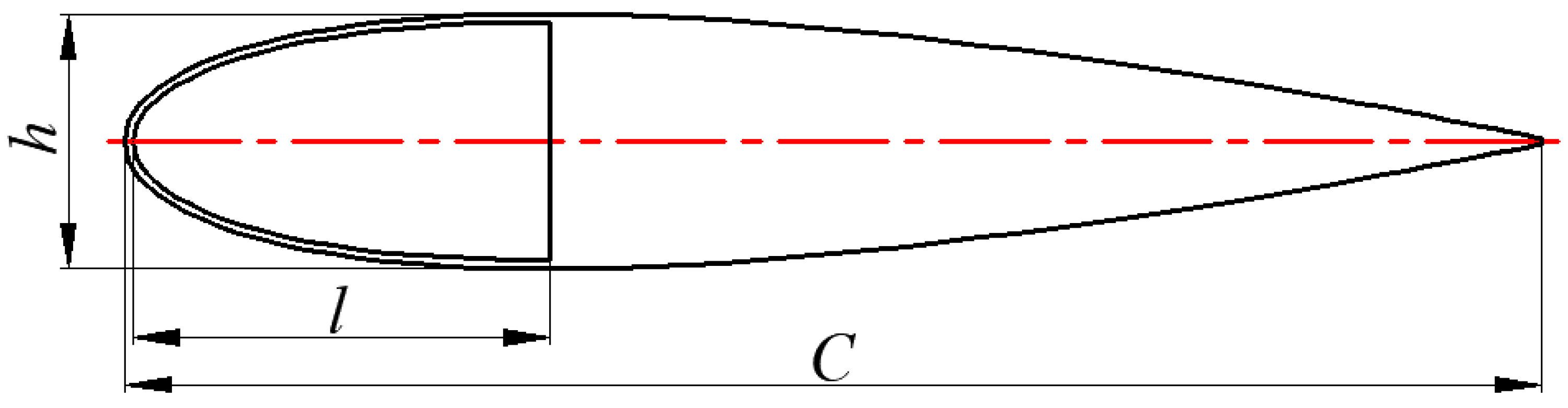
Sketch map of the blade for the simulation.
As shown in Figure 2, the leading edge of the blade segment has a hollow structure, which was used to lay out the PZT patches. In previous works, research findings show that icing mainly concentrates on the leading edge of the horizontal axis wind turbine blade. Therefore, in this study, the leading edge, with the hollow structure, was designed. The chord length l at the position of the hollow structure was 30% of the whole blade chord length C.
According to the size of the icing wind tunnel in our research group, the chord length of the blade segment was 250 mm. The maximum thickness of the blade segment h was 45 mm. The size of the wingspan was 40 mm, and the thickness of the wall at the leading edge was 1.5 mm.
2.2. Simulation of the De-Icing Vibration Mode
For getting the de-icing vibration mode, the model analysis of the blade was carried out by ANSYS. ANSYS is a commercial finite element software, which is widely used in the fields of machinery, chemical industry, aeronautics, astronautics and civil engineering. In the present study, the principle of the ultrasonic de-icing method was based on mechanical vibration, which belongs to the field of mechanical design [26,27]. Many vibration analyses are carried out by ANSYS and many scholars have also researched ultrasonic de-icing technologies using this simulation software [28,29]. According to the size of the blade segment, the blade model was established in ANSYS. In the procedure of the simulation, the density of the aluminum material was 2.7 × 10³ kg/m3, and the element type for the blade was SOLID187. The first ten vibration modes of the blade segment are shown in Figure 3.

Figure 3.
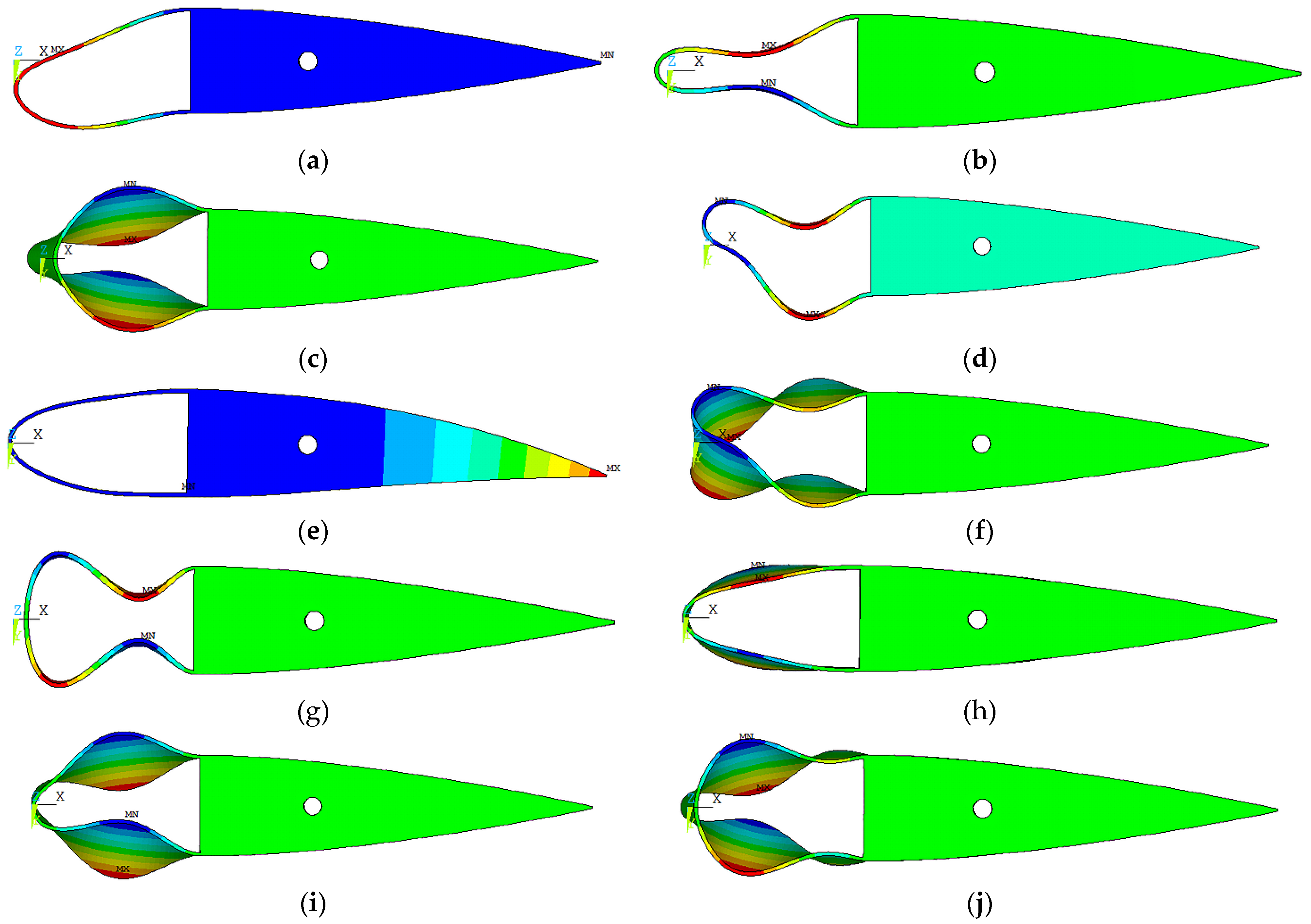
The first ten vibration modes of the blade segment. (a) The first vibration mode (428 Hz); (b) The second vibration mode (1257 Hz); (c) The third vibration mode (1716 Hz); (d) The fourth vibration mode (2266 Hz); (e) The fifth vibration mode (2857 Hz); (f) The sixth vibration mode (2994 Hz); (g) The seventh vibration mode (3474 Hz); (h) The eighth vibration mode (3641 Hz); (i) The ninth vibration mode (3687 Hz); (j) The tenth vibration mode (3998 Hz).
As shown in Figure 3, in the first ten vibration modes, the leading edge of the blade segment had several kinds of deformations. These included bending, torsional and coupled deformation. According to previous research findings, the adhesive strength of the ice, at the tangential direction or the direction parallel to the substrate surface, is lower than the ones in the other directions. Therefore, most of the mechanical de-icing methods are developed based on the adhesive characteristic of ice. When the shear stress at the interface between the ice and the substrate, which is generated by the external force, is higher than the adhesive shear stress of the ice, the ice falls off the substrate. The ultrasonic de-icing method is also based on the de-icing mechanism. When the icing blade vibrates under the excitation of the PZT patches, the shear stress generates at the adhesive interface with the deformation of the blade, which can decrease the adhesive strength or remove ice. In previous research on ultrasonic de-icing of the icing plate, it was found that when the distribution of the shear stress at the adhesive interface alternates positively and negatively, the effect of the ultrasonic de-icing on the decrease in the adhesive strength of the ice is obvious [21]. Therefore, based on this conclusion, the bending deformation of the leading edge, alternating positively and negatively, was selected as the de-icing vibration mode for the blade segment because the shear stress is high under the conditions that produce the bending deformation.
As shown in Figure 3g, in the seventh vibration mode, the bending amplitude of the leading edge alternates positively and negatively, which meets the condition of the de-icing vibration mode. However, for this vibration mode, the natural frequency is just 3474 Hz, which is far lower than the ultrasonic frequency (≥20,000 Hz). Therefore, the vibration mode cannot satisfy the frequency of ultrasonic de-icing. According to the first ten vibration modes, the vibration modes in the scope of ultrasonic frequency were calculated. When the natural frequency was 22,779 Hz, the bending vibration mode met the conditions for ultrasonic de-icing. The vibration mode is shown in Figure 4.

Figure 4.
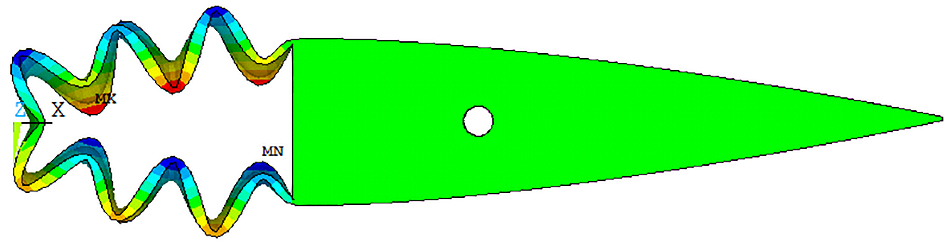
Ultrasonic de-icing vibration mode.
As shown in Figure 4, the leading edge of the blade is in the bending vibration mode. The amplitude of the bending deformation alternated positively and negatively. In addition, along the direction of the wingspan, the amplitude of the bending deformation was the same.
For exciting the bending deformation of the blade segment as shown in Figure 4, the PZT patches were located at the maximum amplitude of the leading edge. The computer model of the blade segment with the PZT patches is shown in Figure 5.
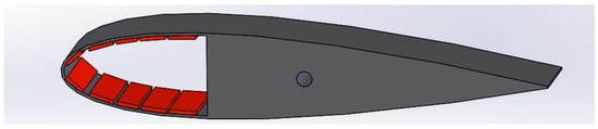
Figure 5.
Blade model with the PZT patches.
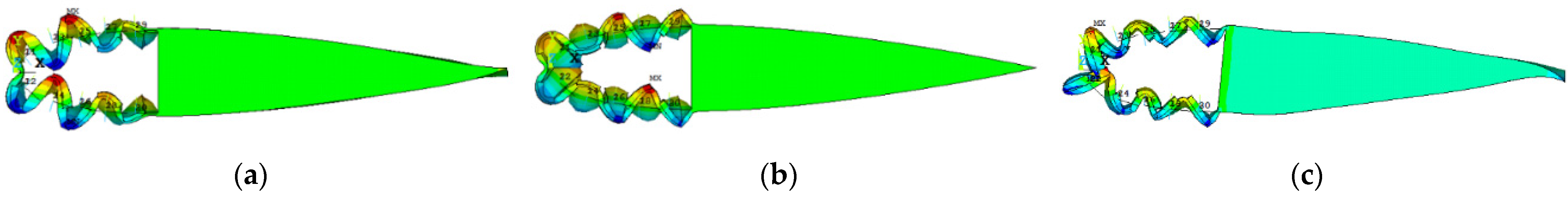
As shown in Figure 5, the PZT patches were symmetrically located in the hollow space of the leading edge of the blade. After the installation of the PZT patches, the natural frequencies of the blade varied with the stiffness and mass of the leading edge. Therefore, the vibration modes of the blade segment with the PZT patches were calculated in the scope of the ultrasonic frequency again. In comparison with the simulation results of the blade segment without the PZT patches, three kinds of vibration modes were selected, and their natural frequencies were 21,935.6 Hz, 25,094 Hz and 27,896.9 Hz respectively. In these vibration modes, the vibration amplitudes of the bending deformations of the leading edges approximately alternated positively and negatively, which are shown in Figure 6.
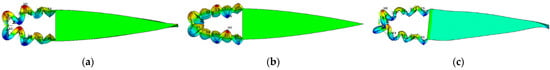
Figure 6.
Vibration modes of the leading edge with the PZT patches. (a) The 51st vibration mode (21,935.6 Hz); (b) The 61st vibration mode (25,094 Hz); (c) The 68th vibration mode (27,896.9 Hz).
3. De-Icing Experiment
According to the simulation results, the ultrasonic de-icing experiment on the icing blade segment was conducted. The adhesive shear strength of ice on the blade segment was measured.
3.1. Blade Sample
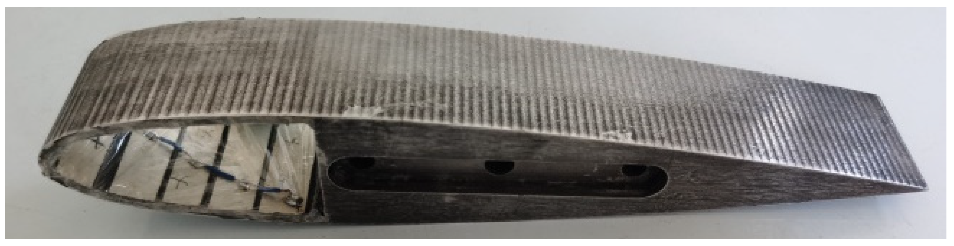
According to the simulation results, the sample of the blade segment with the PZT patches was designed and machined, which is shown in Figure 7.
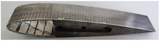
Figure 7.
Sample of the blade.
As shown in Figure 7, the model of the piezoelectric ceramic was PZT4, which is a type of powering piezoelectric ceramic and is often used in the design of transducers. For making the vibration amplitude of the bending deformation alternate positively and negatively, the polarization directions of the neighboring PZT patches were different, which were also laid out positively and negatively.
3.2. Experimental System
In this paper, a de-icing experimental system with an ultrasonic device for the blade segment was designed and built. It was composed of two parts, which were the icing sub-system and ultrasonic de-icing sub-system.
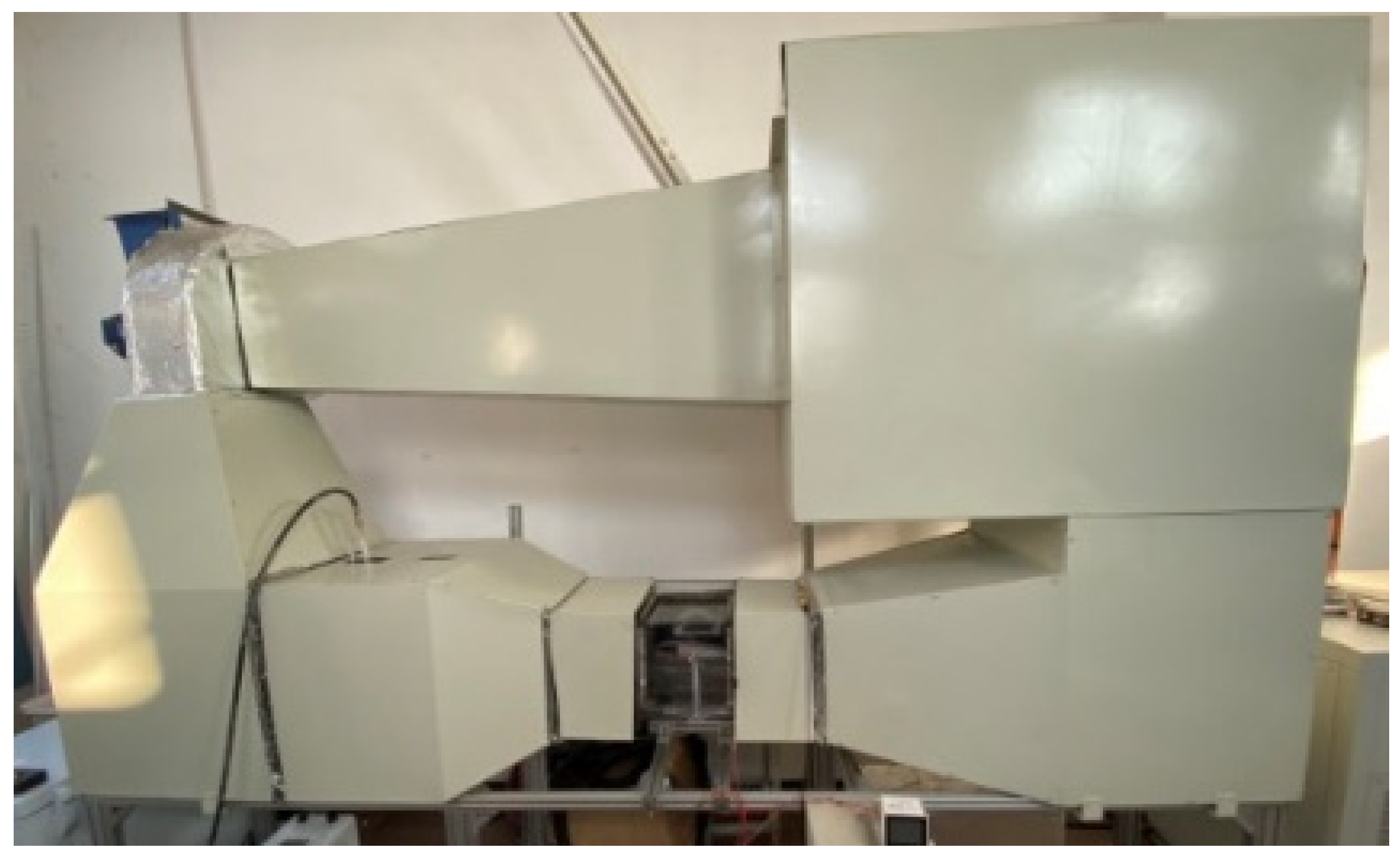
The icing sub-system is shown in Figure 8. It is a self-designed return flow icing wind tunnel, which is composed of the steady flow section, the mix section, the test section, the cooling system and the spraying system. The icing wind tunnel was used to simulate the icing condition of the wind turbine. In real conditions for the icing of wind turbine blades to occur, the water droplets in the low-temperature environment flow with the air and impact the blade surface. The type of icing under this type of condition is different from the one generated by water under the refrigerator condition. It is the reason that the icing wind tunnel was used in the present study. There were three basic steps for designing the icing wind tunnel.

Figure 8.
Icing wind tunnel.
3.2.1. Design of the Reflux Tunnel
The kinetic energy of the flowing air in the reflux tunnel was provided by a centrifugal fan, model CF-3.5, with 3 kW of power. The wind speed was modulated by a variable-frequency drive (VFD), model YVF2-100S-4. The test section could be moved into different sizes in order to change the wind speed. According to the power of the fan and the maximum design wind speed, 20 m/s, the cross area of the test section was designed as 250 × 250 mm2.
3.2.2. Design of the Cooling System
A refrigeration compressor, model is BITZER KP-4TES9Y, with 6.62 kW of power, was selected to cool the air in the wind tunnel. According to the volume of the wind tunnel, the refrigerating capacity at −20 °C was 7.76 kW and the wind speed was 22 m/s. Therefore, the above conditions met the demands of the icing test.
3.2.3. Design of the Spray System
The spray system was located in the mix section. A high-pressure mist nozzle was used in the spray system. The diameter of its orifice was 0.1 mm. The distilled water was pumped by a water pump. In the study, the water pressure was 4 MPa, and the flow rate of the nozzle was 19~20 mL/min. Under these conditions, the Medium Volume Diameter (MVD) was approximately 50 μm.
The working parameters of the icing wind tunnel are listed in Table 1.

Table 1.
Working parameters of the icing wind tunnel.
As listed in Table 1, the icing wind tunnel system met the icing temperature conditions for glaze ice, mixing ice and rime ice, and the scope of the wind speed was wide, which met the working conditions of the wind turbine.
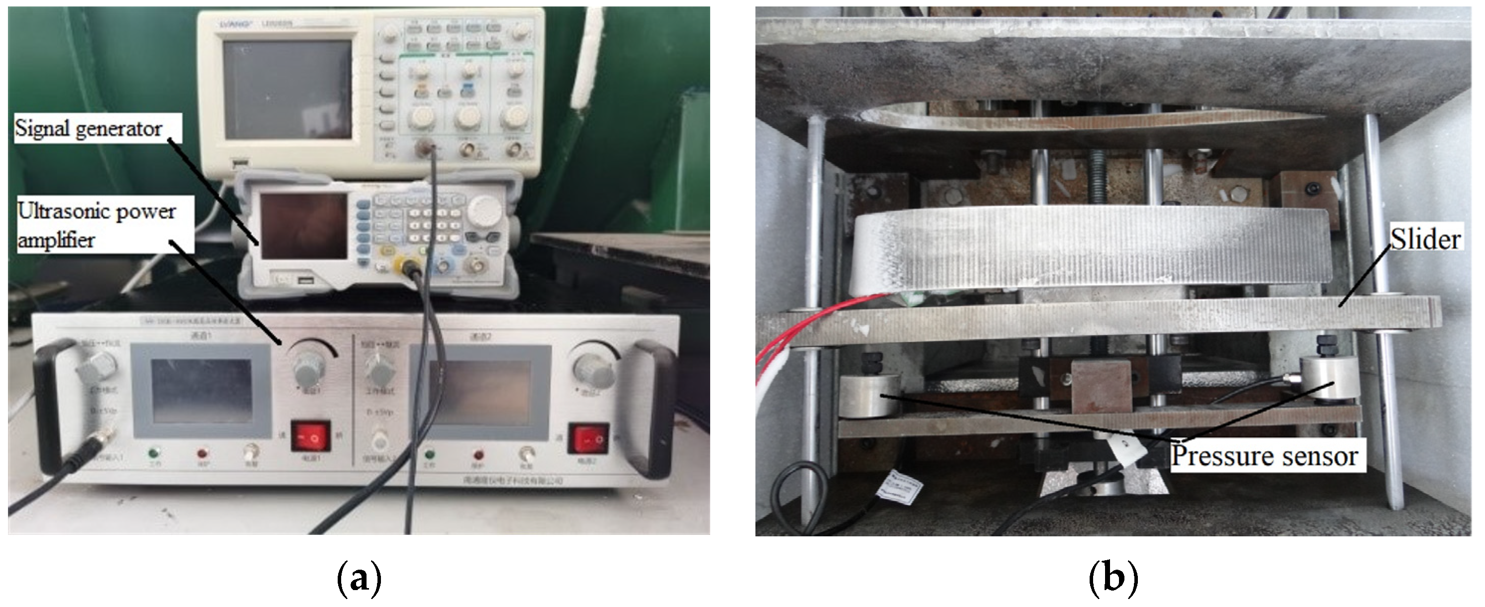
The ultrasonic de-icing sub-system included the adhesion measurement device and the ultrasonic excitation device. Until now, seldom research has been carried out to measure the adhesive strength of ice accreting on the blade surface. In the present study, an adhesion measurement device was designed and used to measure the adhesive strength of the ice on the airfoil blade segment. The ultrasonic excitation device was used to excite the ultrasonic vibration of the blade. The ultrasonic de-icing sub-system was used to measure the adhesive strength of the ice on the airfoil blade segment under ultrasonic vibration, which is shown in Figure 9.
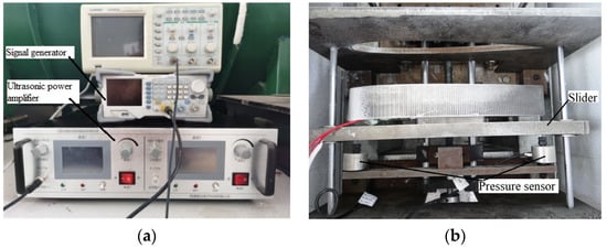
Figure 9.
Ultrasonic de-icing sub-system. (a) Ultrasonic excitation device; (b) Adhesion measurement device.
As shown in Figure 9a, the ultrasonic excitation device was composed of the signal generator and the ultrasonic power amplifier. The signal generator, model RIGOL DG1022Z, was used to generate the high-frequency signal. The ultrasonic power amplifier, model LONG YI DGR-3001, was used to amplify the voltage and the power of the signal from the signal generator and excite the PZT patches. Under the excitation of the PZT patches, the blade segment vibrated. From Figure 9b, the shear method was used to measure the adhesive strength of the ice on the blade segment surface. After the process of the icing test, the icing blade was mounted on the slider, which moved along the parallel rails. The slider was driven by the screwdriver where two pressure sensors were mounted symmetrically. When the icing blade went through the airfoil hole matched with the blade, the ice adhering to the blade surface was squeezed by the shear force. The maximum value of the shear force could be acquired by the pressure sensors, which was also the maximum adhesive shear strength of the ice. The brand-new measurement method proposed an opportunity to research the effect of ultrasonic vibration on the adhesive characteristic of ice.
3.3. Measurement of the Natural Frequency
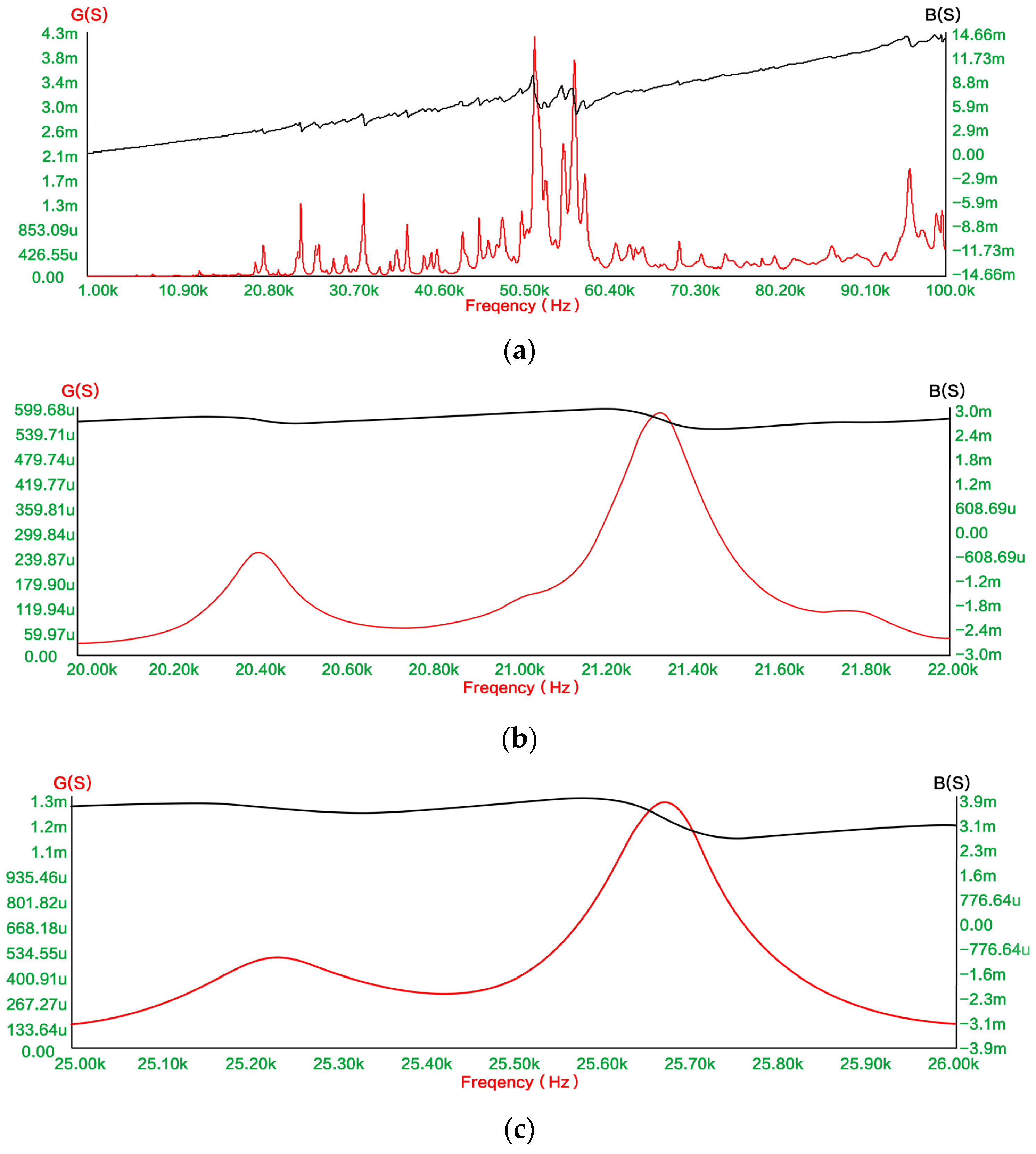
Before conducting the icing test, the natural frequencies of the blade sample with the PZT patches were measured by the impedance analyzer, model ZX70A. The measurement results provided the reference for the ultrasonic de-icing test, which are shown in Figure 10.

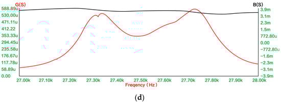
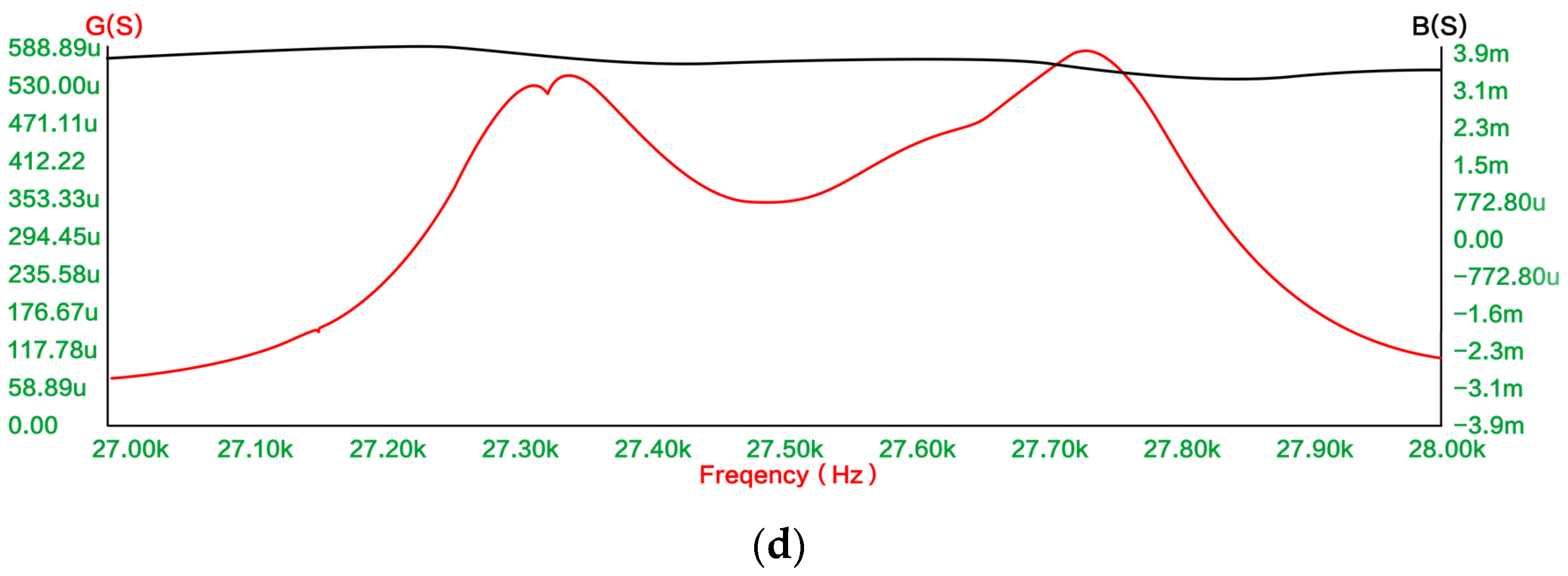
Figure 10.
Measurements of the natural frequencies of the blade segment with the PZT patches. (a) 0~100 kHz; (b) 20~22 kHz; (c) 25~26 kHz; (d) 27~28 kHz.
As shown in Figure 10a, there were many natural frequencies for the blade segment in the scope of 0~100 kHz. According to the simulation results, three scopes of the natural frequencies, which were 20~22 kHz, 25~26 kHz and 27~28 kHz, were measured in detail again, and the measurements are shown in Figure 10b–d, respectively. The natural frequencies, which were measured in these scopes, are listed in Table 2.
Table 2.
Natural frequencies of the blade.
As listed in Table 2, there are discrepancies between the simulation results and the measurement results. Two factors contributed to the discrepancies.
- (1)
- The differences in the size and the material properties between the blade model and the blade sample. For the blade sample, the material property is not completely the same as the one in the simulation, such as the density, the Yang’s Elastic Modulus and the Poisson’s ratio. In addition, the manufacturing error also led to the size discrepancy between the model and the sample;
- (2)
- The differences in the size, the material properties and the assembly method between the PZT patch model and the PZT patch sample. The material properties of the PZT patch sample are different from the one in the simulation model, such as the permittivity, the density, the piezoelectric constant, the stiffness matrix, and so on. In addition, the PZT patch samples also have discrepancies with each other because of the error of the processing technique. With regards to the PZT assembly, the PZT patches were pasted on the inner surface of the leading edge with epoxy resin. There was a glue sheet between the PZT patch and the blade. However, in the process of the simulation, the PZT patches should ideally be connected with the blade by the VGLUE command. Therefore, there was a discrepancy between the simulation model and the sample.
3.4. Experimental Scheme
According to the measurement results of the natural frequencies, the experimental scheme on the ultrasonic de-icing test of the airfoil blade segment is listed in Table 3.
Table 3.
Experimental scheme on the icing test of the airfoil blade.
As listed in Table 3, the ultrasonic de-icing test of the airfoil blade was carried out under the rime ice condition, and the adhesive strength of the ice on the blade surface was measured under the different excitation frequencies in order to validate the de-icing effect of ultrasonic vibration.
3.5. Experimental Results
According to the experimental scheme, the de-icing test of the blade segment was conducted. The ice accreting on the blade surface is shown in Figure 9b. As shown in Figure 9b, the ice mainly covered the leading edge for the static blade segment. The type of ice in the study is mixing ice, which is composed of glaze ice and rime ice. In the initial stage of icing the test, the type of ice was rime ice. With the increases in the icing time and the thickness of the ice, the type of ice gradually became glaze ice. The reason for this result is that when the water droplets made contact with the blade surface directly at the initial icing stage, they froze in a short time due to the high heat transfer coefficient of the aluminum material which was 237 W/(m·K). The rapid decrease in the temperature makes the water droplet freeze fast. Therefore, the type of ice formed was rime ice. With the increase in the thickness of the ice, when the water droplets made contact with the ice, they did not freeze instantly due to the low heat transfer of the ice which was 2.22 W/(m·K); therefore, the ice formed was glaze ice.
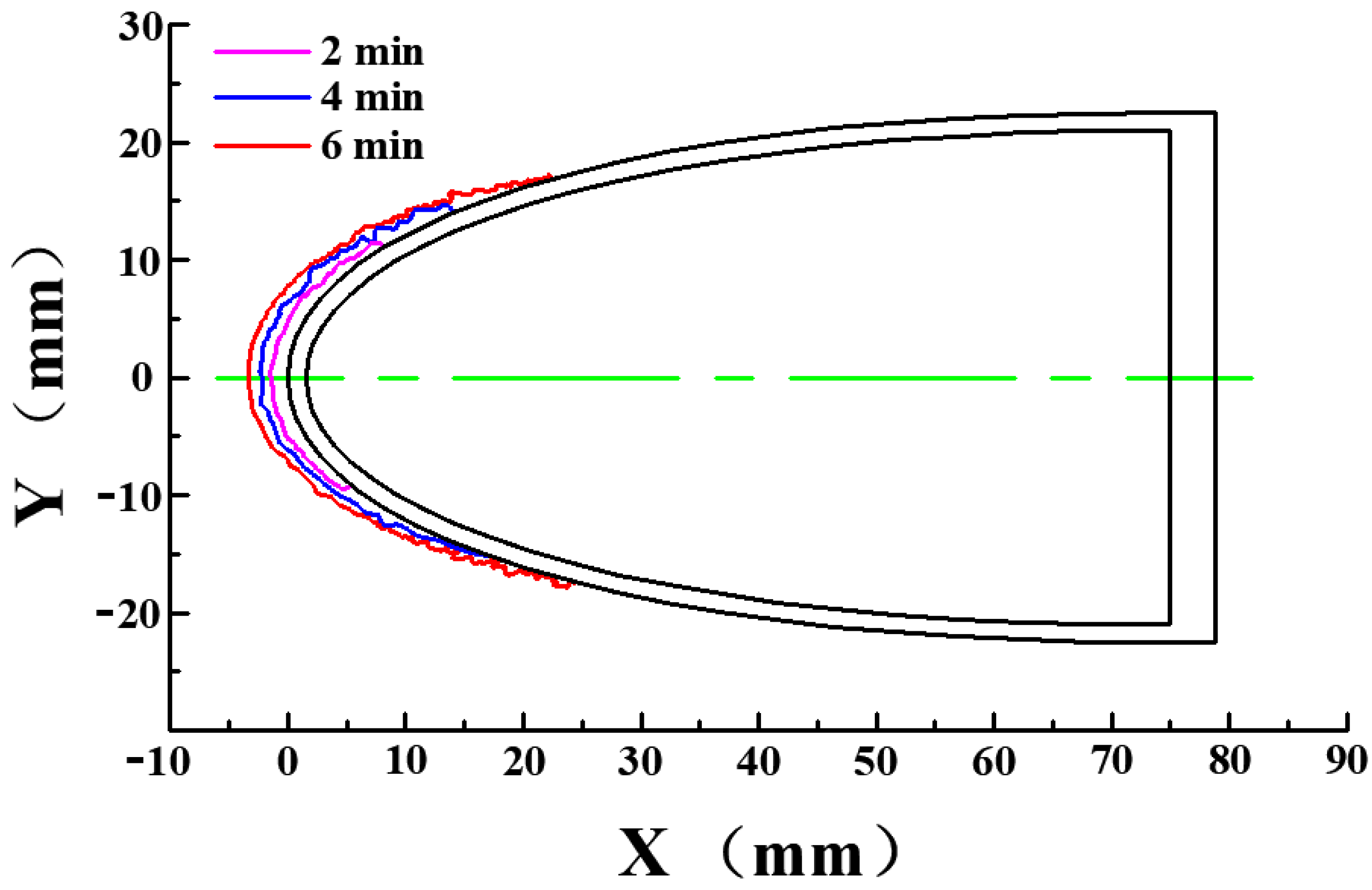
In the process of icing, the icing shape was captured by a high-speed camera, model Phantom v5.1. The time interval of acquisition is 2 min. The profile of ice at each acquisition time was drawn and is shown in Figure 11. As shown in Figure 11, the ice grew layer by layer with the maximum thickness of the ice located at the forefront of the leading edge. The icing surface was located at a ratio of 10% of the chord length.
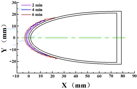
Figure 11.
Ice on the blade surface.
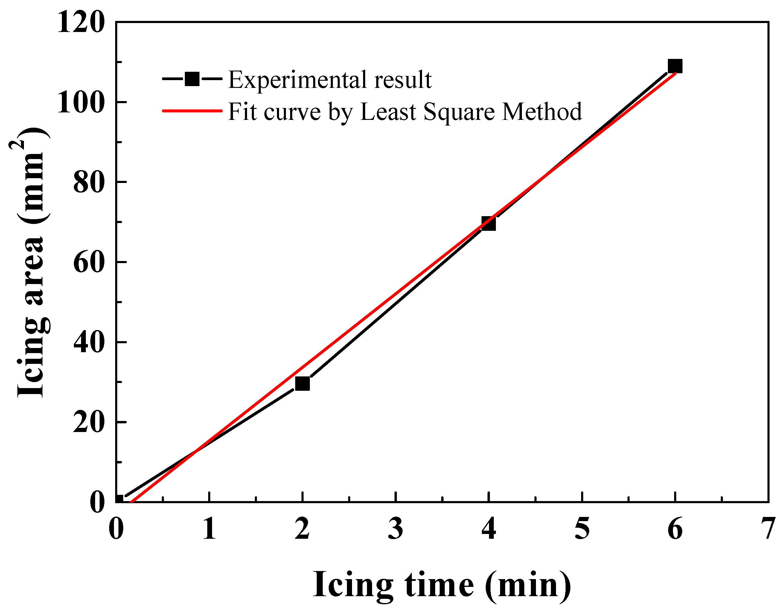
The variation of the icing area is shown in Figure 12. The icing area was the area of the cross-section of ice as shown in Figure 11.
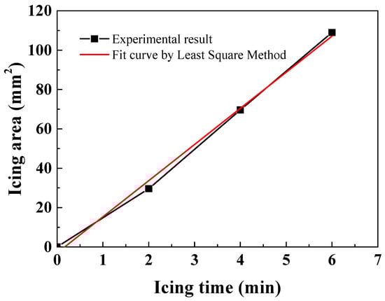
Figure 12.
Variation of the icing area with the icing time.
As shown in Figure 12, the icing area grew approximately linearly with the icing time. A fit curve was drawn by the Least Square Method based on the experimental results. From the fitting result, the growth rate of the ice area was approximately 18.35.
After the icing test, the adhesive strength of the ice, under different excitation frequencies, was measured by the self-designed de-icing device shown in Figure 9. According to the measurements of the shear force and the area of the ice covering on the blade surface, the adhesive shear stress was calculated by Equation (1):
where τ is the shear stress of the ice; F is the shear force of the ice covering the blade surface; S is the area of ice covering the blade surface.
τ = F/S
According to Equation (1), the shear stresses of the ice under the different excitation frequencies were calculated and are listed in Table 4. The variation of the adhesive shear stress with excitation frequency is shown in Figure 13.
Table 4.
Adhesive shear stress under the excitation frequencies.

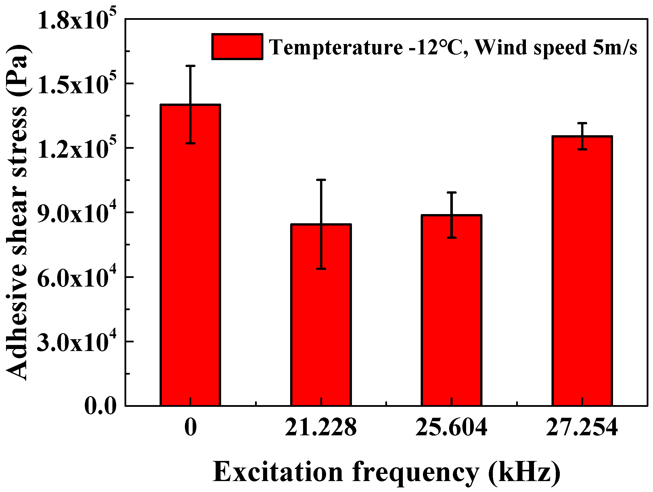
Figure 13.
Adhesive shear stress of the ice.
As shown in Figure 13, under the no vibration condition, the adhesive shear stress of the ice was approximately 0.14 MPa. This research finding shows that the adhesive strength of the ice, generated under the dynamic flow field, was lower than for the glaze ice, which was frozen by water under the static air condition, which was approximately from 0.3~1.7 MPa [30]. The reason for this result is that the space-filling efficiency of the ice generated by the water droplets was lower than that generated by the water. According to the results of the icing test, the type of ice generated in the icing wind tunnel was mixing ice, which was composed of rime ice and glaze ice. For the rime ice, generated from the water droplets, there was space between the iced water droplets. This led to the decrease in the contact area of the ice and the strength of the ice, which resulted in the low adhesive shear stress. In contrast, for the glaze ice generated in the refrigeration system, generated from the continuous flow of water, there was no space in the body of ice, and the contact area with the substrate was large.
Moreover, when the icing blade vibrated under the different ultrasonic frequencies, the adhesive shear stresses were all lower than without ultrasonic vibration. This validated that ultrasonic vibration has the de-icing effect. When the excitation frequency was 21.228 kHz, the adhesive shear stress was the lowest, which was approximately 0.084 MPa. The experimental result validated the simulation result shown in Figure 6a. In this vibration mode, the leading edge symmetrically bent along the blade chord without any other types of bending modes along the span. Meanwhile, the PZT patches were located at the maximum bending amplitude. In this case, the bending deformation was the largest, which resulted in the high shear stress at the adhesive interface. In contrast, for the vibration mode in Figure 6b, although the leading edge symmetrically bent along the blade chord, there was bending deformation along the span, which may have decreased the adhesive shear stress of the ice along the span. Additionally, for the vibration mode in Figure 6c, the leading edge asymmetrically bent along the blade chord, and the PZT patches were not located at the maximum bending amplitude. That was why the adhesive shear stress was the highest among these vibration modes.
4. Conclusions
In this paper, the adhesive strength of ice on the airfoil blade and the ultrasonic de-icing method of the blade were researched, and several conclusions are summarized as follows:
- (1)
- An airfoil blade segment with a hollow structure was designed, and the model analysis of it was calculated. The bending vibration mode, in which the vibration amplitude alternates positively and negatively, was selected as the de-icing vibration mode;
- (2)
- A return-flow icing wind tunnel was built, and a device for measuring the adhesive strength of the ice covering the blade surface was designed and manufactured. Three natural frequencies of the blade segment, 21,228 Hz, 25,604 Hz and 27,254 Hz, were measured and selected as the experimental frequencies for the ultrasonic de-icing test;
- (3)
- The adhesive shear stresses of the ices under the different frequencies were measured and calculated. The adhesive shear stress of the ice, generated under the dynamic flow field condition, was lower than the glaze ice, generated by the freezing of the water under the static air condition. Under the ultrasonic vibration condition, the adhesive shear stress decreased. When the frequency was 21.228 kHz, the adhesive shear stress was lowest, which was approximately 0.084 MPa.
5. Future Work
In this paper, we have researched the effect of ultrasonic vibration on the adhesive characteristics of ice covering the airfoil blade surface. The research findings show that ultrasonic vibration can reduce the adhesive strength of the ice, resulting in the de-icing effect. However, the proposed methodology is only suited to the research of a static blade in an icing wind tunnel. The experimental process was divided into two steps, which were the icing process and the measurement of the adhesive strength of the ice. However, this resulted in an insignificant effect on the measuring accuracy. In future work, a dynamic measurement system needs to be developed so the process of icing on the rotating blade can be tested and the adhesive strength of the ice can also be measured by centrifugal force at the same time.
Author Contributions
Conceptualization, Y.L.; methodology, Y.L. and W.G.; software, H.S.; validation, H.S.; formal analysis, W.G.; investigation, W.G.; resources, Y.L. and W.G.; data curation, Y.L. and W.G.; writing—original draft preparation, W.G.; writing—review and editing, Y.L. and W.G.; visualization, H.S.; supervision, Y.L.; project administration, Y.L.; funding acquisition, Y.L. All authors have read and agreed to the published version of the manuscript.
Funding
This research was funded by the National Natural Science Foundation of China (NSFC), grant number 51976029.
Institutional Review Board Statement
Not applicable.
Informed Consent Statement
Not applicable.
Data Availability Statement
Not applicable.
Conflicts of Interest
The authors declare no conflict of interest.
References
- De La Puente-Gil, Á.; González-Martínez, A.; Borge-Diez, D.; Martínez-Cabero, M.-Á.; De Simón-Martín, M. True power consumption labeling and mapping of the health system of the Castilla y León region in Spain by clustering techniques. Energy Procedia 2019, 157, 1164–1181. [Google Scholar] [CrossRef]
- Lee, B.B. Wind Turbine Repowering Is on the Horizon. 2016. Available online: https://www.powermag.com/wind-turbine-repowering-horizon (accessed on 30 November 2021).
- Himpler, S.; Madlener, R. Repowering of Wind Turbines: Economics and Optimal Timing. SSRN 2012, 7, 1–10. [Google Scholar] [CrossRef]
- Rio, P.D.; Silvosa, A.C.; Gomez, G.I. Policies and design elements for the repowering of wind farms: A qualitative analysis of different options. Energy Policy 2011, 39, 1897–1908. [Google Scholar]
- Dalili, N.; Edrisy, A.; Cansdale, R. A review of surface engineering issues critical to wind turbine performance. Renew. Sust. Energy Rev. 2009, 13, 428–438. [Google Scholar] [CrossRef]
- Lehtomäki, V.; Krenn, A.; Ordaens, P.J.; Godreau, C. IEA Wind TCP Task 19: Available Technologies for Wind Energy in Cold Climate; IEA Wind: Roskilde, Denmark, 2018. [Google Scholar]
- Gao, L.; Tao, T.; Liu, Y.; Hu, H. A field study of ice accretion and its effects on the power production of utility-scale wind turbines. Renew. Energy 2020, 167, 917–928. [Google Scholar] [CrossRef]
- Tan, H.H.; Li, L.P.; Zhu, Y.J. The finite element analysis on the influence of icing on the dynamic performance of the wind turbine. Renew. Energy Resour. 2018, 28, 33–38. (In Chinese) [Google Scholar]
- Guo, W.F.; Shen, H.; Li, Y. Wind tunnel tests of the rime icing characteristics of a straight-bladed vertical axis wind turbine. Renew. Energy 2021, 179, 116–132. [Google Scholar] [CrossRef]
- Guo, W.F.; Zhang, Y.W.; Li, Y. A Wind Tunnel Experimental Study on the Icing Characteristics of a Cylinder Rotating around a Vertical Axis. Appl. Sci. 2021, 11, 10383. [Google Scholar] [CrossRef]
- Yi, X.; Wang, K.C.; Ma, H.L. Computation of icing and its effct of horizontal axis wind turbine. Acta Energ. Sol. Sin. 2014, 35, 1052–1058. (In Chinese) [Google Scholar]
- Qian, M.S. Research on Electro-thermal Deicing System Based on Graphene Heating Film. Master’s Thesis, Nanjing University of Aeronautics and Astronautics, Nanjing, China, 2018. (In Chinese). [Google Scholar]
- Cao, L.; Jones, A.K.; Sikka, V.K. Anti-Icing Superhydrophobic Coatings. Langmuir 2009, 25, 12444–12448. [Google Scholar] [CrossRef]
- Textron, B.H., Jr. Helicopter Rotor Icing Protection Methods. J. Am. Helicopter Soc. 1985, 32, 34–39. [Google Scholar]
- Martin, C.A.; Putt, J.C. Advanced pneumatic impulse ice protection system (PIIP) for aircraft. J. Aircr. 2015, 29, 714–716. [Google Scholar] [CrossRef]
- Jose, L.P.; Edward, C.S. Ultrasonic shear wave anti-icing system for helicopter rotor blades. In Proceedings of the American Helicopter Society 62nd Annual Forum, Phoenix, AZ, USA, 9–11 May 2006. [Google Scholar]
- Jose, L.P.; Edward, C.S.; Joseph, L.R. Investigation of an ultrasonic ice protection system for helicopter rotor blades. In Proceedings of the American Helicopter Society 64th Annual Forum, Montréal, QC, Canada, 29 April–1 May 2008. [Google Scholar]
- Palacios, J.L.; Yun, Z.; Smith, E.C. Ultrasonic shear and lamb wave interface stress for helicopter rotor de-icing purposes. In Proceedings of the 47th AIAA/ASME/ASCE/AHS/ASC Structures, Structural Dynamics, and Materials Conference, Newport, RI, USA, 1–4 May 2006. [Google Scholar]
- Shi, Z.; Zhao, Y.; Ma, C.; Zhang, J. Parametric Study of Ultrasonic De-Icing Method on a Plate with Coating. Coatings 2020, 10, 631. [Google Scholar] [CrossRef]
- Palacios, J.; Smith, E.; Rose, J. Instantaneous De-Icing of Freezer Ice via Ultrasonic Actuation. AIAA J. 2011, 49, 1158–1167. [Google Scholar] [CrossRef] [Green Version]
- Guo, W.F.; Dong, X.Y.; Li, Y. Simulations on vibration mode and distribution of shear stress for icing aluminum plate excited by ultrasonic vibration. Adv. Mech. Eng. 2020, 12, 1–9. [Google Scholar] [CrossRef]
- Tan, H.H.; Li, L.P.; Panke, J. Ultrasonic de-icing theory and method for wind turbine blades. Proc. CSEE 2010, 30, 112–117. (In Chinese) [Google Scholar]
- Yan, J.; Li, L.P.; Lei, L.B. Experimental research on ultrasonic de-icing for wind turbine blades and its application. Renew. Energy Resour. 2015, 33, 68–74. (In Chinese) [Google Scholar]
- Wang, Y.; Xu, Y.; Su, F. Damage accumulation model of ice detach behavior in ultrasonic de-icing technology. Renew. Energy 2020, 153, 1396–1405. [Google Scholar] [CrossRef]
- Palacios, J.; Smith, E.; Rose, J. Ultrasonic De-Icing of Wind-Tunnel Impact Icing. J. Aircr. 2011, 48, 1020–1027. [Google Scholar] [CrossRef]
- Li, H.; Deng, J.; Zhang, S.; Yu, H.; Liu, Y. Design and Experiment of a Three-Feet Linear Ultrasonic Motor Using Third Bending Hybrid Modes. Sens. Actuator A Phys. 2021, 331, 112990. [Google Scholar] [CrossRef]
- Izuhara, S.; Mashimo, T. Design and characterization of a thin linear ultrasonic motor for miniature focus systems. Sens. Actuator A Phys. 2021, 329, 112797. [Google Scholar] [CrossRef]
- Habibi, H.; Cheng, L.; Zheng, H.; Kappatos, V.; Selcuk, C.; Gan, T.-H. A dual de-icing system for wind turbine blades combining high-power ultrasonic guided waves and low-frequency forced vibrations. Renew. Energy 2015, 83, 859–870. [Google Scholar] [CrossRef] [Green Version]
- Jing, Z.; Song, B. Research on experiment and numerical simulation of ultrasonic de-icing for wind turbine blades. Renew. Energy 2017, 113, 706–712. [Google Scholar]
- Tabor, L.E.R. The Adhesion and Strength Properties of Ice. Proc. R. Soc. Lond. Ser. A Math. Phys. Eng. Sci. 1958, 245, 184–201. [Google Scholar]

Publisher’s Note: MDPI stays neutral with regard to jurisdictional claims in published maps and institutional affiliations. |
© 2021 by the authors. Licensee MDPI, Basel, Switzerland. This article is an open access article distributed under the terms and conditions of the Creative Commons Attribution (CC BY) license (https://creativecommons.org/licenses/by/4.0/).