
Design of Hardware Setup Based on IEC 61850 Communication Protocol for Detection & Blocking of Harmonics in Power Transformer


Abstract
:1. Introduction
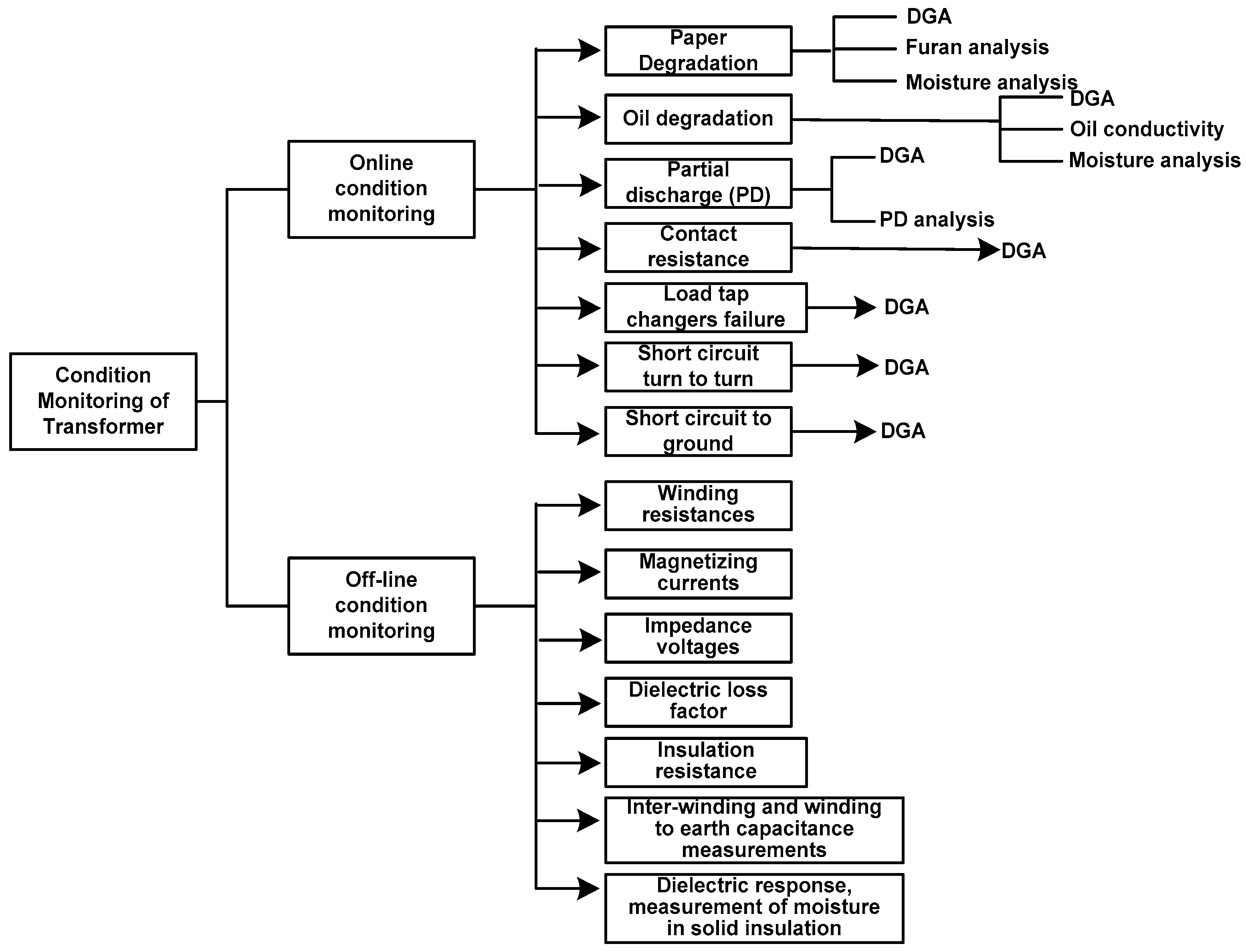
- By monitoring essential operations of the transformer, errors may be identified and removed before their catastrophic failure occurs.
- By changing maintenance, i.e., on request, from the regular to the condition-based service.
- Series line reactors, tuned harmonic filters, and larger pulse number converter circuits like 12-pulse, 18-pulse, and 24-pulse rectifiers can all help to reduce the load’s harmonic current.
- Condition monitoring of transformer should be done from time to time so that if any problem keeps on creating in the transformer, it can be solved in time like harmonics.
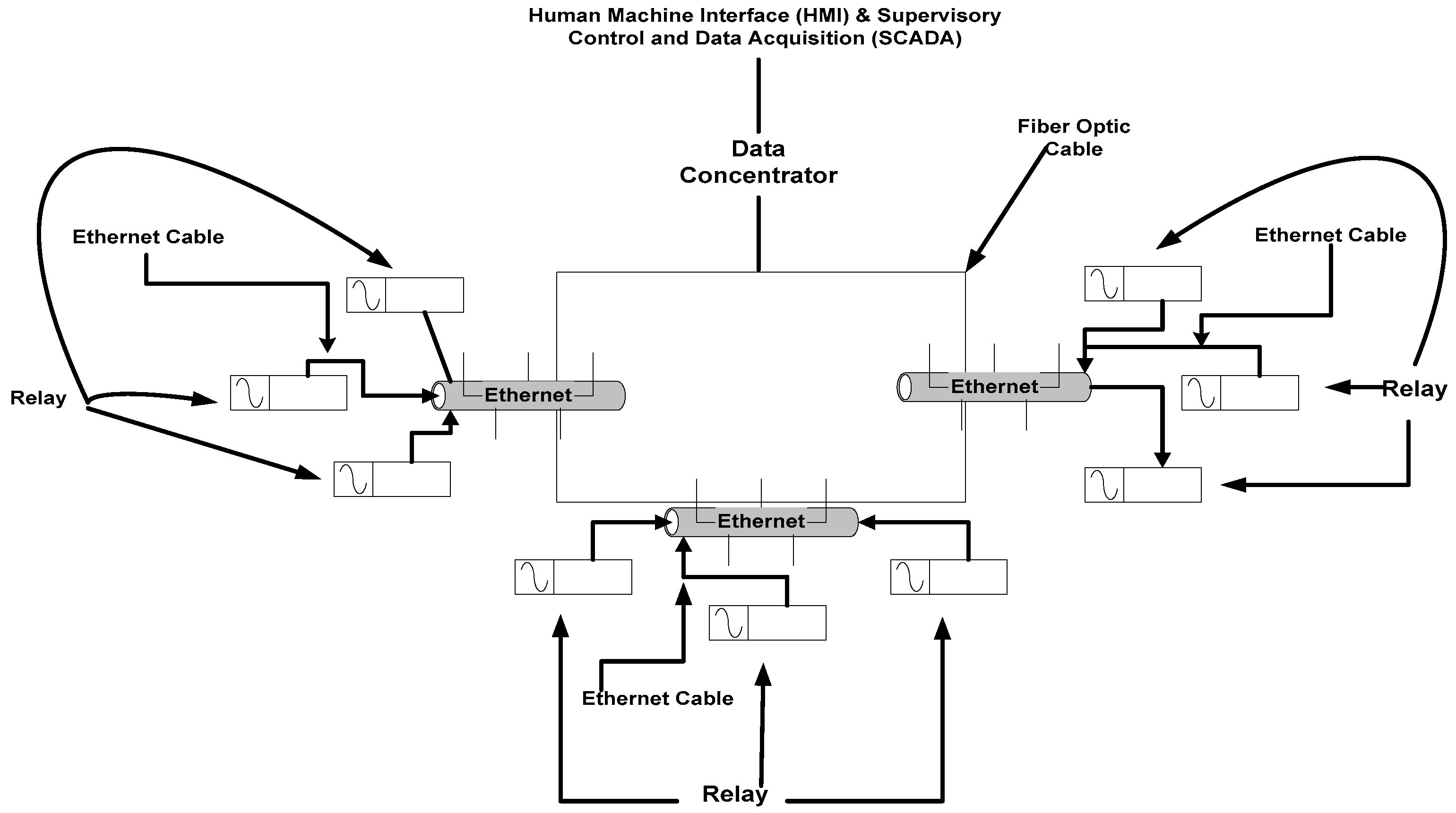
- Install digital substation, these digital substations use IEC-61850 protocol to block harmonics through GOOSE messages. Due to this, if the inrush current is increased in the power transformer, then it has the capability that it can block the harmonics.
- A hardware model is developed to enhance the speed and reliability of backup protection in power transformers.
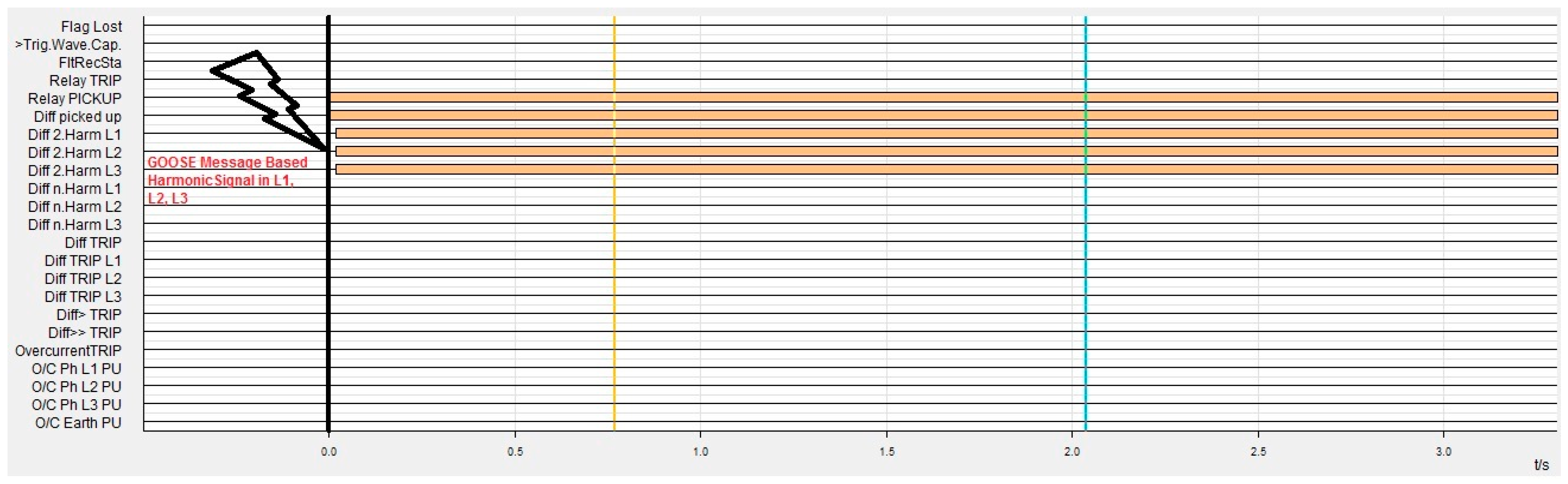
- In this model, IEC 61850 Protocol is employed to communicate between IEDs to block even and odd harmonics (2nd & 5th) in power transformers. The scheme uses GOOSE messaging to send a harmonic blocking signal from the 7UT61 differential IED to the 7SJ64 over-current IED.
- To demonstrate the efficacy of the developed model the harmonic blocking procedure is performed over a range of transformer magnetizing inrush current conditions.
- The interfacing of various equipments of the hardware model for experimental procedure is done by implementing the powerful and efficient operating programs, which include DIGSI4 and Omicron Test Universe 2.11.
2. Overview of IEC 61850
2.1. Method of IEC 61850
- Functional decomposition—to understand the logical relationship between components of a distributed function. They are presented in terms of logical nodes to describe the functions, sub-functions, and functional interfaces.
- Data Flow—helps to understand the communication interfaces supporting the information exchange between distributed functional components and functional performance requirements.
- Information Modelling—defines the abstract syntax and semantics of the information exchanged presented in terms of data object classes, attributes, etc.
2.2. IEC-61850 Communication Protocol Challenges and Limitations
- Very high Costly Equipment
- Issues of time Synchronization between relays and substation
- Lack of availability of trained human personal
- Concern of Existing Infrastructure of substation
2.3. Experimental Demonstration of Even & Odd Harmonic Blocking
- Siemens, Differential Relay, 7UT61
- Siemens, Over-current relay, 7SJ64
- Omicron CMC 256-6 testing kit
- ABB- AFS677, RUGGEDCOM, Ethernet
- DIGSI4, Omicron Test Universe 2.11, IED set-up software
- For testing and monitoring purposes, a personal computer is used
3. Experimental Results Demonstration
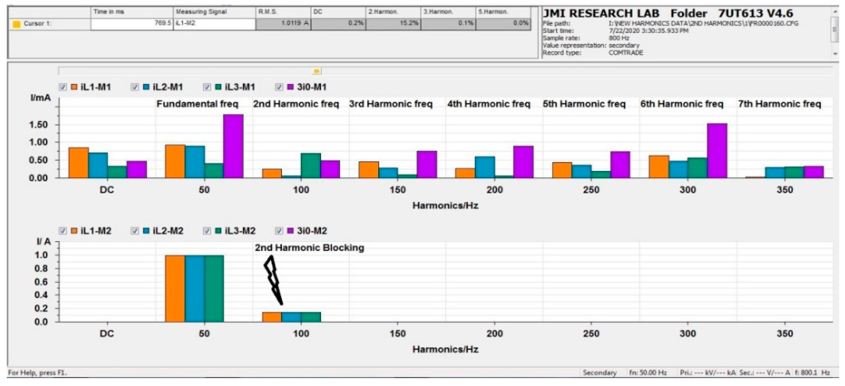
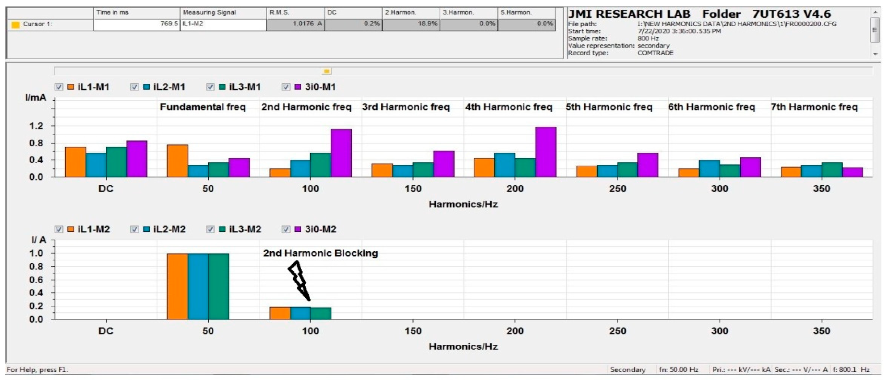
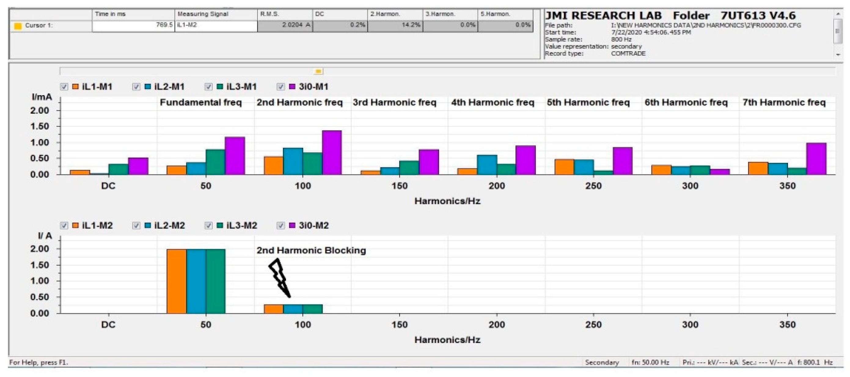
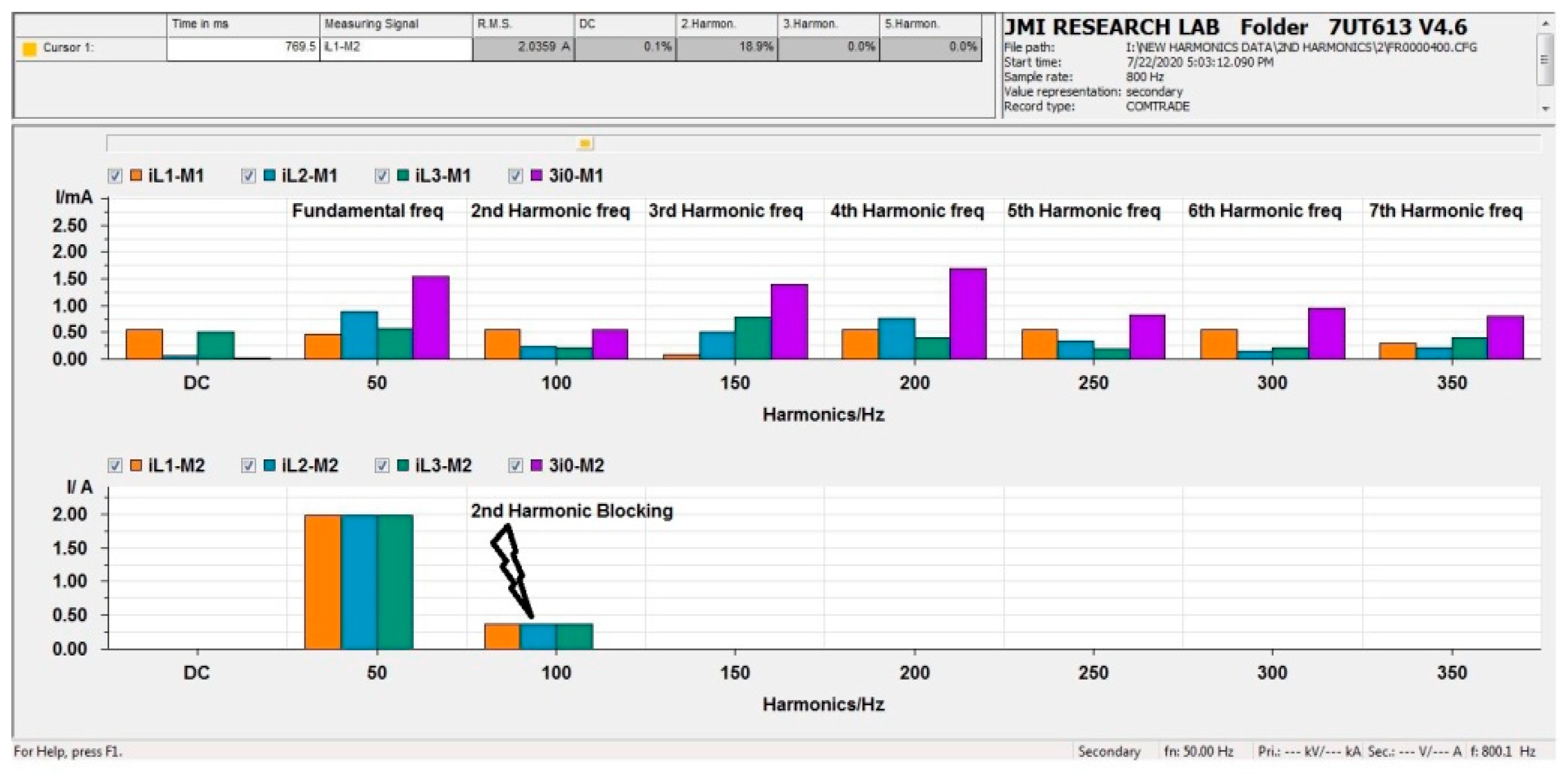
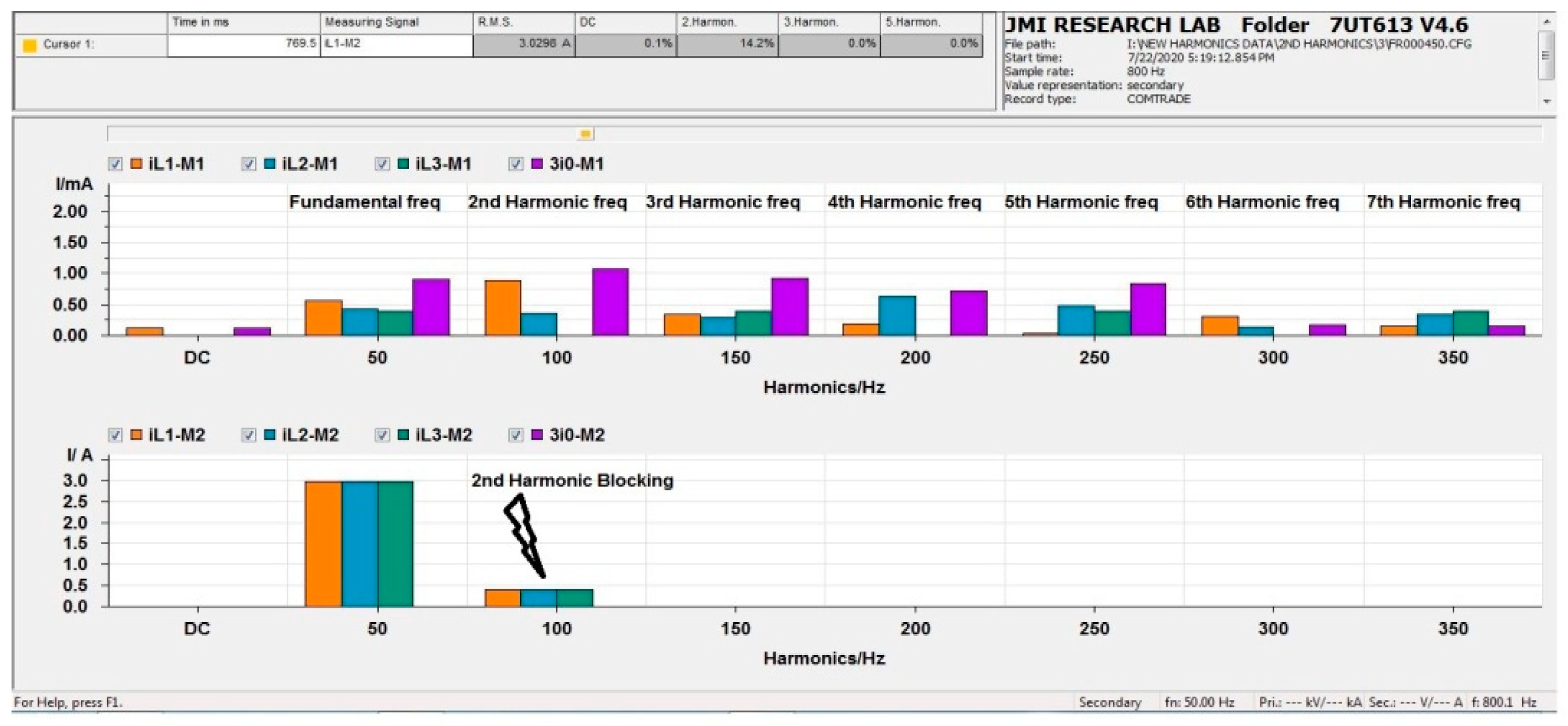
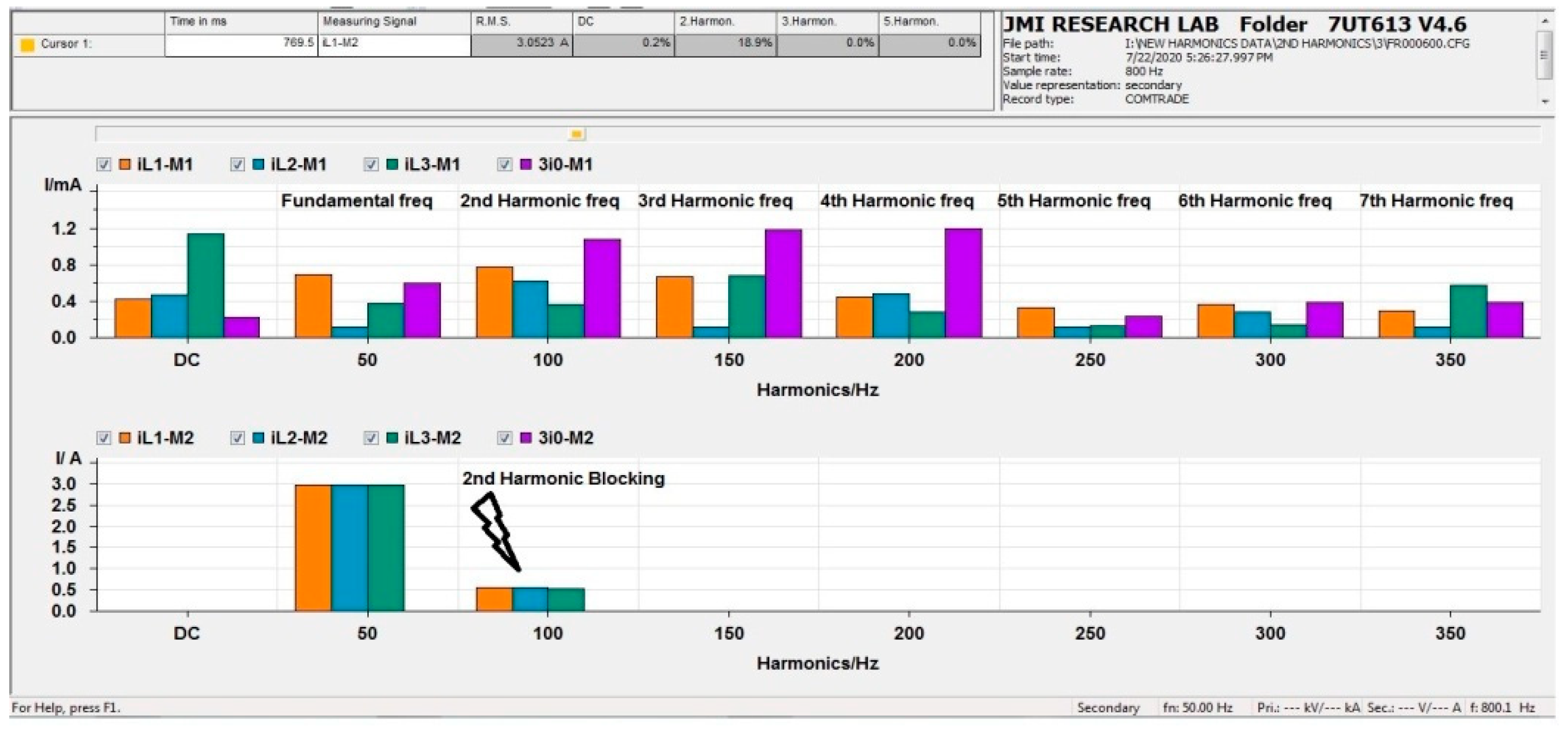
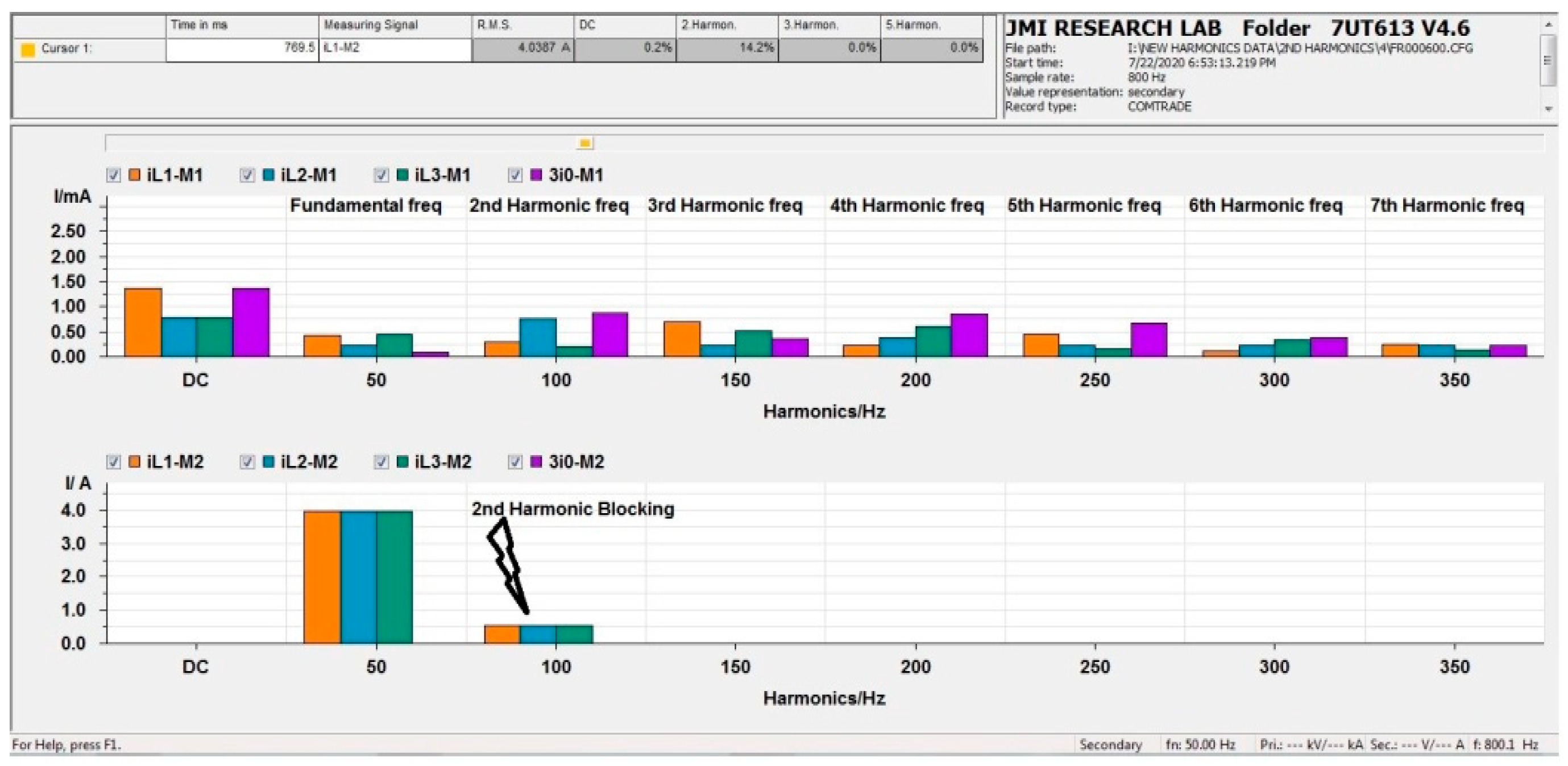
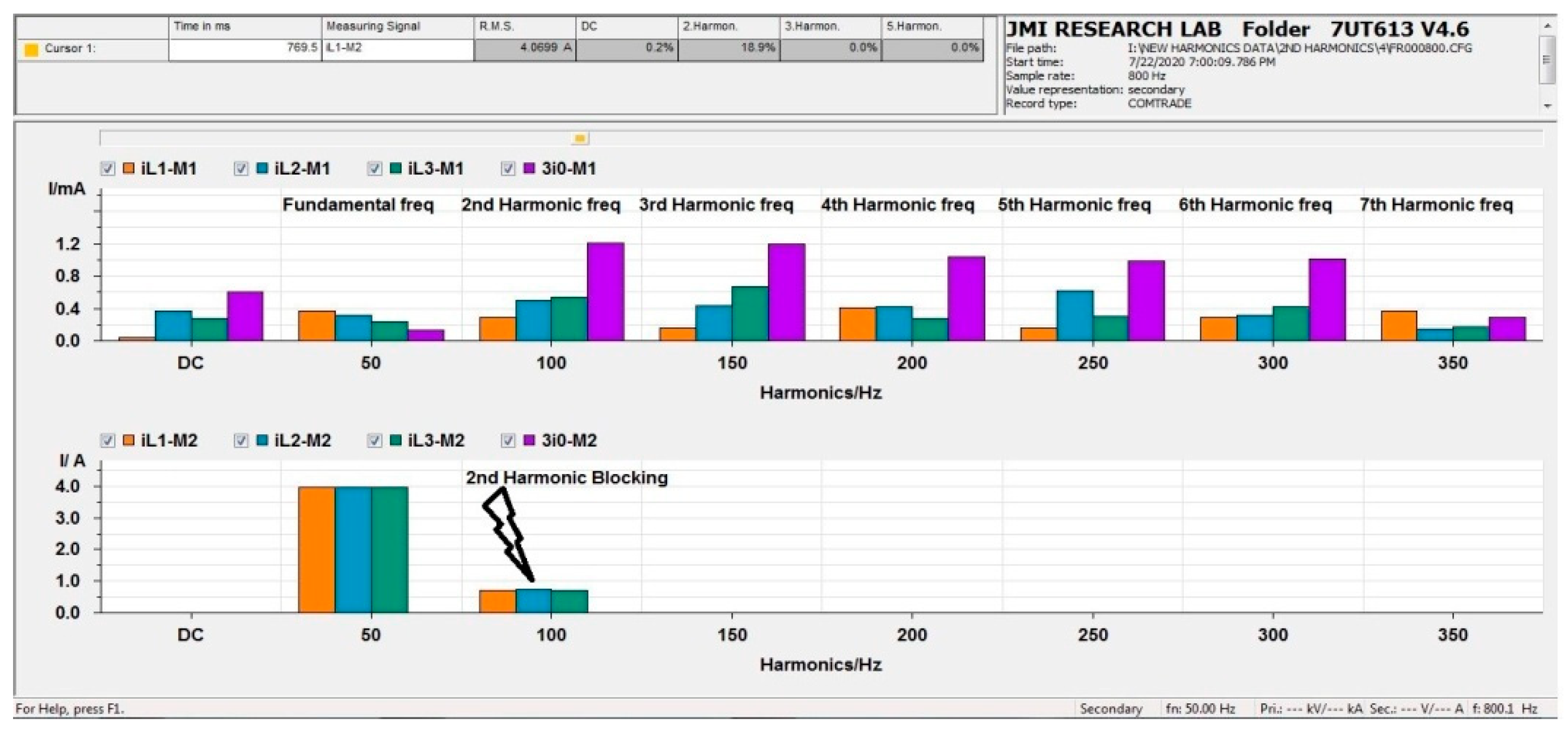
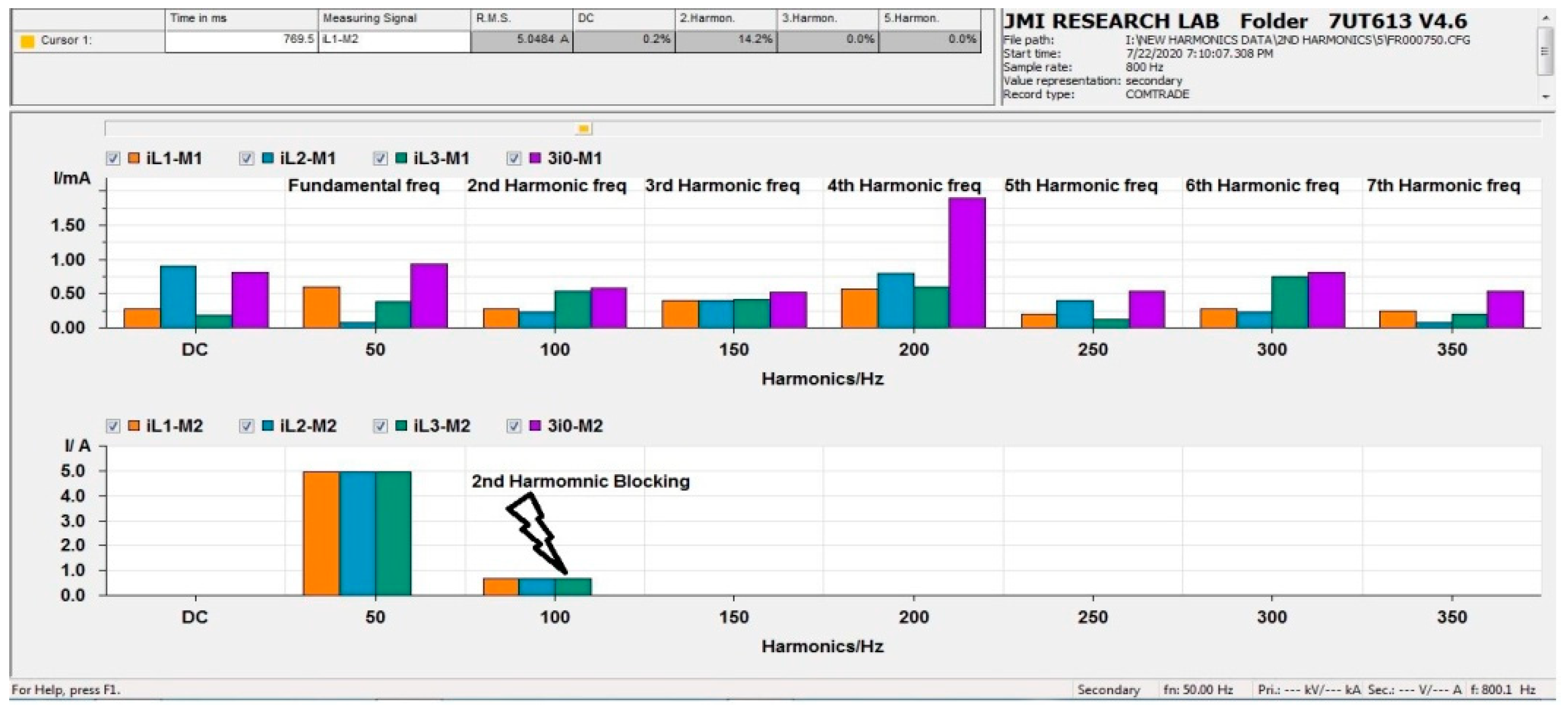
3.1. Experimental Results Demonstration for 2nd Harmonic Diagnosis
- time (ms)
- measuring signal
- RMS value (A)
- DC component (%)
- even/odd-harmonics (%)
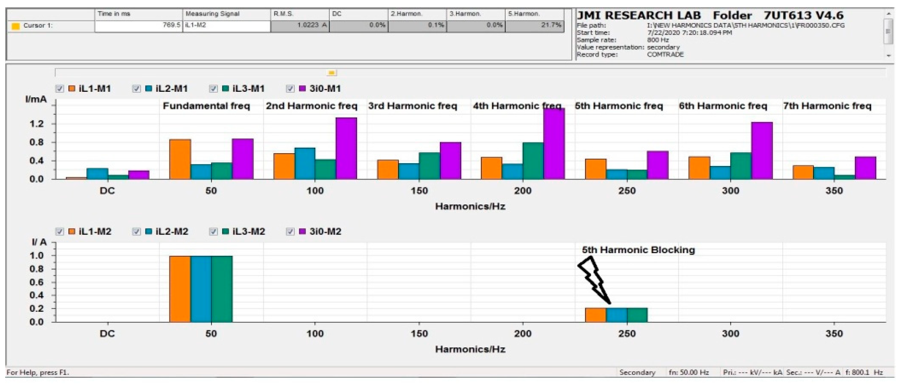
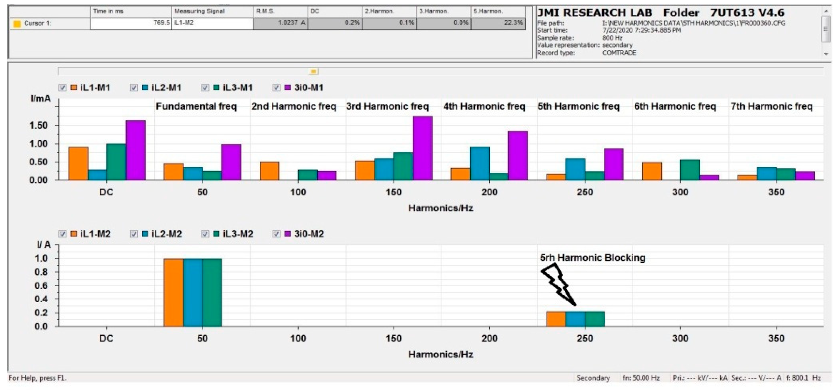
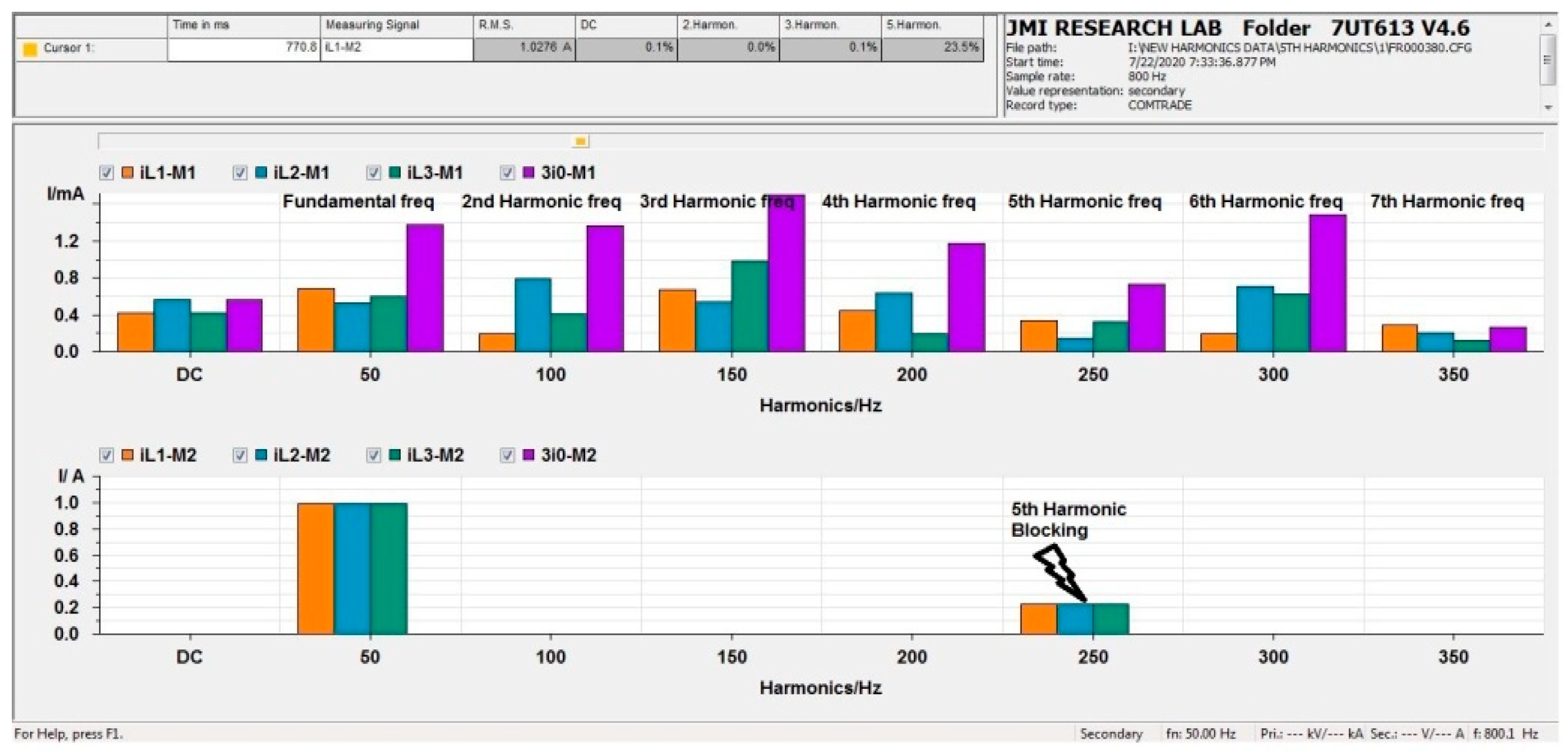
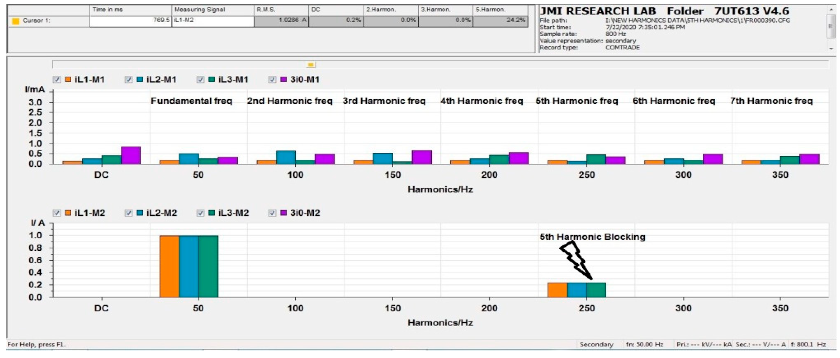
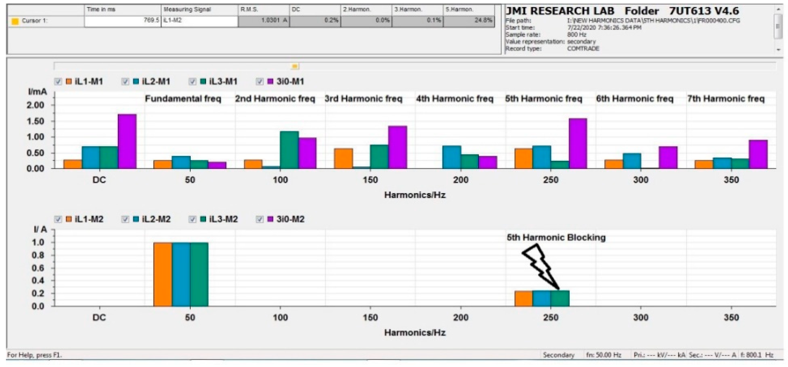
3.2. Experimental Results Demonstration for 5th Harmonic Diagnosis
4. Conclusions and Future Scope
Author Contributions
Funding
Acknowledgments
Conflicts of Interest
Appendix A

| Ref. & Year | Type of Application | Topologies/Analyzed Methods | Main Contribution and Characteristics |
|---|---|---|---|
| [4], (2014) | Electric Power Substation (EPS) | Simulation, Modelling, performance of the network, OPNET Modeler, SCADA | Device Communication between inside and outside the substation, IEC 61850-IEEE 802.3, GOOSE message |
| [5], (2015) | Process bus of IEC-61850 | Kalman filter, True Time software, Matlab Simulink | Communication Sampled Measured Values, delay or loss sampled value, harmonic produced in microprocessor-Based protection technology, noise covariance satisfies the TVE criteria in IEEE C37.118, |
| [6], (2018) | Distance relay, transmission line | field programmable gate arrays (FPGAs), Full-cycle discrete Fourier transform (FCDFT), half-cycle DFT (HCDFT) | phase let-Based distance relaying method, phase & magnitude angle, FPGA provide fast computation speed, Ethernet-Based GOOSE message as per the IEC-61850, HCDFT loss the ability to reject even harmonics, |
| [7], (2017) | Power transmission, Laboratory study | IEC-61850, measurement system | IEC 61850 used in power transmission and improving control and protection, BRICK and transmission system Based on fiber-optic connections through Ethernet, Omicron & CMC 256 used for harmonics, harmonic distribution by using a harmonic module |
| [8], (2018) | Transformer differential relay | Differential protection, IEC 61850 | Physical differential relay under analysis, cover all possible protection problems, developed inside real-time digital simulator, cross & over excitation second and fourth harmonic, blocking, restrained harmonic differential (BHRD)-87HR, harmonic blocking differential (HBD)-87HB, 24HBL—second and fourth harmonic blocking |
| [9], (2019) | Power transformer | IEC-61850, laboratory Test, differential protection | Harmonic block due to transformer magnetizing inrush current, second & fifth harmonic block, installation, and maintenance cost reduced due to IEC-61850, analyzed GOOSE message, |
| [4,24], (2021) | Smart grid, Microgrid, prediction of fault | Fault prediction, different network types, ANN, RNN, Wavelet filter | Investigated fault location in Distribution Network (DN), fast fault recovery, and Wavelet transform have been used for third harmonics fault detection. |
| [25], (2020) | Distributed generators, micro grid | Distributed generator (DG), Micro grid | Conventional and not conventional in a micro grid, IEEE Standard C37.2-2008 for conventional protection scheme, PV array and converter not synchronism & produced harmonics |
| [26], (2019) | Process Bus System | Over sampling (OS), sampling synchronization (SS), GPS time synchronization | The SV’s (sampled value) high-speed publication pace, protection, automation, and control (PAC) applications like security and harmonic monitoring require certain frequency ranges |
| [27], (2020) | Micro Grid | Blackout, On-grid black-start, Off-grid black-start | General guidelines for the established micro grid, Small faults are created in the different micro grid due to harmonics. |
| [28], (2015) | system of multi-fold distribution | Advanced Metering Infrastructure (AMI), Distribution Automation (DA) | Two-way communication through AMI, block harmonic through GOOSE message, Load segment (LS) show THD |
| [29], (2011) | transmission and distribution networks (T & D) | Global Positioning System (GPS), Phasor Measurement Unit, PTP (Precision Time Protocol) | Intelligent Electronics Device (IEDs) play an important role in T & D system, synchronization between IEDs for control & protection of systems, breaker operation within milliseconds & fault detection, combined network of communication network & GPS excellent accuracy, |
| [30], (2020) | Power Transformer protection | Hardware-in-the-loop test, dynamic state estimation | Dynamic state estimation (DSE) Rated approach regular check health status of a transformer, transformer energization due to harmonics, second and fourth harmonic higher when transformer energization, second harmonic block level 20%, |
| [31], (2017) | Smart power grid | SCADA system, MATLAB/Simulink, OMNET++ simulator, Denial of Service (DoS) | IEC-61850 communication protocol implemented, smart grid secure and self-healing and recovery, analyzed and testing of Smart grid (SG) core, network, and components, analyzed harmonics issue in Smart power grid, Electrical Transient Analyzer Program (ETAP) software for analyzed harmonics |
| [32], (2017) | Digital substation process bus | field-programmable gate array (FPGA) | Sampled value of transmission line error electronics transformer, Ethernet communication channel, time offset and time delay in the communication network, different time delay created by the harmonic component |
| [33], (2007) | Overhead lines Protection, transmission line | IEC-61850, arc Modelling, laboratory test | a numerical algorithm for transmission lines protection, fault location in the transmission line, a fast communication channel between two IEDs installed at line terminal, suddenly fault in the transmission line could result in an arc and arc was thought to be a cause of high harmonics. |
| [34], (2015) | Digital Substation | Ethernet, IEC-61850 communication Protocol | Ethernet-Based communication used in the substation of different venders, Real-time data, harmonic block or transformer through differential function, Ethernet integrate between two IEDs, cost-saving to use the IEC-61850 |
| [35], (2016) | Electricity substation | Field Programmable Gate Array (FPGA), Supervisory Control and Data Acquisition (SCADA), VHSIC Hardware Description Language (VHDL) | GOOSE communication network in the substation for monitoring control & protection, IEC 61850 standards cost-effective alternative to parallel copper wiring, reduced overall cost, GOOSE message on FPGA platform, SVs used for transmitting VI (voltage/current) transformer, protection Based on over Ethernet, power system disturbance due to distorted voltage & current signals, transformer heating due to harmonics, generate 2nd & 3rd harmonic, published VI signals during the harmonic disturbance, |
| [36], (2019) | Microgrid | Real-Time Digital Simulator (RTDS), hardware-in-the-loop (HIL), IEC-61850 | Integrate renewable energy source into disturbance network, decentralized adaptive security approach MVAC micro grid, high-speed fault clearing through Hybrid Permissive Overreaching Transfer Trip (HPOTT) and Fast Bus Tripping (FBT), low pass filter removes harmonics |
| [37], (2008) | Power substations | Electrical Power Communication Synchronization Simulator (EPOCHS), Supervisory Control and Data Acquisition (SCADA) | International Electrotechnical Commission (IEC) 61850 and Utility Communication Architecture 2.0 laid the foundation & used in substation, EPOCHS used for run simulation, benefits of utility communication, 48 different simulations configure, power quality of system depends upon the harmonics, |
| [38], (2012) | Electric Substation, transformer | Matlab, IEC-61850, Four Steps Phase Overcurrent Protection (OC4PTOC) | Process bus communication interface with light-weight MU testing environment, Sampled value service from the communication interface, generate 2nd harmonic due to over excitation of the transformer, 2nd harmonic restrain function, 2nd harmonic content of the inrush current, 2nd harmonic introduced with a fault during 20–25 s to test the 2nd harmonic constraint in the OC4PTOC function, OC4PTOC not trip during 20–25 s, trip after 25 s, |
| [39], (2018) | Electrical distribution networks (EDN) with distributed generation (DG) | SCADA, Customer Information System (CIS), Geographic Information System(GIS), Advanced Metering Infrastructure (AMI), Enterprise Asset Management (EAM), | Power quality is an important key to any electrical system. Power quality depends on availability, wave quality, and commercial quality, IEC-61850 GOOSE service used to facilitate adaptive 67/67N protection arrangement, Combining technologies BPLC and IEC 61850 GOOSE service improve recovery times, power quality divided such as sag, wells, transients, harmonics, negative effect on the electrical system, |
| [40], (2015) | Digital Substation Automation System (SAS) | IED Scout, Vamp set configuration tool, Fault analyzer software, ABB PCM 600 IED configuration tool, CMC GOOSE, OPNET, reliability, and probability of failure estimation algorithm (RaFSA) | Issue of IEC-61850 implementation in SAS, different venders & different equipment issues, real-time information available & access through IEC-61850, RaFSA is suitable for analysis & reliability of damaged any device, AC power systems are always in a steady-state and can have flaws like harmonic distortion, sags, and swells, among other things, IEC-61850 standard is used to increase the power quality so that harmonics can generate less |
| [41], (2019) | Smart grid | Virtual Merging Units, IEC 61850, Test Evaluation tool | Power quality, recoding, and protection function is available in IEC-61850, IEC 61850-9-3 allows for time synchronization precision of less than one microsecond, harmonics available or generate in any system to affect the power quality |
| [42], (2015) | FACTS Controllers in IEC 61850, Static VAR Compensator, SVC | SCADA | FACTS devices using in IEC-61850, more logical nodes is required in IEC-61850 for other extensions, the extension of IEC 61850 with Modelling of FACTS, HVDC and Power conversions, Harmonic filters usually passive, those are used to increase voltage stability, filter harmonics, and reduce resonance issues in the system, Shunt connected FACTS devices typically include one or more harmonic filters and control shunt coupled reactor or capacitor branches, ZHAF = Harmonic Filter |
| [43], (2011) | Substation | SCADA, IEC-61850, AutoCad®, CoDeSys, Siemens Step7®, Factory Link® and ISaGRAF®, EnerVistaTM | Software and hardware manufacturers supporting the electric utility sector gathered at Clamart, France, to test their products’ capacity to share data and correctly interpret data Based on the IEC 61850 set of standards. Interoperability in the following areas was the focus of these tests, exchanging configuration information through SCL language, communication services specified by IEC-61850-7-2, 8-1, 9-2LE. Exchange on harmonic information, inrush current increased & energized transformer block 2nd & 5th harmonic. |
| [44], (2015) | Substation Protection and Control | Optical Current and Voltage Sensors, Rogowski Coils as Current Sensor, Intelligent Merging Unit, iSAS, SCADA | Centralized protection and control (CPC), availability of standardized communication technology, advancements in sensor, merging unit, and remote I/O technologies enable the simple gathering of power system data at any place inside a substation, regardless of the location of protection and control equipment. Sending GOOSE message one IEDs to another over the optical fiber Ethernet link. Problems in power quality due to voltage sag, interruption, harmonic, transient. Power quality (PQ) monitoring and investigation conform to international standards IEC 61000-4-30 and IEC 61000-4-7. |
References
- CEA Standing Committee of Experts. Report on Failure of 220 kV & above Voltage Class Substation Equipment. 2016. Available online: http://www.cea.nic.in/reports/committee/failureequipment/failure_dec16.pdf (accessed on 22 October 2021).
- CEA Standing Committee of Experts. Report Failure of 220 kV & above Voltage Class Substation Equipment (January 2017–March 2018). Available online: https://cea.nic.in/old/comm_failure_equip.html (accessed on 21 October 2021).
- Luopajärvi, J. Condition Monitoring of Power Transformer as Part of Power Plant Maintenance Process; University of Vaasa: Vaasa, Finland, 2010. [Google Scholar]
- Nivethan, J.; Papa, M.; Hawrylak, P. Modeling and simulation of electric power substation employing an IEC 61850 network. In Proceedings of the 9th Annual Cyber and Information Security Research Conference, Oak Ridge, TN, USA, 4–8 April 2014; pp. 89–92. [Google Scholar] [CrossRef]
- Abdolkhalig, A.; Zivanovic, R. Simulation and testing of the overcurrent protection system Based on IEC 61850 Process-Buses and dynamic estimator. Sustain. Energy Grids Netw. 2015, 2, 41–50. [Google Scholar] [CrossRef]
- Jin, X.; Gokaraju, R.; Wierckx, R.; Nayak, O. High speed digital distance relaying scheme using FPGA and IEC 61850. IEEE Trans. Smart Grid 2018, 9, 4383–4393. [Google Scholar] [CrossRef]
- Kowalik, R.; Rasolomampionona, D.D.; Januszewski, M. Laboratory testing of process bus equipment and protection functions in accordance with IEC 61850 standard. Part I: Electrical arrangement and basic protection functions tests. Int. J. Electr. Power Energy Syst. 2017, 90, 54–63. [Google Scholar] [CrossRef]
- Magrin, F.; Tavares, M.C. A commercial relay model for the RTDS validated against the actual relay. Electr. Eng. 2016, 100, 167–176. [Google Scholar] [CrossRef]
- Krishnamurthy, S.; Baningobera, B.E. IEC61850 standard-based harmonic blocking scheme for power transformers. Prot. Control Mod. Power Syst. 2019, 4, 10. [Google Scholar] [CrossRef]
- Andersson, L.; Brunner, C.; Engler, F. Substation automation based on IEC 61850 with new process-close technologies. In Proceedings of the 2003 IEEE Bologna PowerTech, Bologna, Italy, 23–26 June 2003; Volume 2. [Google Scholar] [CrossRef]
- Brunner, C.; Kern, T.; Kruimer, B.; Schimmel, G.; Schwarz, K. IEC 61850 Based Digital Communication as Interface to the Primary Equipment—Evaluation of System Architecture and Real Time Behavior; Study Committee B3; CIGRE: Paris, France, 2004. [Google Scholar]
- Tengdin, J.; Simon, M.; Sufana, C. LAN congestion scenario and performance evaluation. In Proceedings of the IEEE Power Engineering Society Winter Meeting, New York, NY, USA, 31 January–4 February 1999. [Google Scholar]
- Tournier, J.-C.; Werner, T. A quantitative evaluation of IEC61850 process bus architectures. In Proceedings of the IEEE PES General Meeting, Minneapolis, MN, USA, 25–29 July 2010; pp. 1–8. [Google Scholar]
- Dolezilek, D. IEC 61850: What You Need to Know About Functionality and Practical Implementation. 2005. Available online: http://www.selinc.com/techpprs/SELDolezilekIEC618506170.pdf (accessed on 30 October 2021).
- Andersson, L.; Brand, K.-P.; Brunner, C.; Wimmer, W. Reliability investigations for SA communication architectures based on IEC 61850. Presented at IEEE PowerTech, Saint Petersburg, Russia, 27–30 June 2005. [Google Scholar]
- Schumach, M. Process Bus Communication in High Voltage Substation Based on IEC 61850; Study Committee B3 Colloquium; CIGRE: Berlin, Germany, 2007. [Google Scholar]
- Mackiewicz, R. Overview of IEC 61850 and Benefits. In Proceedings of the Power Engineering Society General Meeting, Montreal, QC, Canada, 8–22 June 2006; pp. 1–8. [Google Scholar]
- Apostolov, A.; Tholomier, D. Impact of IEC 61850 on power system protection. In Proceedings of the 2006 IEEE PES Power Systems Conference and Exposition, Atlanta, GA, USA, 29 October–1 November 2006; pp. 1053–1058. [Google Scholar]
- Mo, J.; Tan, J.; Crossley, P.; Bo, Z.; Klimek, A. Evaluation of process bus reliability. In Proceedings of the 16th International Conference on Developments in Power System Protection, Manchester, UK, 29 March–1 April 2010; pp. 1–5. [Google Scholar]
- Skendzic, V.; Ender, I.; Zweigle, G. IEC 61850-9-2 Process Bus and its Impact on Power System Protection and Control Reliability; Technical Report; Schweitzer Engineering Laboratories, Inc.: Pullman, WA, USA, 2007. [Google Scholar]
- Brand, K.-P.; Wimmer, W. Investigations of different function allocations in SA Systems enabled by IEC 61850. In Proceedings of the IEEE Lausanne PowerTech Conference, Lausanne, Switzerland, 1–5 July 2007; pp. 720–725. [Google Scholar]
- Midence, R.; Iadonisi, D. Ethernet networks redundancy with focus on IEC 61850 applications. In Proceedings of the 20th International Conference and Exhibition on Electricity Distribution—Part 1, Prague, Czech Republic, 8–11 June 2009; pp. 1–4. [Google Scholar]
- Thomas, M.S.; Ali, I. Reliable, Fast, and Deterministic Substation Communication Network Architecture and its Performance Simulation. IEEE Trans. Power Deliv. 2010, 25, 2364–2370. [Google Scholar] [CrossRef]
- Dashti, R.; DaisY, M.; Mirshekali, H.; Reza, H.; Mahmood, S.; Aliabadi, H. A survey of fault prediction and location methods in electrical energy distribution networks. Measurements 2021, 184, 109947. [Google Scholar] [CrossRef]
- Piesciorovsky, E.C.; Smith, T.; Ollis, T.B. Protection schemes used in North American microgrids. Int. Trans. Electr. Energy Syst. 2020, 30. [Google Scholar] [CrossRef]
- Kazuhiro, K.; Tomida, T.; Itagaki, D.; Okai, M.; Katayanagi, Y.; Iwamaru, A.; Hasegawa, S.; Furusawa, Y. Novel Synchronous Sampling Scheme Based on Oversampling for a Process Bus System. IEEJ Trans. Electr. Electron. Eng. 2019, 14, 716–729. [Google Scholar]
- Cagnano, A.; De Tuglie, E.; Mancarella, P. Microgrids: Overview and guidelines for practical implementations and operation. Appl. Energy 2019, 258, 114039. [Google Scholar] [CrossRef]
- Balakrishna, P.; Rajagopal, K.; Swarup, K.S. Look-ahead distribution power restoration analysis Based on integrated operation of distribution automation and advanced metering infrastructure systems. IET J. Gener. Transm. Distrib. 2015, 9, 2024–2031. [Google Scholar] [CrossRef]
- Carta, A.; Locci, N.; Muscas, C.; Pinna, F.; Sulis, S. GPS and IEEE 1588 synchronization for the measurement of synchro-phasors in electric power systems. Comput. Stand. Interf. 2011, 33, 176–181. [Google Scholar] [CrossRef]
- Fan, R.; Liu, Y.; Meliopoulos, S.; Sun, L.; Tan, Z.; Huang, R. Comparison of transformer legacy protective functions and a dynamic state estimation-based approach. Electr. Power Syst. Res. 2020, 184, 106301. [Google Scholar] [CrossRef]
- Gupta, B.B.; Akhtar, T. A survey on smart power grid: Frameworks, tools, security issues, and solutions. Ann. Telecommun. 2017, 72, 517–549. [Google Scholar] [CrossRef]
- Zhiheng, L.; Xiongying, D.; Liao, M.; Jiyan, Z. A FPGA-Based digital synchronous methodology for IEC 61850-9-2 process bus. AEU Int. J. Electron. Commun. 2017, 76, 137–145. [Google Scholar]
- Radojević, Z.; Terzija, V. Effective Two-terminal Numerical Algorithm for Overhead Lines Protection. Electr. Eng. 2006, 89, 425–432. [Google Scholar] [CrossRef]
- Pal, A.; Dash, R. A Paradigm Shift in Substation Engineering: IEC 61850 Approach. Procedia Technol. 2015, 21, 8–14. [Google Scholar] [CrossRef] [Green Version]
- Ncube, A.M. IEC 61850-9-2 Based Sampled Values and IEC 61850-8-1 Goose Messages Mapping on An FPGA Platform. Ph.D. Thesis, Cape Peninsula University of Technology, Cape Town, South Africa, 2016. [Google Scholar]
- Zaben, M.M.I. Design and Real Time Implementation of an Adaptive Microgrid Protection Strategy. Ph.D. Thesis, King Fahd University of Petroleum & Minerals, Dhahran, Saudi Arabia, 2019. [Google Scholar]
- Roberts, G.R. Evaluating Security and Quality of Service Considerations in Critical Infrastructure Communication Networks. Master’s Thesis, Air Force Institute of Technology, Wright-Patterson AFB, OH, USA, March 2008. [Google Scholar]
- Zhao, P. IEC 61850-9-2 Process Bus Communication Interface for Light Weight Merging Unit Testing Environment. Master’s Thesis, KTH School of Electrical Engineering and Computer Science, Stockholm, Sweden, 2012. [Google Scholar]
- Sánchez, A.S. Automatic Fault Location in Electrical Distribution Networks with Distributed Generation. Ph.D. Thesis, Universitat Politècnica de Catalunya, Electrical Engineering Department, Barcelona, Spain, 2018. [Google Scholar]
- Mekkanen, M. On Reliability and Performance Analyses of IEC 61850 for Digital SAS; Science and Technology: Tripoli, Libya, 2015. [Google Scholar]
- Apostolov, A. Impact of IEC 61850 on power quality monitoring and recording. Presented at CIRED 20th International Conference and Exhibition on Electricity Distribution, Prague, Czech Republic, 8–11 June 2009. [Google Scholar]
- Malmstrom, J. Modelling of FACTS Power System Controller Using IEC 61850; Report TR1706; Malardalen University in Sweden: Vaster, Sweden, 18 January 2015; Available online: http://www.idt.mdh.se/utbildning/exjobb/files/TR1706.pdf (accessed on 20 October 2021).
- Falk, H. Report on the UCA Sponsored 2011 Interoperability Test IEC 61850 Interoperability; 10604 Candler Falls Court, Raleigh, NC27614; UCA International Users Group: Raleigh, NC, USA, 2011. [Google Scholar]
- Das, R.; Kanabar, M. Centralized Substation Protection and Control; WGK 15 Report Centralized Substation Protection and Control; IEEE PES Power System Relaying Committee: Denver, CO, USA, 2015. [Google Scholar]


| Case(s) | Rated Current, Rc (mA) | Injected Inrush Current Condition (%) | Measurement Signal | R.M.S. (A) | DC Component (%) | 2nd Harmonic (%) |
|---|---|---|---|---|---|---|
| I | 1000 | 15 | iL1-M2 | 1.0099 | 0.2 | 14.1 |
| iL2-M2 | 1.0104 | 0.2 | 14.2 | |||
| iL3-M2 | 1.0097 | 0.1 | 14.2 | |||
| 16 | iL1-M2 | 1.0119 | 0.2 | 15.2 | ||
| iL2-M2 | 1.0125 | 0.2 | 15.1 | |||
| iL3-M2 | 1.0112 | 0.1 | 15.1 | |||
| 17 | iL1-M2 | 1.0135 | 0.4 | 16.0 | ||
| iL2-M2 | 1.0133 | 0.3 | 16.1 | |||
| iL3-M2 | 1.0124 | 0.0 | 16.1 | |||
| 18 | iL1-M2 | 1.0145 | 0.5 | 17.0 | ||
| iL2-M2 | 1.0150 | 0.3 | 17.0 | |||
| iL3-M2 | 1.0145 | 0.1 | 17.0 | |||
| 19 | iL1-M2 | 1.0160 | 0.2 | 17.9 | ||
| iL2-M2 | 1.0167 | 0.1 | 17.9 | |||
| iL3-M2 | 1.0159 | 0.0 | 18.1 | |||
| 20 | iL1-M2 | 1.0176 | 0.2 | 18.9 | ||
| iL2-M2 | 1.0183 | 0.1 | 18.9 | |||
| iL3-M2 | 1.0180 | 0.0 | 18.8 | |||
| II | 1500 | 15 | iL1-M2 | 1.5145 | 0.2 | 14.2 |
| iL2-M2 | 1.5160 | 0.1 | 14.2 | |||
| iL3-M2 | 1.5144 | 0.0 | 14.2 | |||
| 16 | iL1-M2 | 1.5163 | 0.1 | 15.1 | ||
| iL2-M2 | 1.5182 | 0.1 | 15.1 | |||
| iL3-M2 | 1.5164 | 0.1 | 15.1 | |||
| 17 | iL1-M2 | 1.5182 | 0.2 | 16.1 | ||
| iL2-M2 | 1.5202 | 0.1 | 16.1 | |||
| iL3-M2 | 1.5186 | 0.0 | 16.1 | |||
| 18 | iL1-M2 | 1.5220 | 0.2 | 17.0 | ||
| iL2-M2 | 1.5224 | 0.1 | 17.0 | |||
| iL3-M2 | 1.5207 | 0.0 | 17.0 | |||
| 19 | iL1-M2 | 1.5238 | 0.1 | 17.9 | ||
| iL2-M2 | 1.5253 | 0.0 | 18.0 | |||
| iL3-M2 | 1.5236 | 0.0 | 18.0 | |||
| 20 | iL1-M2 | 1.5267 | 0.2 | 18.9 | ||
| iL2-M2 | 1.5276 | 0.1 | 18.9 | |||
| iL3-M2 | 1.5256 | 0.0 | 18.9 | |||
| III | 2000 | 15 | iL1-M2 | 2.0204 | 0.2 | 14.2 |
| iL2-M2 | 2.0210 | 0.1 | 14.1 | |||
| iL3-M2 | 2.0186 | 0.0 | 14.2 | |||
| 16 | iL1-M2 | 2.0224 | 0.1 | 15.1 | ||
| iL2-M2 | 2.0235 | 0.1 | 15.2 | |||
| iL3-M2 | 2.0215 | 0.1 | 15.1 | |||
| 17 | iL1-M2 | 2.0247 | 0.2 | 16.0 | ||
| iL2-M2 | 2.0272 | 0.1 | 16.1 | |||
| iL3-M2 | 2.0244 | 0.1 | 16.1 | |||
| 18 | iL1-M2 | 2.0281 | 0.1 | 17.0 | ||
| iL2-M2 | 2.0293 | 0.1 | 17.0 | |||
| iL3-M2 | 2.0277 | 0.0 | 17.0 | |||
| 19 | iL1-M2 | 2.0314 | 0.1 | 18.0 | ||
| iL2-M2 | 2.0331 | 0.1 | 18.0 | |||
| iL3-M2 | 2.0309 | 0.0 | 18. | |||
| 20 | iL1-M2 | 2.0359 | 0.1 | 18.9 | ||
| iL2-M2 | 2.0356 | 0.1 | 18.9 | |||
| iL3-M2 | 2.0336 | 0.1 | 18.9 | |||
| IV | 2500 | 15 | iL1-M2 | 2.5247 | 0.1 | 14.2 |
| iL2-M2 | 2.5257 | 0.1 | 14.2 | |||
| iL3-M2 | 2.5230 | 0.1 | 14.1 | |||
| 16 | iL1-M2 | 2.5278 | 0.2 | 15.1 | ||
| iL2-M2 | 2.5293 | 0.1 | 15.1 | |||
| iL3-M2 | 2.5262 | 0.1 | 15.1 | |||
| 17 | iL1-M2 | 2.5311 | 0.1 | 16.1 | ||
| iL2-M2 | 2.5324 | 0.1 | 16.1 | |||
| iL3-M2 | 2.5301 | 0.1 | 16.1 | |||
| 18 | iL1-M2 | 2.5260 | 0.2 | 17.0 | ||
| iL2-M2 | 2.5367 | 0.1 | 17.0 | |||
| iL3-M2 | 2.5336 | 0.1 | 17.0 | |||
| 19 | iL1-M2 | 2.5401 | 0.1 | 17.9 | ||
| iL2-M2 | 2.5402 | 0.1 | 18.0 | |||
| iL3-M2 | 2.5384 | 0.1 | 18.0 | |||
| 20 | iL1-M2 | 2.5438 | 0.2 | 18.9 | ||
| iL2-M2 | 2.5449 | 0.1 | 18.9 | |||
| iL3-M2 | 2.5424 | 0.1 | 18.9 | |||
| V | 3000 | 15 | iL1-M2 | 3.0298 | 0.1 | 14.2 |
| iL2-M2 | 3.0315 | 0.1 | 14.2 | |||
| iL3-M2 | 3.0271 | 0.0 | 14.2 | |||
| 16 | iL1-M2 | 3.0335 | 0.1 | 15.1 | ||
| iL2-M2 | 3.0344 | 0.1 | 15.1 | |||
| iL3-M2 | 3.0316 | 0.1 | 15.1 | |||
| 17 | iL1-M2 | 3.0381 | 0.2 | 16.1 | ||
| iL2-M2 | 3.0385 | 0.2 | 16.1 | |||
| iL3-M2 | 3.0358 | 0.1 | 16.0 | |||
| 18 | iL1-M2 | 3.0425 | 0.2 | 17.0 | ||
| iL2-M2 | 3.0432 | 0.1 | 17.0 | |||
| iL3-M2 | 3.0399 | 0.1 | 17.0 | |||
| 19 | iL1-M2 | 3.0469 | 0.2 | 17.9 | ||
| iL2-M2 | 3.0484 | 0.1 | 18.0 | |||
| iL3-M2 | 3.0454 | 0.1 | 18.0 | |||
| 20 | iL1-M2 | 3.0523 | 0.2 | 18.9 | ||
| iL2-M2 | 3.0545 | 0.1 | 18.9 | |||
| iL3-M2 | 3.0503 | 0.1 | 18.9 | |||
| VI | 3500 | 15 | iL1-M2 | 3.5352 | 0.1 | 14.2 |
| iL2-M2 | 3.5356 | 0.1 | 14.2 | |||
| iL3-M2 | 3.5312 | 0.1 | 14.2 | |||
| 16 | iL1-M2 | 3.5390 | 0.2 | 15.1 | ||
| iL2-M2 | 3.5408 | 0.1 | 15.1 | |||
| iL3-M2 | 3.5364 | 0.1 | 15.1 | |||
| 17 | iL1-M2 | 3.5433 | 0.1 | 16.1 | ||
| iL2-M2 | 3.5459 | 0.1 | 16.1 | |||
| iL3-M2 | 3.5405 | 0.1 | 16.1 | |||
| 18 | iL1-M2 | 3.5496 | 0.2 | 17.0 | ||
| iL2-M2 | 3.5511 | 0.1 | 17.0 | |||
| iL3-M2 | 3.5470 | 0.1 | 17.0 | |||
| 19 | iL1-M2 | 3.5551 | 0.2 | 17.9 | ||
| iL2-M2 | 3.5563 | 0.1 | 17.9 | |||
| iL3-M2 | 3.5530 | 0.1 | 18.0 | |||
| 20 | iL1-M2 | 3.5614 | 0.2 | 18.9 | ||
| iL2-M2 | 3.5625 | 0.1 | 18.9 | |||
| iL3-M2 | 3.5584 | 0.1 | 18.9 | |||
| VII | 4000 | 15 | iL1-M2 | 4.0387 | 0.2 | 14.2 |
| iL2-M2 | 4.0410 | 0.1 | 14.2 | |||
| iL3-M2 | 4.0365 | 0.1 | 14.2 | |||
| 16 | iL1-M2 | 4.0451 | 0.2 | 15.1 | ||
| iL2-M2 | 4.0459 | 0.1 | 15.1 | |||
| iL3-M2 | 4.0417 | 0.1 | 15.1 | |||
| 17 | iL1-M2 | 4.0501 | 0.2 | 16.1 | ||
| iL2-M2 | 4.0517 | 0.1 | 16.1 | |||
| iL3-M2 | 4.0480 | 0.1 | 16.1 | |||
| 18 | iL1-M2 | 4.0569 | 0.2 | 17.0 | ||
| iL2-M2 | 4.0578 | 0.1 | 17.0 | |||
| iL3-M2 | 4.0540 | 0.1 | 17.0 | |||
| 19 | iL1-M2 | 4.0626 | 0.2 | 17.9 | ||
| iL2-M2 | 4.0638 | 0.1 | 18.0 | |||
| iL3-M2 | 4.0605 | 0.1 | 18.0 | |||
| 20 | iL1-M2 | 4.0699 | 0.2 | 18.9 | ||
| iL2-M2 | 4.0709 | 0.1 | 18.9 | |||
| iL3-M2 | 4.0674 | 0.1 | 18.9 | |||
| VIII | 4500 | 15 | iL1-M2 | 4.5433 | 0.2 | 14.2 |
| iL2-M2 | 4.5459 | 0.1 | 14.2 | |||
| iL3-M2 | 4.5418 | 0.1 | 14.2 | |||
| 16 | iL1-M2 | 4.5496 | 0.2 | 15.1 | ||
| iL2-M2 | 4.5521 | 0.1 | 15.1 | |||
| iL3-M2 | 4.5473 | 0.1 | 15.1 | |||
| 17 | iL1-M2 | 4.5566 | 0.2 | 16.1 | ||
| iL2-M2 | 4.5584 | 0.1 | 16.1 | |||
| iL3-M2 | 4.5538 | 0.1 | 16.1 | |||
| 18 | iL1-M2 | 4.5630 | 0.2 | 17.0 | ||
| iL2-M2 | 4.5653 | 0.1 | 17.0 | |||
| iL3-M2 | 4.5606 | 0.1 | 17.0 | |||
| 19 | iL1-M2 | 4.5708 | 0.2 | 17.9 | ||
| iL2-M2 | 4.5719 | 0.1 | 18.0 | |||
| iL3-M2 | 4.5676 | 0.1 | 17.9 | |||
| 20 | iL1-M2 | 4.5786 | 0.2 | 18.9 | ||
| iL2-M2 | 4.5804 | 0.1 | 18.9 | |||
| iL3-M2 | 4.5754 | 0.1 | 18.9 | |||
| IX | 5000 | 15 | iL1-M2 | 5.0484 | 0.2 | 14.2 |
| iL2-M2 | 5.0508 | 0.1 | 14.2 | |||
| iL3-M2 | 5.0457 | 0.1 | 14.2 | |||
| 16 | iL1-M2 | 5.0555 | 0.2 | 15.1 | ||
| iL2-M2 | 5.0580 | 0.1 | 15.2 | |||
| iL3-M2 | 5.0524 | 0.1 | 15.1 | |||
| 17 | iL1-M2 | 5.0626 | 0.2 | 16.1 | ||
| iL2-M2 | 5.0648 | 0.1 | 16.1 | |||
| iL3-M2 | 5.0601 | 0.1 | 16.1 | |||
| 18 | iL1-M2 | 5.0706 | 0.2 | 17.0 | ||
| iL2-M2 | 5.0728 | 0.1 | 17.0 | |||
| iL3-M2 | 5.0678 | 0.1 | 17.0 | |||
| 19 | iL1-M2 | 5.0788 | 0.2 | 18.0 | ||
| iL2-M2 | 5.0801 | 0.1 | 18.0 | |||
| iL3-M2 | 5.0760 | 0.1 | 17.9 | |||
| 20 | iL1-M2 | 5.0871 | 0.2 | 18.9 | ||
| iL2-M2 | 5.0889 | 0.1 | 18.9 | |||
| iL3-M2 | 5.0848 | 0.1 | 18.9 |
| Rated Current Rc (mA) | Injected Inrush Current Condition (%) | Measurement Signal | R.M.S. (A) | DC Component (%) | 5th Harmonic (%) |
|---|---|---|---|---|---|
| 1000 | 35 | iL1-M2 | 1.0223 | 0.0 | 21.7 |
| iL2-M2 | 1.0242 | 0.0 | 21.8 | ||
| iL3-M2 | 1.0237 | 0.1 | 21.8 | ||
| 36 | iL1-M2 | 1.0237 | 0.2 | 22.3 | |
| iL2-M2 | 1.0265 | 0.1 | 22.5 | ||
| iL3-M2 | 1.0249 | 0.0 | 22.5 | ||
| 37 | iL1-M2 | 1.0260 | 0.1 | 23.0 | |
| iL2-M2 | 1.0274 | 0.1 | 23.1 | ||
| iL3-M2 | 1.0254 | 0.0 | 23.1 | ||
| 38 | iL1-M2 | 1.0276 | 0.1 | 23.5 | |
| iL2-M2 | 1.0287 | 0.0 | 23.7 | ||
| iL3-M2 | 1.0273 | 0.0 | 23.7 | ||
| 39 | iL1-M2 | 1.0286 | 0.2 | 24.2 | |
| iL2-M2 | 1.0301 | 0.1 | 24.4 | ||
| iL3-M2 | 1.0290 | 0.1 | 24.3 | ||
| 40 | iL1-M2 | 1.0301 | 0.2 | 24.8 | |
| iL2-M2 | 1.0321 | 0.0 | 25.0 | ||
| iL3-M2 | 1.0303 | 0.0 | 25.0 |
Publisher’s Note: MDPI stays neutral with regard to jurisdictional claims in published maps and institutional affiliations. |
© 2021 by the authors. Licensee MDPI, Basel, Switzerland. This article is an open access article distributed under the terms and conditions of the Creative Commons Attribution (CC BY) license (https://creativecommons.org/licenses/by/4.0/).
Share and Cite
Azeem, A.; Jamil, M.; Qamar, S.; Malik, H.; Thokar, R.A. Design of Hardware Setup Based on IEC 61850 Communication Protocol for Detection & Blocking of Harmonics in Power Transformer. Energies 2021, 14, 8284. https://doi.org/10.3390/en14248284
Azeem A, Jamil M, Qamar S, Malik H, Thokar RA. Design of Hardware Setup Based on IEC 61850 Communication Protocol for Detection & Blocking of Harmonics in Power Transformer. Energies. 2021; 14(24):8284. https://doi.org/10.3390/en14248284
Chicago/Turabian StyleAzeem, Abdul, Majid Jamil, Shamimul Qamar, Hasmat Malik, and Rayees Ahmad Thokar. 2021. "Design of Hardware Setup Based on IEC 61850 Communication Protocol for Detection & Blocking of Harmonics in Power Transformer" Energies 14, no. 24: 8284. https://doi.org/10.3390/en14248284
APA StyleAzeem, A., Jamil, M., Qamar, S., Malik, H., & Thokar, R. A. (2021). Design of Hardware Setup Based on IEC 61850 Communication Protocol for Detection & Blocking of Harmonics in Power Transformer. Energies, 14(24), 8284. https://doi.org/10.3390/en14248284