Article

BiFeO3 Coupled Polysulfide Trapping in C/S Composite Cathode Material for Li-S Batteries as Large Efficiency and High Rate Performance

1
Department of Physics, University of Puerto Rico, San Juan, PR 00936, USA
2
Department of Physics, S. S. Jain Subodh P.G. (Autonomous) College, Jaipur 302004, India
3
Department of Physics, Indian Institute of Technology, Jodhpur 342037, India
*
Authors to whom correspondence should be addressed.
Energies 2021, 14(24), 8362; https://doi.org/10.3390/en14248362
Submission received: 19 November 2021 / Revised: 6 December 2021 / Accepted: 7 December 2021 / Published: 11 December 2021

Abstract

:
We demonstrated the efficient coupling of BiFeO3 (BFO) ferroelectric material within the carbon–sulfur (C-S) composite cathode, where polysulfides are trapped in BFO mesh, reducing the polysulfide shuttle impact, and thus resulting in an improved cyclic performance and an increase in capacity in Li-S batteries. Here, the built-in internal field due to BFO enhances polysulfide trapping. The observation of a difference in the diffusion behavior of polysulfides in BFO-coupled composites suggests more efficient trapping in BFO-modified C-S electrodes compared to pristine C-S composite cathodes. The X-ray diffraction results of BFO–C-S composite cathodes show an orthorhombic structure, while Raman spectra substantiate efficient coupling of BFO in C-S composites, in agreement with SEM images, showing the interconnected network of submicron-size sulfur composites. Two plateaus were observed at 1.75 V and 2.1 V in the charge/discharge characteristics of BFO–C-S composite cathodes. The observed capacity of ~1600 mAh g−1 in a 1.5–2.5 V operating window for BFO30-C10-S60 composite cathodes, and the high cyclic stability substantiate the superior performance of the designed cathode materials due to the efficient reduction in the polysulfide shuttle effect in these composite cathodes.

1. Introduction

The lithium–sulfur (Li–S) battery is presently attracting attention among high-energy storage devices because of its relatively large theoretical specific capacity (1675 mAh/g), and its environmental-friendliness in conjunction with its relatively low cost [1]. However, the usage of Li-S batteries also results in various issues being encountered, such as fast capacity reduction, less use of active material, short lifespan, and poor Columbic efficiency because of sulfur’s insulating nature and the polysulfide shuttle effect, as well as large fluctuations during charge/discharge cycles [2]. The intermediate lithium polysulfides produced during the reaction are soluble in the currently used liquid electrolytes, causing a reduction in efficiency, and thus resulting in poor cathode materials. In the present study, the schematic of Li-S battery is shown in Figure 1a, with all of its different components in discharging (Load) and charging (Electric plug) conditions with respective lithium ion dynamics. Additionally, the charging and discharging conditions, together with LixSy clusters, are shown in Figure 1b. Here, two plateaus are shown, and higher sulfur content complexes correspond to a higher plateau, whereas lower sulfur complexes correspond to lower plateau regions. However, shuttle effects caused by polysulfides in the C-S composites hamper the real potential of Li-S batteries and result in capacity fading (Figure 1b). The nanostructuring of materials of less than or equal to 100 nm may increase the surface-to-volume ratio, and thus increase the cathode capacity together with enhanced rates. Even with the nanostructuring of cathode materials, there are still challenges in Li-S batteries, especially the dissolution of lithium polysulfides (Li2Sn, 4 < n < 8) during the initial cycles. These dissolved polysulfides may be further lithiated to lower-order polysulfides (Li2Sn 1 < n < 4), resulting in insulating lithium sulfide (Li2S) on the lithium metal surface during the diffusion of lithium [3]. Further, some polysulfides are oxidized to higher-order polysulfides during the subsequent charging cycles and return to the sulfur cathode by an electric field, exhibiting the shuttling process, which results in self-discharge causing unstable interfaces at both cathode and anode electrodes, thus resulting in the loss of the sulfur cathode’s active material [4]. This study provides an innovative way of overcoming barriers by introducing ferroelectric materials in composites. The ferroelectric domain provides an intrinsic internal field, trapping heteropolar LixSy clusters, and thus enhancing the electrochemical performance of Li-S batteries. This approach is straightforward and cost-effective in achieving a performance near to theoretical values.
Thus, it becomes essential to eliminate or at least minimize the polysulfide shuttle effect for enhanced electrochemical performance. There are various reports on reducing this; for example, Nazar et al. showed a new pathway to confine the polysulfides within porous and conductive carbon materials [5]. Li et al. reported the usefulness of superparamagnetic iron oxide nanoparticles in mitigating the shuttle effect by using a magnetic field [6]. Arava et al. introduced a new concept of electrocatalysis in Li-S batteries to stabilize the polysulfide shuttling issues via a high-electrocatalysis active Pt/graphene host [7]. Ferroelectric materials have attracted much attention because of the intrinsic polarization field, which may assist in capturing polysulfides, thus reducing the shuttling impact on electrochemical performance. The spontaneous polarization in ferroelectric materials gives rise to the internal electric field. The heteropolar nature of polysulfides can assist in their being trapped on the surface of ferroelectric materials because of spontaneous polarization, thus resolving the shuttle effect to some extent. Considering this, we investigated BiFeO3 (BFO) ferroelectric material by integrating it into the C-S cathode material and demonstrated, for the first time, that it stabilizes Li-S batteries by trapping the polysulfides. Here, BFO nanoparticles act as the trapping centers for polysulfides in the integrated C-S composite cathode material. The electric-field-mediated spontaneous polarization is the main source for trapping charged polysulfides. The BFO is used as an additive by directly mixing with C–S composites. The detailed structural, microstructural, vibrational, electrical polarization, and electrochemical measurements are carried out to understand the structural evolution of BFO–C-S composite cathode material and its impact on the materials’ characteristics. Further, the charge/discharge measurements are carried out to understand the impact of BFO additives in C-S composite cathode materials on the enhanced specific capacity and stability of the investigated cathode material.

2. Materials and Methods

2.1. Synthesis of BFO Nanoparticles

The synthesis of BFO (BiFeO3) nanoparticles was carried out using bismuth nitrate and iron nitrates, water and HNO3 acid. The materials were mixed in the stoichiometric ratio and heated at 80–90 °C to form a gel (about 4–5 h). This gel was further heated at 180 °C for 2 h in an oven. The synthesized BFO nanoparticles were collected and finally heated at 550 °C for 10 h.

2.2. Synthesis of BFO–S-C Composite Cathode

We used a simple ball-milling process, for large-scale production of BFO–C-Sulfur composite cathode material [8]. Further, the slurries of BFO–C-Sulfur (BFOxS1-xC where x = 0.10, 0.20, 0.30 wt%) were prepared by mixing polyvinylidene fluoride (PVDF) (5 wt%), in N-methylpyrrolidone (NMP) at 400 rpm for 12 h. The average mass of active material was 1.54 × 10⁻⁵ kg. The slurry was applied to aluminum foil and dried at 80 °C in a vacuum oven for 12 h. Here, aluminium also acted as the current collector. The dried composite films were punched into 11 mm electrodes and transferred into an argon-filled glove box for the assembly of the coin-cells. The coin-cells were assembled using these BFO–C-Sulfur composite electrodes as the cathode, a piece of lithium foil (13 mm in diameter) as the anode, polypropylene (25 μm thickness) as the separator and an organic electrolyte, i.e., 1 M LiPF6 in tetra ethylene glycol dimethyl ether (TEGDME), which is considered the most efficient electrolyte for Li-S batteries. The cathode, separator, and anode were pressed by a crimping machine to ensure tight contact between electrodes and the current collectors. The coin-cells’ charge/discharge characteristics were investigated using a SOLATRON ANALYTICAL battery tester at 0.5 mA constant current in an operating window rated between 1.3 and 2.9 V. The specific capacity was computed using the active BFO–C–Sulfur composite cathode material mass using the charge/discharge data.

2.3. Material Characterization and Electrochemical Measurements

X-ray diffraction (XRD) measurements were performed using the Rigaku-3 system (40 KV, 44 mA) with Cu-Kα incident radiation, having λ = 1.4028 A0, within 2Ɵ = 5°–85° at 1°/min scan rate. The powder X-ray diffraction software, equipped with the Rigaku system, was used to analyze the crystallographic nature of the BFO–C-S composite cathode material. The Raman spectra were recorded using an Ar LASER at a 514.5 nm excitation wavelength. The laser spot size on the sample was <3 µm in diameter and beam intensity was kept at 2.15 mW. All the spectra for BFO–C-S composite cathode materials were recorded at room temperature. The SEM (JEOL 6480LV) system is used for collecting the surface topography of synthesized BFO–C-S composite cathode materials. An eight-channel SOLATRON analytical battery tester was used to collect charging/discharging characteristics in Li-S coin-cell geometries.

3. Results and Discussion

3.1. X-ray Diffraction and Raman Spectra

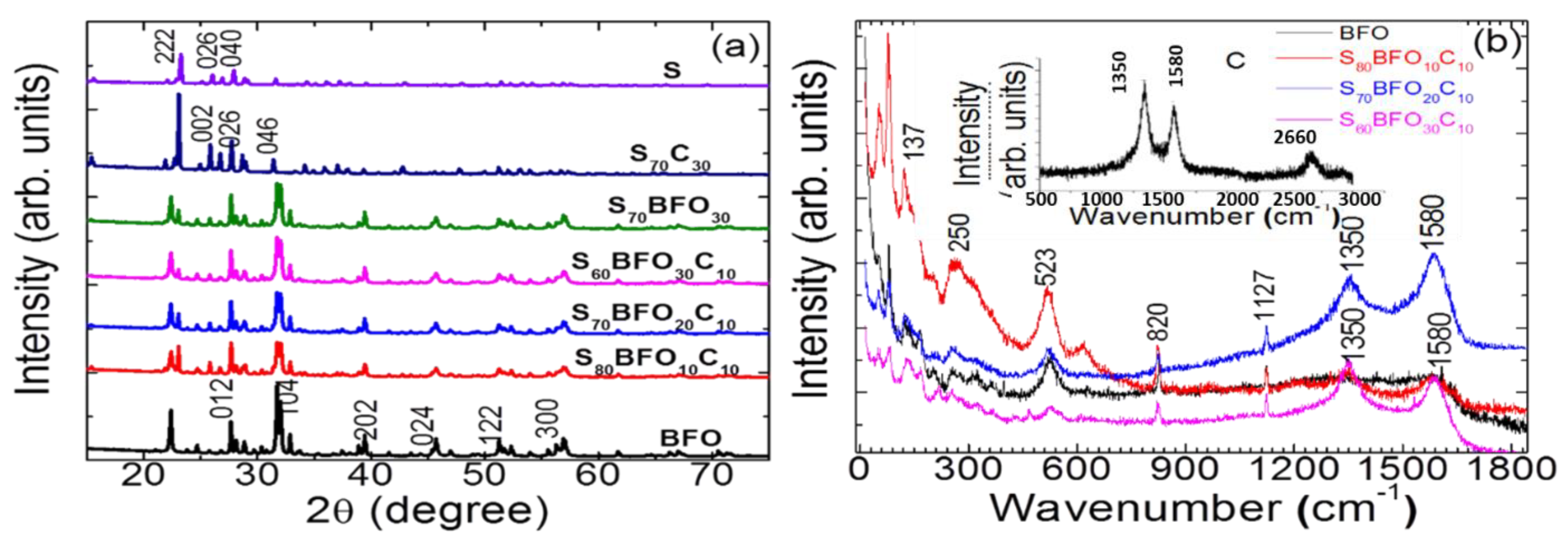
The X-ray diffraction (XRD) spectra for synthesized BFO–C–S composite cathode materials are shown in Figure 2a for different BFO weight fractions and compared to their respective pristine components, sulfur, and BFO. The ICCD data are shown in the bottom panel of Figure 2a for both orthorhombic sulfur and rhombohedral bismuth ferrite for reference. The diffraction peaks at 23.1°, 25.9°, and 27.8° in these XRD patterns correspond to (222), (026), and (040) planes, respectively, for orthorhombic sulfur (ICDD # 832283) and are consistent with the reported literature [9]. The S60BFO30C10 composite cathode material shows all the sulfur diffraction peaks, together with an extra peak at 25.60, showing the carbon (002) diffraction peak together with BFO diffraction peaks, consistent with ICDD # 861518. However, variation in the intensity of peaks indicates the lack of long-range order due to sulfur confinement into carbon and BFO. The size of sulfur particles is ~10–15 µm, and that of carbon is 50–60 nm, as estimated from the Scherrer formula [10,11]. Interestingly, a large reduction in graphitic carbon diffraction peak intensity is observed, together with a downward shift of the (002) diffraction peak with sulfur content. This is attributed to the high degree of exfoliation of carbon during the ball-milling process. As expected, the BFO–C-Sulfur (S60C10) composite material also produced the same diffraction pattern, confirming the similar crystalline features for the sulfur in the composite samples. The XRD patterns of pristine sulfur and BiFeO3 nanoparticles were used for comparison with other BFO–C-S composite cathode materials (Figure 2a).
The vibrational features of BFO–C-Sulfur composite cathode materials were investigated using room-temperature Raman spectroscopic measurements, and the collected Raman spectra are summarized in Figure 2b. For comparison, the Raman spectrum of pristine BFO is also shown in Figure 2b in a black color, together with an inset showing the Raman spectrum for pristine carbon material for comparison. The factor group analysis for BiFeO3 at point, i.e., 4A1 + 5A2 + 9E, suggests a total of 18 optical phonon modes. Among these, the four A1 and nine E modes are both Raman and infrared active modes, and five A2 vibrational modes are both Raman and infrared inactive modes. The low wavenumber peaks noticed at 140, 175, 220, and 430 correspond to A1(LO) phonon modes, whereas vibrational peaks noticed at 75, 260, 275, 310, 350, 370, 470, and 520 cm−1 correspond to E(TO) modes for the BiFeO3 system. The observation of these modes substantiates the phase purity of BiFeO3 nanoparticles’ rhombohedral R3c structure. These are in agreement with the previous reports [12]. The characteristic carbon peaks are identified at 1350 and 1580 cm−1, which correspond to D and G characteristic bands (inset Figure 2b) [13]. These characteristic carbon vibration modes are observed in all BFO–C-S composite samples (Figure 2b), suggesting the efficient integration of carbon into the BFO–C-S composite matrix. Further, three rhombic sulfur characteristic peaks are observed at ~137, 250, and 523 cm−1 in all BFO–C-S cathode materials, implying the efficient impregnation of sulfur with carbon in these composite cathode samples.

3.2. SEM Analysis

SEM images (Figure 3a–e) are for pristine BiFeO3 (BFO) and carbon (C) samples, S80BFO10C10, and S60BFO30C10 composite cathode samples, together with the EDX elemental composition analysis graph for the S60BFO30C10 composite cathode sample, respectively. The pristine BFO sample (Figure 3a) depicts the hollow nano-spherical morphology with a diameter less than 80 nm, while Figure 3c,d show a unique network in composite cathode materials, consisting of interconnected submicron-sized macropores because of embedded BFO and carbon nanoparticles in the sulfur host matrix. The material surrounding the sulfur matrix is acting as a protective layer, showing the morphology of S80BFO10C10 and S60 BFO30C10 composite materials in Figure 3c,d, respectively. The enhancement surface area is notable due to its structural features, which provide more defect sites at which lithium ions may be adsorbed to the surface of loosely bound carbon layers [14,15,16]. This network structure for composite samples also confirms the close contact between BFO, carbon, and sulfur, which is useful in avoiding the loss of soluble polysulfides in electrolytes.

3.3. Ferroelectric (P–E) Polarization and Magnetic Hysteresis

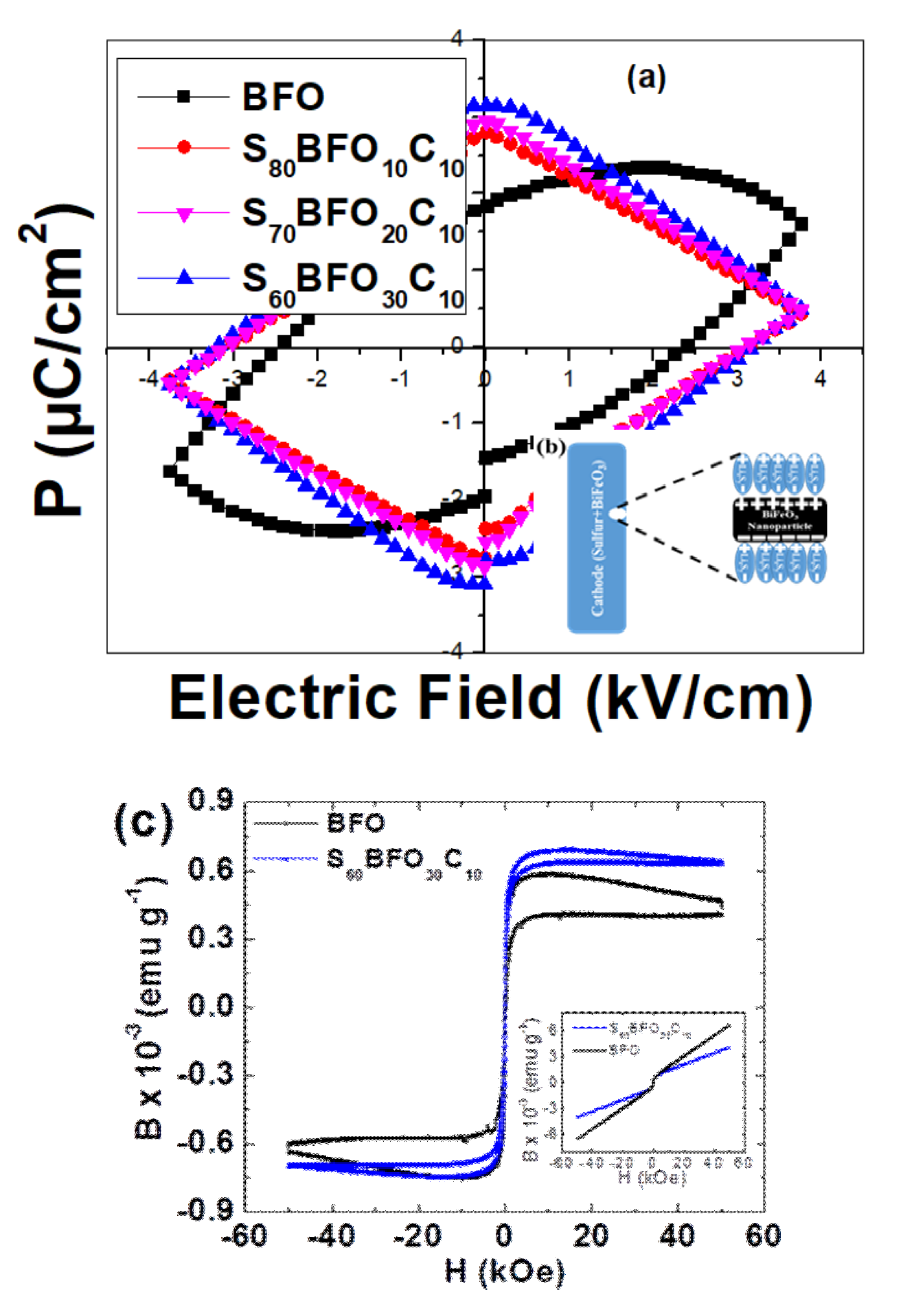
Spontaneous polarization is the key for polysulfide trapping. We carried out ferroelectric measurements using the P–E hysteresis loop measurement system on these BFO–C-Sulfur composites at 5 kV bias voltage and 1 kHz frequency. The measured ferroelectric P-E hysteresis loops are shown in Figure 4a for S60BFO30C10, S70BFO20C10, and S80BFO10C10 composite cathode materials. All these composites show well-defined ferroelectric characteristics, together with ferroelectric characteristics, for pristine BFO material. However, the remanent polarization (Pr) for BFO at 1 kV/cm is 2.5 µC/cm2, and is less than the reported values in BiFeO3 (BFO) thin films but higher than that observed in bulk BiFeO3 powder samples [17,18,19]. The largest induced polarization for S60BFO30C10 material is ~3.2 µC/cm2. This variation in polarization hysteresis may be correlated with the formation of vacancies due to the inclusion of BFO and carbon, resulting in enhanced conductivity and structural distortion to induce ferroelectricity in composites. Thus, the inclusion of BFO in the C-S composite cathode materials will induce polarization, which may assist as the key ingredient for trapping polysulfide formation during the charging and discharging of Li-S batteries. This is schematically explained in Figure 4b. In addition, the magnetic hysteresis measurements are also carried out on BFO and S60BFO30C10 powder samples (Figure 4c). As shown in the inset in Figure 4c, the unprocessed data show a large paramagnetic contribution in higher fields. This paramagnetic background is subtracted to obtain the magnetization values for these samples. These samples show non-zero magnetization; however, the value of magnetization is very small. This is attributed to the spin canting in BFO samples. Additionally, the nanoparticles of BFO may also introduce some unsaturated spin, contributing to the small magnetic moment, as noticed in the present case (Figure 4c). More interestingly, a nearly similar magnetic moment is observed in the optimal composite sample (i.e., S60BFO30C10) with the largest ferroelectric polarization. This non-zero magnetic moment will contribute to the non-zero internal field, thus inducing a non-zero Lorentz force (F = q v × B) on charged polysulfide ions. This force is determined to alter the path of such dissolved charged polysulfide ions, thus enhancing electrochemical performance by promoting the trapping of these polysulfide ions.

3.4. Electrochemical Performance

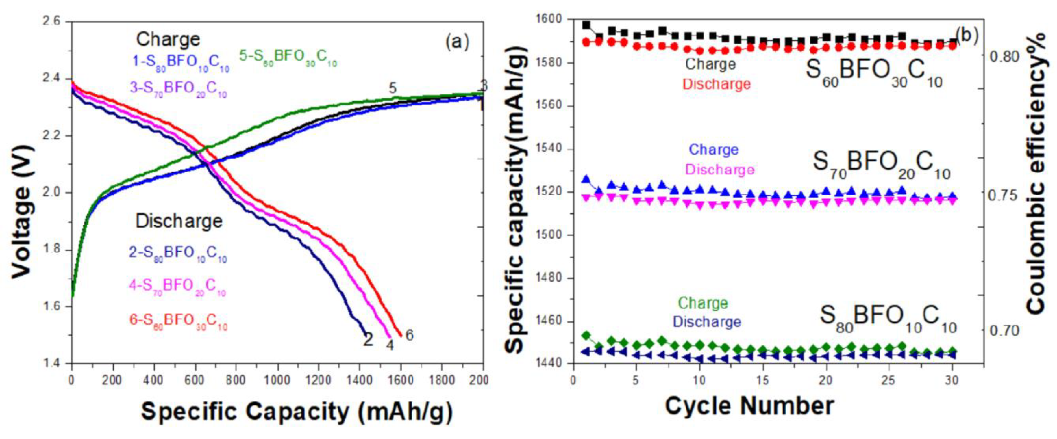
The charge/discharge capacity versus voltage profiles are shown in Figure 5a for different BFO–C-Sulfur composite cathode materials. The charge/discharge measurements were carried out at a C/5 rate using 1 M LiPF6 electrolyte in TEGDME solvent. The charge/discharge profiles exhibit two main plateaus, originating from the sulfur’s electrochemical reactions [14]. The soluble polysulfides are firstly formed in a 2.4–2.2 V range, whereas the solid reduction products are formed in the second window 2.1–19 V on the conductive carbon matrix. [20,21,22]. The composite of S60C35 shows a stable and high energy capacity of 1576 mAh/g when cycled between 2 V and 4.9 V during deep discharge [8]. We noticed that, after the first cycle, the plateau 2.38 V (vs. Li+/Li) disappeared. In the charging process, a long plateau is observed, which is attributed to the conversion of Li2S into higher-order soluble polysulfide.
The BFO–C-Sulfur composite cathode exhibits a much higher initial discharge capacity of approximately 1640 mAh/g at C/5 and, after 30 cycles, a reversible similar discharge capacity can still be retained with a stable rate, indicating the long-term cycling stability of these cathode materials. We observed that 1280 mAh/g can be obtained even after 30 cycles for the C-Sulfur composite cathode material without BFO, indicating that integrating spontaneously polarized BFO particles in the cathode materials can significantly improve the cycle stability of C-Sulfur composite cathode materials. The coupling of ferroelectric BFO particles enhances the trapping of LixSy clusters, thus reducing the shuttle effect. We attribute this reduction in the shuttle effect as the main source of the observed capacity of Li-S batteries in the present study. The cycling performance is shown in Figure 5b for BFO–C-Sulfur composite cathode materials with different BFO weight fractions, indicating the stable specific capacity ~1640 mAh/g–1600 mAh/g for S60BFO30C10, ~1525 mAh/g–1520 mAh/g for S70BFO20C10, and ~1450 mAh/g–1440 mAh/g for S80BFO10C10 composite cathode materials for up to 30 cycles, confirming the efficient trapping of polysulfide formation by coupling BFO in the C-S matrix. The Coulombic efficiency (CE) is ~62% for the S80%BFO10%C10% composite, whereas there is ~86% Coulombic efficiency for the cell that has S60%BFO30%C10% composite material. This may be due to the trapping of parasitic side reactions occurring between S and Li with ferroelectric (BiFeO3) coupling.
Further, the impact of the C-rate on discharge capacity is summarized in Figure 6a for these cathode materials. We observed a much higher discharge capacity at lower C-rates (C/10 and C/5). In contrast, at c-rate (i.e., 1C), the discharge capacity stabilizes up to 1300 mAh/g, demonstrating a better rate capability for BFO-integrated C-S composite cathode materials. Interestingly the initial capacity is almost recovered after reducing the discharge rate from 1C to C/10, indicating the stability and tolerance of the BFO in C-Sulfur composite cathodes with respect to the high current discharge conditions.
The specific capability for these three BFO–C-Sulfur composite cathode materials is summarized in Figure 6b against the specific current. The largest capacities ~1600 mAh/g, 1570 mAh/g, and 1498 mAh/g are obtained at 10 mA/g for S60BFO30C10, S70BFO20C10, and S80BFO10C10 cathode materials. The observed capacity values are nearly equivalent to the theoretical specific capacity. The capacity decreases as the current is increased, presumably due to kinetic limitations of ion diffusion that may be significant at high current densities. Further, during the discharge process, active sulfur undergoes a reduction, forming dissoluble heteropolar polysulfides, which may cause a reduction in capacity and poor cycle stability. Interestingly, in BFO–C-S cathode materials, the spontaneously polarized BFO particles trap the polysulfide formed due to the internal electric field caused by the spontaneous polarization from the intrinsic ferroelectric nature of BFO material.
In brief, by adding BFO nanoparticles to C-S composite cathodes, the polysulfides can easily be trapped in the regular cathode materials because of the intrinsic internal electric field of BFO. This finally assists in improving the cycle stability as well as rate capacity of Li-S batteries. As shown in Figure 5a, the discharge voltage for sulfur composites is relatively low, with an average value of 1.5 V. The average charge and discharge voltages gradually stabilize at 2.25 V and 1.95 V, respectively. The BFO–C-sulfur composite cathode materials show relatively high specific capacity up to 1600 mAh/g with minimal capacity fading, less than 0.3% per cycle. Thus, the observed charge/discharge efficiencies of the batteries are very high, and the efficiencies of all composites are relatively good, except for the first discharge process, and show good electrochemical reversibility.

4. Conclusions

We have examined and validated the efficient coupling of BFO in C/S composite cathode materials, where polysulfides can easily be trapped in the cathode because of the internal electric field of ferroelectric BFO particles. The detailed structural and morphological studies showed efficient blending of BFO in a C-S matrix and an interconnected network of submicron-size sulfur particles. The room temperature Raman studies substantiate intermixing of BFO–C-S composite materials. The coupling of ferroelectric BFO in cathode materials assisted in reducing the shuttle effect and thus efficiently improved cycle stability as well as the capacity of Li-S batteries. The charge/discharge profiles showed plateaus at 2.1 V and 1.75 V for BFO–C-Sulfur composite cathode materials with the highest electrochemical capacity of ~1600 mAh/g S60BFO30C10 composite cathode material between 1.5 V and 2.5 V, together with high-capacity retention and a Coulombic efficiency of up to 86%. These results offer an interesting polysulfide trapping strategy for reducing the polysulfide shuttle effect in Li-S batteries.

Author Contributions

Conceptualization, R.S.K.; formal analysis, A.D.; investigation, B.T.; resources, G.M.; data curation, A.D. and G.M.; writing—B.T., review and editing, A.D. and R.K.K.; supervision, R.S.K. and G.M. All authors have read and agreed to the published version of the manuscript.

Funding

Financially supported by the grant from NSF-CAWT project OIA-1849243, NASAMIROSPRInT Grant No 80NSSC 19M0236, NASAEPSCoR Grant No. 80NSSC19M0049; ECR/2017/000655 SERB, Govt. of India, and CRG/2020/004023, SERB, Govt. of India.

Data Availability Statement

Data is available with authors and it may be provided on proper request with valid reasons.

Acknowledgments

The authors would like to thank MCC and UPR for data acquisition.

Conflicts of Interest

The authors declare no conflict of interest.

References

  1. Bruce, P.G.; Freunberger, S.A.; Hardwick, L.J.; Tarascon, J.M. Li-O2 and Li-S batteries with high energy storage. Nat. Mater. 2012, 11, 19–29. [Google Scholar] [CrossRef]
  2. Zhang, S.S.; Jeffrey, A.R. A new direction for the performance of lithium sulfur batteries. J. Power Sources 2012, 200, 77–82. [Google Scholar] [CrossRef]
  3. Manthiram, A.; Fu, Y.; Chung, S.H.; Zu, C.; Su, Y.S. Rechargeable Li-S batteries. Chem. Rev. 2014, 114, 11751–11787. [Google Scholar] [CrossRef] [PubMed]
  4. Suo, L.; Hu, Y.S.; Li, H.; Armand, M.; Chen, L. A new class of Solvent-in-Salt electrolyte for high-energy rechargeable metallic lithium batteries. Nat. Commun. 2013, 4, 1481–1490. [Google Scholar] [CrossRef]
  5. Kim, J.S.; Hwang, T.H.; Kim, B.G.; Min, J.; Choi, J.W. A lithium sulfur battery with a high areal energy density. Adv. Funct. Mater. 2014, 24, 5359–5367. [Google Scholar] [CrossRef]
  6. Ji, X.L.; Lee, K.T.; Nazar, L.F. A highly ordered nanostructured carbon-sulfur cathode for lithium-sulfur batteries. Nat. Mater. 2009, 8, 500–506. [Google Scholar] [CrossRef]
  7. Fan, F.Y.; Woodford, W.H.; Li, Z.; Baram, N.; Smith, K.C.; Helal, A.; McKinley, G.H.; Carter, W.C.; Chiang, Y.M. Polysulfide Flow Batteries Enabled by Percolating Nanoscale Conductor Networks. Nano Letter. 2014, 14, 2210–2218. [Google Scholar] [CrossRef] [PubMed]
  8. Tripathi, B.; Martinez, M.L.V.; Katiyar, R.K.; Sharma, K.B.; Katiyar Ram, S. Scalable study on nanostructured carbon-sulfur composite electrodes for high energy Li-S battery. ECS Trans. 2017, 77, 47–57. [Google Scholar] [CrossRef]
  9. Liu, D.; Zhang, C.; Zhou, G.; Lv, W.; Ling, G.; Zhi, L.; Yang, Q.H. Catalytic Effects in Lithium–Sulfur Batteries: Promoted Sulfur Transformation and Reduced Shuttle Effect. Adv. Sci. 2018, 5, 1700270–1700277. [Google Scholar] [CrossRef]
  10. Zheng, S.; Han, P.; Han, Z.; Zhang, H.; Tang, Z.; Yang, J. High performance C/S composite cathodes with conventional carbonate-based electrolytes in Li-S battery. Sci. Rep. 2014, 4, 4842–4846. [Google Scholar] [CrossRef]
  11. Zhang, B. Enhancement of long stability of sulfur cathode by encapsulating sulfur into micropores of carbon spheres. Energy Environ. Sci. 2010, 3, 1531–1537. [Google Scholar] [CrossRef]
  12. Cullity, B.D. Elements of X-ray Diffraction; Addison-Wesley: Boston, MA, USA, 1956; p. 99. [Google Scholar]
  13. Singh, M.K.; Jang, H.M.; Ryu, S.; Jo, M.-H. Polarized Raman scattering of multiferroic BiFeO3 epitaxial films with rhombohedral R3c symmetry. Appl. Phys. Lett. 2006, 88, 42907–42915. [Google Scholar] [CrossRef]
  14. Sun, J.; Xiao, L.; Jiang, S.; Li, G.; Huang, Y.; Geng, J. Fluorine-Doped SnO2@Graphene Porous Composite for High Capacity Lithium-Ion Batteries. Chem. Mater. 2015, 27, 4594–4599. [Google Scholar] [CrossRef]
  15. Xie, K.; You, Y.; Yuan, K.; Lu, W.; Zhang, K.; Xu, F.; Ye, M.; Ke, S.; Shen, C.; Zeng, X. Ferroelectric enhanced polysulfide trapping for Li-S battery improvement. Adv. Mater. 2017, 29, 1604724–1604732. [Google Scholar] [CrossRef]
  16. Gao, Z.; Schwab, Y.; Zhang, Y.; Song, N.; Li, X. Ferromagnetic nanoparticle assisted polysulfide trapping for enhanced Li-S batteries. Adv. Funct. Mater. 2018, 28, 1800563. [Google Scholar] [CrossRef]
  17. Liang, C. Hierarchically structured sulfur/carbon nanocomposite material for high energy lithium battery. Chem. Mater. 2009, 21, 4724–4730. [Google Scholar] [CrossRef]
  18. Yang, Y.; Zheng, G.; Cui, Y. Nanostructured sulfur cathodes. Chem. Soc. Rev. 2013, 42, 3018–3026. [Google Scholar] [CrossRef] [PubMed]
  19. Marmorstein, D.; Yu, T.H.; Strivel, K.A.; Mc Larnon, F.R.; Hou, J.; Cairns, E.J. Electrochemical performance of lithium/sulfur cells with three different polymer electrolytes. J. Power Sources 2000, 86, 219–226. [Google Scholar] [CrossRef]
  20. Ji, L. Porous carbon nanofiber-sulfur composite electrodes for lithium/sulfur cells. Energy Environ. Sci. 2011, 4, 5053–5059. [Google Scholar] [CrossRef]
  21. Rao, T.D.; Kandula, K.R.; Kumar, A.; Asthana, S. Improved magnetization and leakage current in Sm and Sc co-substituted BiFeo3. J. Appl. Phys. 2018, 123, 244104–244111. [Google Scholar]
  22. Li, Z.J.; Hou, Z.L.; Song, W.L.; Liu, X.D.; Cao, W.Q.; Shao, X.H.; Cao, M.S. Unusual continuous dual absorption peaks in Ca-doped BiFeO3 nanostructures for broadened microwave absorption. Nanoscale 2016, 8, 10415–10424. [Google Scholar] [CrossRef] [PubMed]
Figure 1. (a) The schematic view of a lithium-sulfur battery with all its components in discharging (Load) and charging (Electric plug) conditions, and (b) charging/discharging conditions with different LixSy complexes, together with the shuttle effect region.
Energies 14 08362 g001
Figure 2. (a) X-ray diffraction spectra for different BFO–C-S composite cathode materials together with pristine sulfur (on top) and BFO (on bottom) materials as a reference, and (b) Room temperature Raman spectra for different BFO–C-Sulfur composite cathode materials together with pristine BFO Raman spectra (black color) and pristine carbon spectra (in inset).
Energies 14 08362 g002
Figure 3. SEM images of (a) BFO (b) Carbon (c) S80BFO10C10 (d) S60BFO30 C10 (e) EDS spectrum S60BFO30 C10.
Energies 14 08362 g003
Figure 4. (a) Room temperature ferroelectric (P–E) hysteresis loop for BFO–C-Sulfur composite cathode materials together with pristine BFO ferroelectric hysteresis loop, and (b) schematic view of trapping heteropolar LixSy clusters with ferroelectric BFO due to the charge separation in BiFeO3 ferroelectric domains, and (c) room temperature magnetic hysteresis, with inset showing the raw data with large paramagnetic contribution in the higher field.
Energies 14 08362 g004
Figure 5. (a) Voltage profile and (b) Cycling performance for BFO–C-Sulfur composite cathode materials at a C/5 rate.
Energies 14 08362 g005
Figure 6. (a) C-rate versus discharge capacity and (b) Specific capacity versus specific current for BFO–C-Sulfur composite cathode materials.
Energies 14 08362 g006
Publisher’s Note: MDPI stays neutral with regard to jurisdictional claims in published maps and institutional affiliations.