Article

Flow and Heat Transfer Characteristics of a Swirling Impinging Jet Issuing from a Threaded Nozzle of 45 Degrees

State Key Laboratory for Manufacturing Systems Engineering, Xi’an Jiaotong University, Xi’an 710049, China
*
Author to whom correspondence should be addressed.
Energies 2021, 14(24), 8412; https://doi.org/10.3390/en14248412
Submission received: 12 October 2021 / Revised: 28 November 2021 / Accepted: 8 December 2021 / Published: 13 December 2021

Abstract

:
In order to achieve uniform and effective impingement cooling, a swirling jet with a swirling angle of 45° (SIJ 45°) is put forward in this paper. Namely, there are four 45° spiral grooves equipped on the inner wall of the circular hole. The difference in the flow field and heat transfer characteristics between the conventional impinging jet (CIJ) and SIJ 45 ° is compared and analyzed. The spiral channels can increase the heat transfer rate and cooling uniformity because of the action of superimposed airflow. In addition, the thread nozzle brings lower pressure loss, which can reduce the airflow friction while effectively ensuring high heat transfer in the center area of the jet. An experimental system is built to investigate the heat transfer and flow characteristics of the impingement surface. Smoke flow visualization technology is used to explore the complex flow field of the CIJ and SIJ 45 ° , and the heat transfer rate of the target surface is analyzed based on thermocouple data. When 6000 R e 30,000 , and 1 h / d j 8 , the averaged Nusselt number (Nu) correlation for SIJ 45° is established, which is in good agreement with the experimental results. SIJ 45° is an effective measure to replace the CIJ, and the research herein provides some reference for designing the structure of new jets.

Graphical Abstract

Highlights:
(a)
The 45° threaded nozzle is found to increase radial cooling effectiveness and uniformity by the superposition of the vertical jet and swirl.
(b)
The 45° threaded nozzle is studied and compared with the CIJ by both numerical and experimental methods.
(c)
The heat transfer correlation of the swirling impinging jet is built and compared with the CIJ.
(d)
The pressure loss coefficient of SIJ 45° and the CIJ are studied.

1. Introduction

In the existing heat transfer enhancement technology, the impingement jet is applied as an efficient method for the cooling of the hot end parts of aero engines, the cooling of electronic components, the drying of textiles and wood, the cooling and heating of steel, and the heat transfer process in machining. The impingement cooling or heating of conventional circular holes has been extensively studied, and related research results have been systematically reported [1,2,3,4].
Compared with the CIJ, the swirl impinging jet (SIJ) has both tangential velocity and axial velocity [5]. The flow ejected from the nozzle has large diffusivity, fast energy and momentum dissipation, and a large impingement cooling area, which are helpful to improve the uniformity of cooling. Meanwhile, the swirling jet has the high turbulence of a large-scale vortex, and the combination of tangential and axial velocities enhances the heat transfer rate of the target surface. Because of the complexity of the flow phenomenon and the wide range of applications, the swirling jet has become one of the hot issues among heat transfer researchers [6,7]. At present, there is no consensus on the flow mechanism and features of the SIJ, and additional research is required.
Owing to the introduction of swirling flow to affect the flow characteristics on an impingement surface and jet space, the flow field characteristics of the SIJ are different from the CIJ, and a number of studies have been reported. Fenot et al. [8] studied the flow field of the SIJ with eight channels for Re = 23,000–33,000, h/dj = 1–6, and S = 0 and 0.26. They believed that the internal shear layer caused the main stream to accelerate, and vortices formed under the main stream increased Nu by 50%. Ahmed et al. [9,10] explored the influence of inflow profile and swirl intensity on the development of the SIJ. Compared with the non-swirling jet, the turbulence kinetic energy and shear stress of the wall are significantly reduced when the weak swirling flow enters the impinging jet. Wu et al. [11] considered that the pressure distribution of four composite cooling structures was quite different from that of swirl cooling and impingement cooling. In addition, the distribution of the nozzle–nozzle mass flow ratio fluctuated greatly with the change in the nozzle position, which affected the flow and heat transfer characteristics. In this case, similar results have been obtained. Debnath et al. [12] investigated the mean flow and pressure characteristics of both swirling and non-swirling jet arrays. The results demonstrated that the backflow intensity of the swirling jet was greater than that of the non-swirling jet, and the maximum pressure coefficient appeared at the stagnation point of each jet. Chouaieb et al. [13] investigated the effect of a swirl generator on the mixing process by numerical simulation. It was found that the position of the swirl generator had an evident influence on the mixing process. Liu et al. [14] predicted the swirl length of various swirling flow patterns by studying swirling gas–liquid flow induced by a vane-type swirler in a vertical pipe. In addition to the single swirling impinging jet, the researchers also studied the interactions between multiple swirls. Yan et al. [15] described a numerical method to investigate the coherent structure and the turbulence features associated with vortex–vortex interactions. Under the conditions of medium and strong swirl intensities, the turbulence intensity was, respectively, enhanced and weakened from the single swirling jet level and, respectively, augmented and depressed by enlarging the jet-to-jet spacing. Wannassi et al. [16] studied the flow details and complex flow structure of a staggered combination of straight and swirling jets. They believed that the swirls dissipated swiftly in the circumferential direction downstream of the nozzle outlet, resulting in insufficient axial momentum. According to the analysis of the above literature, [8,9,10] studied the difference between the SIJ flow field and the CIJ flow field and their causes, and they believed it was attributed to the internal shear layer and a reduction in the magnitude of turbulent kinetic energy near the impingement surface, respectively. Additionally, many characteristics have been studied, including mean flow and pressure characteristics [11,12], mixing process [13], and swirling flow pipes [14]. Yan et al. [15] and Wannassi et al. [16] applied swirling flow to a jet array and studied its flow characteristics.
Due to the swirl flow induced by the swirl generator, the impingement heat transfer characteristics are altered accordingly. For the heat transfer performance of the SIJ, Huang et al. [17] investigated and compared the behavior of swirling and multi-channel impinging jets with that of a CIJ by inserting a solid swirl generator. They concluded that the swirling jets not only increased the uniformity of the radial heat transfer rate but also had a higher average Nu than the conventional jet. Markal et al. [18] conducted an experimental study on a nozzle composed of a circular tube and spiral channels and noticed that with the increase in the total flow rate, the heat transfer rate and uniformity could be increased. However, as h/dj increases, Nu will be adversely influenced. Additionally, swirling jets can be used as an effective tool compared with the CIJ. Hindasageri et al. [19] conducted experimental research on four swirling flame jets with different twist ratios. The results showed that at low Re, the swirl increased the heat flux distribution by 40–140%. When the Re was large, the swirling effect was adverse, and the average heat flow distribution decreased by 10–40%. Duangthongsuk et al. [20] found that the local N u of the tube with turbine-type swirl generator inserts was higher than that of the common plain tube. Kumar et al. [21] revealed that the jet with swirl flow had a higher Nu than that without swirl flow, and its magnitude was affected by the swirl flow ratio (or swirl number) and the distance between the jet and the plate (z/d). All of the above experiments used air as a coolant; however, different coolants were used to further enhance the heat transfer effect. Wongcharee et al. [22,23] used different nanofluids as coolants on the SIJ, and the CIJ was also tested for comparison. They found that the SIJ offered a superior heat transfer rate to the CIJ under similar conditions. Chang et al. [24] analyzed the cooling effectiveness of the SIJ for jet arrays and established a set of heat transfer relations to calculate the average Nu of the central jet region. In addition to the study of experimental methods, numerical methods have also been applied. Casanova et al. [25,26] found that the deviation between Nu predicted by the numerical simulation formula and the experimental value was within 15%. The SST, k-epsilon, and RNG k-epsilon models have been used to study the effect of the curvature of surface heat exchange. Amini et al. [27] concluded that a single jet with the same mass flow rate will bring a better heat transfer rate and uniformity compared with two jets. Chattopadhaya et al. [28] numerically studied the heat transfer characteristics of an annular impinging jet in laminar and turbulent regimes. The results revealed that the average Nu decreased by 20% compared with the circular jets under the same operating conditions. There are also different studies on the factors influencing the heat transfer effect. Salman et al. [29] studied the influence of swirl intensity on the heat transfer characteristics of the SIJ. It is reported that the swirl intensity and the Re have a great influence on the radial uniformity of Nu. Hayat et al. [30] found that increasing the slant angle can increase the N u and friction factor by designing a new twisted tape with trapezoidal ribs. In their experiment, Nozaki et al. [31] measured the velocity and temperature fields when increasing S . They noted that N u increased as S increased, and this is in line with the result of Salman et al. [29]. The above studies have studied the heat transfer effect of the SIJ and shown it can improve the N u , but there are few detailed comparisons of the heat transfer characteristics between the SIJ and CIJ on the impingement surface.
The associated studies noted indicate that the nozzle structure is the crucial aspect to determine the flow field and cooling effectiveness on the impingement plate. Therefore, choosing a new nozzle to achieve perfect cooling effectiveness is a talking point. Our research group designed a new type of nozzle with the superposition of the vertical jet and swirl [32,33]. Earlier research results revealed that the cooling effectiveness and uniformity can be increased by equipping spiral grooves. However, the superposition of the vertical jet and swirl has seldom been studied. The fundamental purpose of this work is to study the complex flow field of the target plate fitted with a 45° threaded nozzle by both numerical and experimental methods. An experimental test system for heat transfer characteristic analysis is built. The numerical analysis includes swirl number, sectional velocity, tangential velocity attenuation, vorticity, and temperature, and streamline analysis and jet velocity vector analysis are carried out. The experimental analysis includes Nu under different Re and jet spacing, as well as pressure loss under different Re. In addition, in terms of the flow and cooling mechanism, SIJ 45° is compared with the CIJ in detail. SIJ 45° is an effective tool to replace the CIJ and provides researchers with a reference for designing the structure of new jets.

2. Experimental System and Data Reduction

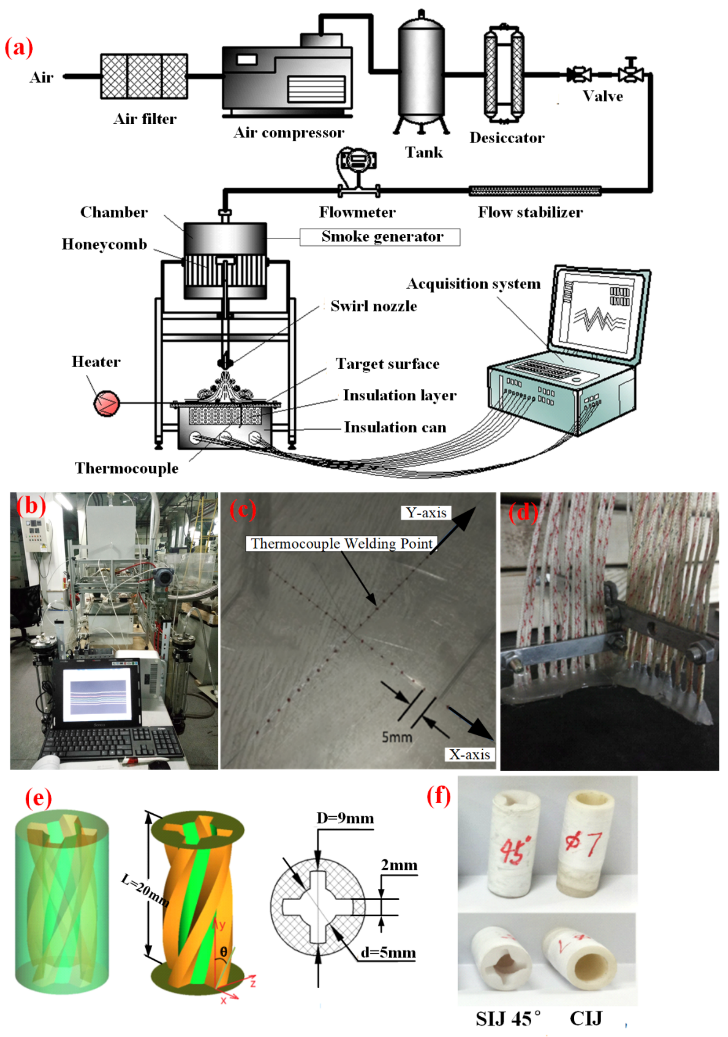
2.1. Experimental Facility

Diagrams of the experimental system are presented in Figure 1a,b, including an air filter, plenum, air compressor, thermal insulation system, drying and dehumidifying system, the heating system, and a data acquisition system.
The threaded nozzle is expected to replace the conventional smooth round nozzle in turbine blades. Conduction and convection effects generally exist in the impingement cooling configuration of turbine blades. Therefore, the impinged plate is a 320 mm × 320 mm steel plate with a thickness of 1 mm, and it is hoped that the cooling environment is similar to the outer wall of the impingement cooling method in turbine blades. In other words, the experimental data are the result of the combination of convection and heat conduction effects. Of course, the local Nu is also the combined heat transfer coefficient. It is different from the common heat transfer coefficient on the thin heated film, with only a convective effect.
A flowmeter was used to assess the air flow rate of the jet. In order to meet the experimental requirements at different Re, two glass rotameters, LZB-15 and LZB-25, were used, with corresponding measurement ranges of 0.4–4 m3/h and 2.5–25 m3/h, respectively, as shown in Figure 1b. Four pressure probes (ROSEMOUNT 3051 CD1A52A1AM5B4DF pressure transmitters) were used to measure the relative pressure at the inlet of the nozzle, with a measurement range of 0–6.22 KPa. The measuring point was arranged at the outlet of the air-collecting chamber below, that is, the inlet of the experimental nozzle, and the reference pressure was connected with the atmospheric pressure. Forty-one cross-arranged E-type thermocouples, with a measurement range of −200–900 °C, welded to the lower surface of the plate were applied to measure the plate temperature, which was held by a bracket (Figure 1c,d). The heating system comprises a short-circuit heater, which outputs high current and low voltage, with a maximum output current of 4000 A and a maximum output voltage of 10 V.
Figure 1e shows a schematic diagram of the nozzles during the experiments. Three-dimensional (3D) printing technology was used to fabricate the nozzle, with an accuracy of ±0.2 mm. A guiding tube with a height of 10 mm was added to the upper part of the nozzle in the hope that the airflow enters the nozzle in a stable state, and in actual use, the large pressure-stabilizing chamber will ensure the stability of the inlet airflow. A smooth tube with an inside diameter measuring 7 mm was also fabricated (CIJ) to analyze the effect of the threaded nozzle, as shown in Figure 1f. More information on the experimental device can be found in our previous work [34].

2.2. Data Reduction

The convective heat transfer coefficient ( h ) of the target surface is estimated as
h = q / T w T a d
The local Nu number of the target surface is evaluated by
N u = h d j / λ
The Reynolds number (Re) is given as
R e = d j ν ρ / μ
where d j is the equivalent diameter, which is the characteristic length simultaneously ( d j = 0.5 d + D ). D, d are the maximum and minimum inner diameters of the threaded nozzle, respectively, as shown as Figure 1e. T w is the average test temperature of the target, T a d is the inlet temperature of the jet, λ is the thermal conductivity of air, ν is the mean coolant velocity, ρ is the coolant density, and μ is the aerodynamic viscosity.
The equations to obtain the uncertainty of the Re and local Nu are shown as
ω N u = N u q t a r ω q t a r 2 + N u d j ω d j 2 + N u k ω k 2 + N u Δ T ω Δ T 2 1 / 2
ω R e = R e Q ω Q 2 + R e ρ ω ρ 2 + R e d j ω d j 2 + R e μ ω μ 2 1 / 2
The Re uncertainty is 2.56%, and the Nu uncertainty is 2.1% using the tolerances of the measuring instruments, as shown in Table 1.
ω R e R e = 2.56 %
ω N u N u = 2.10 %

3. Numerical Method

3.1. Model Setup

The structured grids are generated using the software ANSYA ICEM 17.0. Figure 2 shows the overall view of the mesh. O-type grids are especially used on all cylindrical parts to improve the grid quality, with a maximum mesh of no more than 0.5 mm. The spiral groove adopts a structured grid, the near-wall surface is encrypted to 0.1 mm, the grid gradient is 1.2, and the maximum grid is no more than 0.2 mm. In the jet space, the local grid applied in the near-wall regions is 0.2 mm with y+ = 30 to ensure that the first layer of the grid near the wall falls in the turbulent development zone, which is suitable for the selected turbulence model of the RNG k-ε model. The final mesh number is 2.20 million. In addition, 15 grid points in the boundary layer and standard wall functions are applied.
The total temperature at the inlet is 300 K, the turbulence intensity is 5%, and the specific mass-flow inlet in the –y-direction is defined as Re ( m = R e π d j μ / 4 , where m is the mass flow rate of the jet). The pressure outlet is defined as the atmosphere, and the target surface is defined as constant heat flux (q = 3 kW / m 2 ).
The commercial software ANSYS FLUENT 17.0 is used to solve the three-dimensional steady state Reynolds-averaged Navier–Stokes (RANS) equations, as well as the RNG   k ε turbulence model. The finite volume method is utilized to solve the equations in each control volume. A second-order format with high accuracy is applied to discretize the convective term. When all root-mean-square residuals of the mass, momentum, and energy equations are less than 10−5, the results are regarded to be sufficiently accurate.
The governing equations to solve the above three-dimensional problem are the continuity equation, momentum equation and energy equation. A detailed introduction is presented in [5].
According to our previous work [32,33], the RNG   k ε model is more suitable for simulating swirling impinging jets, and it provides better stability and higher computational efficiency. Therefore, it is applied in this work.
The RNG   k ε turbulence model is as follows [35],
t ρ k + x i ρ k u i = x j α k μ e f f k x j + G k ρ ε
t ρ ε + x i ρ ε u i = x j α ε μ e f f ε x j + C 1 ε ε k G k + C 3 ε G b C 2 ε ρ ε 2 k R ε
where α k and α ε are the inverse effective Prandtl numbers for k and ε , respectively, G k represents the generation of turbulence kinetic energy due to the mean velocity gradients, and μ e f f represents the effective viscosity coefficient.

3.2. Verification of the Numerical Method

In order to ensure the accuracy of the selected turbulence model, experimental samples in [17] are selected for verification calculation. Considering the different requirements of the turbulence model used in this paper on the near-wall grid, two types of jet impingent spatial grids with different near-wall grid nodes are prepared. One is suitable for turbulence models ( SST   k ω , k ω ) that require high near-wall encryption. The first-layer grid near the wall is encrypted to 0.001 mm, and its y+ value is guaranteed to be less than 1. The other is applicable to the turbulence model ( RNG   k ε ), which requires the first-layer grid near the wall to fall in the turbulent flow development zone. The flow near the wall is fitted by the wall function, and the first-layer grid near the wall is encrypted to 0.2 mm to ensure that it is in the turbulent flow development zone.
Figure 3a shows the calculated values of N u under different turbulence models. The distribution trend of the calculated values of the three turbulence models is basically consistent with the experimental results. In the central stagnation point region, the calculated values of the three turbulence models are relatively consistent, with a large deviation from the experimental values. It is speculated that the reason is that the air flow in the stagnation point region is slow, and the laminar flow is near the target plane. The use of the turbulence model to simulate laminar flow will inevitably lead to large prediction errors. In terms of peak point prediction, the calculated results of the RNG   k ε model are in good agreement with the experimental values, while the values of the k ω and SST   k ω models are larger than the experimental values at the two peak points, and the peak positions are migrated radially outward. The results show that the RNG   k ε model has good precision and high efficiency in the impact cooling of the rotating jet.
It is necessary to determine the appropriate grid dimension for the numerical simulation. The node numbers of the five sets of grids are 1.6 million, 1.9 million, 2.2 million, 2.5 million, and 3.5 million, respectively. Figure 3b presents the N u distribution along the x-direction at Re = 6000 and h/dj = 2. It is obvious that the grid with 2.2 million nodes is accurate enough. As a result, this grid is used in the study.
Figure 4 shows a comparison of some of the experimental data and numerical results in this work. It can be seen that the temperature of the jet impingement surface under three different working conditions (as shown in Table 2) is in good agreement with the numerical calculation results. The comparison results further indicate that the turbulence model, the gas–thermal coupling calculation method, and the corresponding mesh number used herein can accurately predict the heat transfer rate between the swirling impinging jet and the CIJ under the experimental conditions.

4. Flow Field Characteristic Analysis

4.1. Analysis of the Swirl Number

Swirl degree, also known as swirl number, is a dimensionless quantity characterizing the rotation strength of a swirling jet. Concerning the definition of the swirl number, Drake and Hubbard [36] first gave two definitions of swirl number: one is the ratio of tangential momentum flux to axial momentum flux, and the other is the tangent of the central cone angle. As in the first definition, the two momenta are not easy to be accurately measured in experiments. Most studies [37,38] adopted the second method in the analysis of the swirl number (S) and defined it as the function of the tangent value of the helix angle θ, namely
S = 2 3 1 d / D 3 1 d / D 2 tan θ
In this definition of the swirl number, the number is only related to the spiral nozzle geometric structure, ignoring the effect of the Reynolds number (Re), and this relationship follows from assumptions of plug flow axial velocity in the annular region and very thin vanes at a constant angle θ to the main direction, imparting a constant swirl velocity to the flow. When the inlet Re is changed, the strength of the vortex will also change, and the numerical simulation can obtain any velocity component in the computational domain; therefore, the first definition is used herein. According to the dimensional analysis, the following dimensionless number is used to define S [39], namely,
S = G Φ G x R
where G x and G Φ are the axial flux of the linear momentum and swirl momentum, respectively, and R is the nozzle radius. Assume that the ratio of the maximum rotational velocity and axial velocity at the nozzle is G [39], that is,
G = ω m 0 ν m 0
where ω m 0 and ν m 0 are the maximum tangential velocity and axial velocity at the nozzle, respectively. Assume that the nozzle outlet has a uniform distribution of solid rotation [39]
ω = ω m 0 r R
G ϕ = 2 π ρ 0 R r 2 u ω d r = 1 2 π ρ u m 0 ω m 0 R 3
G x = 2 π ρ 0 R r u 2 1 2 ω 2 d r = π ρ u m 0 2 R 2 1 G 2 4
By introducing Equations (12), (14) and (15) into Equation (11), S can be expressed as [39]:
S = G / 2 1 G / 2 2
The formula is applied to G 0.4 , i.e., S 0.21 . For a higher swirl number, the axial velocity distribution at the outlet deviates from the uniform distribution, and most of the fluid leaves the nozzle near the outer edge. When G > 0.4 , i.e., S > 0.21 , S can be determined by the following formula [39],
S = G / 2 1 G / 2
Figure 5 shows the S value with a 45° swirl angle of the nozzle. It shows that S is less than 0.21, and the spiral nozzle weakly rotates. To facilitate analysis under the given Re, the angle of the spiral hole with the maximum S is denoted as the transition angle S z . When the inlet Re is improved, S increases, and when Re = 7000, S z = 60 ° , Re = 4000–6000, S z = 45 ° , and S of the 45° swirl angle is shown to have a weak correlation with Re.

4.2. Analysis of Velocity Distribution of Different Sections

The jet is emitted with initial velocity υ 0 , the core potential flow produces frictions with the surrounding static fluid, and the static fluid is sucked and rolled into the jet. Due to the constant mixing with the surrounding static fluid, it is difficult for the edge part to maintain υ 0 , and the velocity gradually decreases. As the jet moves forward, the mixing with the surrounding fluid develops gradually from the edge to the center, and after a certain distance, all the sections of the jet develop into turbulence.
To verify whether the numerical simulation method adopted is effective for the conventional impingement jet, a numerical simulation was carried out on the conventional circular hole with an equivalent diameter d j   = 7 mm. The calculation results are shown in Figure 6a for when Re = 4000. The axial velocity of the cross-section obtained by the numerical calculation has the same Gaussian normal distribution as that obtained by the experiment. Additionally, the dimensionless data obtained basically fall on the same normal distribution curve, as shown in Figure 6b. These are consistent with the analytical results of Forthmann’s experiment [40], indicating that the numerical calculation method used herein can better predict the flow pattern of the conventional jet.
Figure 6c is the axial velocity distribution diagram of the sections at different positions along the x-direction of SIJ 45°. The velocity distribution of each section shows a certain similarity, with the maximum velocity on the axis line, and the farther out from the axis, the smaller the velocity is. When h > 3 d j , the axial velocity υ m at the section starts to be smaller than the velocity of core potential flow υ 0 ; that is, the initial section ends, and the swirling jet enters the fully developed section of turbulence.
Figure 6d is the dimensionless velocity distribution on different sections along the x-direction of SIJ 45°. The velocity of the section of the swirling jet is the same as that of the conventional impingement jet, and the axial velocity of the section has a certain self-similarity. The difference is that the dimensionless value of the half-width of the swirling jet velocity does not strictly fall on the same normal distribution curve but grows with the distance from the exit. When h > 4 d j , self-similarity begins to emerge, which is because the longer the distance from the outlet, the faster the tangential velocity dissipation is, and the weaker the influence on the sectional velocity is. Meanwhile, the axial velocity of the section of the swirling jet tends to be the same as that of the conventional jet.
Figure 6e,f shows the axial velocity and dimensionless distribution diagram of the sections at different positions along the x = z direction of SIJ 45°. As the jet spacing increases, smaller peaks appear in the peripheral at about x = 11   mm , which indicates that peripheral heat transfer rate increases along the x = z direction. The self-similarity of the core region of the jet in the x = 8   mm region also shows the characteristics of a weakly swirling jet in the x = z direction, which is the same as that in the x = 0 direction. At x = 8   mm , the wall escaping airflow meets the entrainment backflow, and the radial velocity of the airflow is almost zero. Then, the airflow passes over the encounter area and accelerates under the entrainment of the escaping airflow. When it accelerates to about x = 11   mm , the radial velocity decreases gradually.

4.3. Analysis of the Attenuation of Tangential Velocity

The rotating jet flows out of the nozzle at an initial velocity, and the core potential flow is drawn into the jet by friction with the stationary fluid around it. Due to the existence of tangential velocity, it will increase the mixing effect with the surrounding stationary fluid, thus increasing the spread area and mass flow rate of the cooling jet. So, the area of the heat transfer region and its heat transfer rate will increase accordingly. Figure 7 shows the attenuation curve of tangential velocity (ω) of SIJ 45°. It can be observed that the airflow rotates outside the center at the exit of the nozzle, and the tangential velocity gradually decreases with the further development of the jet. When h 4 d j , the tangential velocity almost decays to 0, and when h = 1 d j and h = 2 d j , the tangential velocity has multiple peaks.
The tangential velocity vectors at different jet distances are intercepted for further analysis, as shown in Figure 8. When h = 1 d j , the airflow ejected from the nozzle rotates and diffuses around, is sucked and coiled by the core potential flow of the central hole, flows to the central hole, and then is carried and outflows by the rotating airflow in the center, resulting in four strong vortices with the symmetrical distribution. This also explains why the tangential velocity has multiple peaks of positive and negative alternations in the x-direction of the cross-section. As the jet continues to develop, the core potential flow gradually weakens. When h 4 d j , the core of the potential flow is interrupted, and then the entrapment capacity of the central flow is further weakened. Only a small amount of the tangential airflow scattered along the center is sucked back to the center and continues to diffuse around in a weak rotational condition.
Figure 7c is the tangential velocity contour in the x = 0 section. The peak position shows an oscillating behavior, increases from h = 0 to h = 1 d j , decreases up to h = 3 d j , finally increases again between h = 3 d j and h = 4 d j , and eventually gradually goes down along the radial position.

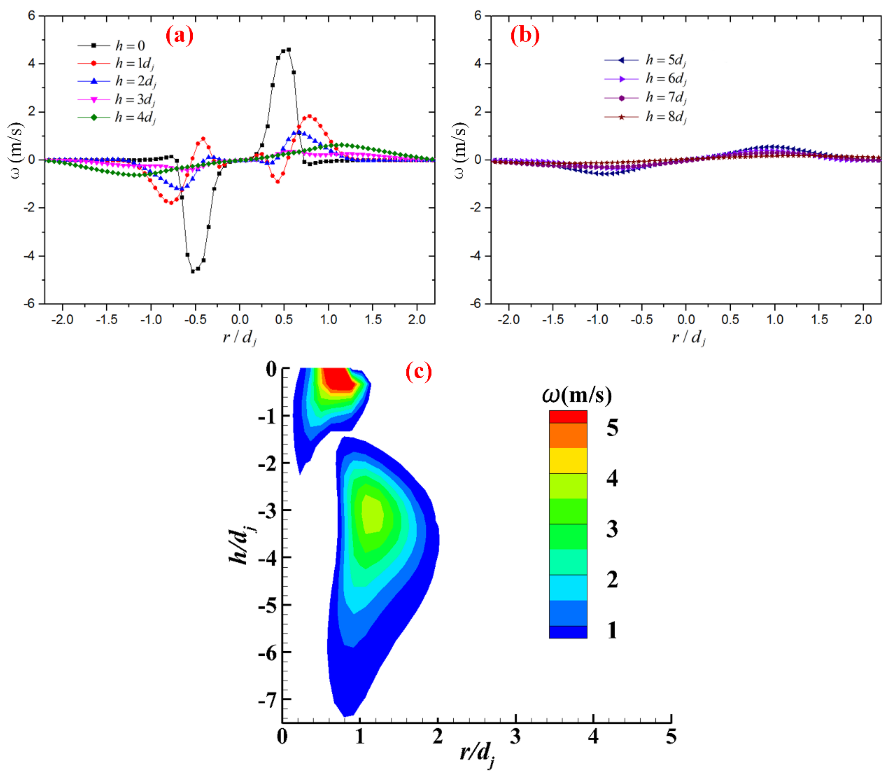
4.4. Analysis of the Vortex

To further analyze the flow characteristics of the swirling jet flow field, the “Q-Criterion” describing the vortex intensity of the flow field is introduced, and the three-dimensional Vortex Core in the flow field can be displayed by the Vortex Core Region function, which can be described as [41,42]:
Q = 0.5 ( Ω i j Ω i j Ψ i j Ψ i j )
Ω i j = 0.5 u i x j u j x i
Ψ i j = 0.5 u i x j + u j x i
where Ψ i j   and   Ω i j represent symmetric and antisymmetric components of the velocity gradient.
Figure 9 shows the three-dimensional vortex distribution of SIJ 45° and the CIJ. The intensity of the vortex in the CIJ is very low, the cool air flows gently from the nozzle to the target surface, and no large vortex flow is formed in the jet space. By contrast, the flow of SIJ 45° forms a vortex flow with very high intensity in the spiral channel, and then the flow is ejected to the target surface in the same state along the direction of the spiral channel, forming a vortex flow with high intensity in the jet space. Compared with the CIJ, the vortex flow of SIJ 45° effectively enhances the gas flow in the jet space, thus improving the heat transfer rate and heat transfer uniformity of the target surface.
For the CIJ, the ability of airflow to escape in all directions is the same, with obvious symmetry, as shown in Figure 9b. For SIJ 45°, under the action of tangential velocity airflow, the entrainment effect on the surrounding airflow is stronger so that more cold airflow acts on the target surface and the tangential airflow forms large-scale vortices in the four escape directions at the same time.

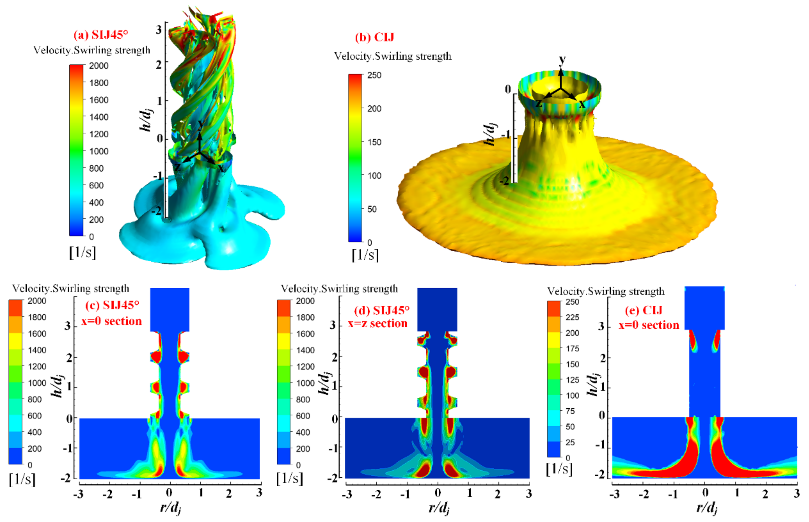
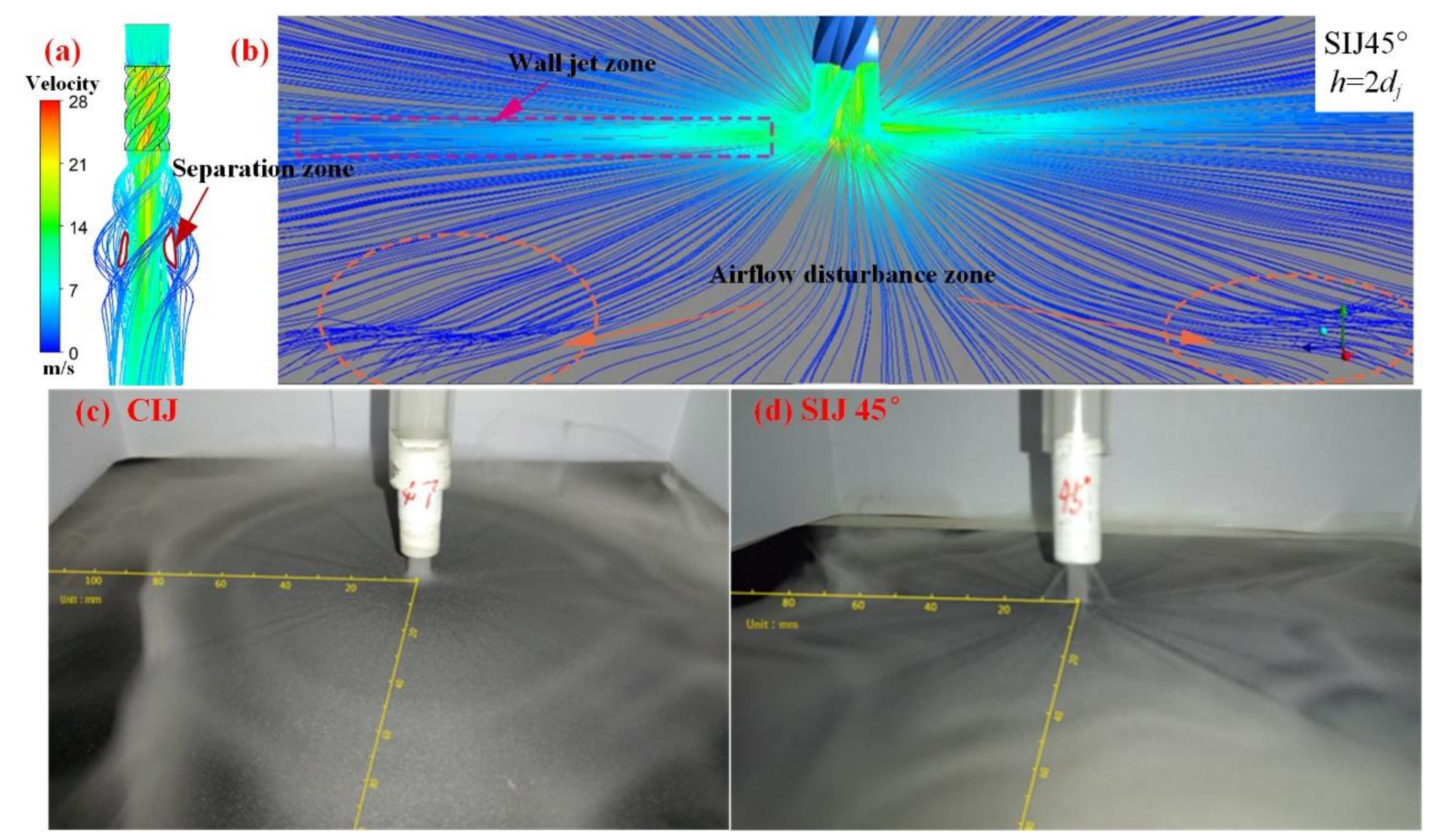
4.5. Analysis of the Flow Field Structure

Figure 10a shows the numerical simulation result of the nozzle outlet. After the airflow is ejected from the spiral nozzle, the swirling airflow is separated from the circular jet flow; that is, between the peripheral rotating jet flow and the central jet flow, a cyclone separation zone appears. However, the center hole jet does not diffuse immediately after it is ejected from the jet nozzle. Instead, a small contraction appears first and then begins to diffuse.
Figure 10b shows that after the jet is ejected, the central area of the jet maintains a relatively good near-wall jet, the airflow velocity in this area is relatively high, and the streamline maintains well. With the further development of the wall jet, the flow velocity gradually decreases, and disturbance begins to appear. Such disturbance is not uniformly distributed along the circumferential direction but is sandwiched between the strong jet area on the wall. The strong jet area on the wall is generated by the superposition of the airflow of the four spiral channels and the wall jet of the central hole after impinging on the wall.
Figure 10c,d shows the smoke flow field for the CIJ and SIJ 45° at Re = 6000 and h/dj = 2. For the CIJ, after the airflow impinges on the target surface, a uniform scattered wall jet is generated. The velocity begins to fluctuate and weaken, and there is no recirculation entrainment at r / d j = 7 . When the jet continues radially outward, the velocity is further decreased, the airflow disturbance is enhanced, and the wall jet starts to split, resulting in a strong backflow vortex at about r / d j = 12 . For SIJ 45°, the wall jet becomes even compared with the CIJ, the wall jet scatters in the “petal” type, and the backflow is further weakened in the whole jet area.
Figure 11a intercepts the streamline and velocity field of the jet space for SIJ 45° at h = 4 d j . It can be seen that after the cooling air is ejected from the nozzle, it impinges on the wall and forms a secondary jet. Some of the wall jets flow out of the jet space along the radial direction, while some of them generate entrainment backflow in the radial outward flow process, forming a strong backflow entrainment vortex. Another part of the wall jet flow also produces backflow vortices in the process of radial outward flow, but the difference is that the backflow vortices of this part are affected by the dual influence of the wall jet and tangential swirl and become spiral vortices and flow out in the radial direction. Hence, the flow field can be considered a complex flow field in which the wall jet, reflux vortex, and spiral vortex co-exist and interact with each other.
The velocity vector at h = 1 d j is shown in Figure 11b. As can be seen, the airflow does not form a backflow vortex in four “escape” channel directions, and the temperature gradient in this direction is relatively gentle. On the contrary, between the two “escape” channels, the wall jet flow forms a strong backflow vortex at the position of about r = 6 d j , so the jet flow near the wall decreases outward from the separation boundary position of the vortex. The ambient airflow outside is sucked up by the negative pressure generated by the central high-speed jet, forming a backflow vortex. The flow separation occurs, the cooling effect becomes worse, and a large temperature gradient forms. Therefore, the swirling jet can strengthen the cooling of the target surface along the direction of airflow escape.

4.6. Flow Model for Swirling Impinging Jets

The flow is ejected from the inner circular tube and four spiral channels, forming a jet flow field together. The inner circular tube produces vertical impingement flow similar to the CIJ, which is mainly to cool the central area. Four spiral channels produce four rotating jet flows, which rotate and diffuse around and draw into the stationary fluid around by the friction. Due to the emergence of the swirling flow, the cooling effect of the peripheral area is greatly expanded, and the tangential velocity further takes away more heat and improves the heat transfer consistency. It can be concluded that the radial spread of the swirling flow leads to more entertainment of the surrounding air than the CIJ. A schematic map for swirling impinging jets can be seen in Figure 12.

5. Heat Transfer Characteristics of the Jets from the Threaded Nozzles

5.1. Comparison of Heat Transfer and Flow Characteristics of SIJ 45° and CIJ

In order to estimate the heat transfer performance and compare SIJ 45° and the CIJ at R e = 12,000 and h / d j = 2 , the square zone of x / d j 7 and y / d j 7 is selected. Figure 13a,b presents the local temperature contours. In general, the temperature distribution of SIJ 45° is smaller than the temperature distribution of the CIJ. Figure 13c,d presents the local Nu contours. It can be found that Nu is relatively high, along with the “escape” channel directions, which is because the swirling airflow ejected from the spiral nozzle enhances the heat transfer. By comparison, the CIJ has the same heat transfer effect in all directions. Figure 13e,f presents the turbulent kinetic energy (k) contours. The turbulent kinetic energy (k) is apparently larger in SIJ 45° than in the CIJ, especially near the nozzles. The distribution trend of the turbulent kinetic energy (k) is the same as that of Nu.
Figure 13g,h shows the streamlines and velocity contours of the x = 0 section for SIJ 45° and the CIJ. After passing through the nozzles, the airflow has a high speed, but due to the friction role of the surrounding stagnation flows, the jet in the core region decays rapidly. After impinging on the target surface, the air diffuses to both circumferential sides and forms obvious vortices in the jet space. Compared with the CIJ, the center velocity of SIJ 45° is higher, which is due to the increase in the flow resistance of the spiral grooves, and more air flows out from the center through-hole, resulting in the increase in the velocity in the central region of the nozzles. At the same time, the swirling effect of the tangential airflow at the exit of the spiral groove leads to two “fin-like” flow vortex areas in the region of the free shear boundary layer. Along the flow direction of the jets, the “fin-like” area quickly decays and disappears.

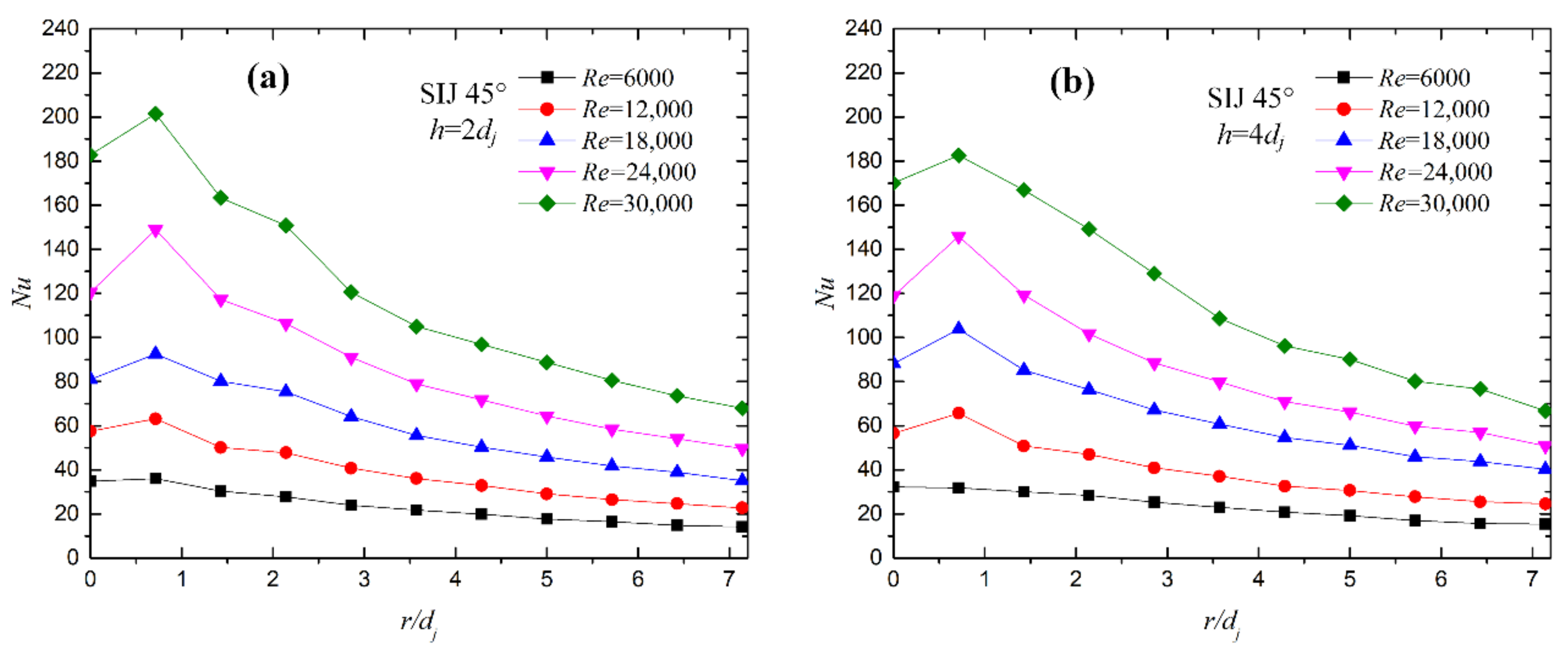
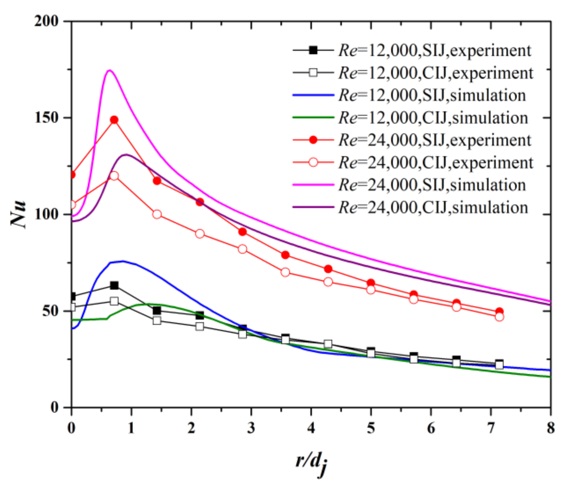
5.2. Effect of Re on Heat Transfer Characteristics

Figure 14a,b gives the variation of the local Nu of the target surface along the radial direction for SIJ 45° at h / d j = 2 , 4 and R e = 6000 30,000 . The local Nu increases as the Re increases. The maximum Nu does not appear at the center point but at the periphery of the center point about r / d j = 0.7 , and the peak value increases as Re increases. When Re is small, the swirling flow developed by the spiral grooves helps to enhance the heat transfer around the stagnation point of the target surface. It is speculated that the reason may be that the airflow ejected by the spiral grooves superimposes with the wall jet of the central hole, which intensifies the heat transfer. Additionally, Nu increases as Re increases, which is the same as the CIJ. However, from the point of view of the increased rate, the number of Re is greater than that of Nu.

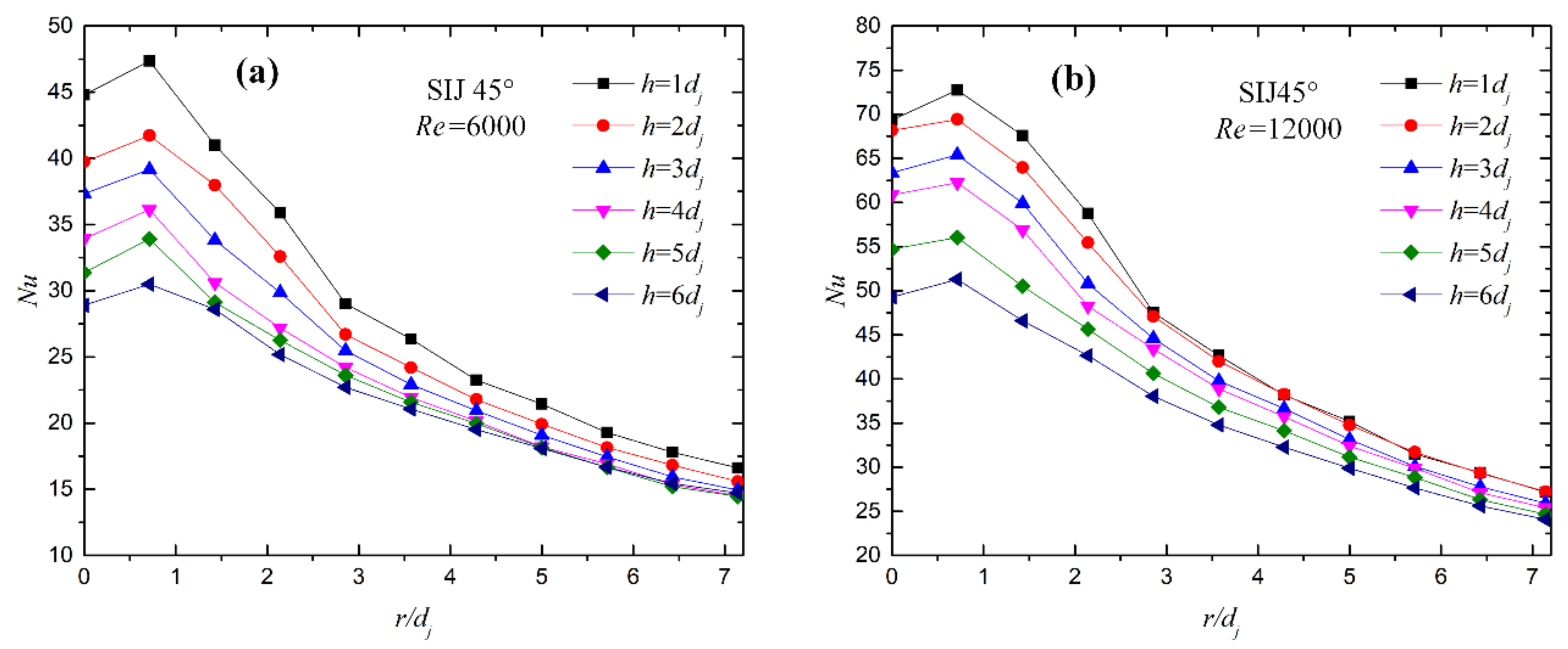
5.3. Effect of Jet Spacing on Heat Transfer Characteristics

Figure 15a,b gives the variation of the local Nu with h / d j = 1 8 at Re = 6000 and 12,000. It can be seen that the experimental results under the two Re conditions show that the overall heat transfer rate of the target surface decreases with the increase in jet spacing. When Re = 6000, Nu has a peak value at about r / d j = 0.7 . When Re = 12,000, the peak value of Nu is weakened. As the h / d j decreases, the maximum peripheral Nu gradually weakens. When the jet spacing is small and Re is low, the distribution characteristics of Nu are similar to that of the CIJ and tend to be a “bell-shaped” distribution.

5.4. Comparison of Pressure Loss Coefficient

The non-dimensional pressure loss coefficient (K) is defined as
K = Δ p / 0.5 ρ V ¯ 2
where Δ p is the pressure drop between the inlet and the outlet (there are four differential pressure gages to measure the pressure in the chamber, and the difference value between it and the atmospheric pressure is the Δp), ρ is the density of air corresponding to supply pressure, and V   ¯ is the average velocity at the exit of the nozzle.
The pressure loss coefficient (K) for SIJ 45° and the CIJ at R e = 6000 30,000 is shown in Figure 16. It is observed that the pressure loss coefficients for SIJ 45° are higher than those for the CIJ, 159.17% on average. In addition, SIJ 45° has the least chamber pressure of the thread nozzle, lower than the other three kinds (insert, built-in torsion, and guide vane) [43]; that is, for the thread nozzle, the airflow resistance is relatively small, and the air source chamber does not need to bear too much pressure. This is because the thread nozzle is set in the periphery of the center hole, which reduces the airflow friction. In addition, the high operating pressure has an impact on the structural strength and safety of the equipment in practical applications and brings about a large loss of pump power. Under two different nozzles, as Re increases, the pressure loss coefficient gradually weakens, which shows that the nozzle has a relatively good flow capacity under high Re.

5.5. Globally Averaged N u

The N u correlation of the SIJ is meaningful to devise a new nozzle structure. The N u ¯ is a function of Re and h / d j as analyzed earlier. An empirical correlation of N u ¯ is assumed as
N u ¯ = a R e b h / d j c
The multiple linear regression method is applied to fit Correlation (22), and we obtained
N u ¯ = 0.02497 R e 0.815 h / d j 0.131
The fitting accuracy (R2) of Correlation (23) is 0.974, and it is applicative within the range of 6000 R e 30,000 , and 1 h / d j 8 in the target region of r / d j 7 for SIJ 45 ° (within a circular area with a radius of 50 mm, approximately 7854 mm2). Figure 17 compares the calculated values of Equation (23) and the experimental values. The average error between the correlation and experimental values is 6.57%, and most points are within ± 10%, which are calculated according to N u m o d e l N u e x p e r i m e n t a l / N u e x p e r i m e n t a l . Hence, the correlation can precisely predict the N u ¯ of SIJ 45 ° .
To compare the heat transfer characteristics of SIJ 45° and the CIJ, the correlation formula herein is compared with that in [44]. Figure 18 shows the comparison of average N u in the target region of r / d j   7 for SIJ 45 ° and the CIJ within the range of h / d j = 3 6 and R e = 10,000 30,000 . It can be seen that Nu increases by 69.18% on average under 20 different working conditions, which is attributed to the fact that the heat transfer rate is obviously enhanced by the effect of superimposed airflow.
Figure 19 gives a comparison of Nu values between SIJ 45° and the CIJ with experimental and numerical methods. It can be seen that Nu values of SIJ 45° are higher than those of the CIJ, which coincides with the Nu contours in Figure 11. In addition, the experimental results are in good agreement with the numerical results.

6. Conclusions

In this work, an experimental system is established to study the flow field and heat transfer characteristics of SIJ 45°, and a nozzle is fabricated. The numerical results agree well with the experimental results, which demonstrate the numerical calculation method. The smoke flow field is studied, and the effects of Re and h/dj on the Nu of SIJ 45° are investigated experimentally. The following conclusions can be drawn from this study.
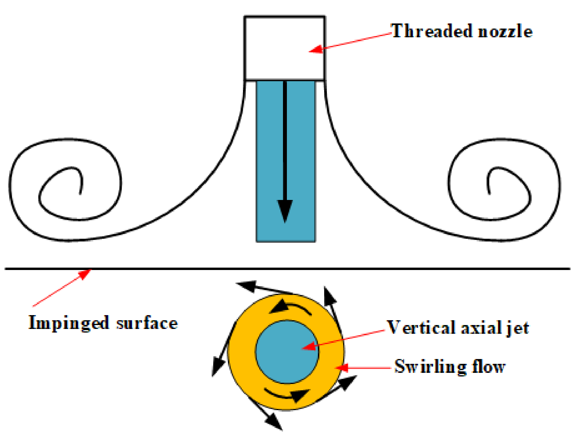
  • SIJ 45° generates swirling flow and a central vertical jet. Due to the tangential velocity, flow diffusivity is enhanced compared with that of the CIJ, which takes away more heat.
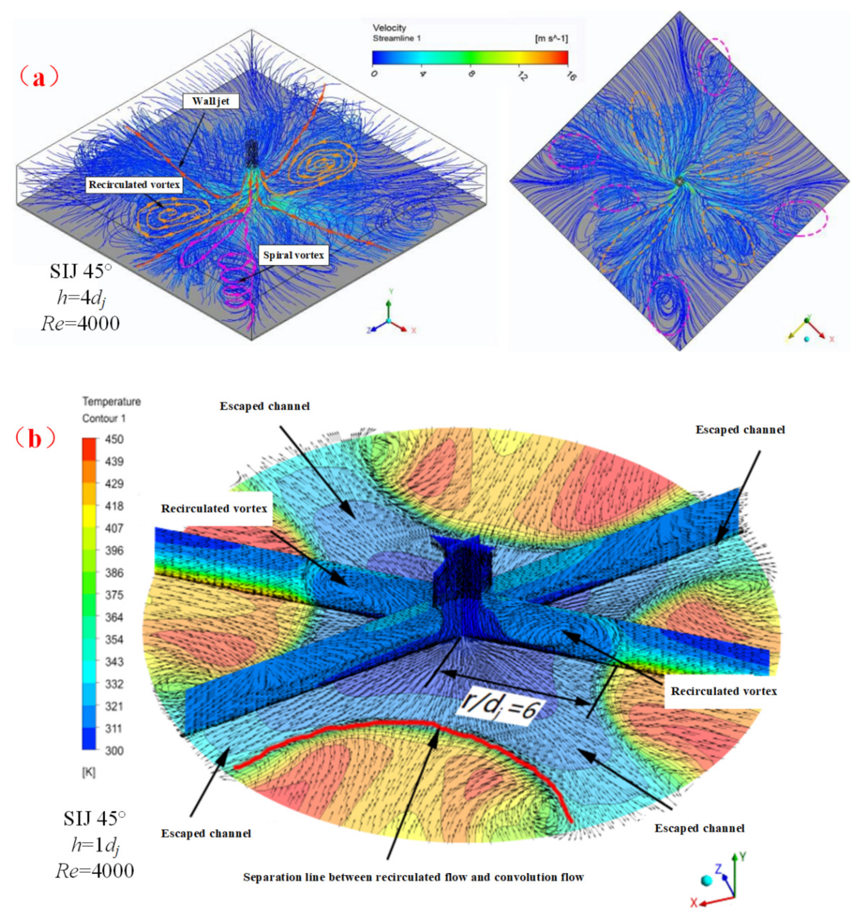
  • The airflow ejected from SIJ 45° rotates and diffuses around and forms four strong vortices with a symmetrical distribution, which explains why the tangential velocity appears with multiple peaks of positive and negative alternations.
  • The flow field ejected from SIJ 45° can be considered a complex flow field, in which the vertical impingement flow and the swirling flow interact with each other.
  • As the h / d j increases, the Nu for SIJ 45 ° gradually decreases, and the maximum Nu transfers to the peripheral area, which enhances the heat transfer uniformity.
  • An empirical correlation of N u ¯ is built within the range of 6000 R e 30,000 , 1 ≤ h/dj ≤ 8 for SIJ 45 ° , which agrees well with the experimental results.

Author Contributions

Conceptualization, L.X. (Liang Xu) and T.Y.; methodology, L.X. (Liang Xu); software, T.Y.; validation, Y.S. and L.X. (Lei Xi); formal analysis, L.X. (Lei Xi); investigation, J.G.; resources, Y.L.; data curation, L.X. (Lei Xi); writing—original draft preparation, T.Y.; writing—review and editing, L.X. (Liang Xu); visualization, L.X. (Lei Xi); supervision, Y.S.; project administration, J.G.; funding acquisition, L.X. (Liang Xu). All authors have read and agreed to the published version of the manuscript.

Funding

This research was funded by the National Key R&D Program of China (2018YFB1106400), the National Natural Science Foundation of China (Grant No.51876157), and the Natural Science Foundation of Shanxi Province in China (2019JM-096).

Conflicts of Interest

The authors declare no conflict of interest.

Nomenclature

CIJConventional impinging jet
djEquivalent diameter (mm)
GRatio of the maximum rotational velocity and axial velocity
G x Axial flux of linear momentum
hJet spacing (distance from nozzle to impingement surface) (mm)
KPressure loss coefficient
NuNusselt number
R2Fitting accuracy
rRadial distance from the stagnation point (mm)
SIJ45°Swirling jet with a swirling angle of 45°
T w Average test temperature of the target (K)
ΩijAntisymmetric part of the velocity gradient tensor (s-1)
ω m 0 Maximum tangential velocity (m/s)
θSwirl angle (°)
ν Mean coolant velocity (m/s)
μ Aerodynamic viscosity (Pa s)
α ε Inverse effective Prandtl numbers for ε
dMinimum inner diameter of the threaded nozzle (mm)
DMaximum inner diameter of the threaded nozzle (mm)
G k Turbulence kinetic energy due to the mean velocity gradients
G Φ axial flux of swirl momentum
h Heat transfer coefficient (W/m2 K)
kTurbulent kinetic energy
RNozzle radius (mm)
ReReynolds number
SSwirl number
T a d Inlet temperature of the jet (K)
V   ¯ Average velocity (m/s)
ΨijPositive symmetric part of the velocity gradient tensor.
ν m 0 Maximum axial velocity (m/s)
λThermal conductivity of air (W/m K)
ρ Coolant density (kg/m3)
α k Inverse effective Prandtl numbers for k
μ e f f Effective viscosity coefficient.

References

  1. Alenezi, A.; Almutairi, A.; Alhajeri, H.; Addali, A.; Gamil, A. Flow Structure and Heat Transfer of Jet Impingement on a Rib-Roughened Flat Plate. Energies 2018, 11, 1550. [Google Scholar] [CrossRef] [Green Version]
  2. Kareem, Z.S.; Balla, H.H.; AbdulWahid, A.F. Heat transfer enhancement in single circular impingement jet by CuO-water nanofluid. Case Stud. Therm. Eng. 2019, 15, 100508. [Google Scholar] [CrossRef]
  3. Kura, T.; Wajs, J.; Fornalik-Wajs, E.; Kenjeres, S.; Gurgul, S. Thermal and Hydrodynamic Phenomena in the Stagnation Zone—Impact of the Inlet Turbulence Characteristics on the Numerical Analyses. Energies 2020, 14, 105. [Google Scholar] [CrossRef]
  4. Martínez-Filgueira, P.; Zulueta, E.; Sánchez-Chica, A.; Fernández-Gámiz, U.; Soriano, J. Multi-Objective Particle Swarm Based Optimization of an Air Jet Impingement System. Energies 2019, 12, 1627. [Google Scholar] [CrossRef] [Green Version]
  5. Yang, Y.; Liu, H.; Mao, W.; Song, Z.; Wang, H. Study on the Impact Pressure of Swirling-Round Supercritical CO2 Jet Flow and Its Influencing Factors. Energies 2020, 14, 106. [Google Scholar] [CrossRef]
  6. Mohamed Illyas, S.; Ramesh Bapu, B.R.; Venkata Subba Rao, V. Experimental Analysis of Heat Transfer and Multi Objective Optimization of Swirling Jet Impingement on a Flat Surface. J. Appl. Fluid Mech. 2019, 12, 803–817. [Google Scholar] [CrossRef]
  7. Singh, P.; Chander, S. Study of flow field and heat transfer characteristics for an interacting pair of counter-rotating dual-swirling impinging flames. Int. J. Therm. Sci. 2019, 144, 191–211. [Google Scholar] [CrossRef]
  8. Fénot, M.; Dorignac, E.; Lalizel, G. Heat transfer and flow structure of a multichannel impinging jet. Int. J. Therm. Sci. 2015, 90, 323–338. [Google Scholar] [CrossRef]
  9. Ahmed, Z.U.; Al-Abdeli, Y.M.; Guzzomi, F.G. Flow field and thermal behaviour in swirling and non-swirling turbulent impinging jets. Int. J. Therm. Sci. 2017, 114, 241–256. [Google Scholar] [CrossRef]
  10. Ahmed, Z.U.; Al-Abdeli, Y.M.; Matthews, M.T. The effect of inflow conditions on the development of non-swirling versus swirling impinging turbulent jets. Comput. Fluids 2015, 118, 255–273. [Google Scholar] [CrossRef]
  11. Wu, F.; Li, L.; Wang, J.; Fan, X.; Du, C. Numerical investigations on flow and heat transfer of swirl and impingement composite cooling structures of turbine blade leading edge. Int. J. Heat Mass Transf. 2019, 144, 118625. [Google Scholar] [CrossRef]
  12. Debnath, S.; Khan, M.H.U.; Ahmed, Z.U. Turbulent swirling impinging jet arrays: A numerical study on fluid flow and heat transfer. Therm. Sci. Eng. Prog. 2020, 19, 100580. [Google Scholar] [CrossRef]
  13. Chouaieb, S.; Kriaa, W.; Mhiri, H.; Bournot, P. Swirl generator effect on a confined coaxial jet characteristics. Int. J. Hydrogen Energy 2017, 42, 29014–29025. [Google Scholar] [CrossRef]
  14. Liu, L.; Zhang, J.; Liu, S.; Wang, K.; Gu, H. Decay law and swirl length of swirling gas-liquid flow in a vertical pipe. Int. J. Multiph. Flow 2021, 137, 103570. [Google Scholar] [CrossRef]
  15. Yan, J.; Gui, N.; Xie, G.; Gao, J. Direct Numerical Simulation and Visualization of Biswirling Jets. Adv. Mech. Eng. 2015, 6, 193731. [Google Scholar] [CrossRef]
  16. Wannassi, M.; Monnoyer, F. Fluid flow and convective heat transfer of combined swirling and straight impinging jet arrays. Appl. Therm. Eng. 2015, 78, 62–73. [Google Scholar] [CrossRef]
  17. Huang, L.; El-Genk, M.S. Heat transfer and flow visualization experiments of swirling, multi-channel, and conventional impinging jets.pdf. Int. J. Heat Mass Transf. 1998, 41, 583–600. [Google Scholar] [CrossRef]
  18. Markal, B. The effect of Total flowrate on the cooling performance of swirling coaxial impinging jets. Heat Mass Transf. 2019, 55, 3275–3288. [Google Scholar] [CrossRef]
  19. Hindasageri, V.; Vedula, R.P.; Prabhu, S.V. Heat transfer distribution of swirling flame jet impinging on a flat plate using twisted tapes. Int. J. Heat Mass Transf. 2015, 91, 1128–1139. [Google Scholar] [CrossRef]
  20. Duangthongsuk, W.; Wongwises, S. An experimental investigation of the heat transfer and pressure drop characteristics of a circular tube fitted with rotating turbine-type swirl generators. Exp. Therm. Fluid Sci. 2013, 45, 8–15. [Google Scholar] [CrossRef]
  21. Kumar, S.S.; Hindasageri, V.; Prabhu, S.V. Local heat transfer distribution on a flat plate impinged by a swirling jet generated by a twisted tape. Int. J. Therm. Sci. 2017, 111, 351–368. [Google Scholar] [CrossRef]
  22. Wongcharee, K.; Chuwattanakul, V.; Eiamsaard, S. Influence of CuO/water nanofluid concentration and swirling flow on jet impingement cooling. Int. Commun. Heat Mass Transf. 2017, 88, 277–283. [Google Scholar] [CrossRef]
  23. Wongcharee, K.; Chuwattanakul, V.; Eiamsaard, S. Heat transfer of swirling impinging jets with TiO2-water nanofluids. Chem. Eng. Process. Process. Intensif. 2017, 114, 16–23. [Google Scholar] [CrossRef]
  24. Chang, S.W.; Shen, H.-D. Heat transfer characteristics of swirling impinging jet-arrays issued from nozzle plates with and without webbed grooves. Int. J. Therm. Sci. 2020, 148, 106155. [Google Scholar] [CrossRef]
  25. Ortega-Casanova, J. CFD and correlations of the heat transfer from a wall at constant temperature to an impinging swirling jet. Int. J. Heat Mass Transf. 2012, 55, 5836–5845. [Google Scholar] [CrossRef]
  26. Ortega-Casanova, J.; Granados-Ortiz, F.J. Numerical simulation of the heat transfer from a heated plate with surface variations to an impinging jet. Int. J. Heat Mass Transf. 2014, 76, 128–143. [Google Scholar] [CrossRef]
  27. Amini, Y.; Mokhtari, M.; Haghshenasfard, M.; Barzegar Gerdroodbary, M. Heat transfer of swirling impinging jets ejected from Nozzles with twisted tapes utilizing CFD technique. Case Stud. Therm. Eng. 2015, 6, 104–115. [Google Scholar] [CrossRef] [Green Version]
  28. Chattopadhyay, H. Numerical investigations of heat transfer from impinging annular jet. Int. J. Heat Mass Transf. 2004, 47, 3197–3201. [Google Scholar] [CrossRef]
  29. Salman, S.D.; Kadhum, A.A.H.; Takriff, M.S.; Mohamad, A.B. Experimental and Numerical Investigations of Heat Transfer Characteristics for Impinging Swirl Flow. Adv. Mech. Eng. 2015, 6, 631081. [Google Scholar] [CrossRef]
  30. Hayat, M.Z.; Nandan, G.; Tiwari, A.K.; Sharma, S.K.; Shrivastava, R.; Singh, A.K. Numerical study on heat transfer enhancement using twisted tape with trapezoidal ribs in an internal flow. Mater. Today Proc. 2020, 46, 5412–5419. [Google Scholar] [CrossRef]
  31. Nozaki, A.; Igarashi, Y.; Hishida, K. Heat transfer mechanism of a swirling impinging jet in a stagnation region. Heat Transf. Asian Res. 2003, 32, 663–673. [Google Scholar] [CrossRef]
  32. Xu, L.; Lan, J.; Ma, Y.; Gao, J.; Li, Y. Numerical study on heat transfer by swirling impinging jets issuing from a screw-thread nozzle. Int. J. Heat Mass Transf. 2017, 115, 232–237. [Google Scholar] [CrossRef]
  33. Xu, L.; Xiong, Y.; Xi, L.; Gao, J.; Li, Y.; Zhao, Z. Numerical Simulation of Swirling Impinging Jet Issuing from a Threaded Hole under Inclined Condition. Entropy 2019, 22, 15. [Google Scholar] [CrossRef] [Green Version]
  34. Xu, L.; Yang, T.; Sun, Y.; Xi, L.; Gao, J.; Li, Y.; Li, J. Flow and heat transfer characteristics of a swirling impinging jet issuing from a threaded nozzle. Case Stud. Therm. Eng. 2021, 25, 100970. [Google Scholar] [CrossRef]
  35. Orzag, S.A.; Yakhot, V. Renormalization-Group Analysis of Turbulence. Phys. Rev. Lett. 1986, 57, 1722–1724. [Google Scholar]
  36. Drake, P.F.; Hubard, E.H. Effect of air swirl on the completeness of combustion. J. Inst. Fuel 1963, 36, 389. [Google Scholar]
  37. Bakirci, K.; Bilen, K. Visualization of heat transfer for impinging swirl flow. Exp. Therm. Fluid Sci. 2007, 32, 182–191. [Google Scholar] [CrossRef]
  38. Yang, H.Q.; Kim, T.; Lu, T.J.; Ichimiya, K. Flow structure, wall pressure and heat transfer characteristics of impinging annular jet with/without steady swirling. Int. J. Heat Mass Transf. 2010, 53, 4092–4100. [Google Scholar] [CrossRef]
  39. Gupta, A.K. Swirl Flows; Tunbridge Wells Kent England Abacus Press: Kent, UK, 1984. [Google Scholar]
  40. Forthmann, E. Uber turbulence strahlausbreitung. Diss. Gott. 1934, 319, 36–38. [Google Scholar]
  41. Kolář, V. Vortex identification: New requirements and limitations. Int. J. Heat Fluid Flow 2007, 28, 638–652. [Google Scholar] [CrossRef]
  42. Jeong, J.; Hussain, F. On the identification of a vortex. J. Fluid Mech. 1995, 285, 69–94. [Google Scholar] [CrossRef]
  43. Xu, L.; Ren, D.; Ma, Y.; Lan, J.; Gao, J. Pressure loss and heat transfer characteristics experiment of swirling impinging jet with different shape nozzles. J. Aerosp. Power 2018, 33, 2678–2686. [Google Scholar]
  44. Goldstein, R.J.; Seol, W.S. Heat transfer to a row of impinging circular air jets including the effect of entrainment. Int. J. Heat Mass Transf. 1991, 34, 2133–2147. [Google Scholar] [CrossRef]
Figure 1. (a) Scheme of the experimental device, (b) picture of the experimental device, (c) points of thermocouples, (d) fixation of thermocouples, (e) schematic diagram of nozzle, and (f) real picture of nozzles.
Energies 14 08412 g001
Figure 2. Mesh for numerical calculation.
Energies 14 08412 g002
Figure 3. Verification of the numerical method: (a) turbulence model and (b) grid independence.
Energies 14 08412 g003
Figure 4. Comparison of calculated values of target surface temperature with experimental results.
Energies 14 08412 g004
Figure 5. S of 45° swirl angle with different Re.
Energies 14 08412 g005
Figure 6. Velocity distribution of different sections: (a) CIJ, (b) dimensionless data of CIJ, (c) SIJ 45°, (d) dimensionless data of SIJ 45° along the x-direction, (e) SIJ 45°, and (f) dimensionless data of SIJ 45° along the x = z direction.
Energies 14 08412 g006
Figure 7. Attenuation curve of tangential velocity: (a,b) tangential velocity; (c) tangential velocity contour (Re = 4000, SIJ 45°).
Energies 14 08412 g007
Figure 8. Tangential velocity vector at the outlet of the nozzle (Re = 4000, SIJ 45°) for (a) h = d j , and (b) h = 2 d j .
Energies 14 08412 g008
Figure 9. Vortex contour (Re = 4000, h/dj = 2): (a) SIJ 45°, (b) CIJ, (c)in the x = 0 section for SIJ 45°, (d) in the x = z section for SIJ 45°, and (e) in the x = 0 section for CIJ.
Energies 14 08412 g009
Figure 10. Three-dimensional (3D) streamlines of SIJ 45° in (a) nozzle outlet and (b) target surface. Smoke flow field with (c) CIJ and (d) SIJ 45° (Re = 6000, h/dj = 2).
Energies 14 08412 g010
Figure 11. (a) Three-dimensional (3D) streamlines of jet space and (b) velocity field of jet space.
Energies 14 08412 g011
Figure 12. Schematic map for swirling impinging jets.
Energies 14 08412 g012
Figure 13. Comparison of SIJ 45° and CIJ: (a,b) temperature distribution, (c,d) Nu distribution, (e,f) turbulent kinetic energy (k) distribution, and (g,h) streamlines and velocity contours in x = 0 section (Re = 12,000 and h/dj = 2).
Energies 14 08412 g013
Figure 14. Experimental values of Nu distribution with different Re: (a) h = 2dj and (b) h = 4dj.
Energies 14 08412 g014
Figure 15. Experimental results of Nu with different jet spacings: (a) Re = 6000 and (b) Re = 12,000.
Energies 14 08412 g015
Figure 16. Variation of pressure loss coefficient (K) of SIJ 45° and CIJ at various Re.
Energies 14 08412 g016
Figure 17. Comparison of experimental and predicted Nu values.
Energies 14 08412 g017
Figure 18. Comparison of average Nu values of SIJ 45° and that of CIJ in [44].
Energies 14 08412 g018
Figure 19. Comparison of Nu values between CIJ and SIJ (h = 2dj).
Energies 14 08412 g019
Table 1. Measuring instruments and the uncertainty.
Measurement ParametersSymbolsMeasuring InstrumentsUncertainty
TemperatureTE-Type thermocouple1%
flow rateQFlowmeter2.5%
PressurePdifferential pressure gauge0.05%
Geometric parametersLDigital caliper0.01 mm
VoltageUVoltmeter0.2%
CurrentIAmmeter0.2%
Table 2. Experimental conditions and partial data measurement values.
ConditionSwirl Angle
(°)
Inlet   Temperature   ( K ) Outlet   Temperature   ( K ) Environment   Temperature   ( K ) Chamber Pressure
(Pa)
Flow Rate
( m 3 h )
Jet Spacing
( h / d j )
Heat Flux
( W m 2 )
Case 145296.27310.10298.451661.8332625
Case 245294.71301.22296.125902.6532746
Case 3 Φ 7 (CIJ)297.55306.23295.421081.5241035
Publisher’s Note: MDPI stays neutral with regard to jurisdictional claims in published maps and institutional affiliations.

