1. Introduction
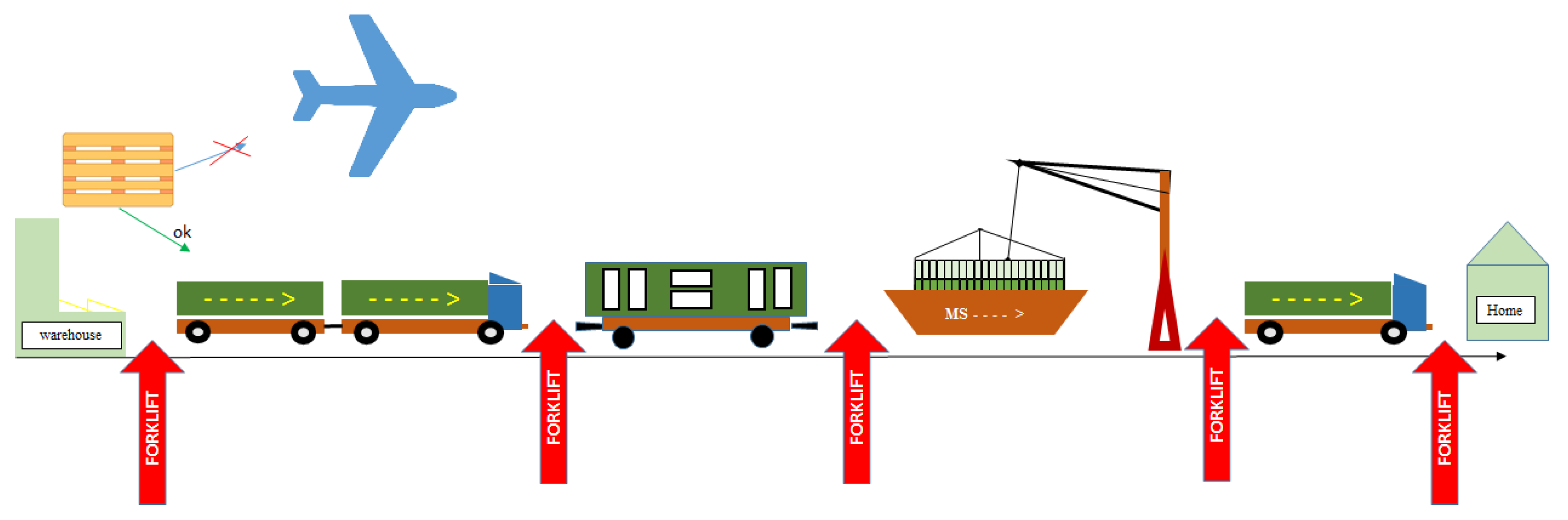
When transporting loads with a forklift, the following may occur: slipping of the load, overturning, falling from the forks, emission of harmful noise to the environment. This causes load damage [
1] such as micro dents and dings, surface scratches, coating chipping, damage to the surrounding infrastructure in case of load sliding.
The reader of the paper will learn how to limit mechanical damage to the load on a forklift truck by using additional forklift equipment. The application of this solution can reduce not only damage, but also the energy consumption of transport processes in logistics centers.
In
Figure 1, potential damage areas are marked with a red arrow to give the reader an idea of the scale of these (based on author’s own experience and [
2,
3,
4,
5,
6]). In the operation of a forklift truck, the following operating states can be distinguished: transport (P1) and handling in the vertical (P2) and horizontal (P3) planes. It is in the article that he is responsible for the energy consumption of the forklift. In the operation of a forklift truck, a solution is sought for which the energy consumption and the number of damage to the pallets will be minimal [
7].
This damage to a load that is on the forks of a forklift during P1. Insurance companies and the logistics industry are trying to formally describe, characterize, and compile lists of damages as they are needed in situations where business partners seek damages in court. Load damage, based on practical experience, is usually classified into: physical and chemical, climatic, chemical, biological, and others such as sprinkling with sand, dust, or fire.
Load damage occurs as a result of (a set of certain) several factors occurring at the same time which result in uncontrolled relocation of the load on the truck’s forks. In many cases, the cause of said relocation is the action of inertial force: on a straight section due to acceleration (positive/negative), and on a curved path due to centrifugal force.
Physical phenomena such as pressure, bending, kinking, falling, tilting, tipping, bumping, squeezing, crushing (periodic and stochastic vibrations, noise)—in companies this is called load damage due to: pulling, tipping, shifting—of the load.
The volume of load damage is on the rise as work efficiency, including forklift operations, increases and is of significant importance for the quality of the processes carried out [
8,
9]. Companies are pursuing the idea of increasing the number of forklift transport cycles in a reference time within a specific logistics system. This effect is achieved by increasing the forklift speed to its extreme values. Referring to this situation, forklift operators use to say: “the wheel of the forklift never stops, it just changes direction.” The increase in efficiency, considered a success, soon reciprocates to those in charge of quality [
10,
11] in the company in the form of customer complaints about inadequate quality levels and lack of reliability in securing load [
12].
The rest of the paper discusses the load damage syndrome, pallet damage test results, the concept of the patented invention, the application of which may reduce load damage. The paper concludes by verifying the prototype under real-world conditions and seeks answers to the question of whether this innovation promotes damage reduction.
2. Mechanism of Load Damage Occurrence
Load damage occurs due to the interaction between the load—load pallet (P)—and forks of the forklift (F) [
13]. Individual components of this system may become damaged. The interaction between (P)–(F) is illustrated in subsequent drawings (items A and C). Forklift transport of the load is possible if and only if the load is on a pallet (integrated with the pallet). Transport pallets are made of various materials from pine wood, plastics, PUR foam, cardboard (multilayer cardboard). To rule out the impact of the pallet on the amount of damage to the load in the transport process, it is only allowed to use pallets with the parameters specified by the standard [
14]. The task of assessing the condition of a pallet is usually performed in-house or outsourced to a pallet pool [
15]. The damage types in question are illustrated in
Figure 2: A–F—black color, visible traces of mould, paints, oils etc.; B—board is cracked—edges come apart—both in top and bottom boards; C—boards are so splintered that 2 (two) nails are visible; D—splinters on the lower and upper (outermost) boards with a depth of up to 1 cm along the entire length; E—board is cracked—edges come apart—both in top and bottom boards; G—splinted longitudinal members along their entire length with a depth of splintering up to 1 cm; H—fine chipping on support—marking still visible; J—typical EURO pallet; K—staple (quality control clamp of new pallet and pallet repair authenticity nail.
These are select, popular damage types [
16]. Repairs to damaged pallets can only be legally made by qualified companies that have a UIRR certificate and that register and confirm the repair with a service nail—see
Figure 2K.
Thus, the pallet material is one of the elements of the (P)–(F) friction pair. In order to easily and unambiguously determine the materials forming the friction pair, the authors recommend using: the packaging code and the knowledge that the forks of the truck (F),
Figure 3, are obligatorily made of a steel forging. For example, a package labelled: UN/1A1/Y1.4/150/06/PL/COBRO/nnn—complies with UN requirements; drum-shaped container with a detachable lid, made of steel, class Y, for substances of II and III group; gross weight 150 kg, produced in 2006 in Poland, certified by COBRO. It suffices to remember that material (P) stands for materials of groups: A, … P from the work [
17,
18].
Logistics centers (warehouses) often postpone the replacement of damaged pallets. They strive to bring it to a state of complete wear before decommissioning to maximise economic return [
19]. Some laboratories have performed independent studies of damage and durability of pallets operated in supply chains, e.g., The results of the studies [
20] permit a claim that the average number of pallet transport cycles is about 17; of course there is a relationship between this value and the work culture, including the used tooling mounted on forklifts for pallet handling.
The forks of a forklift truck are mandatorily made of steel. The dimensions and parameters of the forks of the forklift are predetermined [
21], which is required along with the Certificate of Conformity (CE), by the inspectorate of the Polish Office of Technical Inspection. The specified hallmarks and dimensions are subject to periodic inspection by delegated authorities; e.g., in Poland. Each of the two forks of a forklift must be marked by the manufacturer with a unique hallmark, directly on the wall in the fork material, by either an impact or laser method (as in
Figure 3A). The hallmark is directly associated with the certification necessary to permit the forklift for operation. So much for the regulations; however, it is also commonly understood that the forks should be properly matched to the load capacity of the forklift and the interaction with the fork carriage. On each fork the number informs about: date of production, maximum load per single fork, name of manufacturer, country of origin.
The forks can be tilted (at operator’s discretion) in the direction of travel by an angle of α (
Figure 3B). The pallet has a dedicated space in the fork safety zone, with the load space outside this zone being treated as a situation of emergency/hazard.
In addition, the maximum fork lift capacity decreases as the limit permissible lift height increases.
Papers published so far such as [
22,
23,
24,
25,
26,
27,
28], explicitly deal with fork or whole forklift damage. In contrast, this paper is about understanding the mechanism of load damage on the forks of a forklift, which requires studying the individual nature of the forklift movement. A forklift truck as in
Figure 4 has two states of operation: laden/empty; moves at a constant speed/accelerates (brakes); moves forward/backward; moves on a straight section/curve. Straight section/curve/…/section—this generates changes of direction by an angle of 90°. As shown in
Figure 4, the truck has to slow down to safe speed before the curve. This is of utmost significance to the subject of this paper. This means that the centrifugal force for the safe speed does not cause the load to shift/fall (thus avoiding damage). Of course, shifting the load on the forks results in a change in the position of the resultant center of gravity, which, in extreme situations, may result in the forklift rolling over. This raises the question of what the safe speed is. It is a matter of the coefficient of friction in the (P)–(F) pair. It is preferable to determine the speed value under laboratory conditions or by computer simulation.
Forces that cause load damage are defined in
Section 4 of the paper.
The research and development work was directed at determining the possibility of increasing the coefficient of friction in the (P)–(F) pair. The next section of the paper provides the “state of the art” in this area. A look at this issue is supported by works such as [
29].
3. Literature Review
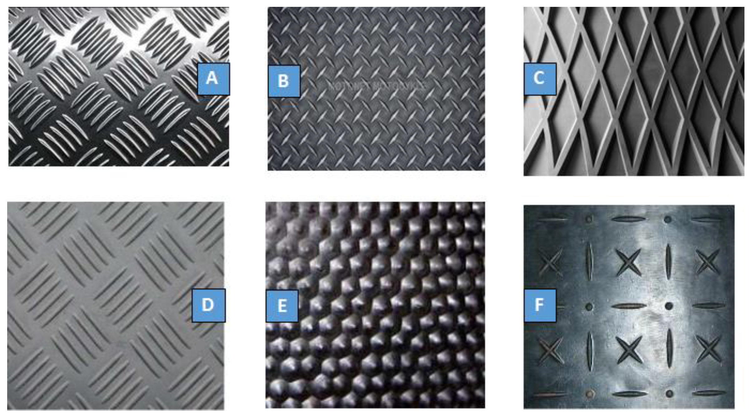
Very often, tread plates are used in structures where increased friction is important. They are made of plain steel, stainless steel or aluminium with a rolled-off pattern on one side. Anti-slip properties are achieved by an irregular surface. There are multiple tread patterns in use; the most common are single, double and quintuple tears and single round or square protrusions. Tread plate is widely used as a lightweight construction material to make lightweight, durable and anti-slip floors, landings and stairs. They are widely used in transportation, shipbuilding, construction,
Figure 5.
Another way to increase the coefficient of friction is to use abrasives, which are defined as materials such as dusts and powders with small grain size that are bonded to paper, cardboard or fabric to increase the coefficient of friction. They are applied in the production of anti-slip tapes or abrasive papers. Examples of materials include electrocorundum, silicon carbide, metal powders and dusts [
30,
31,
32,
33,
34].
In addition, elastomers in the form of rubber, natural rubber and synthetic rubber have excellent anti-slip properties. These are polymers that deform under an applied force and return to their original shape when the load is removed. These plastics are suitable for industrial use only after the vulcanization process, during which they are cross-linked under the influence of sulphur and obtain a spatial structure. Depending on the addition of sulphur, soft rubber (2–4%), medium rubber or hard rubber—ebonite (30–50%) is obtained. Apart from the main component, the following substances are added to the rubber to influence the properties of elastomers obtained: fillers (carbon black, quartz flour, kaolin); dyes; plasticizers (extend the range of the product’s operating temperature); stabilizers (prevent the plastic from decomposition under the influence of light, temperature and oxygen); electrostatic agents (reduce the attraction of dusts by the product); lubricants (give the smoothness and shine, facilitate demoulding); softeners [
35].
The most commonly used synthetic rubbers are polybutadiene and polysoprene as they have properties most similar to natural rubber. Most elastomers have good anti-slip and adhesion properties and are often used in this type of solutions. Depending on the desired effects, a type of rubber that has the required properties may be chosen or the properties of elastomers may be precisely described according to Freunderberg.
In addition, there is also tread rubber, which combines the anti-slip properties of smooth rubber plates and the treads further improving these properties. The ease of moulding rubber allows to use numerous different tread patterns. Such rubber is used, among others, to produce doormats and car mats, rubber floors in stables, anti-slip tapes stuck, e.g., on stairs.
Table 1 illustrates the basic tread patterns on the market.
Coated paper pads are used in logistics systems because they stabilize the load and allow for stacking of successive layers on the pallet. They are reusable and an alternative to stretch film; available in weights: 65 [g/m
2], 110 [g/m
2] and 270 [g/m
2], based on [
41].
Anti-slip mats are used to secure load during transport. They can be used as spacers between layers of load or as a backing for a pallet in transport. They are reusable and their coefficient of friction is µ = 0.7–0.8.
Abrafol anti-slip bags are made of plastic; they work together and stabilize the load when tilted. The bags are waterproof and retain their properties against humidity, dust and cold temperatures. They are recyclable and reusable.
GrippFix is a liquid viscous substance that increases load adhesion. It is a patented water-soluble substance. GrippFix can be applied to paper, cardboard, and plastic wrapped loads. It is applied in small quantities to the load before palletizing. During transport the load retains its anti-slip properties; during and after depalletization GrippFix leaves no residue.
ForkGrips is a patented solution. It is an elastomer pad that is placed on the end of the fork. It is a helpful tool when unloading goods. It was designed to pull the load with the fork tip to the edge of the semi-trailer without worker intervention and manual handling of the load or using chains or ropes.
Tread plate pad in the form of protrusions on the back part of the fork—SJF Material Handling Equipment.
The company VETTER Polska Sp. z o.o. has its forks directly covered with an anti-slip material; in this case polyurethane or Gripp Fix material. Gripp Fix is a patented anti-slip, water-soluble substance that prevents the load from sliding horizontally.
Emporo—protective anti-slip pads made of plastic. Provide load and fork protection. They protect the load from slipping off, dampen noise and are wear-resistant. The “state of the art” carried out gives rise to the summary in the form of
Figure 6; the reconnaissance carried out in the patent databases is not included as this is contained in the patent description [
42].
Few people know about it but very often companies lubricate bags with a thin layer of glue or paraffin (sometimes with additives increasing friction) when forming the transport load on a pallet. Such practices strongly hinder the implementation of EU environmental regulations [
43], because plastic bags made of LDP (single or multilayer) with adhesive are much more difficult to reuse.
4. Concept, Computational Model, Prototype
The attachment, mounted on a lift arm of a forklift truck, is made of a channel-shaped profile locally closed with plates attached to it, with an anti-slip layer in the middle of the profile, one end of the eye wall of the profile tapering towards its leading edge according to the patent; it is characterized in that in the middle of the profile, in the area of its end in which the side walls taper, an opening is formed, in which a locking device equipped with a ratchet spring is embedded. The pawl lock has the form of a pawl that is pendulum-fixed on a pin mounted on the side walls of the profile, which is spring-loaded and supported on the other end against a plate closing the profile and equipped with a tongue located at its bottom edge and limiting the range of retraction of the pawl from the profile web. The anti-slip layer is in the form of an elastomer in which corundum grains are embedded. The anti-slip layer can be dedicated to individual needs. The advantage of this solution is that the anti-slip pad can be retrofitted with an additional mechanical load slide lock. In addition, the pawl lock can be used as a gripper to move standing pallets of load, for example when unloading trailers, whereby the creation of a mechanical pawl lock does not impede fork insertion under the pallet. Features of the construction with anti-slip surface:
- −
increased load cushioning,
- −
vibration reduction,
- −
increased load safety as a result of the pallet slipping off the forks,
- −
increased load handling speed,
- −
reduced truck travel times,
- −
electrostatic properties,
- −
drainage grooves (e.g., working in the rain)
- −
wear protection for forks,
- −
lower sound emissions,
- −
the pallet locking structure can be used as a hook to pull the pallet from hard to reach places.
Application area for forks with anti-slip surface:
- −
loads that require a higher level of security during handling (e.g., porcelain, artwork in museums),
- −
high-value loads (e.g., electronic equipment),
- −
places at risk from electricity (power plants),
- −
loads requiring additional protection (glass sheets, metal sheets),
- −
locations with relatively large distances covered by the trucks (e.g., logistics centers, cooperating companies in special economic zones, companies with large surface areas),
- −
maneuvering areas with damaged and uneven surfaces or with numerous driveways and exits.
4.1. Preliminary Concept Evaluation
In order to initially evaluate the concept of load damage reduction, a computational model was used to reflect the actual load of a load unit that is on the forks of a forklift:
- −
a pallet on the forks of a forklift truck is subjected to a gravitational force (equal to the product of the mass and gravitational acceleration);
- −
when driving around a curve (with a given R [m]), there is a centrifugal force whose value increases in square speed. In the model, the value of the centrifugal force that does not (yet) cause the pallet to move laterally on the forks of the forklift corresponds to the maximum speed on the curve (the so-called operating speed);
- −
Braking force in the model (FH)—it was assumed that FH = const [N]). Since braking is closely related to the force of inertia which counteracts the braking of the forklift , then the forklift moves in decelerated motion. The negative acceleration acting on the vehicle is called braking deceleration, at which there is a risk of the load slipping (2) and/or tipping off the fork carriage (3).
By analysing these cases (
Figure 7), it is possible to determine (4) the values of braking deceleration
and curve speed. The following load dimensions were assumed for calculations: 1.0 [m] 1.2 [m].
From which the formula for deceleration can be derived:
Simulation calculations were performed using Matlab-Simulink, which was presented at the International Conference on Computer Aided Engineering. After conference discussions and reviews, [
44] (indexed on WOS) was published.
This model does not allow, admittedly, to assess the damage to the load, but the information obtained about the increase in forklift performance calculated according to [
45] in relation to the standard solution determined the financing of subsequent works/steps in the design and testing of the prototype in terms of damage as in
Section 4.2 and subsequent papers.
4.2. FEM Calculations
Structural design of an anti-slip pad in SolidWorks,
Figure 8. In addition, the finite element method, which is used to solve systems of differential equations, was further used. SolidWorks model drawings of fork pads with anti-slip protection are added below. Based on the 3D model of the device, the analysis was carried out and the mentioned model was converted into technical drawings as in the publication [
46]. The assumption on which the analysis was based was to perform a strength test of the laden pallet pressure on the physical locking element. The assumed pressure on the lock is 10 [KN].
4.3. Strength Analysis
Below is a strength analysis of an anti-slip pad for a forklift lift arm performed in SolidWorks Simulation. The element in
Figure 9 was analysed. Model assumptions:
Type of analysis—Static analysis
Model type—isotropic linear elastic
Units—SI-N/mm2 (Mpa)
Acting force—10,000 N
Material name—Cold bent steel from hot rolled strip.
Material properties:
Coefficient of elasticity—205,000 N/mm2
Poisson’s ratio—0.29
Shear stress ratio—8000 N/mm2
Specific mass—7870 kg/m3
Tensile strength—424 N/mm2
Yield strength—314 N/mm2
Thermal expansion coefficient—1.17 × 10⁻⁵ K
Thermal conductivity coefficient—51.9 W/(m*K)
Specific heat—1386 J/(kg*K)
Figure 9B shows where the fixtures are applied and where the forces act.
Figure 9.
(A)—Pallet lock; (B)—Location of fixtures (green) and location of force application (purple); (C)—Pallet lock solid mesh; (D)—Reduced stresses according to Mises; (E)—Displacement analysis; (F)—Deformation analysis; (G)—Fatigue reading chart; (H) — Static analysis in FEM.
Figure 9.
(A)—Pallet lock; (B)—Location of fixtures (green) and location of force application (purple); (C)—Pallet lock solid mesh; (D)—Reduced stresses according to Mises; (E)—Displacement analysis; (F)—Deformation analysis; (G)—Fatigue reading chart; (H) — Static analysis in FEM.
From the above analysis, it can be seen that the force acting on the element does not have much effect on the strength. SolidWorks generated the mesh of the solid according to the following guidelines:
Mesh type—solid
Jacobian points—4
Element size—2.8431 mm
Mesh quality—high
Total number of nodes—26,121
Total number of elements—15,282
Mises reduced stress test:
- 7.
min. 3947.98 N/mm2—node 19,383
- 8.
max. 9.29249 × 10⁷ N/mm2—node 24,144
Displacements:
- 9.
min. 0—node 36
- 10.
max 0.0123253—node 20,517
Displacement analysis:
Deformation analysis:
Type: equivalent deformations
min. 2.33007 × 10⁻⁸—element 13,411
max. 0.00330626—element 14,454
Figure 10 shows an exploded view of the fork pad model based on which the forklift attachment prototype was made.
As a result of the analysis of scientific literature and studies related to the described research problem, it is concluded that the proposed solution meets the requirements of the anti-slip design locking the pallet.
4.4. Prototype
The above model was tested under operating conditions in a logistics center (warehouse) and indeed showed increased frictional properties at the contact points between the pads and the pallet surface. The prototype components were made from cold bent steel from hot rolled strip. The surface of the model was coated with elastomer, which was the binder for the corundum, since both materials used have very good frictional properties. In addition, this polyurethane elastomer shows good adhesion, elasticity, temperature resistance, abrasion resistance and chemical aging resistance. Polyurethane, despite its anti-slip properties, is used as a binder for corundum, which further enhances the frictional and anti-slip properties. Additionally, the elastomer-free surface was painted.
Figure 11A–E documents the model development process.
Figure 12A–C shows the process of applying the anti-slip layer using a special mould. The use of the mould allows the user to modify the anti-slip layer on their own and apply it to the fork arm of the forklift. The anti-slip layer has shock absorbing properties for the load on forklift forks. Currently, the method of chemical composition and substance selection is covered by a separate patent proceeding before the Polish Patent Office.
The use of polymer as a binder for the friction material has no environmental footprint because polymer chains are strong enough that cleaning the polymer in recycling plants, on screens—from additional friction materials—it makes the material (polymer) reusable in plastics processing There is no complication of “zero waste” processes.
5. Prototype Testing
Patent proceedings before the Polish Patent Office and commercialization of the invention required performance of works confirming the efficiency improvement according to ISO 50,001 [
47] claimed by means of engineering experience and modeling results (for reference values, see
Section 5.1 of the paper), where an increase in forklift efficiency by 12% in relation to existing industry solutions was obtained.
The main subject of the paper is pallet damage. In the following section, work was done to verify the utility of patent in reducing pallet damage. Tests were performed as below for two cases Test-1
Section 5.1 and Test-2
Section 5.2.
Based on own research, the following damage assessment method was adopted: the forklift will perform the work cycles according to VDI 2198. As is well known, pallets in logistics centers are registered in the WMS system [
48]. Based on the regulations of the GS-1 international organization, pallets were tagged with the SSCC information vector for the duration of the study [
49]. Pallets were assigned an individual number as part of the research process. Hence, the history of pallets was known and recorded in a WMS-independent database system by tagging them with an information vector (
Figure 13). Possible solutions were also analyzed among the effects of works [
50,
51,
52].
The information vector data was expressed in GS-1 128 code symbology, in the “B” coding set, using the (IZ) [
53] standard application identifier. A thermal transfer printer with a 125 KHz RFID antenna was used for printing, and barcode label printing was implemented in conjunction with RFID tag programming [
54,
55]. The label was placed on the pallets. A readout with a scanner and RFID reader was hence possible.
Pallet damage was determined according to [
56]. This type of evaluation methodology worked well in an unpublished raport and was perfectly evaluated by a world-renowned company in the logistics industry.
Test results were performed for polyurethane 75Sha (manufacturer company: Chester Elastomer) (
Figure 12) because it is available (popular) on the market and widely used in industry. The installed prototype on the forklift used in the study is presented in
Figure 14.
5.1. Test-1
The test pallets were varied; they were new or had an unknown history as to their transport cycles, so an initial pre-loading study was performed; it consisted of confirming the manufacturer’s certification for new pallets and approving used pallets according to European Standard 13698,
Figure 15A–E,G.
The prototype tests were performed for the duty cycle according to VDI2198 & (
Table 2) for loads from the groups: A, C, G, H with varying loads: 300, 500, 700 kg.
After testing in a logistics center with a turnover of 450,000 europallets per year, a database was created for 90 selected pallet units containing the test results
Figure 16. Some results that can be published are shown below.
The tests did not consider operator fatigue or the visibility of the pallet from the forklift operator’s seat [
57], which depends on the forklift model (even when equipped with a set of cameras on the forks of the forklift. The camera set is installed as standard by forklift truck manufacturers from 6.5 [m] lift height). These issues are further discussed in papers [
58,
59].
The purpose of the tests was to verify whether the use of the developed prototype actually reduces the amount of damage.
Certain groups of pallets were stacked in an “overlapping” manner (characterized by one pallet coming into contact tightly with another, nearly snagging), which occurs when a mechanism is used to laterally move the pallet through the fork mechanism of a forklift truck. The pawl lock (
Figure 14, especially “B”, “E”) acts as a gripper, used for moving standing pallets with load. For example, when unloading semi-trailers, whereby the creation of a mechanical lock in the form of a pawl does not impede the insertion of the fork under the pallet.
5.2. Test-2
Test-2 was performed at a manufacturer of large-area PUR panels in Poland, which are produced from properly prepared materials on an automated production line. The manufacturer noted complaints consisting of the occurrence of microdents, scratches (the damage is micro dents and scratches that are clearly visible only after mounting the panel on a wall in good lighting of a sunny day). They caused not only financial losses of the manufacturer but also dissatisfaction of the crew employed in the production, which despite many efforts of care and quality met with complaints.
A technology audit led to the development of a suitable material with both frictional and cushioning properties (as in
Figure 12) and mounting of the thus prepared invention on forklifts (
Figure 17), which resulted in reduction of vibrations coming from the interaction of the forklift wheel with the maneuvering yard surface usunięto odand determination of appropriate maximum values of the forklift speed based on the model.
Load damage not only depends on properly designed forks, performance of internal handling staff and packaging.
Figure 17 illustrates the loading of a truck semi-trailer; it is critical to plan the load so that there is no shifting of the load on the trailer, even if the trailer is extremely tilted.
The panels are usually delivered to customers at the construction site with poor quality access roads, and the unloading of the panels from the semi-trailer at the construction site is carried out hastily.
The information obtained and practices observed led to the development of paper [
60].
In some cases, achieving the expected improvement in product quality following a point action—such as the use of [
61]—requires integration with activities throughout the supply chain or process sequence (analogous to
Figure 1).
6. Conclusions
Apart from its innovative and applicational value, the paper has a scientific merit: the most common friction coefficients given in the tables are for the friction pair: wood—steel (which the fact is frequently overseen by engineers). In the analyzed case, the friction pair is: the material of the pallet (KLT boxes, packaging) and the anti-slip layer on the anti-slip pad. Individual coefficients of friction for each friction pair were experimentally determined in the laboratory. These friction coefficients were included in the numerical calculations in SolidWorks (constraint definition) where the structure was calculated and optimized. The same applied to calculation of the traction parameters of the forklift, carried out using Matlab—Simulink.
The nature of the forklift operation illustrated in
Figure 4 which that the change of the transport corridor in the warehouse requires the following actions:—reducing the speed of the forklift—moving in a curve to the left or right—accelerating the forklift. The use of an anti-slip pad may require a barely perceptible reduction in speed during the movement of the forklift in a curve, thus limiting unnecessary activities such as braking, driving at a safe speed or accelerating the forklift to the maximum speed. Braking, driving at the minimum speed and accelerating the forklift all affect the total energy consumption of the forklift. Reducing these parameters may bring energy consumption down. The movement of the forklift in the curve is analogous. In the contemporary literature of this field one may read that the maximum and cost-effective rectilinear travel distance for a forklift truck is about 100 [m] (it is advisable not to exceed it and use conveyors instead).
- 1
A forklift fork attachment can be used on forklifts to increase both forklift efficiency and reduce load damage. This was confirmed by a study in a logistics center in Poland, which proved that the use of has a positive effect on reducing pallet damage due to shifting (test-1) and due to excessive vibration (test-2).
- 2
The methodology for calculating the forces according to relation (1)–(4) in
Section 4.1 of the paper requires the use of the information found on the forks (
Figure 3) and transport pallet (
Figure 2J). The methodology is generic and does not require additional laboratory testing, hence the opportunity for widespread implementation in companies.
- 3
The efficiency of the forklift with the attachment was confirmed in an ISO 50,001 test [
62]; it was 12% more than known solutions. The authors have documented research experience in the application of the ISO 50,001 standard through the presentation of the results of their own research at a conference and the publication [
63] (Web of Science).
For specific working conditions in the logistics center, defined by the material from which the pallet is made and the traction characteristics of the forklift—it is planned to make an advisory system that will support the work of managerial staff and forklift operators, with the aim of reducing damage to cargo and increasing the efficiency of transport processes.
The fork for the forklift is a structural part, made of steel. Further work should be aimed at the use of composites and materials safe for the environment [
64].
The design of the designed overlay has been optimized and the topic can be considered closed. Unfortunately, this is not the case with the anti-slip layer (increasing the coefficient of friction). The technological process, as shown in
Figure 12, is difficult and requires experience. This is not a problem with several forklifts. In the case of a logistics center and a fleet of forklifts, this can already be highly demanding. Therefore, it is planned to look for a better technology in the near future.
Author Contributions
Methodology, conceptualization, investigation, data curation, writing—review & editing, P.Z.; methodology, investigation, formal analysis, writing—original draft, validation, E.D.; resources, investigation, formal analysis: T.R.; investigation, software, visualization, project administration, visualization, project administration. All authors have read and agreed to the published version of the manuscript.
Funding
This research received no external funding.
Institutional Review Board Statement
Not applicable.
Informed Consent Statement
Not applicable.
Data Availability Statement
Not applicable.
Acknowledgments
I wish to thank the following individuals and institutions: co-authors of the invention for their commitment and hard work on the project; Rector of the Wrocław University of Technology J.M., who, in accordance with the recommendation of the Committee for Technology Transfer, decided to allocate the research result “Anti-slip locking of pallet load” for commercialization; The Wroclaw Centre for Technology Transfer (WCTT) of Wroclaw University of Science and Technology, for funding the patent procedure before the Polish Patent Office and for financing and organizing the photo shoot.
Conflicts of Interest
The authors declare that they have no known competing financial interests or personal relationships that could have influenced the work reported in this study.
References
- Van Nunen, K.; Swuste, P.; Reniers, G.; Paltrinieri, N.; Aneziris, O.; Ponnet, K. Improving pallet mover safety in the manufacturing industry: A bow-tie analysis of accident scenarios. Materials 2018, 11, 1955. [Google Scholar] [CrossRef] [PubMed] [Green Version]
- Liu, B.; Liu, T.; Lin, Y.; Zhao, J. An aircraft pallet damage monitoring method based on damage subarea identification and probability-based diagnostic imaging. J. Adv. Transp. 2019, 2019, 12. [Google Scholar] [CrossRef]
- Singh, P.; Singh, J.; Antle, J.; Topper, E.; Grewal, G. Load securement and packaging methods to reduce risk of damage and personal injury for cargo freight in truck, container and intermodal shipments. J. Appl. Packag. Res. 2014, 6, 6. [Google Scholar]
- Vlkovský, M.; Ivanuša, T.; Neumann, V.; Foltin, P.; Vlachová, H. Optimizating cargo security during transport using dataloggers. J. Transp. Secur. 2017, 10, 63–71. [Google Scholar] [CrossRef]
- Mazur, P.G.; Lee, N.S.; Schoder, D. Integration of Physical Simulations in Static Stability Assessments for Pallet Loading in Air Cargo. In Proceedings of the 2020 Winter Simulation Conference (WSC), Orlando, FL, USA, 14–18 December 2020; IEEE: Piscataway, NJ, USA; pp. 1312–1323. [Google Scholar] [CrossRef]
- Oktaviani, N.; Yadia, Z.A.; Nasution, N.; Veronica, V. How to reduce cargo damage? In Proceedings of the Conference on Global Research on Sustainable Transport (GROST 2017), Jakarta, Indonesia, 22–23 November 2017. [Google Scholar] [CrossRef] [Green Version]
- Gružauskas, V.; Baskutis, S.; Navickas, V. Minimizing the trade-off between sustainability and cost effective performance by using autonomous vehicles. J. Clean. Prod. Lond. Elsevier 2018, 184, 709–717. [Google Scholar] [CrossRef]
- Nawrocki, W.; Stryjski, R.; Woźniak, W.; Jakubowski, J. Improving the Quality of Manufacturing Processes in Toyota Motor Manufacturin, Poland. In Proceedings of the 31st International Business Information Management Association Conference—IBIMA, Milan, Italy, 25–26 April 2018; pp. 5931–5945. [Google Scholar]
- Woźniak, W.; Nawrocki, W.; Stryjski, R.; Jakubowski, J. Identification and Reduction of Product Defects in Mass Production at Toyota Motor Manufacturing, Poland. In Proceedings of the 30th International Business Information Management Association Conference—IBIMA, Madrid, Spain, 8–9 November 2017; pp. 4774–4782. [Google Scholar]
- Pawlewski, P.; Golinska, P.; Fertsch, M.; Trujillo, J.A.; Pasek, Z.J. Multiagent approach for supply chain integration by distributed production planning, scheduling and control system. In International Symposium on Distributed Computing and Artificial Intelligence 2008 (DCAI 2008); Springer: Berlin/Heidelberg, Germany, 2008; pp. 29–37. [Google Scholar] [CrossRef]
- Golinska, P.; Hajdul, M. Multi-agent coordination mechanism of virtual supply chain. In KES International Symposium on Agent and Multi-Agent Systems: Technologies and Applications; Springer: Berlin/Heidelberg, Germany, 2011; pp. 620–629. [Google Scholar] [CrossRef]
- Hanson, R.; Finnsgård, C. Impact of unit load size on in-plant materials supply efficiency. Int. J. Prod. Econ. 2014, 147, 46–52. [Google Scholar] [CrossRef]
- Guo, X.; Yu, Y.; De Koster, R.B. Impact of required storage space on storage policy performance in a unit-load warehouse. Int. J. Prod. Res. 2016, 54, 2405–2418. [Google Scholar] [CrossRef]
- PN-EN 13183-1:2004. Lumber piece moisture - Part 1: Determination of moisture content by dry weighing. Poland, 2004.
- Clayton, A.P.; Horvath, L.; Bouldin, J.; Gething, B. Investigation of the effect of column stacked corrugated boxes on load bridging using partial four-way stringer class wooden pallets. Packag. Technol. Sci. 2019, 32, 423–439. [Google Scholar] [CrossRef]
- Phanthanousy, S. The Effect of the Stiffness of Unit Load Components on Pallet Deflection and Box Compression Strength. Doctoral Dissertation, Virginia Tech., Blacksburg, VA, USA, 2017. Available online: http://hdl.handle.net/10919/86203 (accessed on 11 December 2021).
- ISO 16106:2006. Packaging—Packaging for the Transport of Hazardous Materials—Packaging for HAZARDOUS materials, Large Bulk Containers (IBCs) and Large Packaging—Guidelines for the Application of ISO 9001; ISO: Geneva, Switzerland, 2006. [Google Scholar]
- Kočí, V. Comparisons of environmental impacts between wood and plastic transport pallets. Sci. Total Environ. 2019, 686, 514–528. [Google Scholar] [CrossRef]
- Ghalehkhondabi, I.; Masel, D.T. Storage allocation in a warehouse based on the forklifts fleet availability. J. Algorithms Comput. Technol. 2018, 12, 127–135. [Google Scholar] [CrossRef]
- Li, J.; Wang, B.J.; Zhou, J. The reliability-based design and optimization procedures for a heavy-duty pallet system. Adv. Mech. Eng. Fail. Anal. 2018, 10, 1687814017751752. [Google Scholar] [CrossRef]
- ISO 2330. Fork-Lift Trucks—Fork Arms—Technical Characteristics and Testing; ISO: Geneva, Switzerland, 1995. [Google Scholar]
- Pantazopoulos, G.; Vazdirvanidis, A.; Rikos, A.; Toulfatzis, A. Analysis of abnormal fatigue failure of forklift forks. Case Stud. Eng. Fail. Anal. 2014, 2, 9–14. [Google Scholar] [CrossRef] [Green Version]
- Gubeljak, N.; Zerbst, U.; Predan, J.; Oblak, M. Application of the european SINTAP procedure to the failure analysis of a broken forklift. Eng. Fail. Anal. 2004, 11, 33–47. [Google Scholar] [CrossRef]
- Massone, J.M.; Boeri, R.E. Failure of forklift forks. Eng. Fail. Anal. 2010, 17, 1062–1068. [Google Scholar] [CrossRef]
- Rebelle, J.; Mistrot, P.; Poirot, R. Development and validation of a numerical model for predicting forklift truck tip-over. Veh. Syst. Dyn. 2009, 47, 771–804. [Google Scholar] [CrossRef]
- Larsson, T.J.; Rechnitzer, G. Forklift trucks—Analysis of severe and fatal occupational injuries, critical incidents and priorities for prevention. Saf. Sci. 1994, 17, 275–289. [Google Scholar] [CrossRef]
- Xia, G.; Li, J.; Tang, X.; Zhao, L.; Sun, B. Layered control of forklift lateral stability based on Takagi—Sugenofuzzy neural network. Proc. Inst. Mech. Eng. Part D J. Automob. Eng. 2021, 235, 1767–1780. [Google Scholar] [CrossRef]
- Figueiredo, M.V.; Oliveira, F.M.F.; Goncalves, J.P.M.; de Castro, P.M.S.T.; Fernandes, A.A. Fracture analysis of forks of a heavy duty lift truck. Eng. Fail. Anal. 2001, 8, 411–421. [Google Scholar] [CrossRef]
- Rasyid, R.A.; Katias, P. Exploring The Causes of The Finished Products Damage. In Proceedings International Conference Technopreneur and Education 2018, Volume 1, No 1; ICTE: Surabaya, Indonesia, 2019. [Google Scholar]
- Jamroziak, K.; Roik, T.; Gavrish, O.; Vitsiuk, I.; Lesiuk, G.; Correia, J.A.F.O.; De Jesus, A. Improved manufacturing performance of a new antifriction composite parts based on copper. Elsevier Eng. Fail. Anal. 2018, 91, 225–233. [Google Scholar] [CrossRef]
- Jamroziak, K.; Roik, T. New Antifriction Composite Materials Based On Tool Steel Grinding Waste. WIT Trans. Eng. Sci. 2019, 124, 151–159. [Google Scholar] [CrossRef] [Green Version]
- Kurzawa, A.; Roik, T.; Gavrysh, O.; Vitsiuk, I.; Bocian, M.; Pyka, D.; Zajac, P.; Jamroziak, K. Friction mechanism features of the nickel-based composite antifriction materials at high temperatures. Coatings 2020, 10, 454. [Google Scholar] [CrossRef]
- Jamroziak, K.; Roik, T. Friction Films and Their Influence on the Antifriction Properties of New High-Temperature Nickel Composites. In Lecture Notes in Mechanical Engineering, Proceedings of the 8th International Conference on Fracture Fatigue and Wear, FFW-2019, Bruges, Belgium, 13–14 July 2020; Abdel, W.M., Ed.; Springer: Singapore, 2020; pp. 601–611. [Google Scholar] [CrossRef]
- Kosobudzki, M.; Jamroziak, K.; Bocian, M.; Kotowski, P.; Zając, P. The analysis of structure of the repaired freight wagon. In AIP Conference Proceedings; AIP Publishing LLC: Melville, NY, USA, 2018; Volume 2029, No. 1; p. 020030. [Google Scholar] [CrossRef]
- Balsys, K.; Eidukas, D.; Marma, A.; Valinevičius, A.; Žilys, M. Systems of transport route development. Electron. Electr. Eng. 2017, 3, 17–22. [Google Scholar]
- Navickas, V.; Gružauskas, V.; Baskutis, S. The food industry’s supply chain’s effectivity management: Small markets’ case. Acta Oeconomica Univ. Selye 2015, 4, 149–161. [Google Scholar]
- Crainic, T.; Perboli, G.; Rosano, M. Simulation of intermodal freight transportation systems: A taxonomy. Eur. J. Oper. Res. 2018, 2, 401–418. [Google Scholar] [CrossRef]
- Fulzele, V.; Shankar, R.; Choudhary, D. A model for the selection of transportation modes in the context of sustainable freight transportation. Ind. Manag. Data Syst. 2019, 119, 1764–1784. [Google Scholar] [CrossRef]
- Kelle, P.; Song, J.; Jin, M.; Schneider, H.; Claypool, C. Evaluation of operational and environmental sustainability tradeoffs in multimodal freight transportation planning. Int. J. Prod. Econ. 2019, 209, 411–420. [Google Scholar] [CrossRef]
- Jamroziak, K.; Roik, T. Structure and Properties of the New Antifriction Composite Materials for High-Temperature Friction Units. In Lecture Notes in Mechanical Engineering, Proceedings of the 7th International Conference on Fracture Fatigue and Wear, FFW-2018, Ghent, Belgium, 9–10 July 2018; Abdel, W.M., Ed.; Springer: Singapore, 2019; pp. 628–637. [Google Scholar] [CrossRef]
- Navickas, V.; Baskutis, S.; Gružauskas, V. Supply chain in small market food industry: Increasing competitive advantage. Int. J. Manag. Theory Appl. (IREMAN) Napoli Praise Worthy Prize 2015, 3, 1–5. [Google Scholar]
- Wroclaw University of Science and Technology. Anti-Slip Overlay for Forklift Lifting Arm: Int. Cl. B66F 9/12, B66F 9/18. Poland Patent No. 69203, 30 June 2017. [Google Scholar]
- Communication from the Commission to the European Parliament, the Council, the European Economic and Social Committee and the Committee of the Regions towards a Circular Economy: A Zero Waste Programme for Europe. Available online: https://eur-lex.europa.eu/legal-content/EN/TXT/?uri=celex%3A52014DC0398 (accessed on 11 December 2021).
- Zajac, P.; Skorupski, P. Modeling of the Energy Consumption of a Forklift Truck Using the Matlab Simulink System. In Proceedings of the International Conference on Computer Aided Engineering 2018, Wrocław, Poland, 20–23 June 2018; pp. 851–857. [Google Scholar] [CrossRef]
- VDI 2198. VDI Manual Technical Logistics—Volume 2: Industrial Trucks; Engl. VDI-Gesellschaft Produktion und Logistik: Düsseldorf, Germany, 2019. [Google Scholar]
- Jakubowski, J.; Woźniak, W.; Stryjski, R. The Use of 3D Scanning and Measurements, as Modern Tools in the Management of Quality. In Proceedings of the 31st International Business Information Management Association Conference—IBIMA, Milan, Italy, 25–26 April 2018; pp. 5946–5955. [Google Scholar]
- Kurdve, M.; Zackrisson, M.; Wiktorsson, M.; Harlin, U. Lean and green integration into production system models—Experiences from Swedish industry. J. Clean. Prod. 2014, 85, 180–190. [Google Scholar] [CrossRef]
- Navickas, V.; Baskutis, S.; Gruzauskas, V.; Kabasinskas, A. Warehouses consolidation in the logistic clusters: Food industry’s case. Pol. J. Manag. Stud. 2016, 14, 174–182. [Google Scholar] [CrossRef]
- Zajac, P.; Kowalczyk, L. Comprehensive service of conference participants using automatic identification. In Proceedings of the 23rd International Conference ENGINEERING MECHANICS 2017, Svratka, Czech Republic, 15–18 May 2017; Available online: https://www.engmech.cz/2017/im/doc/EM2017_proceedings_all.pdf (accessed on 11 December 2021).
- Dragašius, E.; Eidukynas, D.; Jūrėnas, V.; Mažeika, D.; Galdikas, M.; Mystkowski, A.; Mystkowska, J. Piezoelectric transducer-based diagnostic system for composite structure health monitoring. Sensors 2021, 21, 253. [Google Scholar] [CrossRef]
- Vėžys, J.; Mažeika, D.; Kandrotaitė, J.R.; Dragašius, E.; Kilikevičius, A.; Korobko, E. Sedimentation influence on magnetorheological brake torque moment. Strength Mater. 2018, 50, 357–367. [Google Scholar] [CrossRef]
- Dragašius, E.; Eidukynas, D.; Mažeika, D.; Mystkowski, A.; Ažubalis, M. The strength investigation of the composite material with implanted sensors. Mechanics 2015, 21, 23–27. [Google Scholar] [CrossRef] [Green Version]
- Zajac, P.; Kwasniowski, S. Reliability of automatic identification systems in logistics systems. In Proceedings of the 23rd International conference engineering mechanics, Svratka, Czech Republic, 15–18 May 2017; pp. 1098–2021. Available online: https://www.engmech.cz/2017/im/doc/EM2017_proceedings_all.pdf (accessed on 11 December 2021).
- Zajac, P.; Kwasniowski, S. The reliability problems of reading RFID tags in logistics warehouse systems. In MATEC Web of Conferences; EDP Sciences: Les Ulis, France, 2017; Volume 112, p. 05012. [Google Scholar] [CrossRef] [Green Version]
- Zajac, P.; Skoczynski, W.; Romanowicz, W. Studies of Properties of RFID Tags Used in Mechatronic and Logistic Systems. ISBN 978-80-87012-71-0. 2019; Available online: https://www.engmech.cz/im/proceedings/show_p/2019/415 (accessed on 11 December 2021).
- PN-EN 13698-1: 2005. Pallet requirements - Part 1: Manufacturing requirements for 800 mm x 1200 mm flat wooden pallets. 2003.
- Marfuah, M.E.S. Decreasing of Work Accident by Fmea (Failure Mode and Effect Analysis) Tools and Jsa (Job Safety Analysis) Method. Ph.D. Thesis, President University, West Java, Indonesia, 2019. [Google Scholar]
- Bergamasco, M.; Perotti, S.; Avizzano, C.A.; Angerilli, M.; Carrozzino, M.; Ruffaldi, E. Forklift truck simulator for training in industrial environment. In Proceedings of the 2005 IEEE Conference on Emerging Technologies and Factory Automation, Catania, Italy, 19–22 September 2005. [Google Scholar] [CrossRef]
- Alnahhal, M.; Ahrens, D.A. Simulation-Based System for Calculating Optimal Numbers of Forklift Drivers in Industrial Plants. Bavar. J. Appl. Sci. 2018, 4, 354–369. [Google Scholar] [CrossRef]
- Zajac, P.; Rozic, T. Energy consumption of forklift versus standards, effects of their use and expectations. Energy 2022, 239, 122187. [Google Scholar] [CrossRef]
- Gardas, B.B.; Raut, R.D.; Narkhede, B. Identifying critical success factors to facilitate reusable plastic packaging towards sustainable supply chain management. J. Environ. Manag. 2019, 236, 81–92. [Google Scholar] [CrossRef] [PubMed]
- ISO 50001. Energy Management Systems; ISO: Geneva, Switzerland, 2018. [Google Scholar]
- Zając, P. Evaluation of automatic identification systems according to ISO 50001. In International Conference on Automation; Springer: Cham, Switzerland, 2015. [Google Scholar] [CrossRef]
- Bauer, T.; Mandil, G.; Monnier, É.; Zwolinski, P. Design for cascading applications reuse–understandings of an emerging end-of-use strategy and propositions for its implementation. J. Eng. Des. 2021, 32, 140–163. [Google Scholar] [CrossRef]
Figure 1.
Possible damage to load caused by forklift (red arrow—forklift operating area).
Figure 1.
Possible damage to load caused by forklift (red arrow—forklift operating area).
Figure 2.
Damage to the pallets: (A–K) discussed in the text.
Figure 2.
Damage to the pallets: (A–K) discussed in the text.
Figure 3.
(A) Example fork marking: H4067L7—serial number; 232,014—production date; 1500 × 500—fork length and lifting capacity; made in China; (B)—safe pallet location on forks.
Figure 3.
(A) Example fork marking: H4067L7—serial number; 232,014—production date; 1500 × 500—fork length and lifting capacity; made in China; (B)—safe pallet location on forks.
Figure 4.
A model run of a forklift.
Figure 4.
A model run of a forklift.
Figure 5.
Tread plate metal patterns: (A)—Quintuple tear; (B)—Single tear; (C)—Grid; (D)—Quintuple tear; (E)—Protrusions; (F)—Mixed pattern (sometimes referred to as “knurled pattern”).
Figure 5.
Tread plate metal patterns: (A)—Quintuple tear; (B)—Single tear; (C)—Grid; (D)—Quintuple tear; (E)—Protrusions; (F)—Mixed pattern (sometimes referred to as “knurled pattern”).
Figure 6.
Anti-slip and load-stabilizing solutions in logistics.
Figure 6.
Anti-slip and load-stabilizing solutions in logistics.
Figure 7.
Position of the load on the fork carriage of the forklift: slip-off case; tipping case: l is the distance of the center of gravity of the load from the beginning of the fork; h is the height of the center of gravity of the load from the fork.
Figure 7.
Position of the load on the fork carriage of the forklift: slip-off case; tipping case: l is the distance of the center of gravity of the load from the beginning of the fork; h is the height of the center of gravity of the load from the fork.
Figure 8.
(A)–Anti-slip pad installed on the fork of a forklift with an europallet; (B)–Anti-slip pad with lock and composite friction material; (C)–Anti-slip pad installed on the fork of a forklift with an europallet; (D)—Anti-slip pad with lock; (E)—Anti-slip pad with lock; (F)—Anti-slip pad with lock and composite friction material.
Figure 10.
View of fork anti-slip pad: 1—fork core, 2—lock core, 3—rear lock, 4—front pin, 5—spring, 6—rear pin, 7—pad base.
Figure 10.
View of fork anti-slip pad: 1—fork core, 2—lock core, 3—rear lock, 4—front pin, 5—spring, 6—rear pin, 7—pad base.
Figure 11.
(A)—Locking mechanism; (B)—Fork pads in their raw state; (C)—Fork pads—fastening mechanism; (D)—Painted fork pads—locking mechanism; (E)—Ready fork pads.
Figure 11.
(A)—Locking mechanism; (B)—Fork pads in their raw state; (C)—Fork pads—fastening mechanism; (D)—Painted fork pads—locking mechanism; (E)—Ready fork pads.
Figure 12.
Technology of the anti-slip layer: (A)—Mould for casting the elastomer; (B)—Covering the elastomer with corundum; (C)—Mould for casting the elastomer.
Figure 12.
Technology of the anti-slip layer: (A)—Mould for casting the elastomer; (B)—Covering the elastomer with corundum; (C)—Mould for casting the elastomer.
Figure 13.
Sample pallet marking with barcode according to GS-1 128 standard (see content for details).
Figure 13.
Sample pallet marking with barcode according to GS-1 128 standard (see content for details).
Figure 14.
Prototype of pad mounted on a forklift. View of the forklift: (A)—On the right side; (B)—Pawl on the right side; (C)—From the front; (D)—On the left side; (E)—Pawl on the left side.
Figure 14.
Prototype of pad mounted on a forklift. View of the forklift: (A)—On the right side; (B)—Pawl on the right side; (C)—From the front; (D)—On the left side; (E)—Pawl on the left side.
Figure 15.
Illustration of the conducted tests: (A)—Checking the resistance of the pallet to free fall; (B)—Checking the dimensions of the pallet; (C)—Check: new pallet inspection staples/pallet repair authenticity nail nail; (D)—Checking the mandatory inscriptions on the pallet (railway management, manufacturer, hygienic approvals); (E)—Checking the required structural elements of the pallet; (F)—List of pallet research slot; (G)—Illustration of a connection durability test of pallet structural elements (6–10 Nm).
Figure 16.
Number of pallets in the group for damage “without” and “with” anti-slip pad.
Figure 16.
Number of pallets in the group for damage “without” and “with” anti-slip pad.
Figure 17.
Transporting the load with a forklift. (A)—Pallets in the square; (B)—The pallet is transported with a forklift; (C)—The pallet is picked up by a forklift; (D)—View: forklift forks under the pallet; (E)—The forklift puts down the pallet.
Figure 17.
Transporting the load with a forklift. (A)—Pallets in the square; (B)—The pallet is transported with a forklift; (C)—The pallet is picked up by a forklift; (D)—View: forklift forks under the pallet; (E)—The forklift puts down the pallet.
Table 1.
Examples of material treading (knurling).
Table 1.
Examples of material treading (knurling).
| Item | Name | Distributor
/Manufacturer | Material | Construction | Place of Impact |
|---|
| 1 | Anti-slip pads
from coated paper | Logispak [36] | Coated paper | Sheets 74 cm × 114 cm, 80 cm × 119 cm and 100 cm × 119 cm | Pallet—load,
load—load |
| 2 | Anti-slip mats
ASR | Logispak | PE foam,
EVA, PUR | Mat roll: 500 cm × 12.5 cm × 0.8 cm, 500 cm × 25 cm × 0.8 cm, 500 cm × 15 cm × 0.3 mm | Substrate—pallet,
Pallet—load,
load—load, |
| 3 | Anti-slip bags
ABRAFOL | Logispak/Abrafol | Plastic | Bags | Load—load |
| 4 | Gripp-fix | H. Rand GmbH | Water-dispersible substance | Substance available in drums and canisters of various capacities, applied by dispenser or rollers to the load | Load—load |
| 5 | ForkGrips | ForkGrips [37,38] | Rubber | Fork end pads, fully rubberized approx. 20 cm × 10 cm × 1 cm | Truck forks—pallet |
| 6 | Tread plate pads | SJF Materialh
andling [39] | Tread plate | Tread plate pads, mounted on the back of the fork approx. 40 cm. | Truck forks—pallet |
| 7 | Fork with anti-slip lining | Vetter Polska
Sp. z o.o. | Polyurethane,
Gripp Fix | Forks covered with anti-slip material, whole or selected parts | Truck forks—pallet |
| 8 | Protective pads—
anti-slip forks | Emporo [40] | Plastic | Plastic-coated fork pads | Truck forks pallet |
Table 2.
List of parameters to be tested in the damage assessment.
Table 2.
List of parameters to be tested in the damage assessment.
| Structural Elements of the Pallet | Name of the Element | Amount of Elements |
|---|
| board | lower | 1 |
| median1 | 2 |
| longitudinal | 3 |
| median2 | 1 |
| upper intermediate | 2 |
| upper edge | 2 |
| bracket | 9 |
| linear dimension | length | |
| width | |
| height | |
| pallet weight [kg] | | |
| color, discoloration | not included | |
| number of nails (78 pcs) | | |
| thickness of elements: 1 do 8 [mm] (above in the table) | | |
| pallet resistance to free fall | | |
| durability of connections of the structural elements of the pallet | | |
| correct marking on the pallet supports | not included | |
| displacement of the supports | | |
| cracks in the brackets - visibility of the nails | | |
| the presence of mold, soaking with chemical compounds such as paints, oils, adhesives, etc. | not included | |
| assessment of the edges of the lower and upper boards | | |
| board evaluation—chipped off, visibility of nails | | |
| bottom board and top board are broken and the edges diverge | | |
| no bottom or top board—no matter where it is. | | |
| protruding nails above the board plane (no matter where) | | |
| transverse cracks in the board (no matter where) | | |
| Publisher’s Note: MDPI stays neutral with regard to jurisdictional claims in published maps and institutional affiliations. |
© 2021 by the authors. Licensee MDPI, Basel, Switzerland. This article is an open access article distributed under the terms and conditions of the Creative Commons Attribution (CC BY) license (https://creativecommons.org/licenses/by/4.0/).


