Article

Optimization of Sizing and Operation Strategy of Distributed Generation System Based on a Gas Turbine and Renewable Energy

1
Graduate School, Inha University, 100 Inha-ro, Michuhol-Gu, Incheon 22212, Korea
2
Department of Mechanical Engineering, Inha University, 100 Inha-ro, Michuhol-Gu, Incheon 22212, Korea
*
Author to whom correspondence should be addressed.
Energies 2021, 14(24), 8448; https://doi.org/10.3390/en14248448
Submission received: 2 October 2021 / Revised: 5 December 2021 / Accepted: 9 December 2021 / Published: 14 December 2021
(This article belongs to the Section F: Electrical Engineering)

Abstract

:
Optimization of the sizing and operation strategy of a complex energy system requires a large computational burden because of the non-linear nature of the mathematical problem. Accordingly, using a conventional numerical method with only a physics-based model for complete optimization is impractical. To resolve this problem, this paper adopted an optimization method of using an artificial intelligence scheme that combines an artificial neural network (ANN) and a genetic algorithm (GA). Especially, the ANN was constructed based on results from a physics-based model to obtain a large amount of accurate simulation data in a short time frame. A distributed generation (DG) system based on a gas turbine (GT) and renewable energy (RE) was simulated to demonstrate the usefulness of the optimization method. In consideration of the capacity and partial load performance of the GT, the optimization of the sizing and operation strategy of the DG system was performed for three system design scenarios. The optimization criteria were cost-effectiveness and eco-friendliness. The method reduced the calculation time by more than three orders of magnitude while maintaining the same accuracy as the physics-based model. The approach and methodology are expected to be applicable to accurate and fast optimization of various sophisticated energy systems.

1. Introduction

In 2015, the UN declared sustainable development goal 7: “Ensure access to affordable, reliable, sustainable and modern energy for all” [1]. Moreover, with increasing awareness of the climate crisis, renewable energy (RE) is attracting attention. According to a very recent IEA report [2], RE is expected to meet 80% of the total electricity demand growth during the next decade and overtake coal by 2025 as the primary means of producing electricity.
Modern energy must also be supplied to people in remote areas at low costs. In principle, unlike centralized generation, distributed generation (DG) can supply energy to isolated areas with low construction cost and transmission loss [3,4]. Energy paradigms are moving from fossil fuel-based centralized generation to DG, especially those based on RE.
The main drawback of RE is the intermittency of power generation. To compensate for the intermittency, flexible resources need to be installed, such as conventional power generation and energy storage systems (ESSs). However, inappropriate sizing and operation strategies for flexible resources might increase the investment cost of the system or threaten the reliability of energy supply. Therefore, it is essential to optimize the sizing and operational strategy.
To accurately determine the DG sizing and operation strategy, information on the power generation, climatic conditions, and load profile for input data is essential. Especially, many studies proposed optimization methods driven by simplified performance equations or measured power data. Brandoni et al. [5] and Ren et al. [6] used linear programming, and Bischi et al. [7] applied mixed-integer linear programming to optimize a DG system using simplified equations. Li et al. [8] represented a DG system by simple equations, and Tutkun et al. [9] used the measured power data, and they adopted a genetic algorithm (GA) for an optimal DG system. As the DG system has become more complex, improved optimization methods for accurate solutions have appeared in recent years. Moradi et al. [10], Nayanatara et al. [11], Morvaj et al. [12], and HA et al. [13] proposed a hybrid method that combines two different optimization algorithms. Alvarado et al. [14] suggested a technology selection and operation model for optimal selection of a DG system. Falke et al. [15] decomposed a DG optimization problem into three steps to reduce the computational complexity. Vale et al. [16], Golestani et al. [17], and Kampouropoulos et al. [18] predicted extensive power generation data using a regression model, which was then employed for DG optimization. However, the accuracy of these approaches is highly dependent on detailed performance data, which is difficult to collect. Moreover, a regression model trained by the measured data that concentrate on a specific condition can run into an overfitting problem, as shown in Figure 1a.
For this reason, various studies have tried to optimize a DG system using a physics-based model. A physics-based model is reliable because it clearly shows the assumptions and constraints of the problem with accurate implementation of technical performance [19]. Mayer et al. [19], Merei et al. [20], and Ogunjuyigbe et al. [21] conducted optimization studies with a GA using a physics-based model of hybrid energy system. Hou et al. [22] also used a physics-based model and then adopted an epsilon-constraint method as an optimization method. However, due to the strong non-linear nature of the mathematical equations of a physics-based model, a vast computational burden is accompanied inevitably to assure a global optimum [23].
In this study, an artificial intelligence technique that combines a regression model and a metaheuristic algorithm was used to ensure a realistic representation of the operation characteristics of each system component and an accurate global optimum of a DG system with low calculation burden. There is an important difference between the previous studies [16,17,18] and this study. Previous studies used a regression model to generate data to compensate for the insufficient amount of measured data. On the other hand, in this study, to obtain a simulation technique that is accurate and very fast, a regression model was used to mimic a physics-based model. Also, when the regression model is trained by a physics-based model, overfitting can be avoided because it is possible to collect and augment the trained data evenly in a wide range, as shown in Figure 1b.
An artificial neural network (ANN) was adopted for the regression model since it can reflect the non-linear nature of a problem [24]. As an optimization method, a GA was used. Compared with other metaheuristic algorithms, the GA requires the work of ranking solutions, but is well constructed due to earlier introduction and is less prone to premature convergence [25]. Also, since GA can use any kind of fitness function, whether the problem is linear or non-linear and discrete or continuous [26], GA is adequate as an optimization method for the DG system, which is a collection of various components. The DG system investigated consists of a gas turbine combined cycle (GTCC), photovoltaics (PV) units, wind turbines (WTs), and batteries. In general, DG between 5 and 50 MW is classified as mid-scale [27], although some others have stated that DG of 20 MW or less is a small-scale system [28]. This study targets DG for regional power generation, and it is assumed that DG is installed near demand sources that use an average of about 20 MW of electricity. The optimization of the sizing and operation strategy of a DG system was carried out for three system design scenarios. The major features of this study are as follows:
  • An artificial intelligence technique that combines an ANN and GA is applied for the complete and robust optimization of the sizing and operation strategy of a DG system.
  • The ANN is introduced to simulate the physics-based model that can describe the real operating characteristics of every component and improve the computational efficiency.
  • Optimization of the sizing and operation strategy of the DG system was performed in consideration of the cost-effectiveness and eco-friendliness.

2. System and Modeling

2.1. System Description

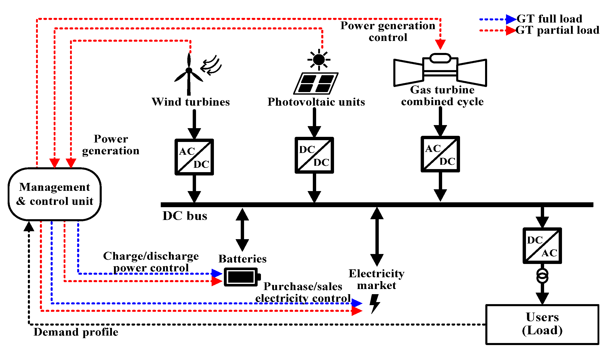
Figure 2 shows a conceptual diagram of the DG system. The figure is a simplified diagram of the target DG system but includes all the essential components. The detail of each component is described in Section 2.2, Section 2.3 and Section 2.4. Black solid arrows indicate the flow of electricity. Electricity from the power sources is converted to DC power through inverters. DC power is charged/discharged in batteries or traded in the electricity market according to the supply and demand of electricity. Users are supplied as much AC power as needed through the DC-to-AC inverter. In this study, the efficiency of the DC/AC inverter is assumed to be 92%.
Dotted arrows indicate the power control to match the generated electricity to the demand. The black dotted line means the user’s ever-changing demand. The management and control unit receives the demand information and controls the power generation of each power source. The blue dotted lines are for when the GT operates under full load, and the red ones are for when the GT operates under partial load. When the GT operates at full load, the charge/discharge power of the batteries and the purchase/sales electricity are controlled to fulfill the demand. When the GT operates at partial load, the management and control unit receive the information on the power generation of the RE as well as the demand information, and control the power generation of the GT as well as the charge/discharge power of the batteries and the purchase/sales electricity. The detailed power flow process is described in Section 3.3.
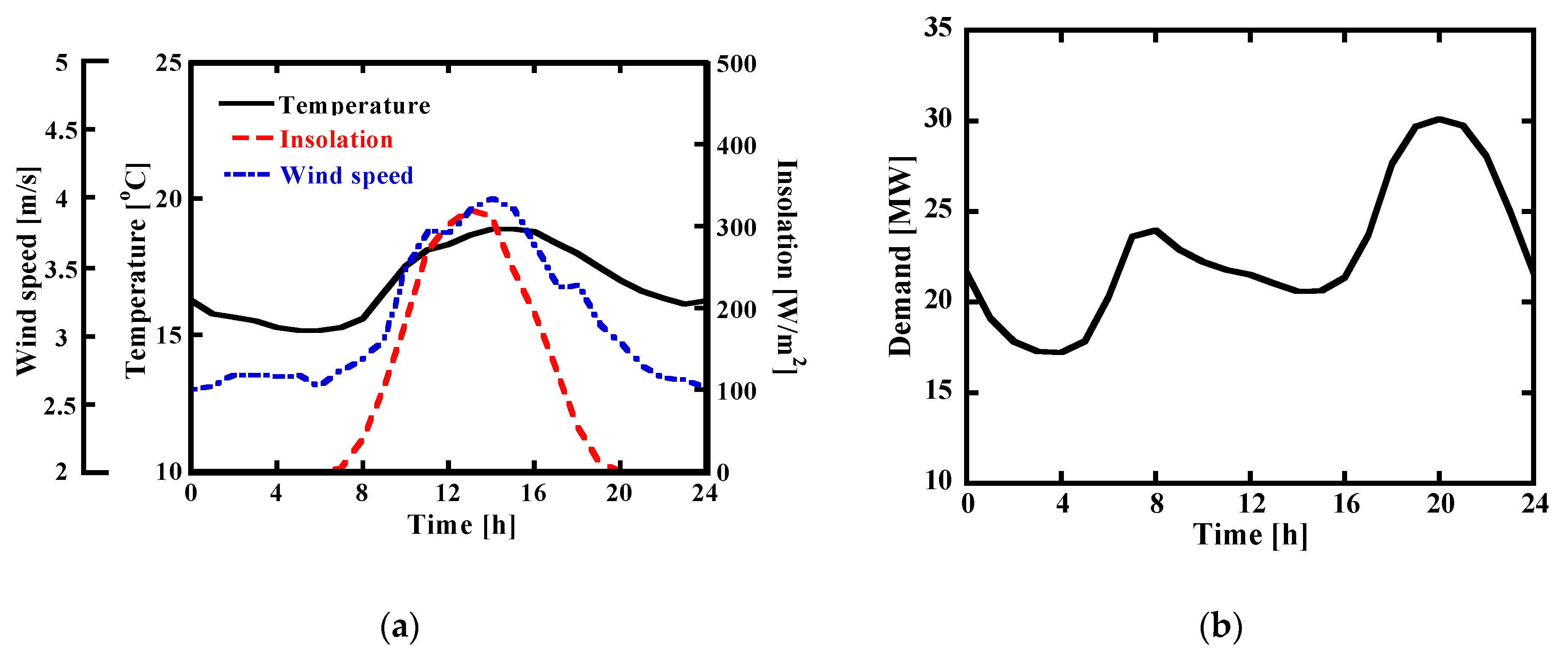
A district of Jeju City on Jeju Island, South Korea, was selected as the power-demand source in this study. The population of the district is 14% of the city population, and the electricity demand is about 20 MW. The average annual weather conditions of Jeju City were used [29].
The annual average demand profile was obtained by multiplying the power consumption factor [30] and the average regional power consumption [31]. The most recent available data from 2018 were used. Hourly calculation was adopted (the weather conditions and power demand change every hour). Figure 3 shows the annual weather conditions and power demand profile.
To analyze the DG system performance, in-house code was developed using MATLAB [32]. Each power source was modeled using physics-based governing equations. Polynomial equations from NASA [33] were used to calculate the properties of the air and combustion gas while assuming ideal gas behaviors. CoolProp [34] was used for the property calculation of water.

2.2. Gas Turbine Combined Cycle

Two GTs with different capacities were used to evaluate the effects of their performance changes on the sizing and operation strategy of the DG system under the same power demand. To simulate the GTCC, we used the specifications of 15-MW (Titan 130, Solar Turbines, San Diego, CA, USA) and 5.7-MW (Taurus 60, Solar Turbines, San Diego, CA, USA) GTs [35,36,37,38]. The components and power generation capacity of the GTCC using the 15-MW GT were obtained from actual operation [39]. The same values were used for the bottoming cycle (BC) parameters of GTCCs with the 15-MW GT and 5.7-MW GT. The GTCC simulation program is based on one developed by our research group [40]. The program was originally developed for steady-state [40,41] and dynamic GT simulations [42] and was further customized for the purpose of this study.

2.2.1. Gas Turbine

Figure 4 shows the configuration of the GT. In this study, we simplified the compressor and turbine as a single stage each, and all the cooling air was assumed to be extracted from the compressor outlet. The feasibility of this method has been verified [43], and it has been successfully used for performance analysis [44,45,46].
The design performance was analyzed by referring to datasheets [35,36] and published papers [37,38]. The design parameters are presented in Table 1. The GT power and efficiency are defined in Equation (1).
W ˙ G T = W ˙ S η c o n v , η G T = W ˙ G T / ( m ˙ f L H V )   where   W ˙ S = W ˙ t u r b η m e W ˙ c o m p
Natural gas (NG) is the fuel for the GT, and its low heating value (LHV) is 49,299 kJ/kg. Its composition is as follows: 91.33% methane, 5.36% ethane, 2.14% propane, 0.95% n-butane, and 0.22% nitrogen by volume. The mechanical efficiency was assumed to be 99%.
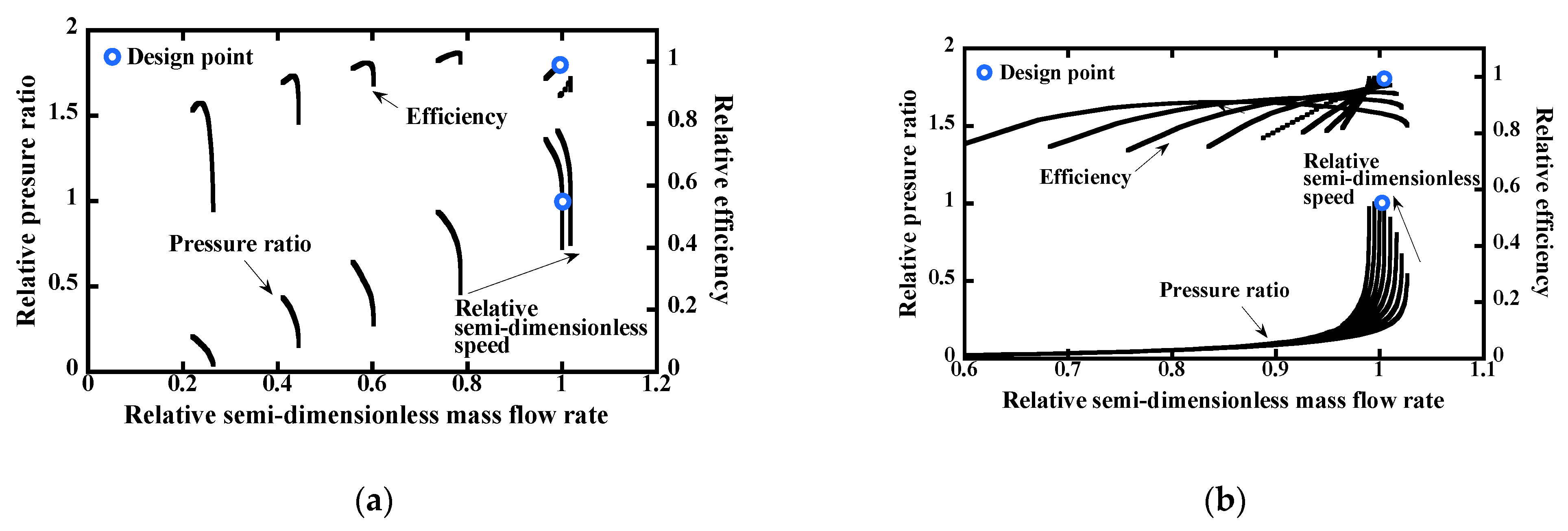
An off-design model is required to simulate the performance of the GT accurately. As shown in Figure 5, performance maps [47] were used to model the off-design behaviors. Each map consists of the semi-dimensionless flow rate, pressure ratio, isentropic efficiency, and the semi-dimensionless speed defined in Equation (2).
M = m ˙ i n T i n p i n ,   P R c o m p = p o u t p i n ,   P R t u r b = p i n p o u t Ω = N T i n , η c o m p = h o u t , s     h i n h o u t     h i n , η t u r b = h i n     h o u t h i n     h o u t , s
The powers were calculated as follows.
W ˙ c o m p = m ˙ a i r , i n ( h o u t h i n ) ,     W ˙ t u r b = m ˙ r o t o r , i n ( h r o t o r , i n h r o t o r , o u t )
A variable inlet guide vane (VIGV) in front of the compressor controls the inlet air flow rate during partial load operation. Compressor map scaling was used to predict the changes in the flow rate and pressure ratio according to the angle of the VIGV. The flow rate and pressure ratio were multiplied by the VIGV correction factor, as shown in Equation (4) [48].
m ˙ c o = m ˙ o r × c f V I G V ,     P R c o = P R o r × c f V I G V

2.2.2. Bottoming Cycle

The BC is a single pressure system and is composed of an economizer (ECON), evaporator (EVAP), superheater (SPHT), condenser, and pump. Figure 6 shows the configuration of the BC, and the design parameters are listed in Table 2. The design parameters were taken from the literature [40] using the same type of 15-MW GT, and the parameters were also equally applied to GTCC using the 5.7-MW GT. The power output of the steam turbine is calculated using Equation (5). The mechanical efficiency, gearbox efficiency, and generator efficiency were assumed to be 99%, 98.5%, and 98%, respectively.
W ˙ S T = m ˙ ( h i n h o u t ) η m e η g e a r η g e n
According to the calculation results, the power output of the steam turbine was 2.6 MW, and the exhaust gas temperature from the HRSG was 170.3 °C when the 15-MW GT was used. When the 5.7-MW GT was used, the power of the steam turbine was 1.2 MW, and the exhaust gas temperature was 167.8 °C. The simulated performance outputs are summarized in Table 2. In the off-design model, the operating pressure of the condenser is constant. The power consumption of the pump is very small compared to other components, so it was assumed that there is no change in the pump efficiency.
The NTU method was used to simulate the off-design models of the heat exchangers of the HRSG. The effectiveness of a heat exchanger was calculated using Equations (6)–(8). Equation (7) was applied to the ECON and SPHT, while Equation (8) was used for the EVAP.
N T U = U A C h e a t , min
ε = 1 exp [ N T U ( 1 + C r ) ] 1 + C r   where   C r = C h e a t , min C h e a t , max
ε = 1 exp ( N T U )
The overall heat transfer coefficient was calculated using Equation (9). The exponent is 0.6 according to the literature [49]. Finally, the unknown temperatures of the heat exchangers were calculated using Equation (10).
( U U d ) = ( m ˙ h o t m ˙ h o t , d ) a
{ ε = T c , o u t     T c , i n T h , i n     T c , i n ,       where   ( C h C c ) ε = T h , i n     T h , o u t T h , i n     T c , i n ,       where   ( C h < C c )
Equation (11) was used to describe the relationship between the pressure ratio and mass flow rate in the steam turbine. The inlet flow rate and outlet pressure of the steam turbine were determined by the off-design model of the HRSG and the operating pressure of the condenser. The control valve is fully opened and operates in sliding pressure mode. The sliding pressure operation provides better partial load efficiency for the GTCC in comparison to other operation modes [50].
m ˙ i n T i n p i n / m ˙ i n , d T i n , d p i n , d = 1 ( 1 P R ) 2 / 1 ( 1 P R d ) 2

2.3. Renewable Energy

2.3.1. Photovoltaics

A commercial 53-W PV module [51] was used to simulate the PV system. Table 3 shows the main parameters for the PV module in standard test conditions. The PV module is controlled by maximum power point tracking (MPPT) using the perturb and observe (P&O) algorithm.
The characteristics of the PV module are determined by arraying PV cells. The electric current of a PV cell was calculated using Equation (12). The exponent indicating the degree of ideality is 1.6 according to the literature [51,52]. The values of the serial and parallel resistances were calculated by performing iterative calculations at the maximum power point (MPP). The light generation current is dependent on the insolation and temperature, as described in Equation (13).
I P V = I p h I o [ exp ( V P V + R s I P V a V T ) 1 ] V P V + R s I P V R p
I p h = [ I S T C , s c + K i ( T T S T C ) ] × G G S T C
The saturation current was calculated using Equation (14). The reference temperature is 301.18 K, and the saturation current at the reference temperature is 2.07 × 10⁻⁶ according to the literature [51]. The band gap energy is 1.12 eV [53].
I 0 = I 0 , r e f [ T T r e f ] 3 exp [ q E g a k ( 1 T r e f 1 T ) ]
Finally, the power output was calculated as follows considering the number of installations and capacity factor.
W ˙ P V , n e t = n P V × I × V × η i n v = n P V × W ˙ P V ,       C F P V = W ˙ P V W ˙ P V , r
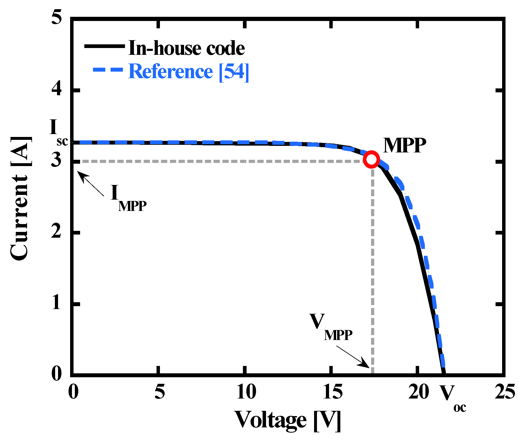
Figure 7 compares the characteristic I-V curves of the PV predicted by our model and data from the manufacturer [54], which show the reliability of the model.

2.3.2. Wind Turbine

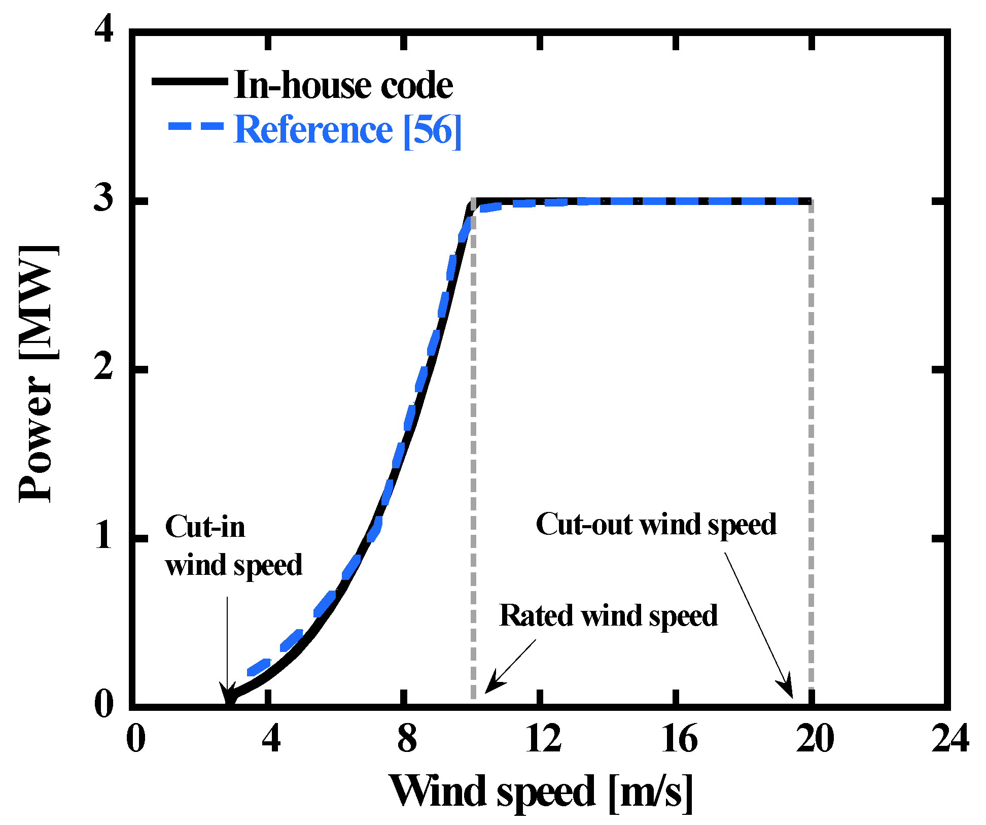
The wind speed at the hub height is calculated by the wind profile power law in Equation (16). The exponent is 0.14 according to the literature [55].
v 0 v = ( H H 0 ) α
A 3-MW off-shore WT was modeled in this study [56]. It was assumed that wind blows from the front of the WT. The main parameters are presented in Table 4. The power output is calculated as follows in consideration of the number of installations and capacity factor.
W ˙ W T , n e t = n W T × ( 1 2 ρ A v 3 C p ) × η i n v = n W T × W ˙ W T ,       C F W T = W ˙ W T W ˙ W T , r
The power coefficient is calculated using Equation (18), which is a function of the tip-speed ratio and blade pitch angle.
C p = 1 2 ( 116 λ i 0.4 β 5 ) exp 16.5 λ i λ i = ( 1 1 λ   +   0.089 0.035 β 3   +   1 )       where   λ = ω r v
The WT power is controlled according to the wind speed based on Equation (19). The WT does not generate electricity when the wind speed is below the cut-in speed or above the cut-out wind speed. When the wind speed is between the cut-in and rated wind speeds, the MPPT control adopting the P&O algorithm is used, and the blade pitch angle is fixed for optimal power generation. The optimal pitch angle was calculated as 2.3° using the given parameter data. When the wind speed is higher than rated wind speed, the blade pitch angle is controlled to sustain the rated power.
W ˙ W T ( U ) = { 0   ( U   <   U c i     or   U   >   U c o ) W ˙ W T   ( U c i   U U r   ) W ˙ r   ( U r < U U c o   )
Figure 8 shows the relation between the wind speed and the generated power from the WT. The results of the simulation model are compared with the data provided by the manufacturer [56]. The model results are quite close to the actual data from the manufacturer.

2.4. Battery Energy Storage System

Lead-acid batteries have been proven to be stable and reliable and are being used as utility-scale batteries [57]. Therefore, a lead-acid battery was also adopted in this study. The state of charge (SoC) is the percentage of the remaining capacity of the battery. Conversely, the depth of discharge (DoD) is the percentage of capacity removed from the fully charged battery. In general, full charging or discharging accelerates battery aging, so there are minimum and maximum values of SoC [58].
The parameters of the lead-acid battery are listed in Table 5. It was assumed that the charge/discharge of the battery is done according to constant-current/constant-voltage mode. The battery is charged or discharged with a constant current until the voltage reaches the final voltage (the cut-off voltage) [59,60]. When the voltage reaches the limit, it is charged or discharged with a constant voltage. The charging/discharging efficiency is 89.5% [61], and the charge/discharge cycle was assumed to be once a day.
To simulate the lead-acid battery, the CIEMAT model [62] was used. The battery capacity is expressed using the discharge current and temperature, as shown in Equation (20). We assume that the rated charge time of the battery is 10 h.
C C 10 = 1.67 1 + 0.67 ( I B a t I 10 ) 0.9 ( 1 + 0.005 Δ T )   where   Δ T = T 25
The voltage is calculated using Equation (21).
V c h , B a t = [ 2 + 0.16 ( 1 S o C ) ] + I B a t C 10 ( 6 1 + I B a t 0.86 + 0.48 ( 1 S o C ) 1.2 + 0.036 ) × ( 1 0.025 Δ T ) V d i s , B a t = [ 2.085 0.12 ( 1 S o C ) ] I B a t C 10 ( 4 1 + I B a t 1.3 + 0.27 S o C 1.5 + 0.02 ) × ( 1 0.007 Δ T )
The SoC and DoD are calculated using Equations (22) and (23). The amount of battery power is calculated with Equation (24).
S o C ( t ) = { S o C ( t 1 ) + η c h Q ( t ) C S o C ( t 1 ) Q ( t ) η d i s C   where   Q ( t ) = I × t
D o D ( t ) = 1 S o C ( t )
S ( t ) = η i n v Q ( t )
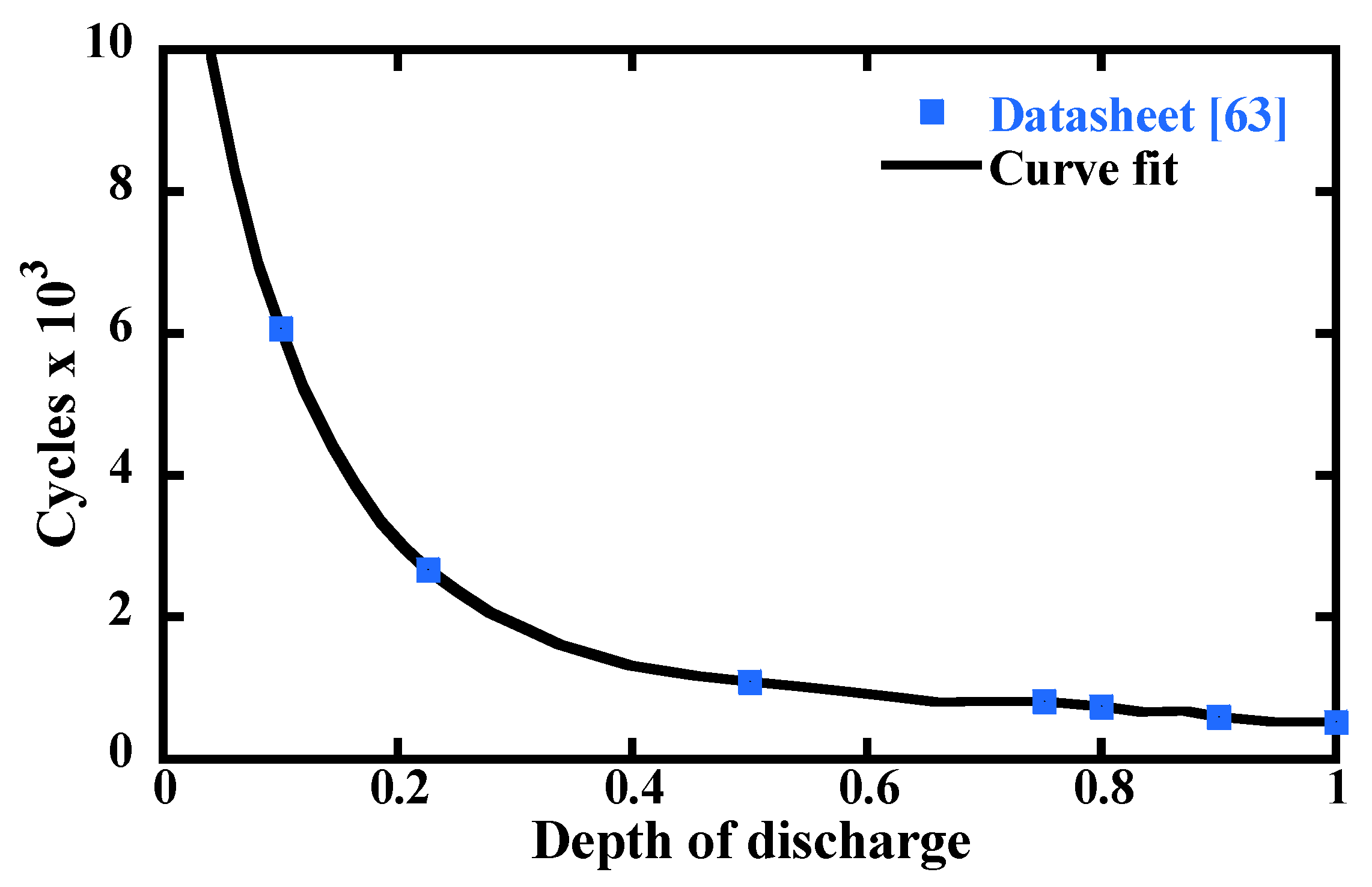
The lifetime of the battery is related to the number of charge/discharge cycles. Figure 9 [63] shows the cycles to failure versus DoD for a typical deep-cycle lead-acid battery. The numerical curve-fitting relation of Figure 9 is based on Equation (25).
C y c l e t o t = 12193 78268 × D o D + 205444 × D o D 2 234878 × D o D 3 + 96518 × D o D 4

3. Analysis and Optimization

3.1. Overview

Optimal sizing and operation strategies are essential for providing stable power supply in DG. To obtain the optimal sizing and operation strategy, it is necessary to analyze the performance of the DG system over time and to use an optimization algorithm. However, traditional numerical methods have limitations in performing complete optimization because they are based on a highly non-linear physical model to describe the detailed operating characteristics. This is also true if we try to perform the optimization directly using our in-house code, which analyzes the performance of the DG system through several physics-based governing equations and the Newton–Raphson method to solve them simultaneously. Therefore, the computational load would increase rapidly if optimization were attempted using the physics-based model directly.
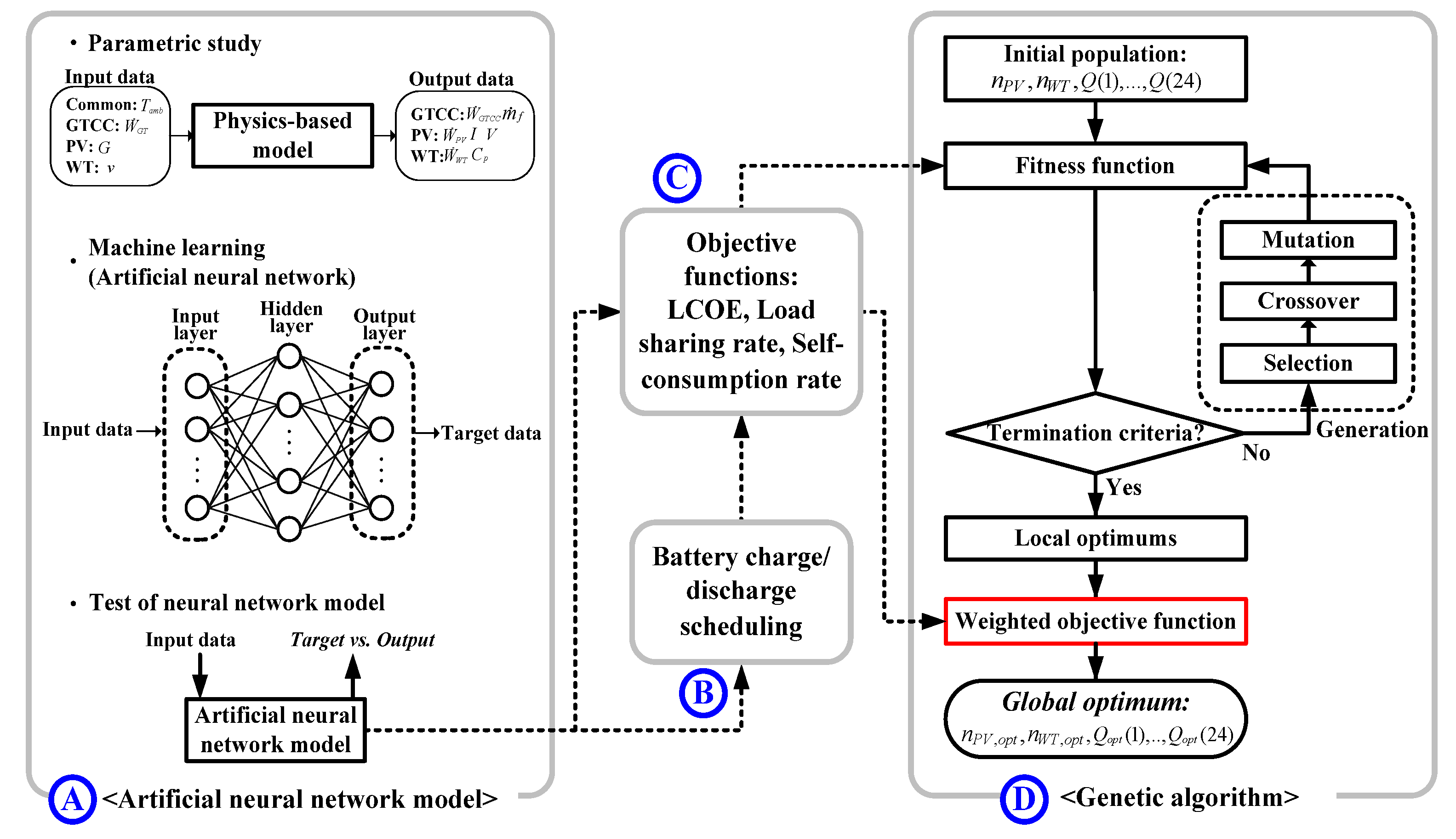
Therefore, we decided to perform the optimization using a stepwise method to reduce the calculation burden drastically and to perform the optimization effectively. Firstly, an ANN was adopted to obtain a vast amount of operation data based on the limited results from running the physics-based model. Next, the battery charge/discharge scheduling was determined using the ANN model. Objective functions for optimization were then constructed based on operating data, including the results of the battery scheduling. Finally, the optimization was conducted using a GA.
The overall processes for optimization of the sizing and operation strategy of the DG system are shown in Figure 10. The optimization processes can be divided into processes A–D. An optimal method was found for the three cases to obtain the best sizing and operation strategy of the DG system. In case 1, a 15-MW GT is used, and it operates under full load regardless of the operation characteristics of the RE. In case 2, the 15-MW GT is still used, but it is operated under partial load according to the operation characteristics of the RE.
The actual lowest power output of a GT is usually limited by emissions regulations. The ratio of the lowest power to the full power is usually called the turn-down ratio. In this study, the turn-down ratio was set as 50% of the rated power by referring to current practices [64]. In case 3, a 5.7-MW GT is used, and it operates under full load all day. In this case, the GT alone cannot satisfy the electricity demand, so it is necessary to use a significant amount of the RE power to satisfy the demand.
  • Case 1: 15-MW GT, full load operation
  • Case 2: 15-MW GT, partial load operation (down to 50% power)
  • Case 3: 5.7-MW GT, full load operation

3.2. Artificial Neural Network Model

Feed forward neural networks (FFNs) are the most widely used neural networks. An FFN has input layers, output layers, and hidden layers. The number of neurons in the hidden layer affects the accuracy of the ANN model and is determined by the size of the input and output layers. This value is uncertain, so it is determined empirically. In this study, the ANN model for the GTCC and RE was constructed using the Deep Learning Toolbox of MATLAB [32]. The construction process of the ANN model is shown in process A in Figure 10.
Before constructing the model, a parametric study was first performed using a physics-based model to obtain a database for learning. The database is summarized in Table 6. The input data were divided into 30 sections to use the appropriate dataset for analysis. The training function was the Levenberg–Marquardt training function, which is the fastest, and the ANN model had 2000 epochs. The number of hidden neurons with the smallest mean squared error (MSE) was selected.
In the case of a conventional ANN model trained using measured data, a test dataset is necessary to avoid overfitting. However, in this study, the test dataset is unnecessary because the ANN model is trained with data of a uniform distribution obtained from the physics-based model. Therefore, a larger amount of dataset can be used to train the model, making it possible to build an ANN model that is more similar to a physics-based model. Accordingly, 90% of the dataset was used for training and the remaining 10% was used for validation. The ANN model was constructed using the database through the physics-based model and hyper-parameters.

3.3. Battery Charge/Discharge Scheduling

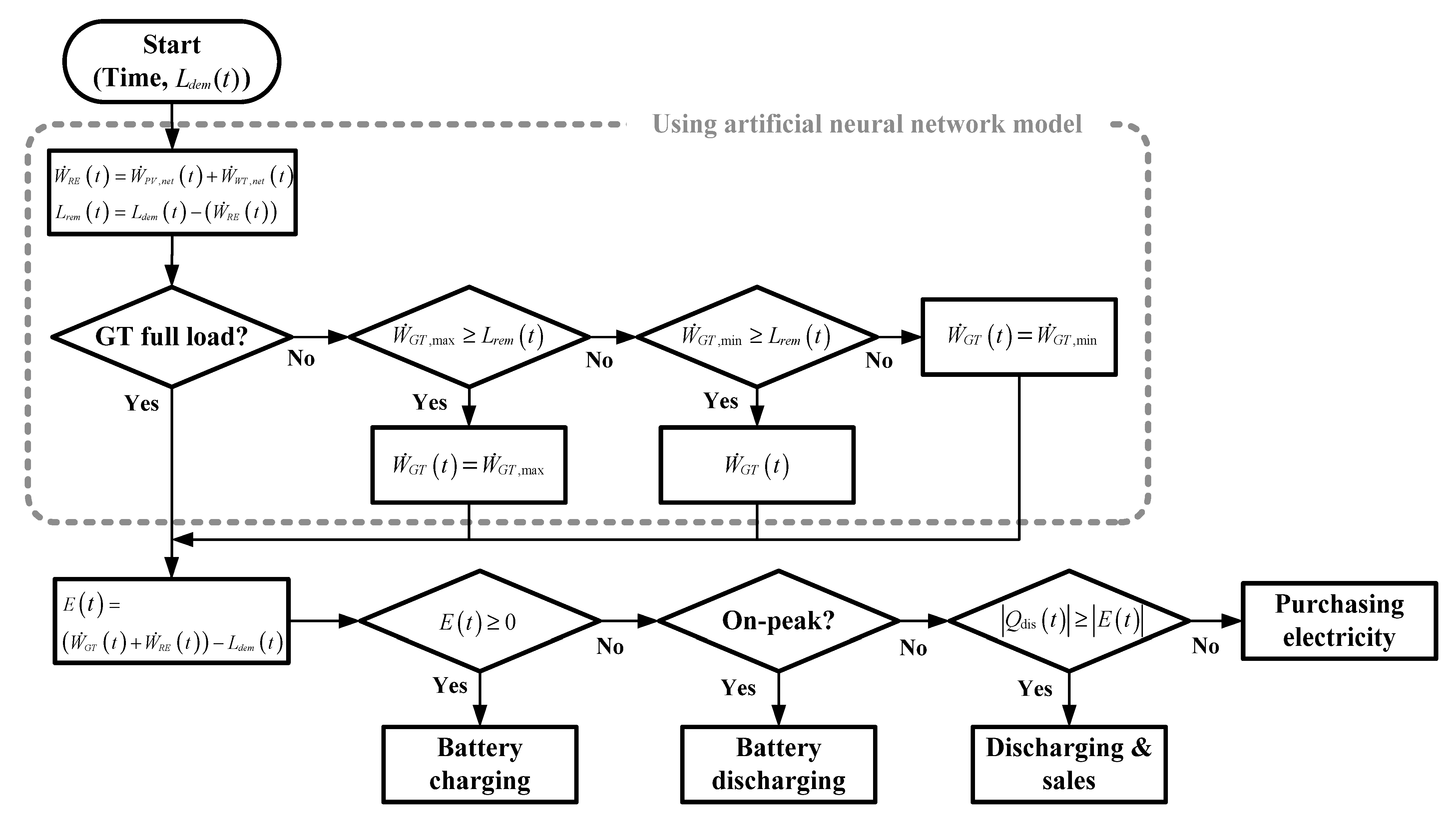
The battery charge/discharge scheduling was used to calculate the objective function of the GA (see process B in Figure 10). Figure 11 shows the detailed process for the scheduling. The power outputs of the RE and GTCC were calculated using the ANN model. The power outputs of the RE were calculated according to ambient air conditions. Then, the surplus or insufficient electricity for users was determined according to the operation mode of the GT.
If the GT is operated at full load, the power of the GT is generated fully regardless of the demand. If not, the GT operates between maximum and minimum to match the demand. When the electricity generated from the power sources satisfies the power demand and some remains, all the remaining electricity charges the batteries. When the generated electricity is not sufficient to meet the demand, a decision is made about whether to discharge the electricity from the batteries or to purchase electricity from the electricity grid. The factors considered in this decision are the amount of electricity charged in the batteries and the electricity price according to time.
The electricity is first discharged during the on-peak time, and then the remaining electricity in the batteries is discharged at mid- and off-peak times. If electricity is insufficient to meet the demand, electricity is purchased from the grid to compensate for the shortfall. Otherwise, the electricity left in the batteries is sold to the electricity grid. The battery scheduling for one day is determined through this process, and the battery lifetime is calculated by Equation (25).

3.4. Objective Functions for Optimization

The objective functions for the optimization were (1) the levelized cost of electricity (LCOE), (2) the load sharing rate of the RE, and (3) the self-consumption rate. They were embedded in the optimization process in the fitness function of the GA (see process C in Figure 10). The objective functions were calculated using the output of the power source and the result of the battery scheduling.
LCOE is used as an index representing the cost-effectiveness and sizing of the various power generation systems, especially with RE. The lower the LCOE, the higher the cost-effectiveness is [65]. LCOE is calculated using Equation (26) by considering the total generation cost including installation cost, O&M cost, fuel cost, electricity purchase cost, sales rate, and the degradation rate of each generator during the project period. The usual PV lifetime is known to be 25 years [66], which was selected as the project period for the DG system.
O b j 1 = L C O E = C a p + n = 1 T ( C a p × i + O M + F C + ( P u r e l S a l e s e l ) ) ( 1 + r ) n n = 1 T ( E G T C C × ( 1 d G T C C ) + E P V × ( 1 d P V ) + E W T × ( 1 d W T ) ) ( 1 + r ) n
The parameters and data used in the LCOE calculation are summarized in Table 7. The cost of the GTCC was calculated using a correlating equation for the price of commercial GTCC plants [50,67]. The costs of the PV module, WT turbine, and battery were obtained from references in consideration of their cost trends [68,69]. With PV and WT, the BoS cost is half the cost of the PV module or WT turbine [70,71]. Fuel cost was obtained from the local NG price [72], and the average exchange rate in 2020 (1180 won/$) was applied [73]. The yearly amount of generated electricity was calculated by considering the degradation rate and discount rate [69].
The electricity purchase cost was calculated by considering the average annual ambient temperature and the electricity prices in spring and autumn in South Korea, as summarized in Table 8 [74]. All electricity sales were assumed to be from the RE. In South Korea, the renewable portfolio standard (RPS) is being enforced to promote the expansion of RE. According to the RPS, the sales of electricity are determined by the sum of the system marginal price (SMP) and renewable energy certificate (REC) price while considering weights.
Weights of 0.7 for PV and 2.0 for WT were used in accordance with the regulations in South Korea. The SMP and REC price vary depending on the time and market conditions of the day before. The hourly SMP shown in Figure 12 was used, and the REC prices were 102,472 won/MWh for PV and 102,868 won/MWh for WTs [75].
The load sharing rate of the RE was obtained using Equation (27). The load sharing rate is the ratio of the generated electricity to the power demand. It was assumed that the electricity demand and the amount of generated electricity from RE changes every hour, so the load sharing rate was calculated as the average value of the load sharing rate for 1 day.
O b j 2 = Load   sharing   rate = W ˙ P V , n e t ( t ) + W ˙ W T , n e t ( t ) L ( t )
The self-consumption rate is defined as the percentage of electricity that is consumed locally from the overall generated electricity. The expression for the self-consumption rate is Equation (28) [76]. A high self-consumption rate means that the power generation is not excessive compared to demand, while a low self-consumption rate means that the power sources are somewhat excessive compared to demand.
O b j 3 = Self - consumption   rate = t = 1 24 M i n ( L ( t ) , W ˙ n e t ( t ) + S ( t ) ) t = 1 24 W ˙ n e t ( t ) where   W ˙ n e t ( t ) = W ˙ P V , n e t ( t ) + W ˙ W T , n e t ( t ) + W ˙ G T C C ( t )

3.5. Genetic Algorithm

A GA was used in the final step of the entire process, as shown in Figure 10. The Optimization Toolbox provided by MATLAB [32] was used. As a result, the entire calculation package covering all the steps in Figure 10 was constructed in a MATLAB framework.
The procedure of finding the optimal solution using a GA is shown in process D in Figure 10. A fitness function is used to determine the fitness of the initial population, and generations made using selection, crossover, and mutation are repeated until the population satisfies the termination criteria. After several generations, local optimums that satisfy the termination criteria are produced. The initial population of the GA was set at 1000, and the number of generations was set as at least 100. To find the solution to the optimization problem with multi-objective functions introduced in Section 3.4, a computational option called ‘gamultiobj’ was used.
The standard GA provided by MATLAB outputs many local optimums. Therefore, a ranking operation is required to obtain only one global optimum. In this study, a weighted objective function was used to find one global optimum among the local optimums. The weighted objective function consists of a combination of the objective functions described in Section 3.4. For stable and profitable DG, this study focused on the cost-effectiveness of the DG system and the ratio of the power generated from RE. In other words, we assumed that the sizing and operation strategy is optimized when the LCOE is the lowest, and the load sharing and self-consumption rate are the highest. As a result, the weighted objective function was set using the following equation, where the three weights for the individual objective functions were set to be equal.
Weighted   objective   function = 1 3 O b j 1 , max O b j 1 O b j 1 , max O b j 1 , min + 1 3 O b j 2 O b j 2 , min O b j 2 , max O b j 2 , min + 1 3 O b j 3 O b j 3 , min O b j 3 , max O b j 3 , min
It is assumed that the PV modules and batteries are arrayed in series. The capacity of the battery was calculated as the sum of all remaining power after meeting the demand in consideration of the constraints of the SoC. The sizing and operation strategy was optimized using 26 design variables, such as the numbers of PV units and WTs and the hourly charged/discharged energy of the battery. The optimization problem in this study is summarized in Equation (30). At least one PV unit and WT must be installed, and the charged and discharged energy of the battery is determined in consideration of the electricity generation and electricity transaction volume.
  • Maximize the weighted objective function (Equation (31)) subject to
    n P V > 0 ,   n W T > 0 ( n   is   integer ) Q ( t ) = E ( t ) ,   where   E ( t ) 0 Q ( t ) = E ( t ) + X ( t ) ,   where   E ( t ) < 0 ( t = 1 , 2 , , 24 )
  • Design variables: n P V ,   n W T , Q ( 1 ) ,   Q ( 2 ) , ,   Q ( 24 )

4. Results and Discussion

4.1. Performance of the ANN Model

A personal computer with a quad-core processor (Intel Core i7-4770 3.40 GHz) and 16 GB of RAM was used in the simulation. Prior to the main analysis, the ANN model’s accuracy and computational efficiency were checked. In building the ANN model, it took 511.9 s (GTCC: 478.5 s, PV: 31.44 s, WT: 1.995 s) to collect data from the physics-based model and 184.2 s (GTCC: 55.99 s, PV: 48.06 s, WT: 80.17 s) to train the ANN model.
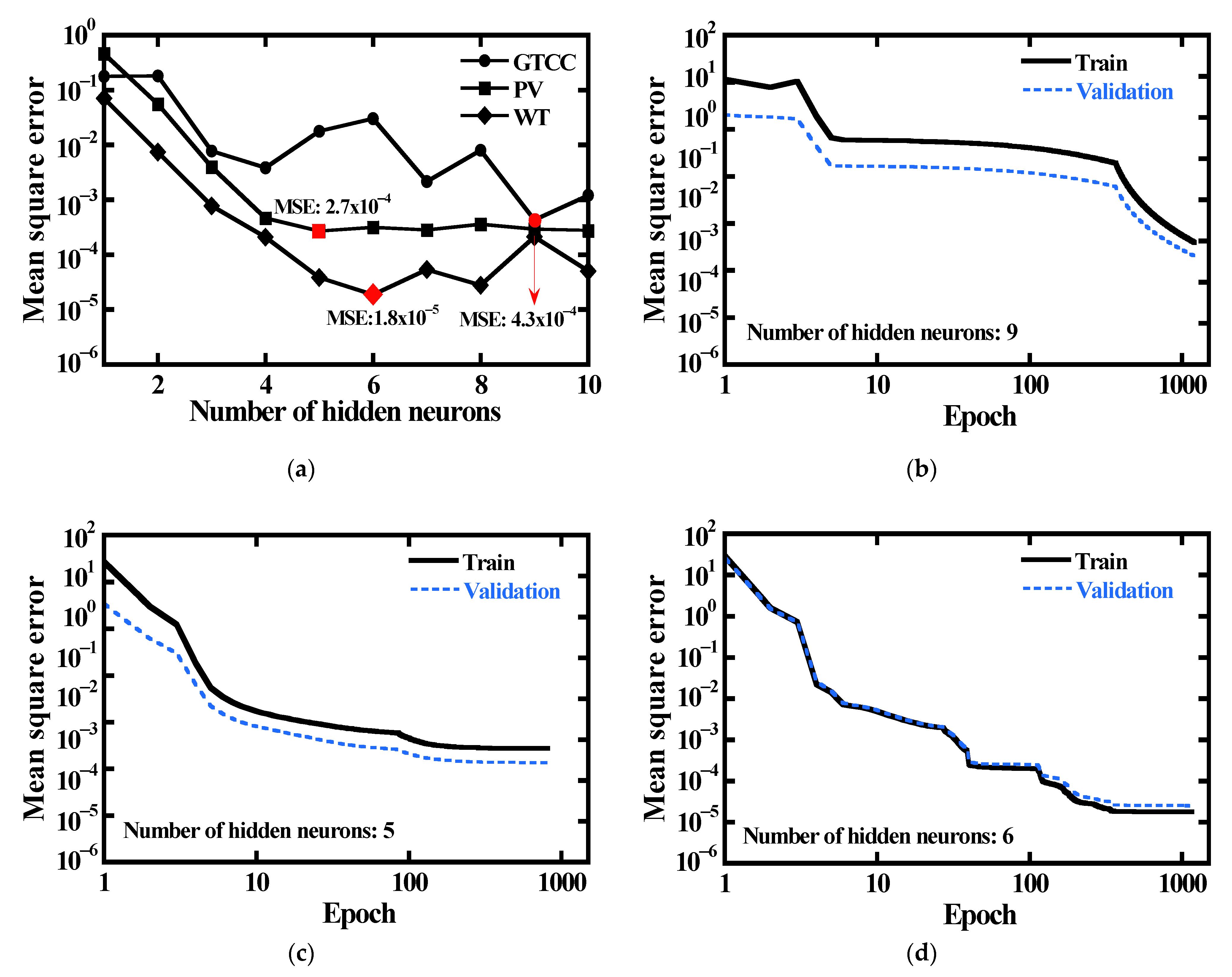
Figure 13 shows the training results of the ANN model. Figure 13a shows the MSE of the ANN model according to the number of hidden neurons. The ANN model was trained and validated according to the epoch by selecting the number of hidden neurons with the smallest MSE in Figure 13a. The training and validation results of each ANN model were illustrated in Figure 13b–d. The ANN model of the GTCC had nine hidden neurons, and MSE was 4.3 × 10⁻⁴. In the ANN model of the PV module and WT, seven and six hidden neurons were selected, and the MSE values were 2.7 × 10⁻⁴ and 1.8 × 10⁻⁵, respectively.
The input datasets in Table 6 were used to check the performance of the ANN model, and their ranges were segmented randomly by 100. The input data were put into the physics-based model and the ANN model to compare the power output. The performance results are summarized in Figure 14. The results confirmed that the ANN model was well built.
Table 9 shows the results of the computational efficiency improvement through the ANN model. In the table, “Simple” denotes conditions where the performance of the DG system was analyzed using one randomly combined optimization parameter set, while “Total” means conditions where the optimization was conducted using the GA. When analyzing the performance in the “Simple” conditions, the calculation time was a minimum of 28.06 s and maximum of 58.07 s when using the physics-based model. The time was drastically reduced when using the ANN model to a minimum of 0.004716 s and a maximum of 0.002860 s.
In the “Total” conditions, the GA performed a total of 100,000 variations (initial population × generations) for the performance analysis. Considering the variations, the calculation time of the physics-based model was estimated to be a minimum of 2,806,000 s and a maximum of 5,807,000 s (32–67 days). However, the calculation time of the ANN model was a minimum of 259.8 s and a maximum of 538.7 s (4–9 min).
Comparing the memory required for calculation, a maximum of 426 MB and a minimum of 387.8 MB were required for the calculation using a physics-based model, but a maximum of 175.9 MB and a minimum of 160.2 MB were required for the calculation using the ANN model.
In summary, the computation speed of the ANN model is a minimum of 5200 times faster than the physics-based model and a maximum of 22,300 times faster. Even when including the data collection and training time, the time required was reduced by at least 2200 times and up to 6000 times. Even when the ANN model was used, the memory required for the calculation was reduced by up to 62.3% compared to when the physics-based model was used. Consequently, the calculation burden of the DG system performance required for optimizing the size and operation strategy can be greatly reduced. Thus, the validated ANN model was used to generate the performance of the DG system in a vast range of operating conditions, as shown in Section 3.2 and process D of Figure 10.

4.2. Optimization Results

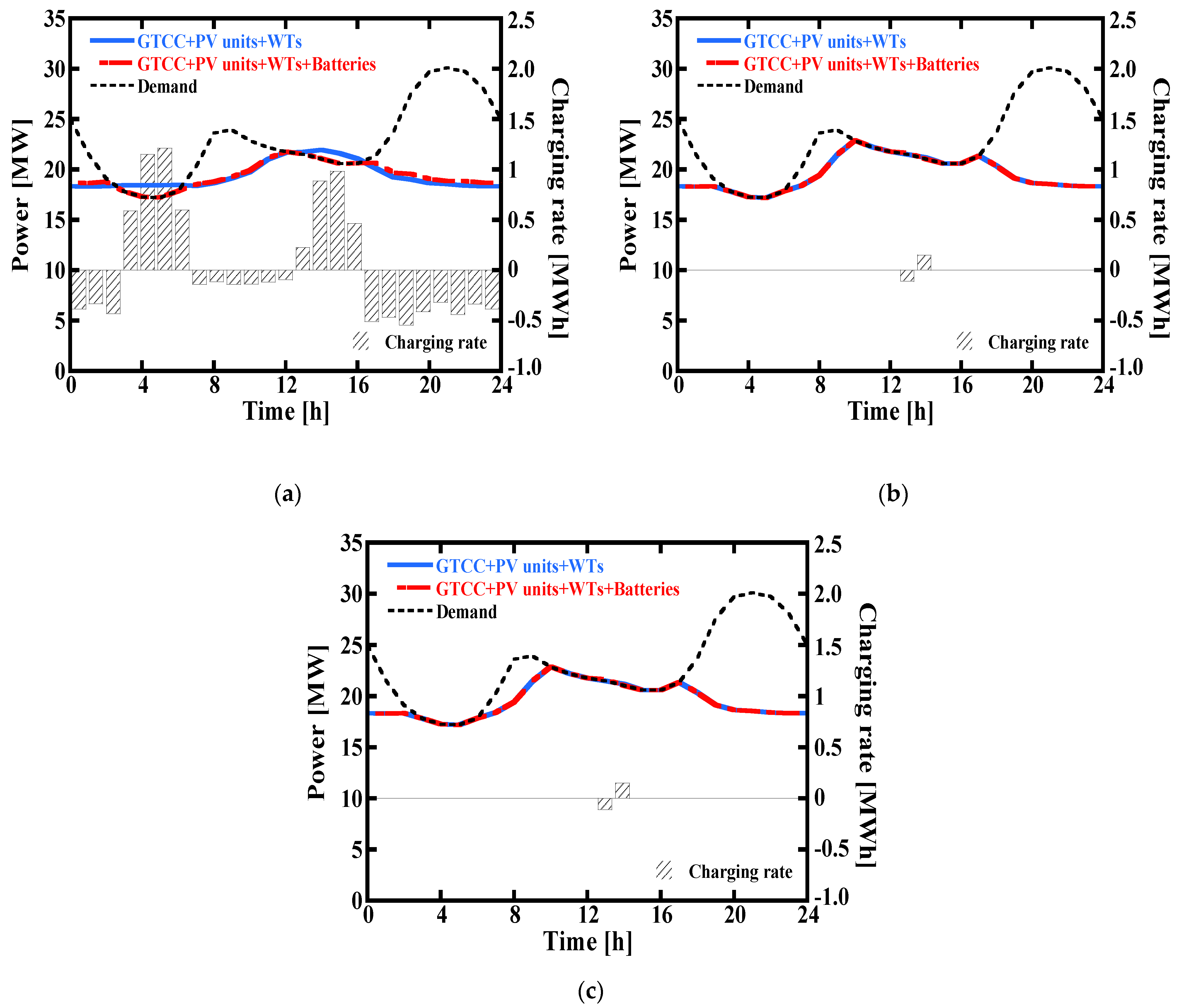
The results of the optimization for each case are shown in Table 10 and Figure 15. The details of the variations in design variables and objective functions according to the number of calculations for the representative case (case 1) are presented in Appendix A. In Figure 15, the black dotted line indicates the power demand from Figure 3. The solid blue line shows the sum of the produced power excluding the batteries, and the red chain line represents the total amount of power generated, including the battery discharge power. The bar graph is the charged/discharged energy of the batteries. A positive value means charged energy, and a negative value means discharged energy.
In case 1, the 15-MW GT operates under full load all the time. To meet the electricity demand, 138,117 PV units (7.6 MW) and 2 WTs (6 MW) must be installed. However, during the daytime, the average capacity factor of the PV was 8.6%, and the capacity factor of the WT was 21.4%, so the power generated from RE was about 0.5 MW for the PV units and 1.3 MW for the WTs on average. The load-sharing rate based on the output of the RE was 8.0%.
The battery capacity in case 1 was 7.6 MWh because only the battery was used as a flexible resource. The DoD and cycles of the batteries were 57.9% and 1005.9 cycles. Due to the large capacity of the batteries, LCOE was relatively high at 0.1947 $/kWh. The batteries were charged with 6.1 MWh of electricity for 8 h, and 4.9 MWh of electricity was discharged for 16 h when the power demand was insufficient.
In case 2, the 15-MW GT ran at partial load. In this case, since the GT and battery were flexible resources, the required number of PV units was 613,062 (32.5 MW), and the required number of WTs was 2 (6 MW). The average power generation of the PV and WT was about 2.8 MW and 1.3 MW, respectively.
Unlike case 1, the amount of power generated from the GT was adjusted to match the power demand at 3:00–6:00 and 13:00–16:00 when the power demand was low. In particular, since the turn-down ratio of the GT was set to 50% of its rated power, the RE capacity could be increased, while the capacity of the batteries could be kept low. The load-sharing rate of the RE was 17.2%, which was about 9.2%p higher than that of case 1. The capacity of the batteries was 0.2 MWh, which is much smaller than in case 1 (i.e., only 2.7% that of case 1), because the batteries were charged at 14:00 when the RE power peaked.
Considering the SoC constraints, the actual power stored in the batteries was 0.15 MWh, and 0.11 MWh was discharged. Only 0.02 MWh was used to meet the demand for the other peak time, when the purchase price of electricity was high, and the rest of the electricity was sold through the electricity grid. Due to the short charge and discharge time, a large amount of power was transferred from the batteries at one time, so the batteries had 795.8 charging/discharging cycles, which were 20.9% shorter than in case 1.
In case 2, the RE capacity was larger, and the battery charge/discharge cycles were shorter than in case 1, so battery replacement must be performed more often (i.e., the life is shorter). However, the cost reduction effect due to the sensible reduction in battery capacity was greater than the negative effect of the more frequent battery replacement, so LCOE was 0.1667 $/kWh, which is 14.4% lower than in case 1.
Case 3 used a 5.7-MW GT, which has much lower power capacity compared to cases 1 and 2, and it runs at full load. The number of PV units was 693,810 (34 MW), and the number of WTs was 6 (9 MW). The power generation was 3.2 MW for the PV and 1.9 MW for the WTs. The load-sharing rate of the RE was 21.5%, which was 13.5%p higher than in case 1 and 4.3%p higher than in case 2.
In this study, it was more economical to meet the demand by purchasing electricity from the electricity grid than to increase the capacity of the batteries. As a result of the optimization, the capacity of the batteries was 0.6 MWh, which was larger than in case 2 due to the increased RE, and the batteries were charged at 14:00 when the amount of power generated from the RE peaked. Considering the constraints of the SoC and charging/discharging efficiency, the charged energy was 0.5 MWh, and the discharge was 0.36 MWh.
An amount of 0.26 MWh of the total discharged energy was sold to the market, and the rest was discharged to supply the demand at times when the electricity purchase price was high. As with case 2, since the batteries in case 3 charge or discharge a large amount of electricity at once, the DoD was high at 66.7%, and the charge/discharge cycle was 795.0. In case 3, the battery capacity was minimized, but due to the increased capacity of RE and the cost of purchasing electricity to meet the power demand, LCOE was 0.2891 $/kWh, which is 48.5% higher than in case 1 and 73.4% higher than in case 2.

5. Conclusions

The results and conclusions of this study are summarized as follows.
  • To simplify the calculation process of the complex DG system, an ANN model was constructed. The current ANN model based on the physics-based model, unlike the conventional ANN model based on measured data, did not require a test dataset for overfitting. Therefore, a large proportion of the dataset was used for training the ANN model, so the ANN model mimicked the physics-based model very well: The MSE had a maximum of 2.7 × 10⁻⁴ and a minimum of 1.8 × 10⁻⁵. As a result, the ANN model showed an improvement of at least 5200 times and at most 22,300 times for calculation time and reduced the memory required for calculation by up to 62.3%. Therefore, the ANN model is suitable for use in the optimization calculation of the DG system.
  • The sizing and operation strategy of the DG system was optimized using the GA. In addition, to determine only one global optimum solution among many local solutions from GA, a weighted objective function considering eco-friendliness and cost-effectiveness was used. The optimization results were summarized for three cases according to the operation mode of the GT. In case 1, only the batteries acted as flexible resources. Hence, it had the smallest sharing rate of RE and the largest battery capacity, but had the longest life of the battery. In case 2, not only the batteries but also the GT were used as flexible resources, so the capacity of the batteries was the smallest. In case 3, the capacity of the GT is lower compared to cases 1 and 2, and it had to operate at full load. It was found to be more economical to purchase the electricity from a grid than to install the large capacity batteries, so case 3 had the smaller battery capacity than case 1. However, in case 3, the installed capacity of RE was larger, which makes the battery capacity larger than that of case 2. In cases 2 and 3, the life of the battery was shorter due to rapid charging and discharging.
  • Excessive power generation compared to demand leads to an increase in required battery capacity, resulting in an increase in LCOE. In case 2, where the GT operated flexibly, the LCOE was 14.4% lower than case 1 and 42.3% lower than case 3. In other words, minimizing the role of the battery through flexible operation of a conventional generator like the GTCC is the best choice for feasible and economic performance in isolated regional DG.
This study is significant in that the artificial intelligence scheme that combines the ANN and GA was applied to optimize the distributed generation system in terms of cost-effectiveness and eco-friendliness, while improving the computational efficiency drastically. The method is expected to be utilized effectively for the accurate optimization of complex energy networks such as DG clusters, as well.

Author Contributions

Conceptualization, H.-R.K. and T.-S.K.; methodology, H.-R.K.; software, H.-R.K.; formal analysis, H.-R.K.; investigation, H.-R.K.; resources, T.-S.K.; data curation, H.-R.K.; writing—original draft, H.-R.K.; writing—review and editing, H.-R.K. and T.-S.K.; supervision, T.-S.K.; project administration, T.-S.K.; and funding acquisition, T.-S.K. All authors have read and agreed to the published version of the manuscript.

Funding

This research was funded by the National Research Foundation of Korea (NRF) grant funded by the Korean government (MSIT) (No. 2020R1A2B5B01002460).

Institutional Review Board Statement

Not applicable.

Informed Consent Statement

Not applicable.

Conflicts of Interest

The authors declare no conflict of interest.

Nomenclature

AArea (m2)
ANNArtificial neural network
aIdeality factor (-)
BCBottoming cycle
CCapacity (Ah)
CheatHeat capacity (kJ/K)
CpPower coefficient (-)
CrHeat capacity ratio (-)
CFCapacity factor (-)
CapCapital cost ($)
CycleCycles of battery (-)
cfCorrection factor (-)
DGDistributed generation
DoDDepth of discharge (-)
dDegradation rate (-)
EElectricity generation (MW)
ECONEconomizer
ESSEnergy storage system
EVAPEvaporator
EgBand gap energy (eV)
FFNFeed forward neural network
FCFuel cost ($)
GSolar Irradiation (W/m2)
GAGenetic algorithms
GTGas turbine
GTCCGas turbine combined cycle
ICurrent (A)
iDiscount rate (-)
HHeight (m)
hSpecific enthalpy (kJ/kg)
Kshort-circuit current temperature coefficient (A/K)
kBoltzman constant (1.38 × 10⁻²³ J/K)
LPower demand (MW)
LCOELevelized cost of electricity ($/kWh)
LHVLower heating value (kJ/kg)
MSemi-dimensionless mass flow rate (ms K0.5)
MPPMaximum power point
MPPTMaximum power point tracking
MSEMean squared error
m ˙ Mass flow rate (kg/s)
NSpeed (rpm)
NGNatural gas
NTUNumber of transfer unit
nNumber
OMO&M cost ($)
ObjObjective function
PRPressure ratio (-)
PVPhotovoltaics
PurelElectricity purchase price ($)
P&OPerturb and observe
pPressure (kPa)
QCharged/discharged energy (MWh)
qElectron charge (1.6 × 10⁻¹⁹ C)
RResistance (ohm)
RERenewable energy
RECRenewable energy certificate
RPSRenewable portfolio standard
rBlade radius (m)
SStored energy (MWh)
SMPSystem marginal price
SPHTSuperheater
SaleselElectricity sale price ($)
SoCState of charge (-)
TTemperature (°C)
tTime (h)
UOverall heat transfer coefficient (W/m2 K)
VVoltage (V)
VIGVVariable inlet guide vane
vWind speed (m/s)
W ˙ Power (MW)
WTWind turbine
wWeights (-)
XElectricity transaction volume (MWh)
Greek
αExponent (-)
βBlade pitch angle (o)
εEffectiveness (-)
ηEfficiency (-)
λTip-power ratio (-)
λiConstants
ρDensity (m3/s)
ΩSemi-dimensionless speed (rpm/K0.5)
ωRotor speed (rad/s)
Subscripts
airAir
BatBattery
cCold
chCharge
coCorrected map
compCompressor
convConversion
dDesign
demDemand
disDischarge
fFuel
GTGas turbine
gGenerator
gearGear box
hHot
inInlet
invInverter
maxMaximum
meMechanical
minMinimum
oSaturation
optOptimal
orOriginal map
outOutlet
pShunt
phLight generation
rRate
refReference
remRemain
rotorRotor
SShaft
STSteam turbine
STCStandard test condition
sIsentropic
scShort-circuit
seSeries
TThermal
tTurbine
totTotal
VIGVVariable inlet guide vane
0Near-surface
10Rated charge time of battery is 10 h

Appendix A

Table A1. Variations in design variables and objective functions according to the number of calculations for case 1.
IterationDesign VariablesObjective FunctionsWeighted Objective Function
Number of PVNumber of WTCharging Rate of Battery [MWh]LCOE [$/kWh]Load Sharing RateSelf-Consumption Rate
1 h2 h3 h4 h22 h23 h24 h
1207,9469−14.58 3.63 6.89 8.07 −17.40 −17.91 −15.57 676.06 0.28 0.94 0.63
2569,0018−19.33 2.18 4.58 5.46 −15.13 −15.02 −18.76 881.06 0.32 0.91 0.54
3649,8105−10.14 0.66 3.54 4.68 −9.41 −8.65 −8.51 596.26 0.26 0.93 0.61
4715,2531−9.77 −11.65 0.67 2.57 −8.44 −8.91 −9.66 494.31 0.17 0.97 0.64
5709,6649−14.63 2.18 4.13 4.84 −11.69 −11.90 −11.53 876.09 0.38 0.87 0.49
63031−0.65 −1.41 16.04 61.08 −0.69 −0.43 −0.51 220.03 0.03 1.00 0.66
7687,1301−9.29 −12.29 0.72 2.73 −10.89 −9.55 −10.93 476.96 0.16 0.97 0.64
8749,9389−16.87 2.11 4.00 4.68 −10.20 −16.48 −14.78 798.22 0.39 0.86 0.50
9659,0329−19.47 2.15 4.31 5.05 −13.87 −20.55 −18.91 913.85 0.37 0.88 0.50
10207,9469−19.63 1.97 4.28 5.11 −14.35 −15.56 −21.58 906.11 0.34 0.90 0.52
11427,8601−9.07 −9.13 1.54 5.85 −7.79 −7.88 −7.77 318.68 0.11 0.98 0.68
12279,4061−6.72 −7.78 3.70 14.11 −7.83 −5.44 −6.34 236.50 0.08 0.99 0.70
13718,2969−17.39 2.11 4.10 4.80 −15.34 −15.06 −14.22 1380.90 0.38 0.88 0.37
14658,9939−19.41 2.15 4.31 5.05 −13.97 −20.45 −18.89 917.29 0.37 0.88 0.50
15602,9768−17.75 2.09 4.42 5.28 −14.35 −14.73 −18.63 995.00 0.33 0.91 0.50
16716,1199−17.46 2.11 4.11 4.81 −15.33 −14.96 −14.51 1352.51 0.38 0.88 0.38
345706,9538−13.76 1.91 4.01 4.79 −11.69 −11.72 −11.70 841.60 0.35 0.89 0.52
346751,6609−16.24 2.11 3.99 4.68 −11.55 −16.64 −14.59 804.39 0.39 0.86 0.50
347614,2818−17.94 2.05 4.37 5.22 −14.44 −14.86 −17.99 937.97 0.33 0.91 0.52
348710,3494−10.25 −10.73 2.90 4.10 −9.66 −8.06 −8.30 593.94 0.24 0.94 0.61
349751,4501−8.62 −11.83 0.63 2.39 −12.12 −9.67 −12.56 515.67 0.17 0.96 0.63
350359,7581−7.78 −7.23 2.10 8.02 −8.16 −7.33 −6.91 279.42 0.10 0.99 0.69

References

  1. Transforming Our World: The 2030 Agenda for Sustainable Development; United Nations General Assembly: New York, NY, USA, 2015.
  2. World Energy Outlook 2020; International Energy Agency: Paris, France, 2020.
  3. Dondi, P.; Bayoumi, D.; Haederli, C.; Julian, D.; Suter, M. Network integration of distributed power generation. J. Power Sources 2002, 106, 1–9. [Google Scholar] [CrossRef]
  4. Pepermans, G.; Driesen, J.; Haeseldonckx, D.; Belmans, R.; D’haeseleer, W. Distributed generation: Definition, benefits and issues. Energy Policy 2005, 33, 787–798. [Google Scholar] [CrossRef]
  5. Brandoni, C.; Renzi, M. Optimal sizing of hybrid solar micro-CHP systems for the household sector. Appl. Therm. Eng. 2015, 75, 896–907. [Google Scholar] [CrossRef]
  6. Ren, H.; Zhou, W.; Nakagami, K.; Gao, W.; Wu, Q. Multi-objective optimization for the operation of distributed energy systems considering economic and environmental aspects. Appl. Energy 2010, 87, 3642–3651. [Google Scholar] [CrossRef]
  7. Bischi, A.; Taccari, L.; Martelli, E.; Amaldi, E.; Manzolini, G.; Silva, P.; Campanari, S.; Macchi, E. A detailed MILP optimization model for combined cooling, heat and power system operation planning. Energy 2014, 74, 12–26. [Google Scholar] [CrossRef]
  8. Li, B.; Roche, R.; Paire, D.; Miraoui, A. Optimal sizing of distributed generation in gas/electricity/heat supply networks. Energy 2018, 151, 675–688. [Google Scholar] [CrossRef] [Green Version]
  9. Tutkun, N.; Celebi, N. An improved approach to minimise energy cost in a small wind-photovoltaic hybrid system. In Proceedings of the 2016 International Renewable and Sustainable Energy Conference (IRSEC), Marrakech, Morocco, 14–17 November 2016; pp. 858–862. [Google Scholar] [CrossRef]
  10. Moradi, M.H.; Eskandari, M. A hybrid method for simultaneous optimization of DG capacity and operational strategy in microgrids considering uncertainty in electricity price forecasting. Renew. Energy 2014, 68, 697–714. [Google Scholar] [CrossRef]
  11. Nayanatara, C.; Baskaran, J.; Kothari, D.P. Hybrid optimization implemented for distributed generation parameters in a power system network. Int. J. Electr. Power Energy Syst. 2016, 78, 690–699. [Google Scholar] [CrossRef]
  12. Morvaj, B.; Evins, R.; Carmeliet, J. Optimising urban energy systems: Simultaneous system sizing, operation and district heating network layout. Energy 2016, 116, 619–636. [Google Scholar] [CrossRef]
  13. Pesaran, H.A.M.; Nazari-Heris, M.; Mohammadi-Ivatloo, B.; Seyedi, H. A hybrid genetic particle swarm optimization for distributed generation allocation in power distribution networks. Energy 2020, 209, 118218. [Google Scholar] [CrossRef]
  14. Cedillos Alvarado, D.; Acha, S.; Shah, N.; Markides, C.N. A Technology Selection and Operation (TSO) optimisation model for distributed energy systems: Mathematical formulation and case study. Appl. Energy 2016, 180, 491–503. [Google Scholar] [CrossRef]
  15. Falke, T.; Krengel, S.; Meinerzhagen, A.K.; Schnettler, A. Multi-objective optimization and simulation model for the design of distributed energy systems. Appl. Energy 2016, 184, 1508–1516. [Google Scholar] [CrossRef]
  16. Vale, A.; Faria, P.; Morais, H.; Khodr, H.M.; Silva, M.; Kadar, P. Scheduling distributed energy resources in an isolated grid—An artificial neural network approach. IEEE PES Gen. Meet. PES 2010, 2010, 6–12. [Google Scholar] [CrossRef]
  17. Golestani, S.; Tadayon, M. Distributed generation dispatch optimization by artificial neural network trained by particle swarm optimization algorithm. In Proceedings of the 2011 8th International Conference on the European Energy Market (EEM), Zagreb, Croatia, 25–27 May 2011; pp. 543–548. [Google Scholar] [CrossRef]
  18. Kampouropoulos, K.; Andrade, F.; Sala, E.; Espinosa, A.G.; Romeral, L. Multiobjective optimization of multi-carrier energy system using a combination of ANFIS and genetic algorithms. IEEE Trans. Smart Grid 2018, 9, 2276–2283. [Google Scholar] [CrossRef] [Green Version]
  19. Mayer, M.J.; Szilágyi, A.; Gróf, G. Environmental and economic multi-objective optimization of a household level hybrid renewable energy system by genetic algorithm. Appl. Energy 2020, 269, 115058. [Google Scholar] [CrossRef]
  20. Merei, G.; Berger, C.; Sauer, D.U. Optimization of an off-grid hybrid PV-Wind-Diesel system with different battery technologies using genetic algorithm. Sol. Energy 2013, 97, 460–473. [Google Scholar] [CrossRef]
  21. Ogunjuyigbe, A.S.O.; Ayodele, T.R.; Akinola, O.A. Optimal allocation and sizing of PV/Wind/Split-diesel/Battery hybrid energy system for minimizing life cycle cost, carbon emission and dump energy of remote residential building. Appl. Energy 2016, 171, 153–171. [Google Scholar] [CrossRef]
  22. Hou, J.; Wang, J.; Zhou, Y.; Lu, X. Distributed energy systems: Multi-objective optimization and evaluation under different operational strategies. J. Clean. Prod. 2021, 280, 124050. [Google Scholar] [CrossRef]
  23. Mayer, M.J.; Gróf, G. Techno-economic optimization of grid-connected, ground-mounted photovoltaic power plants by genetic algorithm based on a comprehensive mathematical model. Sol. Energy 2020, 202, 210–226. [Google Scholar] [CrossRef]
  24. Dreiseitl, S.; Ohno-Machado, L. Logistic regression and artificial neural network classification models: A methodology review. J. Biomed. Inform. 2002, 35, 352–359. [Google Scholar] [CrossRef] [Green Version]
  25. Kachitvichyanukul, V. Comparison of Three Evolutionary Algorithms: GA, PSO, and DE. Ind. Eng. Manag. Syst. 2012, 11, 215–223. [Google Scholar] [CrossRef] [Green Version]
  26. Gen, M.; Cheng, R.; Lin, L. Network Models and Optimization: Multiobjective Genetic Algorithms Approach; Springer: New York, NY, USA, 2008. [Google Scholar]
  27. Ackermann, T.; Andersson, G.; Söder, L. Distributed generation: A definition. Electr. Power Syst. Res. 2001, 57, 195–204. [Google Scholar] [CrossRef]
  28. Sheaffer, P. Interconnection of Distributed Generation to Utility Systems: Recommendations for Technical Requirements, Procedures and Agreements, and Emerging Issues; RAP: Montpelier, VT, USA, 2011. [Google Scholar]
  29. Weather Data Open Portal. Available online: https://data.kma.go.kr/cmmn/main.do (accessed on 10 October 2021).
  30. Power Consumption Coefficient. Available online: https://kosis.kr/statHtml/statHtml.do?orgId=310&tblId=DT_3664N_2008&conn_path=I3 (accessed on 10 October 2021).
  31. Power Data Open Portal System. Available online: https://bigdata.kepco.co.kr/cmsmain.do?scode=S01&pcode=main&redirect=Y (accessed on 10 October 2021).
  32. MathWorks Inc. MATLAB R2019b; MathWorks Inc.: Natick, MA, USA, 2019; Available online: https://mathworks.com/products/matlab.html (accessed on 10 October 2021).
  33. McBride, B.J.; Zehe, M.J.; Gordon, S. NASA Glenn Coefficients for Calculating Thermodynamic Properties of Individual Species; NASA: Cleveland, OH, USA, 2002. [Google Scholar]
  34. Bell, I.H.; Wronski, J.; Quoilin, S.; Lemort, V. Pure and pseudo-pure fluid thermophysical property evaluation and the open-source thermophysical property library coolprop. Ind. Eng. Chem. Res. 2014, 53, 2498–2508. [Google Scholar] [CrossRef] [PubMed] [Green Version]
  35. Titan 130 Gas Turbine Generator Set (Technical Brochure); Solar Turbines: San Diego, CA, USA, 2013.
  36. Taurus 60 Gas Turbine Generator Set (Technical Brochure); Solar Turbines: San Diego, CA, USA, 2009.
  37. Saadatmad, M.; Rocha, G.; Armstrong, B. The Titan 130 Gas Turbine Performance Uprate and Operating Experience. In Proceedings of the The 16th symposium on industrial application of gas turbines (IAGT), Banff, AB, Canada, 12–14 October 2005. [Google Scholar]
  38. Traverso, A.; Massardo, A.F.; Lagorio, G. Widget-temp: A novel web-based approach for thermoeconomic analysis and optimization of conventional and innovative cycles. In Proceedings of the ASME Turbo Expo, Vienna, Austria, 14–17 June 2004. ASME Paper GT2004-54115. [Google Scholar]
  39. Do, A.-T.V. Performance and Controls of Gas Turbine-Driven Combined Cooling Heating and Power Systems for Economic Dispatch; University of California: Irvine, CA, USA, 2013. [Google Scholar]
  40. Kim, M.J.; Kim, T.S.; Flores, R.J.; Brouwer, J. Neural-network-based optimization for economic dispatch of combined heat and power systems. Appl. Energy 2020, 265, 114785. [Google Scholar] [CrossRef]
  41. Kim, M.J.; Kim, J.H.; Kim, T.S. The effects of internal leakage on the performance of a micro gas turbine. Appl. Energy 2018, 212, 175–184. [Google Scholar] [CrossRef]
  42. Kim, M.J.; Kim, J.H.; Kim, T.S. Program development and simulation of dynamic operation of micro gas turbines. Appl. Therm. Eng. 2016, 108, 122–130. [Google Scholar] [CrossRef]
  43. Gay, R.R.; Palmer, C.A.; Erbes, M.R. Power Plant Performance Monitoring; Techniz Books International: New Delhi, India, 2006; pp. 110–116. ISBN 0-9755876-0-9. [Google Scholar]
  44. Kang, D.W.; Kim, T.S. Model-based performance diagnostics of heavy-duty gas turbines using compressor map adaptation. Appl. Energy 2018, 212, 1345–1359. [Google Scholar] [CrossRef]
  45. Moon, S.W.; Kwon, H.M.; Kim, T.S.; Kang, D.W.; Sohn, J.L. A novel coolant cooling method for enhancing the performance of the gas turbine combined cycle. Energy 2018, 160, 625–634. [Google Scholar] [CrossRef]
  46. Lee, J.H.; Kim, T.S. Novel performance diagnostic logic for industrial gas turbines in consideration of over-firing. J. Mech. Sci. Technol. 2018, 32, 5947–5959. [Google Scholar] [CrossRef]
  47. Kurzke, J. GarTurb12 2012. Available online: https://www.yumpu.com/en/document/read/8602458/gasturb-12-the-gasturb-program (accessed on 10 October 2021).
  48. Kim, J.H.; Kim, T.S.; Moon, S.J. Development of a program for transient behavior simulation of heavy-duty gas turbines. J. Mech. Sci. Technol. 2016, 30, 5817–5828. [Google Scholar] [CrossRef]
  49. Zhang, G.; Zheng, J.; Yang, Y.; Liu, W. Thermodynamic performance simulation and concise formulas for triple-pressure reheat HRSG of gas-steam combined cycle under off-design condition. Energy Convers. Manag. 2016, 122, 372–385. [Google Scholar] [CrossRef]
  50. Kehlhofer, R.; Hannemann, F.; Stirnimann, F.; Rukes, B. Combined-Cycle Gas & Steam Turbine Power Plants, 3rd ed.; Pennwell Books: Tulsa, OK, USA, 2009. [Google Scholar]
  51. Meenakshi, S.; Rajambal, K.; Chellamuthu, C.; Elangovan, S. Intelligent controller for a stand-alone hybrid generation system. In Proceedings of the 2006 IEEE Power India Conference, New Delhi, India, 10–12 April 2006. [Google Scholar] [CrossRef]
  52. Villalva, M.G.; Gazoli, J.R.; Filho, E.R. Comprehensive approach to modeling and simulation of photovoltaic arrays. IEEE Trans. Power Electron. 2009, 24, 1198–1208. [Google Scholar] [CrossRef]
  53. De Soto, W.; Klein, S.A.; Beckman, W.A. Improvement and validation of a model for photovoltaic array performance. Sol. Energy 2006, 80, 78–88. [Google Scholar] [CrossRef]
  54. Siemens Solar Industries. Installation Guide for the Siemens Solar Industries; EBSCO Publishing: Birmingham, AL, USA, 1990. [Google Scholar]
  55. Wu, J.; Wang, J.; Chi, D. Wind energy potential assessment for the site of Inner Mongolia in China. Renew. Sustain. Energy Rev. 2013, 21, 215–228. [Google Scholar] [CrossRef]
  56. Doosan Heavy Industries & Construction Wind Power Brochure; Doosan Heavy Industries & Construction: Changwon, Korea, 2020.
  57. Parker, C.D. Lead-acid battery energy-storage systems for electricity supply networks. J. Power Sources 2001, 100, 18–28. [Google Scholar] [CrossRef]
  58. Teng, J.H.; Luan, S.W.; Lee, D.J.; Huang, Y.Q. Optimal charging/discharging scheduling of battery storage systems for distribution systems interconnected with sizeable PV generation systems. IEEE Trans. Power Syst. 2013, 28, 1425–1433. [Google Scholar] [CrossRef]
  59. Haoming, Z.; Soon, P.L.; Yinghai, W. Lead-acid Battery Intelligent Management System Based on TMS320F2812. Sens. Transducers 2014, 179, 108–113. [Google Scholar]
  60. Kim, D.; Cha, H. Analysis on Lead-Acid Battery Bank for Nuclear Power Plants in Korea. In Proceedings of the The 7th International Power Electronics and Motion Control Conference, Harbin, China, 2–5 June 2012; pp. 2118–2122. [Google Scholar]
  61. Bortolini, M.; Gamberi, M.; Graziani, A. Technical and economic design of photovoltaic and battery energy storage system. Energy Convers. Manag. 2014, 86, 81–92. [Google Scholar] [CrossRef]
  62. Copetti, J.B.; Chenlo, F. Lead/acid batteries for photovoltaic applications. Test results and modeling. J. Power Sources 1994, 47, 109–118. [Google Scholar] [CrossRef]
  63. Trojan Battery Company. Deep Cycle Gel Battery Datasheet; 2008; Available online: http://www.renewpowers.com/datasheets/TROJAN/GEL_Trojan_ProductLineSheet.pdf (accessed on 10 October 2021).
  64. Rocha, G.; Kurz, R. Field and application experience of the Titan 130 industrial gas turbine. In Proceedings of the ASME Turbo Expo, New Orleans, LA, USA, 4–7 June 2001. ASME Paper 2001-GT-0224. [Google Scholar]
  65. Jun, H.; Changhong, D.; Wentao, H. Optimal sizing of distributed generation in micro-grid considering Energy Price Equilibrium point analysis model. In Proceedings of the 2013 IEEE 8th Conference on Industrial Electronics and Applications (ICIEA), Melbourne, VIC, Australia, 19–21 June 2013. [Google Scholar] [CrossRef]
  66. Thopil, M.S.; Bansal, R.C.; Zhang, L.; Sharma, G. A review of grid connected distributed generation using renewable energy sources in South Africa. Energy Strateg. Rev. 2018, 21, 88–97. [Google Scholar] [CrossRef]
  67. Gas Turbine World 2014-15 Handbook; Pequot Publication: Guilford, CT, USA, 2015.
  68. IRENA International Renewable Energy Agency Renewable Power Generation Costs in 2018; 2019; ISBN 978-92-9260-040-2. Available online: https://www.irena.org/-/media/Files/IRENA/Agency/Publication/2018/Jan/IRENA_2017_Power_Costs_2018.pdf (accessed on 10 October 2021).
  69. Mundada, A.S.; Shah, K.K.; Pearce, J.M. Levelized cost of electricity for solar photovoltaic, battery and cogen hybrid systems. Renew. Sustain. Energy Rev. 2016, 57, 692–703. [Google Scholar] [CrossRef] [Green Version]
  70. Diaf, S.; Diaf, D.; Belhamel, M.; Haddadi, M.; Louche, A. A methodology for optimal sizing of autonomous hybrid PV/wind system. Energy Policy 2007, 35, 5708–5718. [Google Scholar] [CrossRef] [Green Version]
  71. Ashuri, T.; Zaaijer, M.B.; Martins, J.R.R.A.; Zhang, J. Multidisciplinary design optimization of large wind turbines—Technical, economic, and design challenges. Energy Convers. Manag. 2016, 123, 56–70. [Google Scholar] [CrossRef]
  72. Korea Gas Corporation Natural GAS Cost. Available online: http://www.kogas.or.kr/ (accessed on 10 October 2021).
  73. Ministry of Economy and Finance Currency Exchange Rate Survey Statistics. Available online: https://www.moef.go.kr/ (accessed on 10 October 2021).
  74. Korea Electric Power Corporation Electric Charages; 2019. Available online: https://www.sec.gov/Archives/edgar/data/887225/000119312520321121/d14114d6k.htm (accessed on 10 October 2021).
  75. Renewable One-Stop Business Information Integration Portal. Available online: http://onerec.kmos.kr/portal/index.do (accessed on 10 October 2021).
  76. Luthander, R.; Widén, J.; Nilsson, D.; Palm, J. Photovoltaic self-consumption in buildings: A review. Appl. Energy 2015, 142, 80–94. [Google Scholar] [CrossRef] [Green Version]
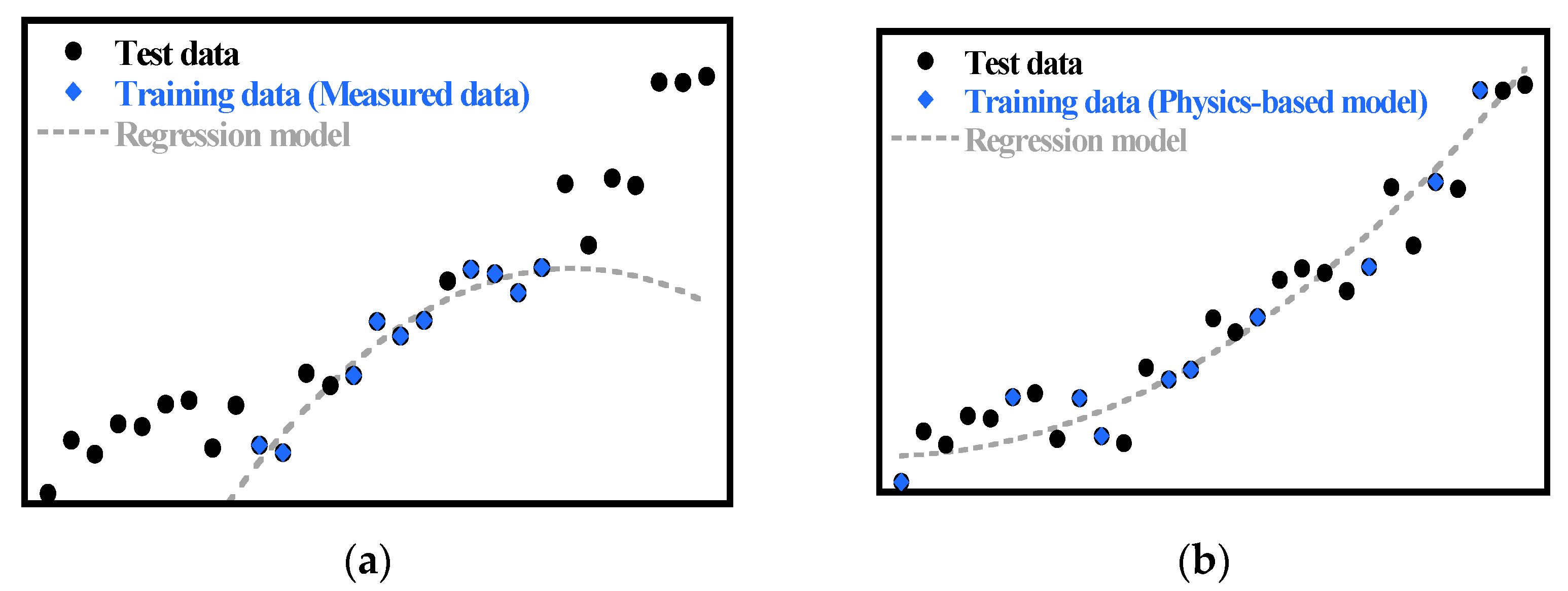
Figure 1. Illustration of the comparison between regression models trained by measured data and a physics-based model: (a) Regression model trained by measured data; (b) Regression model trained by a physics-based model.
Energies 14 08448 g001
Figure 2. Conceptual diagram of distributed generation system and power supply flow.
Energies 14 08448 g002
Figure 3. Annual average (a) weather conditions and (b) demand profile.
Energies 14 08448 g003
Figure 4. Configuration of the gas turbine.
Energies 14 08448 g004
Figure 5. Normalized performance map of the gas turbine: (a) Compressor performance map; (b) Turbine performance map.
Energies 14 08448 g005
Figure 6. Configuration of the bottoming cycle.
Energies 14 08448 g006
Figure 7. Characteristic I-V curve of the photovoltaic module [54].
Energies 14 08448 g007
Figure 8. Variation in the power output of the wind turbine with wind speed [56].
Energies 14 08448 g008
Figure 9. Cycles-to-failure versus DoD for typical deep cycle lead-acid battery [63].
Energies 14 08448 g009
Figure 10. Processes for optimization of the size and operation strategy of the distributed generation system.
Energies 14 08448 g010
Figure 11. Operation strategy process for battery charge/discharge scheduling.
Energies 14 08448 g011
Figure 12. Hourly average SMP in 2018 [75].
Energies 14 08448 g012
Figure 13. (a) MSE according to the number of hidden neurons and training results of the ANN model according to epoch: (b) Gas turbine combined cycle; (c) Photovoltaic module; (d) Wind turbine.
Energies 14 08448 g013
Figure 14. Performance results of the ANN model compared to physics-based model: (a) Gas turbine combined cycle; (b) Photovoltaic module; (c) Wind turbine.
Energies 14 08448 g014
Figure 15. Results of operation strategy according to the gas turbine operation modes: (a) Case 1; (b) Case 2; (c) Case 3.
Energies 14 08448 g015
Table 1. Design parameters and performance of the 15-MW and 5.7-MW gas turbines.
Parameter15-MW5.7-MW
ValueRef.ValueRef.
Compressor inlet mass flow rate49.1 kg/s[35]21.5 kg/s[36]
Compressor pressure ratio17.1[35]12.2[36]
Turbine rotor inlet temperature1180 °C[37]1080 °C[38]
Turbine exhaust gas temperature495 °C[35]510 °C[36]
Gas turbine power15 MW[35]5.7 MW[36]
Gas turbine efficiency0.352[35]0.315[36]
Table 2. Design parameters of the bottoming cycle.
ParameterValueRef.
15-MW GT5.7-MW GT
Steam turbine inlet pressure1687 kPa[39]
Steam turbine inlet temperature225.6 °C[39]
Steam turbine efficiency0.75[39]
Steam turbine outlet pressure100 kPaAssumed
Pinch point temperature difference10 °CAssumed
Exhaust gas temperature170.3 °C167.8 °CResult
Steam turbine power2.6 MW1.2 MWResult
Table 3. Design parameters of the photovoltaic module.
ParameterValueRef.
Open circuit voltage21.6 V[51]
Short circuit current3.27 A
Voltage at the maximum power point17.4 V
Current at the maximum power point3.05 A
Short circuit current temperature coefficient0.0017 A/K
Maximum power output53 W
Series resistance0.2 ohmResult
Shunt resistance305.3 ohmResult
Table 4. Design parameters of the wind turbine.
ParameterValueRef.
Cut-in wind speed3 m/s[56]
Rated wind speed10 m/s
Cut-out wind speed20 m/s
Rotor diameter134 m
Blade length65.5 m
Hub height90 m
Rated power3 MWResult
Blade pitch angle2.3°Result
Table 5. Design parameters of the lead-acid battery.
ParameterValueRef.
Nominal voltage2 V[60]
End-of-charge voltage2.4 V[59]
End-of-discharge voltage1.75 V[60]
Minimum SoC20%[58]
Maximum SoC90%[58]
Charging efficiency89.5%[61]
Discharging efficiency89.5%[61]
Table 6. Input and output datasets for artificial neural network models.
ComponentInput DataOutput Data
ParameterRange
Common T a m b 0–40 °C-
Gas turbine combined cycle W ˙ G T 7.5–16 MW (15-MW GT)/
2.8–6 MW (5.7-MW GT)
W ˙ G T C C ,   m ˙ f
Photovoltaic module G 0–1000 W/m2 W ˙ P V ,   I ,   V
Wind turbine U 0–50 m/s W ˙ W T ,   C p
Table 7. Costs of each device for distributed generation system.
ParameterValueRef.
Installation costGTCC W ˙ G T C C ( 32000 W ˙ G T C C 0.3 + 154 ) $[67]
PVModule: 400 $/kW
BoS: 400 $/kW
[68,70]
WTTurbine: 980 $/kW
BoS: 980 $/kW
[69,71]
Battery300 $/kWh[67]
Inverter194 $/kW[61]
O&M costGTCC3 $/MWh (variable)
0.6 M$/year (fixed)
[50]
Inverter1% of the module cost[61]
PV1% of the turbine cost[69]
WT1% of the battery cost[69]
Fuel cost14.7 won/MJ[72]
Electricity purchase 365 × 1 24 ( P e l ( t ) × | X ( t ) | )
i f   X ( t ) = E ( t ) Q ( t ) > 0 ,   X ( t ) = 0
-
Electricity sales 365 × 1 24 ( X ( t ) × ( S M P + R E C × w P V / W T ) )
i f   X ( t ) = E ( t ) Q ( t ) < 0 ,   X ( t ) = 0
-
Degradation rateGTCC10%[69]
PV0.5%[69]
WT0.5%[69]
Discount rate8%[69]
Interest rate5%[69]
Exchange rate1180 won/$[73]
Project period25 years[66]
Table 8. Electricity price according to time.
Base PriceElectricity Price
Off-peak time7220 won/kW61.6 won/kWh
Mid-peak time84.1 won/kWh
On-peak time114.8 won/kWh
Table 9. Improvement in computational efficiency through artificial neural network model according to the cases.
CaseCalculation TimeRequired Memory
Physics-Based ModelNeural Network ModelPhysics-Based ModelNeural Network Model
Case 1Simple28.06 s0.004716 s423.3 MB175.9 MB
Total2,806,000 s538.7 s
Case 2Simple58.07 s0.002860 s426 MB160.2 MB
Total5,807,000 s259.8 s
Case 3Simple31.74 s0.003612 s387.8 MB168.8 MB
Total3,174,000 s362.5 s
Table 10. Results of the genetic algorithm according to the gas turbine operation mode.
ParameterCase 1Case 2Case 3
PVNumber138,117613,062693,810
Power0.5 MW2.8 MW3.2 MW
WTNumber223
Power1.3 MW1.3 MW1.9 MW
BatteryCapacity7.6 MWh0.2 MWh0.6 MWh
Charged energy6.1 MWh0.15 MWh0.5 MWh
Discharged energy4.9 MWh0.11 MWh0.36 MWh
Electricity sales0 MWh0.09 MWh0.26 MWh
DoD57.9%66.6%66.7%
Cycles1005.9795.8795.0
Objective functionsLCOE0.1947 $/kWh0.1667 $/kWh0.2891 $/kWh
Load sharing rate8.0%17.2%21.5%
Self-consumption rate99.5%99.9%99.9%
Publisher’s Note: MDPI stays neutral with regard to jurisdictional claims in published maps and institutional affiliations.