
Flow-Induced Vibrations of Single and Multiple Heated Circular Cylinders: A Review


Abstract
:1. Introduction
- ▪
- Excitation frequency (fex): vibration frequency of a (self-excited or forced) bluff body
- ▪
- Strouhal frequency (fst): the frequency of vortex shedding for a body at rest
- ▪
- Vortex shedding frequency (fvs): frequency of vortex shedding for a body in motion (self-excited or forced)
- ▪
- Natural frequency (fn): cylinder natural frequency in vacuum
2. Wake Structures
3. Wall Effect for 3D Cylinder
4. Governing Equations for FIV
5. Parameters Affecting FIV
6. Added Mass
7. Mass and Structural Damping
8. Forced Vibrations
9. Lock-In Phenomenon
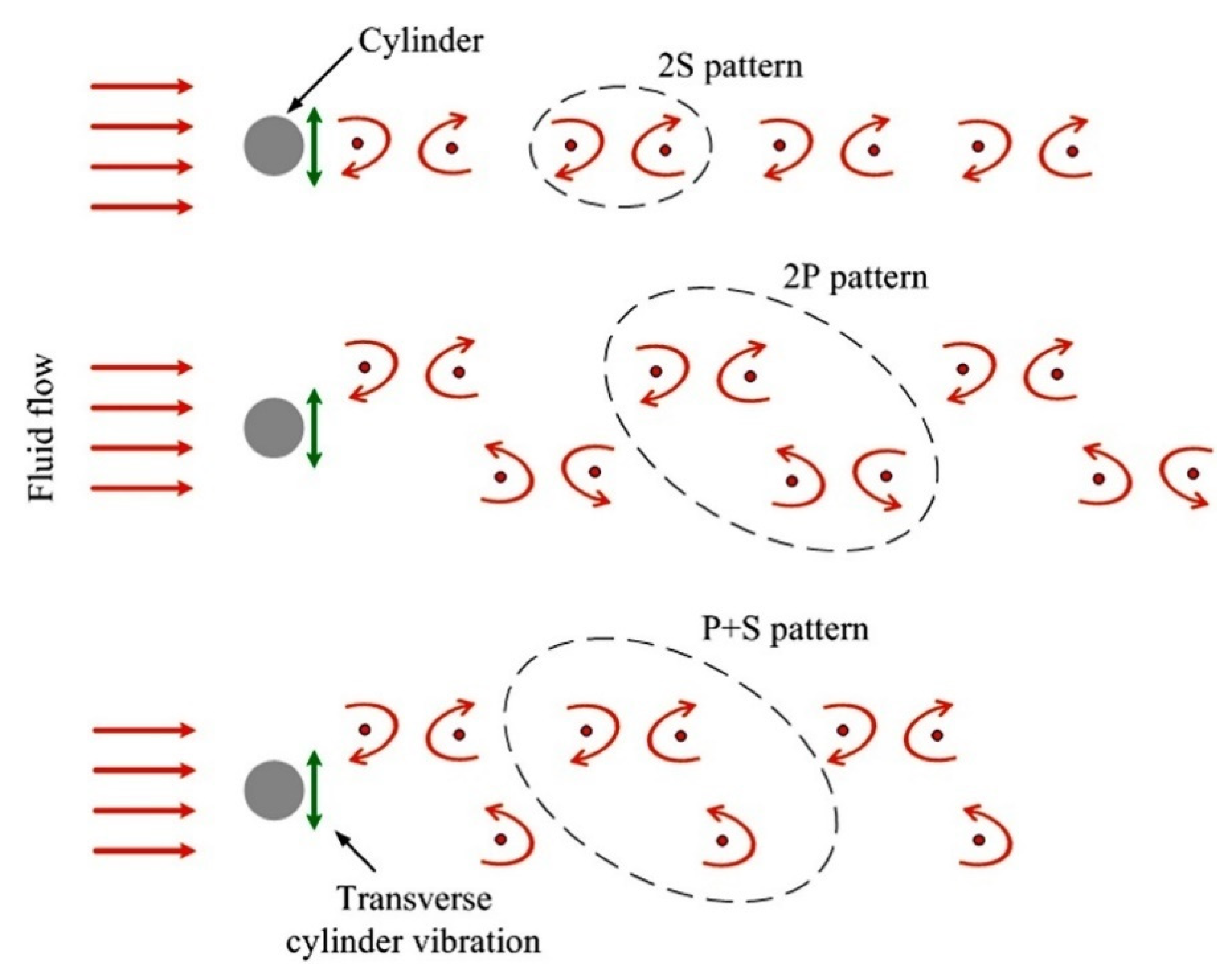
10. Vortex Shedding Patterns/Modes
- ▪
- 2S—two single vortices shed per cycle of shedding
- ▪
- 2P—two pair of vortices shed per cycle of shedding
- ▪
- 2T—two triple vortices shed per cycle of shedding
- ▪
- P+S—a pair of vortices with opposite signs shed at one side and single vortex sheds at the other side of the cylinder [57]
- ▪
- C—Chaotic vortex shedding where a specific pattern cannot be identified [65].
11. Flow over Unheated Single Cylinder
12. Flow over Heated Single Cylinder
13. Tandem, Side-by-Side, and Staggered Cylinders
14. Heated Cylinders
15. 2-DOF Vibration
16. Rough Cylinders
17. Conclusions and Future Prospects
Author Contributions
Funding
Acknowledgments
Conflicts of Interest
Nomenclature
| Symbol | Unit | Definition |
| Re | - | Reynolds number |
| St | - | Strouhal number |
| Nu | - | Nusselt number |
| Ur | - | Reduced velocity |
| fex | Hz | frequency of vibration of a body |
| fst | Hz | vortex shedding frequency of a body at rest |
| fvs | Hz | vortex shedding frequency of a body in motion |
| D | m | dimeter of the cylinder |
| l | m | length of the cylinder |
| U | m/s | freestream velocity |
| ρ | kg/m3 | density of the fluid |
| μ | N s/m2 | dynamic viscosity of the fluid |
| CLf | - | fluctuating lift coefficient |
| 2D | - | two-dimensional |
| 3D | - | three-dimensional |
| AR | - | aspect ratio |
| CL | - | lift coefficient |
| CD | - | drag coefficient |
| CP | - | pressure coefficient |
| m | kg | mass of cylinder |
| k | N/m | spring constant |
| k | m2/s2 | turbulent kinetic energy |
| ε | m2/s3 | rate of dissipation of turbulent kinetic energy |
| kl | m2/s2 | laminar kinetic energy |
| ω | m2/s3 | specific dissipation rate |
| c | N-s/m | damping coefficient |
| x | m | streamwise displacement |
| ẋ | m/s | streamwise velocity |
| ẍ | m/s2 | streamwise acceleration |
| F | N | force |
| y | m | transverse displacement |
| ẏ | m/s | transverse velocity |
| ÿ | m/s2 | transverse acceleration |
| Fl | N | lift force |
| ζ | - | damping ratio |
| fn | Hz | structural natural frequency |
| wn | rad/s | circular natural frequency |
| Fn | - | dimensionless structural natural frequency |
| X | - | dimensionless streamwise displacement |
| Ẋ | - | dimensionless streamwise velocity |
| Ẍ | - | dimensionless streamwise acceleration |
| Y | - | dimensionless transverse displacement |
| Ẏ | - | dimensionless transverse velocity |
| Ÿ | - | dimensionless transverse acceleration |
| m* | - | mass ratio |
| A | m | amplitude of oscillation |
| A/D | - | amplitude to diameter ratio |
| t | s | time |
| G | - | gap ratio |
| FP | - | flow pattern |
| FS | - | flow structures |
| VF | - | velocity field |
| TF | - | temperature field |
| H/D | - | dimensionless transverse pitch |
| rms | - | root mean square |
| h | W/m2K | convective heat transfer coefficient |
| L* | - | dimensionless streamwise center-to-center distance between cylinders |
| T* | - | dimensionless transverse center-to-center distance between cylinders |
| P | - | pitch for staggered cylinders |
| P* | - | dimensionless pitch |
| α | deg | incidence angle for staggered cylinders |
| Ks | m | height of irregular surface |
References
- Lee, A.H.; Campbell, R.L.; Craven, B.A.; Hambric, S.A. Fluid–Structure Interaction Simulation of Vortex-Induced Vibration of a Flexible Hydrofoil. J. Vib. Acoust. 2017, 139, 041001. [Google Scholar] [CrossRef] [Green Version]
- Sarpkaya, T. A critical review of the intrinsic nature of vortex-induced vibrations. J. Fluids Struct. 2004, 19, 389–447. [Google Scholar] [CrossRef]
- Carberry, J.; Sheridan, J.; Rockwell, D. Forces and wake modes of an oscillating cylinder. J. Fluids Struct. 2001, 15, 523–532. [Google Scholar] [CrossRef] [Green Version]
- Williamson, C.; Brown, G. A series in 1/√re to represent the strouhal–reynolds number relationship of the cylinder wake. J. Fluids Struct. 1998, 12, 1073–1085. [Google Scholar] [CrossRef]
- Abdelhamid, T.; Alam, M.; Islam, M. Heat transfer and flow around cylinder: Effect of corner radius and Reynolds number. Int. J. Heat Mass Transf. 2021, 171, 121105. [Google Scholar] [CrossRef]
- Williamson, C.; Roshko, A. Vortex formation in the wake of an oscillating cylinder. J. Fluids Struct. 1988, 2, 355–381. [Google Scholar] [CrossRef]
- Rastan, M.R.; Alam, M. Transition of wake flows past two circular or square cylinders in tandem. Phys. Fluids 2021, 33, 081705. [Google Scholar] [CrossRef]
- Celik, B.; Raisee, M.; Beskok, A. Heat transfer enhancement in a slot channel via a transversely oscillating adiabatic circular cylinder. Int. J. Heat Mass Transf. 2010, 53, 626–634. [Google Scholar] [CrossRef]
- Blevins, R.D.; Gibert, R.J.; Villard, B. Experiments on vibration of heat, exchanger tube arrays in cross flow. In Proceedings of the Transactions of 6th International Conference on Structural Mechanics in Reactor Technology (SMIRT), Paris, France, 17–21 August 1981; p. B6/9. [Google Scholar]
- Klein, U.; Zunkel, A.; Eberle, A. Breakdown of heat exchangers due to erosion corrosion and fretting caused by inappropriate operating conditions. Eng. Fail. Anal. 2014, 43, 271–280. [Google Scholar] [CrossRef]
- Yang, Z.; Ding, L.; Zhang, L.; Yang, L.; He, H. Two degrees of freedom flow-induced vibration and heat transfer of an isothermal cylinder. Int. J. Heat Mass Transf. 2020, 154, 119766. [Google Scholar] [CrossRef]
- Sun, X.; Ye, Z.; Li, J.; Wen, K.; Tian, H. Forced convection heat transfer from a circular cylinder with a flexible fin. Int. J. Heat Mass Transf. 2018, 128, 319–334. [Google Scholar] [CrossRef]
- Zhu, H.; Li, G.; Wang, J. Flow-induced vibration of a circular cylinder with splitter plates placed upstream and downstream individually and simultaneously. Appl. Ocean Res. 2020, 97, 102084. [Google Scholar] [CrossRef]
- Sun, X.; Li, S.; Lin, G.-G.; Zhang, J.-Z. Effects of flow-induced vibration on forced convection heat transfer from two tandem circular cylinders in laminar flow. Int. J. Mech. Sci. 2020, 195, 106238. [Google Scholar] [CrossRef]
- Zhou, Y.; Alam, M. Wake of two interacting circular cylinders: A review. Int. J. Heat Fluid Flow 2016, 62, 510–537. [Google Scholar] [CrossRef]
- Schlichting, H.; Gersten, K. Boundary-Layer Theory; Springer Science & Business Media: Berlin/Heidelberg, Germany, 2003. [Google Scholar]
- Lv, Y.; Sun, L.; Bernitsas, M.M.; Sun, H. A comprehensive review of nonlinear oscillators in hydrokinetic energy harnessing using flow-induced vibrations. Renew. Sustain. Energy Rev. 2021, 150, 111388. [Google Scholar] [CrossRef]
- Wang, J.; Geng, L.; Ding, L.; Zhu, H.; Yurchenko, D. The state-of-the-art review on energy harvesting from flow-induced vibrations. Appl. Energy 2020, 267, 114902. [Google Scholar] [CrossRef]
- Li, D.; Wu, Y.; Da Ronch, A.; Xiang, J. Energy harvesting by means of flow-induced vibrations on aerospace vehicles. Prog. Aerosp. Sci. 2016, 86, 28–62. [Google Scholar] [CrossRef] [Green Version]
- Derakhshandeh, J.; Alam, M. A review of bluff body wakes. Ocean Eng. 2019, 182, 475–488. [Google Scholar] [CrossRef]
- Gabbai, R.; Benaroya, H. An overview of modeling and experiments of vortex-induced vibration of circular cylinders. J. Sound Vib. 2005, 282, 575–616. [Google Scholar] [CrossRef]
- Bearman, P.W. Vortex Shedding from Oscillating Bluff Bodies. Annu. Rev. Fluid Mech. 1984, 16, 195–222. [Google Scholar] [CrossRef]
- Williamson, C.; Govardhan, R. Vortex-induced vibrations. Annu. Rev. Fluid Mech. 2004, 36, 413–455. [Google Scholar] [CrossRef] [Green Version]
- Sumner, D. Two circular cylinders in cross-flow: A review. J. Fluids Struct. 2010, 26, 849–899. [Google Scholar] [CrossRef]
- Weaver, D.; Fitzpatrick, J. A review of cross-flow induced vibrations in heat exchanger tube arrays. J. Fluids Struct. 1988, 2, 73–93. [Google Scholar] [CrossRef]
- Païdoussis, M. A review of flow-induced vibrations in reactors and reactor components. Nucl. Eng. Des. 1983, 74, 31–60. [Google Scholar] [CrossRef]
- Parkinson, G. Phenomena and modelling of flow-induced vibrations of bluff bodies. Prog. Aerosp. Sci. 1989, 26, 169–224. [Google Scholar] [CrossRef]
- Miwa, S.; Mori, M.; Hibiki, T. Two-phase flow induced vibration in piping systems. Prog. Nucl. Energy 2015, 78, 270–284. [Google Scholar] [CrossRef]
- Hong, K.-S.; Shah, U.H. Vortex-induced vibrations and control of marine risers: A review. Ocean Eng. 2018, 152, 300–315. [Google Scholar] [CrossRef]
- Liu, G.; Li, H.; Qiu, Z.; Leng, D.; Li, Z.; Li, W. A mini review of recent progress on vortex-induced vibrations of marine risers. Ocean Eng. 2019, 195, 106704. [Google Scholar] [CrossRef]
- Fehér, R.; Avila, J.J. Vortex-induced vibrations model with 2 degrees of freedom of rigid cylinders near a plane boundary based on wake oscillator. Ocean Eng. 2021, 234, 108938. [Google Scholar] [CrossRef]
- Alam, M.; Abdelhamid, T.; Sohankar, A. Effect of cylinder corner radius and attack angle on heat transfer and flow topology. Int. J. Mech. Sci. 2020, 175, 105566. [Google Scholar] [CrossRef]
- Williamson, C. Three-dimensional vortex dynamics in bluff body wakes. Exp. Therm. Fluid Sci. 1996, 12, 150–168. [Google Scholar] [CrossRef]
- Roshko, A. Experiments on the flow past a circular cylinder at very high Reynolds number. J. Fluid Mech. 1961, 10, 345–356. [Google Scholar] [CrossRef] [Green Version]
- Coutanceau, M.; Defaye, J.-R. Circular Cylinder Wake Configurations: A Flow Visualization Survey. Appl. Mech. Rev. 1991, 44, 255–305. [Google Scholar] [CrossRef]
- ALAM, M.; Zhou, Y.; Wang, X.W. The wake of two side-by-side square cylinders. J. Fluid Mech. 2011, 669, 432–471. [Google Scholar] [CrossRef] [Green Version]
- Alam, M. The aerodynamics of a cylinder submerged in the wake of another. J. Fluids Struct. 2014, 51, 393–400. [Google Scholar] [CrossRef]
- Bai, H.; Alam, M. Dependence of square cylinder wake on Reynolds number. Phys. Fluids 2018, 30, 015102. [Google Scholar] [CrossRef]
- Zdravkovich, M.M. Flow Around Circular Cylinders Volume 1: Fundamentals; Oxford University Press: Oxford, UK, 1997. [Google Scholar]
- Norberg, C. Fluctuating lift on a circular cylinder: Review and new measurements. J. Fluids Struct. 2003, 17, 57–96. [Google Scholar] [CrossRef]
- Zdravkovich, M. Different modes of vortex shedding: An overview. J. Fluids Struct. 1996, 10, 427–437. [Google Scholar] [CrossRef]
- Williamson, C.H.K. Oblique and parallel modes of vortex shedding in the wake of a circular cylinder at low Reynolds numbers. J. Fluid Mech. 1989, 206, 579–627. [Google Scholar] [CrossRef] [Green Version]
- Gerich, D.; Eckelmann, H. Influence of end plates and free ends on the shedding frequency of circular cylinders. J. Fluid Mech. 1982, 122, 109–121. [Google Scholar] [CrossRef]
- Tritton, D.J. Experiments on the flow past a circular cylinder at low Reynolds numbers. J. Fluid Mech. 1959, 6, 547–567. [Google Scholar] [CrossRef]
- Williamson, C. Advances in our understanding of vortex dynamics in bluff body wakes. J. Wind Eng. Ind. Aerodyn. 1997, 69–71, 3–32. [Google Scholar] [CrossRef]
- Ozgoren, M.; Pinar, E.; Sahin, B.; Akilli, H. Comparison of flow structures in the downstream region of a cylinder and sphere. Int. J. Heat Fluid Flow 2011, 32, 1138–1146. [Google Scholar] [CrossRef]
- Ong, L.; Wallace, J. The velocity field of the turbulent very near wake of a circular cylinder. Exp. Fluids 1996, 20, 441–453. [Google Scholar] [CrossRef]
- Kiya, M.; Tamura, H.; Arie, M. Vortex shedding from a circular cylinder in moderate-Reynolds-number shear flow. J. Fluid Mech. 1980, 101, 721–735. Available online: https://www.cambridge.org/core/journals/journal-of-fluid-mechanics/article/abs/vortex-shedding-from-a-circular-cylinder-in-moderatereynoldsnumber-shear-flow/8C809D0CA910AC165F346250D19E610C (accessed on 10 November 2021). [CrossRef]
- Alam, M.; Zhou, Y. Alternative drag coefficient in the wake of an isolated bluff body. Phys. Rev. E 2008, 78, 036320. [Google Scholar] [CrossRef] [Green Version]
- Liang, C.; Papadakis, G. Large eddy simulation of pulsating flow over a circular cylinder at subcritical Reynolds number. Comput. Fluids 2007, 36, 299–312. [Google Scholar] [CrossRef]
- Blevins, R.D. Flow-Induced Vibration. 1990. Available online: https://www.osti.gov/biblio/6168070-flow-induced-vibration (accessed on 10 November 2021).
- Bearman, P.W. On vortex shedding from a circular cylinder in the critical Reynolds number régime. J. Fluid Mech. 1969, 37, 577–585. [Google Scholar] [CrossRef]
- Williamson, C.H.K. The existence of two stages in the transition to three-dimensionality of a cylinder wake. Phys. Fluids 1988, 31, 3165. [Google Scholar] [CrossRef]
- Szepessy, S.; Bearman, P.W. Aspect ratio and end plate effects on vortex shedding from a circular cylinder. J. Fluid Mech. 1992, 234, 191–217. [Google Scholar] [CrossRef]
- Mittal, S.; Sidharth, G. Steady forces on a cylinder with oblique vortex shedding. J. Fluids Struct. 2014, 44, 310–315. [Google Scholar] [CrossRef]
- Izadpanah, E.; Amini, Y.; Ashouri, A. A comprehensive investigation of vortex induced vibration effects on the heat transfer from a circular cylinder. Int. J. Therm. Sci. 2018, 125, 405–418. [Google Scholar] [CrossRef]
- Nepali, R.; Ping, H.; Han, Z.; Zhou, D.; Yang, H.; Tu, J.; Zhao, Y.; Bao, Y. Two-degree-of-freedom vortex-induced vibrations of two square cylinders in tandem arrangement at low Reynolds numbers. J. Fluids Struct. 2020, 97, 102991. [Google Scholar] [CrossRef]
- Zhou, D.; Han, Z.; Tu, J.; Sun, W. Flow characteristics and dynamic responses of a rear circular cylinder behind the square cylinder with different side lengths. J. Vibroeng. 2017, 19, 2956–2975. [Google Scholar] [CrossRef] [Green Version]
- Chen, W.; Ji, C.; Xu, D. Vortex-induced vibrations of two side-by-side circular cylinders with two degrees of freedom in laminar cross-flow. Comput. Fluids 2019, 193, 104288. [Google Scholar] [CrossRef]
- Chen, W.; Ji, C.; Xu, D.; Zhang, Z.; Wei, Y. Flow-induced vibrations of an equilateral triangular prism at various angles of attack. J. Fluids Struct. 2020, 97, 103099. [Google Scholar] [CrossRef]
- Papaioannou, G.; Yue, D.; Triantafyllou, M.; Karniadakis, G. On the effect of spacing on the vortex-induced vibrations of two tandem cylinders. J. Fluids Struct. 2008, 24, 833–854. [Google Scholar] [CrossRef]
- Han, Z.; Zhou, D.; He, T.; Tu, J.; Li, C.; Kwok, K.C.; Fang, C. Flow-induced vibrations of four circular cylinders with square arrangement at low Reynolds numbers. Ocean Eng. 2015, 96, 21–33. [Google Scholar] [CrossRef]
- Chung, M.-H. On characteristics of two-degree-of-freedom vortex induced vibration of two low-mass circular cylinders in proximity at low Reynolds number. Int. J. Heat Fluid Flow 2017, 65, 220–245. [Google Scholar] [CrossRef]
- Wang, H.; Yu, G.; Yang, W. Numerical Study of Vortex-Induced Vibrations of Three Circular Cylinders in Equilateral-Triangle Arrangement. Adv. Mech. Eng. 2013, 5, 287923. [Google Scholar] [CrossRef] [Green Version]
- Wang, H.; Yang, W.; Nguyen, K.D.; Yu, G. Wake-induced vibrations of an elastically mounted cylinder located downstream of a stationary larger cylinder at low Reynolds numbers. J. Fluids Struct. 2014, 50, 479–496. [Google Scholar] [CrossRef]
- Yu, K.R.; Étienne, S.; Scolan, Y.-M.; Hay, A.; Fontaine, E.; Pelletier, D. Flow-induced vibrations of in-line cylinder arrangements at low Reynolds numbers. J. Fluids Struct. 2016, 60, 37–61. [Google Scholar] [CrossRef] [Green Version]
- Zhao, M.; Cui, Z.; Kwok, K.; Zhang, Y. Wake-induced vibration of a small cylinder in the wake of a large cylinder. Ocean Eng. 2016, 113, 75–89. [Google Scholar] [CrossRef]
- Ashouri, A.; Izadpanah, E.; Hekmat, M.H.; Amini, Y. Numerical investigation on two-degree-of-freedom vortex-induced vibration of a circular cylinder in power-law fluids. J. Non-Newton. Fluid Mech. 2021, 292, 104535. [Google Scholar] [CrossRef]
- Zou, Q.; Ding, L.; Zou, R.; Kong, H.; Wang, H.; Zhang, L. Two-degree-of-freedom flow-induced vibration of two circular cylinders with constraint for different arrangements. Ocean Eng. 2021, 225, 108806. [Google Scholar] [CrossRef]
- Stokes, G.G. On the Effect of the Internal Friction of Fluids on the Motion of Pendulums. In Transactions of the Cambridge Philosophical Society; Cambridge University Press: Cambridge, UK, 1851; Volume 9, p. 8. [Google Scholar]
- Vikestad, K.; Vandiver, J.; Larsen, C. Added mass and oscillation frequency for a circular cylinder subjected to vortex-induced vibrations and external disturbance. J. Fluids Struct. 2000, 14, 1071–1088. [Google Scholar] [CrossRef]
- Koopmann, G.H. On the Wind-Induced Vibrations of Circular Cylinders. Master’s Thesis, Catholic University of America, Washington, DC, USA, 1967. [Google Scholar]
- Alam, M. Effects of Mass and Damping on Flow-Induced Vibration of a Cylinder Interacting with the Wake of Another Cylinder at High Reduced Velocities. Energies 2021, 14, 5148. [Google Scholar] [CrossRef]
- Khalak, A.; Williamson, C. Motions, forces and mode transitions in vortex-induced vibrations at low mass-damping. J. Fluids Struct. 1999, 13, 813–851. [Google Scholar] [CrossRef]
- Gao, Y.; Liu, L.; Zou, L.; Zhang, Z.; Yang, B. Effect of surface roughness on vortex-induced vibrations of a freely vibrating cylinder near a stationary plane wall. Ocean Eng. 2020, 198, 106837. [Google Scholar] [CrossRef]
- Facchinetti, M.; de Langre, E.; Biolley, F. Coupling of structure and wake oscillators in vortex-induced vibrations. J. Fluids Struct. 2004, 19, 123–140. [Google Scholar] [CrossRef]
- Feng, C.C. The Measurement of Vortex Induced Effects in Flow Past Stationary and Oscillating Circular and D-Section Cylinders. Master’s Thesis, University of British Columbia, Vancouver, BC, Canada, 1968. [Google Scholar] [CrossRef]
- Khalak, A.; Williamson, C. Fluid forces and dynamics of a hydroelastic structure with very low mass and damping. J. Fluids Struct. 1997, 11, 973–982. [Google Scholar] [CrossRef]
- Parkinson, G.V. Wind-induced instability of structures. Philos. Trans. R. Soc. Lond. Ser. A Math. Phys. Sci. 1971, 269, 395–413. [Google Scholar] [CrossRef]
- Carberry, J.; Sheridan, J.; Rockwell, D. Controlled oscillations of a cylinder: Forces and wake modes. J. Fluid Mech. 2005, 538, 31–69. [Google Scholar] [CrossRef]
- Cheng, M.; Moretti, P.M. Lock-in phenomena on a single cylinder with forced transverse vibration. In Proceedings of the ASME PVP-206, Flow-Induced Vibration and Wear, San Diego, CA, USA, 23–27 June 1991; pp. 129–133. [Google Scholar]
- Krishnamoorthy, S.; Price, S.; Païdoussis, M. Cross-flow past an oscillating circular cylinder: Synchronization phenomena in the near wake. J. Fluids Struct. 2001, 15, 955–980. [Google Scholar] [CrossRef]
- Sarpkaya, T. Taylor–Gortler instability and separation on a cylinder in sinusoidally oscillating flow. In Proceedings of the IUTAM Symposium on Unsteady Flows, Toulouse, France, 8–12 April 2002. [Google Scholar]
- Sarpkaya, T.; Butterworth, W. Separation Points on a Cylinder in Oscillating Flow. J. Offshore Mech. Arct. Eng. 1992, 114, 28–35. [Google Scholar] [CrossRef]
- Rodriguez, O.; Pruvost, J. Wakes of an oscillating cylinder. In Proceedings of the IUTAM Symposium, Marseille, France, 13–16 June 2000. [Google Scholar]
- Olinger, D.J.; Sreenivasan, K.R. Nonlinear dynamics of the wake of an oscillating cylinder. Phys. Rev. Lett. 1988, 60, 797–800. [Google Scholar] [CrossRef]
- Brika, D.; Laneville, A. Vortex-induced vibrations of a long flexible circular cylinder. J. Fluid Mech. 1993, 250, 481–508. [Google Scholar] [CrossRef]
- Govardhan, R.; Williamson, C.H.K. Modes of vortex formation and frequency response of a freely vibrating cylinder. J. Fluid Mech. 2000, 420, 85–130. [Google Scholar] [CrossRef]
- Blackburn, H.; Govardhan, R.; Williamson, C. A complementary numerical and physical investigation of vortex-induced vibration. J. Fluids Struct. 2001, 15, 481–488. [Google Scholar] [CrossRef] [Green Version]
- Wanderley, J.B.; Soares, L.F.N. Vortex-induced vibration on a two-dimensional circular cylinder with low Reynolds number and low mass-damping parameter. Ocean Eng. 2015, 97, 156–164. [Google Scholar] [CrossRef]
- Chung, M.-H. Transverse vortex-induced vibration of spring-supported circular cylinder translating near a plane wall. Eur. J. Mech.-B/Fluids 2016, 55, 88–103. [Google Scholar] [CrossRef]
- Raghavan, K.; Bernitsas, M. Experimental investigation of Reynolds number effect on vortex induced vibration of rigid circular cylinder on elastic supports. Ocean Eng. 2011, 38, 719–731. [Google Scholar] [CrossRef]
- King, R.; Prosser, M.; Johns, D. On vortex excitation of model piles in water. J. Sound Vib. 1973, 29, 169–188. [Google Scholar] [CrossRef]
- King, R. Vortex Excited Structural Oscillations of a Circular Cylinder in Steady Currents. (OTC #1948 Paper). 1, Article OTC #1948 Paper. 1974. Available online: https://trid.trb.org/view/25013 (accessed on 10 November 2021).
- Wootton, L.R.; Warner, M.H.; Cooper, D.H. Some Aspects of Oscillations of Full Scale Piles, in Flow Induced Structural Vibrations; Naudascher, E., Ed.; Springer: Berlin/Heidelberg, Germany, 1974; pp. 587–601. [Google Scholar]
- Karanth, D.; Rankin, G.W.; Sridhar, K. Computational study of flow past a cylinder with combined in-line and transverse oscillation. Comput. Mech. 1995, 16, 1–10. [Google Scholar] [CrossRef]
- Okajima, A.; Kosugi, T.; Nakamura, A. Flow-Induced Vibration of Bluff Bodies. Experiments on Flow-Induced In-Line Oscillation of a Circular Cylinder in a Water Tunnel. 1st-Report, The Difference of the Response Characteristics When a Cylinder is Elastically Supported at Both Ends and Cantilevered. JSME Int. J. Ser. B 2001, 44, 695–704. [Google Scholar] [CrossRef] [Green Version]
- Okajima, A.; Kosugi, T.; Nakamura, A. Flow-Induced In-Line Oscillation of a Circular Cylinder in a Water Tunnel. J. Press. Vessel. Technol. 2001, 124, 89–96. [Google Scholar] [CrossRef]
- Nakamura, A.; Okajima, A.; Kosugi, T. Flow-Induced Vibration of Bluff Bodies. Experiments on Flow-Induced In-Line Oscillation of a Circular Cylinder in a Water Tunnel. 2nd Report, Influence of the Aspect Ratio of a Cantilevered Circular Cylinder. JSME Int. J. Ser. B 2001, 44, 705–711. [Google Scholar] [CrossRef] [Green Version]
- Sakai, T.; Iwata, K.; Morishita, M.; Kitamura, S. Flow-Induced Vibration of Bluff Bodies. Vortex-Induced Vibration of a Cantilever Circular Cylinder in Super-Critical Reynolds Number Flow and Its Suppression by Structure Damping. JSME Int. J. Ser. B 2001, 44, 712–720. [Google Scholar] [CrossRef] [Green Version]
- Bai, W. Numerical simulation of turbulent flow around a forced moving circular cylinder on cut cells. J. Hydrodyn. 2013, 25, 829–838. [Google Scholar] [CrossRef]
- Al-Mdallal, Q.; Lawrence, K.; Kocabiyik, S. Forced streamwise oscillations of a circular cylinder: Locked-on modes and resulting fluid forces. J. Fluids Struct. 2007, 23, 681–701. [Google Scholar] [CrossRef]
- Norberg, C. An experimental investigation of the flow around a circular cylinder: Influence of aspect ratio. J. Fluid Mech. 1994, 258, 287–316. [Google Scholar] [CrossRef]
- Norberg, C. Flow around a circular cylinder: Aspects of fluctuating lift. J. Fluids Struct. 2001, 15, 459–469. [Google Scholar] [CrossRef]
- Kravchenko, A.G.; Moin, P. Numerical studies of flow over a circular cylinder at ReD=3900. Phys. Fluids 2000, 12, 403–417. [Google Scholar] [CrossRef]
- Ma, X.; Karamanos, G.-S.; Karniadakis, G.E. Dynamics and low-dimensionality of a turbulent near wake. J. Fluid Mech. 2000, 410, 29–65. [Google Scholar] [CrossRef] [Green Version]
- Park, C.-W.; Lee, S.-J. Free end effects on the near wake flow structure behind a finite circular cylinder. J. Wind Eng. Ind. Aerodyn. 2000, 88, 231–246. [Google Scholar] [CrossRef]
- Singh, S.; Mittal, S. Vortex-induced oscillations at low Reynolds numbers: Hysteresis and vortex-shedding modes. J. Fluids Struct. 2005, 20, 1085–1104. [Google Scholar] [CrossRef]
- Kim, J.; Choi, H. Distributed forcing of flow over a circular cylinder. Phys. Fluids 2005, 17, 033103. [Google Scholar] [CrossRef]
- Alam, M.; Fu, S.; Zhou, Y. Generation of vortices by a streamwise oscillating cylinder. J. Vis. 2007, 10, 65–73. [Google Scholar] [CrossRef]
- Marquart, J.; Endicott, D.; Dear, C. CFD Investigation of the Drag Effects of Heating and Cooling Cylinders in Crossflow. In Proceedings of the 6th AIAA Flow Control Conference, New Orleans, LA, USA, 25–28 June 2012. [Google Scholar] [CrossRef]
- Zhao, M.; Cheng, L.; An, H.; Lu, L. Three-dimensional numerical simulation of vortex-induced vibration of an elastically mounted rigid circular cylinder in steady current. J. Fluids Struct. 2014, 50, 292–311. [Google Scholar] [CrossRef]
- Kim, S.; Alam, M.; Maiti, D.K. Wake and suppression of flow-induced vibration of a circular cylinder. Ocean Eng. 2018, 151, 298–307. [Google Scholar] [CrossRef]
- Cheng, C.-H.; Chen, H.-N.; Aung, W. Experimental Study of the Effect of Transverse Oscillation on Convection Heat Transfer From a Circular Cylinder. J. Heat Transf. 1997, 119, 474–482. [Google Scholar] [CrossRef]
- Gau, C.; Wu, J.M.; Liang, C.Y. Heat Transfer Enhancement and Vortex Flow Structure Over a Heated Cylinder Oscillating in the Crossflow Direction. J. Heat Transf. 1999, 121, 789–795. [Google Scholar] [CrossRef]
- Baratchi, F.; Saghafian, M.; Baratchi, B. Numerical Investigation on Lock-In Condition and Convective Heat Transfer From an Elastically Supported Cylinder in a Cross Flow. J. Fluids Eng. 2013, 135, 031103. [Google Scholar] [CrossRef]
- Knudsen, J.D.; Katz, D.L. Fluid Dynamics and Heat Transfer; McGraw Hill: New York, NY, USA, 1958. [Google Scholar]
- Žukauskas, A. Heat Transfer from Tubes in Crossflow. In Advances in Heat Transfer; Elsevier: Amsterdam, The Netherlands, 1972; Volume 8, pp. 93–160. [Google Scholar] [CrossRef]
- Churchill, S.W.; Bernstein, M. A Correlating Equation for Forced Convection From Gases and Liquids to a Circular Cylinder in Crossflow. J. Heat Transf. 1977, 99, 300–306. [Google Scholar] [CrossRef]
- Wang, A.-B.; Trávníček, Z. On the linear heat transfer correlation of a heated circular cylinder in laminar crossflow using a new representative temperature concept. Int. J. Heat Mass Transf. 2001, 44, 4635–4647. [Google Scholar] [CrossRef]
- Baranyi, L.; Szabó, S.; Bolló, B.; Bordás, R. Analysis of low Reynolds number flow around a heated circular cylinder. J. Mech. Sci. Technol. 2009, 23, 1829–1834. [Google Scholar] [CrossRef] [Green Version]
- Nakamura, H.; Igarashi, T. Unsteady heat transfer from a circular cylinder for Reynolds numbers from 3000 to 15,000. Int. J. Heat Fluid Flow 2004, 25, 741–748. [Google Scholar] [CrossRef]
- Salimipour, E. A numerical study on the fluid flow and heat transfer from a horizontal circular cylinder under mixed convection. Int. J. Heat Mass Transf. 2018, 131, 365–374. [Google Scholar] [CrossRef]
- Schneider, G.E.; Zedan, M. A modified strongly implicit procedure for the numerical solution of field problems. Numer. Heat Transf. 1981, 4, 1–19. [Google Scholar] [CrossRef]
- Witte, A.; Cabrera, A.; Polifke, W. Identification of the heat transfer frequency response in pulsating laminar and subcritical flow across a cylinder. J. Phys. Conf. Ser. 2016, 745, 032055. [Google Scholar] [CrossRef]
- Jogee, S.; Prasad, B.; Anupindi, K. Large-eddy simulation of non-isothermal flow over a circular cylinder. Int. J. Heat Mass Transf. 2020, 151, 119426. [Google Scholar] [CrossRef]
- Baughn, J.W.; Elderkin, M.J.; McKillop, A.A. Heat Transfer From a Single Cylinder, Cylinders in Tandem, and Cylinders in the Entrance Region of a Tube Bank With a Uniform Heat Flux. J. Heat Transf. 1986, 108, 386–391. [Google Scholar] [CrossRef]
- Matsumura, M.; Antonia, R.A. Momentum and heat transport in the turbulent intermediate wake of a circular cylinder. J. Fluid Mech. 1993, 250, 651–668. [Google Scholar] [CrossRef]
- Antonia, R.; Zhou, Y.; Matsumura, M. Spectral characteristics of momentum and heat transfer in the turbulent wake of a circular cylinder. Exp. Therm. Fluid Sci. 1993, 6, 371–375. [Google Scholar] [CrossRef]
- Buyruk, E. Heat Transfer and Flow Structures Around Circular Cylinders in Cross-Flow. J. Eng. Environ. Sci. 1999, 23, 299–315. [Google Scholar]
- Kumar, R.S.; Jayavel, S. Influence of flow shedding frequency on convection heat transfer from bank of circular tubes in heat exchangers under cross flow. Int. J. Heat Mass Transf. 2016, 105, 376–393. [Google Scholar] [CrossRef]
- Ali, U.; Islam, M.; Janajreh, I. Dynamic Behavior of a Streamwise Oscillating Heated Cylinder. In Proceedings of the ASME 2021 Heat Transfer Summer Conference, Online, 16–18 June 2021; p. V001T01A009. [Google Scholar] [CrossRef]
- Zafar, F.; Alam, M. Flow structure around and heat transfer from cylinders modified from square to circular. Phys. Fluids 2019, 31, 083604. [Google Scholar] [CrossRef]
- Ali, U.; Islam, M.; Janajreh, I. Heated Circular Cylinder Subjected to Forced Spanwise Oscillations. In Proceedings of the ASME 2021 International Mechanical Engineering Congress and Exposition, Virtual Online, 1–5 November 2021. [Google Scholar]
- Homsi, R.; Islam, D.; Fatt, Y.Y.; Janajreh, I. Flow dynamics over a heated cylinder subjected to high temperature ratios. Case Stud. Therm. Eng. 2021, 27, 101357. [Google Scholar] [CrossRef]
- Zdravkovich, M. The effects of interference between circular cylinders in cross flow. J. Fluids Struct. 1987, 1, 239–261. [Google Scholar] [CrossRef]
- Lin, J.-C.; Yang, Y.; Rockwell, D. Flow past two cylinders in tandem: Instantaneous and averaged flow structure. J. Fluids Struct. 2002, 16, 1059–1071. [Google Scholar] [CrossRef]
- Zhou, Y.; Yiu, M.W. Flow structure, momentum and heat transport in a two-tandem-cylinder wake. J. Fluid Mech. 2006, 548, 17–48. [Google Scholar] [CrossRef] [Green Version]
- Igarashi, T. Characteristics of the Flow around Two Circular Cylinders Arranged in Tandem: 1st Report. Bull. JSME 1981, 24, 323–331. [Google Scholar] [CrossRef]
- Alam, M.; Meyer, J. Global aerodynamic instability of twin cylinders in cross flow. J. Fluids Struct. 2013, 41, 135–145. [Google Scholar] [CrossRef] [Green Version]
- Qin, B.; Alam, M.; Zhou, Y. Two tandem cylinders of different diameters in cross-flow: Flow-induced vibration. J. Fluid Mech. 2017, 829, 621–658. [Google Scholar] [CrossRef]
- Kim, S.; Alam, M.; Sakamoto, H.; Zhou, Y. Flow-induced vibrations of two circular cylinders in tandem arrangement. Part 1: Characteristics of vibration. J. Wind Eng. Ind. Aerodyn. 2009, 97, 304–311. [Google Scholar] [CrossRef]
- Kim, S.; Alam, M.; Sakamoto, H.; Zhou, Y. Flow-induced vibration of two circular cylinders in tandem arrangement. Part 2: Suppression of vibrations. J. Wind Eng. Ind. Aerodyn. 2009, 97, 312–319. [Google Scholar] [CrossRef]
- Xu, W.; Ji, C.; Sun, H.; Ding, W.; Bernitsas, M.M. Flow-induced vibration of two elastically mounted tandem cylinders in cross-flow at subcritical Reynolds numbers. Ocean Eng. 2019, 173, 375–387. [Google Scholar] [CrossRef]
- Sun, H.; Ma, C.; Kim, E.S.; Nowakowski, G.; Mauer, E.; Bernitsas, M.M. Flow-induced vibration of tandem circular cylinders with selective roughness: Effect of spacing, damping and stiffness. Eur. J. Mech.-B/Fluids 2018, 74, 219–241. [Google Scholar] [CrossRef]
- Huera-Huarte, F.; Jiménez-González, J. Effect of diameter ratio on the flow-induced vibrations of two rigidly coupled circular cylinders in tandem. J. Fluids Struct. 2019, 89, 96–107. [Google Scholar] [CrossRef]
- Zhao, M.; Cheng, L.; Teng, B.; Dong, G. Hydrodynamic forces on dual cylinders of different diameters in steady currents. J. Fluids Struct. 2006, 23, 59–83. [Google Scholar] [CrossRef]
- Alam, M.; Moriya, M.; Takai, K.; Sakamoto, H. Fluctuating fluid forces acting on two circular cylinders in a tandem arrangement at a subcritical Reynolds number. J. Wind Eng. Ind. Aerodyn. 2003, 91, 139–154. [Google Scholar] [CrossRef]
- Assi, G.R.S.; Meneghini, J.R.; Aranha, J.; Bearman, P.; Casaprima, E. Experimental investigation of flow-induced vibration interference between two circular cylinders. J. Fluids Struct. 2006, 22, 819–827. [Google Scholar] [CrossRef]
- Borazjani, I.; Sotiropoulos, F. Vortex-induced vibrations of two cylinders in tandem arrangement in the proximity–wake interference region. J. Fluid Mech. 2009, 621, 321–364. [Google Scholar] [CrossRef] [Green Version]
- Brika, D.; Laneville, A. The flow interaction between a stationary cylinder and a downstream flexible cylinder. J. Fluids Struct. 1999, 13, 579–606. [Google Scholar] [CrossRef]
- Gao, Y.; Sun, Z.; Tan, D.; Yu, D.; Tan, S.K. Wake flow behaviour behind a smaller cylinder oscillating in the wake of an upstream stationary cylinder. Fluid Dyn. Res. 2014, 46, 025505. [Google Scholar] [CrossRef]
- Kitagawa, T.; Ohta, H. Numerical investigation on flow around circular cylinders in tandem arrangement at a subcritical Reynolds number. J. Fluids Struct. 2008, 24, 680–699. [Google Scholar] [CrossRef]
- Kondo, N.; Matsukuma, D. Numerical simulation for flow around two circular cylinders in tandem. Int. J. Comput. Fluid Dyn. 2005, 19, 277–288. [Google Scholar] [CrossRef]
- Carmo, B.S.; Assi, G.R.; Meneghini, J.R. Computational simulation of the flow-induced vibration of a circular cylinder subjected to wake interference. J. Fluids Struct. 2013, 41, 99–108. [Google Scholar] [CrossRef]
- Brika, D.; Laneville, A. Wake interference between two circular cylinders. J. Wind Eng. Ind. Aerodyn. 1997, 72, 61–70. [Google Scholar] [CrossRef]
- Sumner, D.; Wong, S.; Price, S.; Païdoussis, M. Fluid behaviour of side-by-side circular cylinders in steady cross-flow. J. Fluids Struct. 1999, 13, 309–338. [Google Scholar] [CrossRef]
- Sumner, D.; Price, S.J.; Païdoussis, M.P. Flow-pattern identification for two staggered circular cylinders in cross-flow. J. Fluid Mech. 2000, 411, 263–303. [Google Scholar] [CrossRef] [Green Version]
- Zhou, Y.; So, R.; Liu, M.; Zhang, H. Complex turbulent wakes generated by two and three side-by-side cylinders. Int. J. Heat Fluid Flow 2000, 21, 125–133. [Google Scholar] [CrossRef]
- Farrant, T.; Tan, M.; Price, W. A cell boundary element method applied to laminar vortex-shedding from arrays of cylinders in various arrangements. J. Fluids Struct. 2000, 14, 375–402. [Google Scholar] [CrossRef]
- Meneghini, J.R.; Saltara, F.; Siqueira, C.L.R.; Ferrari, J. Numerical simulation of flow interference between two circular cylinders in tandem and side-by-side arrangements. J. Fluids Struct. 2001, 15, 327–350. [Google Scholar] [CrossRef]
- Ozono, S.; Oda, J.; Yoshida, Y.; Wakasugi, Y. Critical nature of the base pressure of the upstream circular cylinder in two staggered ones in cross-flow. Theor. Appl. Mech. Jpn. 2001, 50, 335–340. [Google Scholar]
- Zhou, Y.; Zhang, H.J.; Yiu, M.W. The turbulent wake of two side-by-side circular cylinders. J. Fluid Mech. 2002, 458, 303–332. [Google Scholar] [CrossRef] [Green Version]
- Wang, Z.; Zhou, Y.; Li, H. Flow-visualization of a two side-by-side cylinder wake. J. Flow Vis. Image Process. 2002, 9, 16. [Google Scholar] [CrossRef]
- Xu, S.J.; Zhou, Y.; So, R.M.C. Reynolds number effects on the flow structure behind two side-by-side cylinders. Phys. Fluids 2003, 15, 1214–1219. [Google Scholar] [CrossRef]
- Chen, L.; Tu, J.; Yeoh, G. Numerical simulation of turbulent wake flows behind two side-by-side cylinders. J. Fluids Struct. 2003, 18, 387–403. [Google Scholar] [CrossRef]
- Jester, W.; Kallinderis, Y. Numerical study of incompressible flow about fixed cylinder pairs. J. Fluids Struct. 2003, 17, 561–577. [Google Scholar] [CrossRef]
- Kang, S. Characteristics of flow over two circular cylinders in a side-by-side arrangement at low Reynolds numbers. Phys. Fluids 2003, 15, 2486–2498. [Google Scholar] [CrossRef]
- Alam, M.; Moriya, M.; Sakamoto, H. Aerodynamic characteristics of two side-by-side circular cylinders and application of wavelet analysis on the switching phenomenon. J. Fluids Struct. 2003, 18, 325–346. [Google Scholar] [CrossRef]
- Alam, M.; Sakamoto, H.; Moriya, M. Reduction of fluid forces acting on a single circular cylinder and two circular cylinders by using tripping rods. J. Fluids Struct. 2003, 18, 347–366. [Google Scholar] [CrossRef]
- Akosile, O.; Sumner, D. Staggered circular cylinders immersed in a uniform planar shear flow. J. Fluids Struct. 2003, 18, 613–633. [Google Scholar] [CrossRef]
- Sumner, D.; Richards, M. Some vortex-shedding characteristics of the staggered configuration of circular cylinders. J. Fluids Struct. 2003, 17, 345–350. [Google Scholar] [CrossRef]
- Sumner, D. Closely Spaced Circular Cylinders in Cross-Flow and a Universal Wake Number. J. Fluids Eng. 2004, 126, 245–249. [Google Scholar] [CrossRef]
- Xu, G.; Zhou, Y. Strouhal numbers in the wake of two inline cylinders. Exp. Fluids 2004, 37, 248–256. [Google Scholar] [CrossRef]
- Mittal, S.; Kumar, V. Vortex Induced Vibrations of a Pair of Cylinders at Reynolds Number 1000. Int. J. Comput. Fluid Dyn. 2004, 18, 601–614. [Google Scholar] [CrossRef]
- Brun, C.; Tenchine, D.; Hopfinger, E.J. Role of the shear layer instability in the near wake behavior of two side-by-side circular cylinders. Exp. Fluids 2004, 36, 334–343. [Google Scholar] [CrossRef]
- Alam, M.; Sakamoto, H. Investigation of Strouhal frequencies of two staggered bluff bodies and detection of multistable flow by wavelets. J. Fluids Struct. 2005, 20, 425–449. [Google Scholar] [CrossRef]
- Alam, M.; Sakamoto, H.; Zhou, Y. Determination of flow configurations and fluid forces acting on two staggered circular cylinders of equal diameter in cross-flow. J. Fluids Struct. 2005, 21, 363–394. [Google Scholar] [CrossRef]
- Sumner, D.; Richards, M.; Akosile, O. Two staggered circular cylinders of equal diameter in cross-flow. J. Fluids Struct. 2005, 20, 255–276. [Google Scholar] [CrossRef]
- Sharman, B.; Lien, F.S.; Davidson, L.; Norberg, C. Numerical predictions of low Reynolds number flows over two tandem circular cylinders. Int. J. Numer. Methods Fluids 2004, 47, 423–447. [Google Scholar] [CrossRef]
- Akbari, M.; Price, S. Numerical investigation of flow patterns for staggered cylinder pairs in cross-flow. J. Fluids Struct. 2005, 20, 533–554. [Google Scholar] [CrossRef]
- Agrawal, A.; Djenidi, L.; Antonia, R. Investigation of flow around a pair of side-by-side square cylinders using the lattice Boltzmann method. Comput. Fluids 2006, 35, 1093–1107. [Google Scholar] [CrossRef]
- Sumner, D.; Schenstead, A.J. Moderately and Widely Spaced Circular Cylinders in Crossflow and a Universal Wake Number. J. Fluids Eng. 2006, 128, 1122–1125. [Google Scholar] [CrossRef]
- Carmo, B.; Meneghini, J.R. Numerical investigation of the flow around two circular cylinders in tandem. J. Fluids Struct. 2006, 22, 979–988. [Google Scholar] [CrossRef]
- Deng, J.; Ren, A.-L.; Zou, J.-F.; Shao, X.-M. Three-dimensional flow around two circular cylinders in tandem arrangement. Fluid Dyn. Res. 2006, 38, 386–404. [Google Scholar] [CrossRef]
- Huang, Z.; Olson, J.; Kerekes, R.; Green, S. Numerical simulation of the flow around rows of cylinders. Comput. Fluids 2006, 35, 485–491. [Google Scholar] [CrossRef]
- Papaioannou, G.V.; Yue, D.K.P.; Triantafyllou, M.S.; Karniadakis, G.E. Three-dimensionality effects in flow around two tandem cylinders. J. Fluid Mech. 2006, 558, 387–413. [Google Scholar] [CrossRef] [Green Version]
- Kondo, N.; Matsukuma, D. Numerical simulation for aerodynamic characteristics of two circular cylinders in staggered arrangement by a third-order upwind finite element method. Int. J. Comput. Fluid Dyn. 2006, 20, 579–591. [Google Scholar] [CrossRef]
- Liu, K.; Ma, D.-J.; Sun, D.-J.; Yin, X.-Y. Wake Patterns of Flow Past a Pair of Circular Cylinders in Side-by-Side Arrangements at Low Reynolds Numbers. J. Hydrodyn. 2007, 19, 690–697. [Google Scholar] [CrossRef]
- Wang, X.; So, R.; Xie, W.-C. Features of flow-induced forces deduced from wavelet analysis. J. Fluids Struct. 2007, 23, 249–268. [Google Scholar] [CrossRef]
- Alam, M.; Zhou, Y. Flow around two side-by-side closely spaced circular cylinders. J. Fluids Struct. 2007, 23, 799–805. [Google Scholar] [CrossRef]
- Alam, M.; Zhou, Y. Phase lag between vortex shedding from two tandem bluff bodies. J. Fluids Struct. 2007, 23, 339–347. [Google Scholar] [CrossRef]
- Mizushima, J.; Ino, Y. Stability of flows past a pair of circular cylinders in a side-by-side arrangement. J. Fluid Mech. 2008, 595, 491–507. [Google Scholar] [CrossRef]
- Hu, J.C.; Zhou, Y. Flow structure behind two staggered circular cylinders. Part 1. Downstream evolution and classification. J. Fluid Mech. 2008, 607, 51–80. [Google Scholar] [CrossRef] [Green Version]
- Hu, J.C.; Zhou, Y. Flow structure behind two staggered circular cylinders. Part 2. Heat and momentum transport. J. Fluid Mech. 2008, 607, 81–107. [Google Scholar] [CrossRef] [Green Version]
- Carmo, B.S.; Sherwin, S.J.; Bearman, P.W.; Willden, R.H.J. Wake transition in the flow around two circular cylinders in staggered arrangements. J. Fluid Mech. 2008, 597, 1–29. [Google Scholar] [CrossRef] [Green Version]
- Lee, K.; Yang, K.-S.; Yoon, D.-H. Flow-induced forces on two circular cylinders in proximity. Comput. Fluids 2008, 38, 111–120. [Google Scholar] [CrossRef]
- Zhou, Y.; Feng, S.X.; Alam, M.; Bai, H.L. Reynolds number effect on the wake of two staggered cylinders. Phys. Fluids 2009, 21, 125105. [Google Scholar] [CrossRef] [Green Version]
- Kumar, S.; Laughlin, G.; Cantu, C. Near-wake structure behind two circular cylinders in a side-by-side configuration with heat release. Phys. Rev. E 2009, 80, 066307. [Google Scholar] [CrossRef] [PubMed]
- Singha, S.; Sinhamahapatra, K.P. High-Resolution Numerical Simulation of Low Reynolds Number Incompressible Flow About Two Cylinders in Tandem. J. Fluids Eng. 2009, 132, 011101. [Google Scholar] [CrossRef]
- Assi, G.R.S.; Bearman, P.W.; Meneghini, J.R. On the wake-induced vibration of tandem circular cylinders: The vortex interaction excitation mechanism. J. Fluid Mech. 2010, 661, 365–401. [Google Scholar] [CrossRef]
- Wang, S.-Y.; Tian, F.-B.; Jia, L.-B.; Lu, X.-Y.; Yin, X.-Z. Secondary vortex street in the wake of two tandem circular cylinders at low Reynolds number. Phys. Rev. E 2010, 81, 96–111. [Google Scholar] [CrossRef] [Green Version]
- Carmo, B.S.; Meneghini, J.R.; Sherwin, S.J. Possible states in the flow around two circular cylinders in tandem with separations in the vicinity of the drag inversion spacing. Phys. Fluids 2010, 22, 054101. [Google Scholar] [CrossRef]
- Carmo, B.S.; Meneghini, J.R.; Sherwin, S.J. Secondary instabilities in the flow around two circular cylinders in tandem. J. Fluid Mech. 2010, 644, 395–431. [Google Scholar] [CrossRef]
- Dehkordi, B.G.; Moghaddam, H.S.; Jafari, H.H. Numerical Simulation of Flow Over Two Circular Cylinders in Tandem Arrangement. J. Hydrodyn. 2011, 23, 114–126. [Google Scholar] [CrossRef]
- Vakil, A.; Green, S.I. Two-dimensional side-by-side circular cylinders at moderate Reynolds numbers. Comput. Fluids 2011, 51, 136–144. [Google Scholar] [CrossRef]
- Sarvghad-Moghaddam, H.; Nooredin, N.; Ghadiri-Dehkordi, B. Numerical Simulation of Flow Over Two Side-By-Side Circular Cylinders. J. Hydrodyn. 2011, 23, 792–805. [Google Scholar] [CrossRef]
- Alam, M.; Meyer, J. Two interacting cylinders in cross flow. Phys. Rev. E 2011, 84, 056304. [Google Scholar] [CrossRef] [Green Version]
- Tsutsui, T. Experimental study on the instantaneous fluid force acting on two circular cylinders closely arranged in tandem. J. Wind Eng. Ind. Aerodyn. 2012, 109, 46–54. [Google Scholar] [CrossRef]
- Koda, Y.; Lien, F.-S. Aerodynamic effects of the early three-dimensional instabilities in the flow over one and two circular cylinders in tandem predicted by the lattice Boltzmann method. Comput. Fluids 2013, 74, 32–43. [Google Scholar] [CrossRef]
- Wong, C.; Zhou, Y.; Alam, M.; Zhou, T. Dependence of flow classification on the Reynolds number for a two-cylinder wake. J. Fluids Struct. 2014, 49, 485–497. [Google Scholar] [CrossRef]
- Jiang, R.; Lin, J.; Ku, X. Numerical predictions of flows past two tandem cylinders of different diameters under unconfined and confined flows. Fluid Dyn. Res. 2014, 46, 025506. [Google Scholar] [CrossRef]
- Mysa, R.C.; Kaboudian, A.; Jaiman, R.K. On the origin of wake-induced vibration in two tandem circular cylinders at low Reynolds number. J. Fluids Struct. 2016, 61, 76–98. [Google Scholar] [CrossRef]
- Homsi, R.; Islam, M.; Fatt, Y.Y.; Janajreh, I. Flow Dynamics Over Two Cylinders in Tandem Subjected to Different Heating Cases. In Proceedings of the ASME 2021 Heat Transfer Summer Conference, Online, 16–18 June 2021; p. V001T01A008. [Google Scholar] [CrossRef]
- Mahir, N.; Altaç, Z. Numerical investigation of convective heat transfer in unsteady flow past two cylinders in tandem arrangements. Int. J. Heat Fluid Flow 2008, 29, 1309–1318. [Google Scholar] [CrossRef]
- Dhiman, S.K.; Kumar, A.; Prasad, J.K. Unsteady computation of flow field and convective heat transfer over tandem cylinders at subcritical Reynolds numbers. J. Mech. Sci. Technol. 2017, 31, 1241–1257. [Google Scholar] [CrossRef]
- Harimi, I.; Saghafian, M. Numerical simulation of fluid flow and forced convection heat transfer from tandem circular cylinders using overset grid method. J. Fluids Struct. 2012, 28, 309–327. [Google Scholar] [CrossRef]
- Kostić, G.; Oka, S. Fluid flow and heat transfer with two cylinders in cross flow. Int. J. Heat Mass Transf. 1972, 15, 279–299. [Google Scholar] [CrossRef]
- Sisodia, S.S.; Sarkar, S.; Saha, S.K. Fluid flow and mixed convective heat transfer around a semi-circular cylinder at incidence with a tandem downstream square cylinder in cross flow. Int. J. Therm. Sci. 2017, 121, 13–29. [Google Scholar] [CrossRef]
- Zafar, F.; Alam, M. A low Reynolds number flow and heat transfer topology of a cylinder in a wake. Phys. Fluids 2018, 30, 083603. [Google Scholar] [CrossRef]
- Zhang, W.; Chen, X.; Yang, H.; Liang, H.; Wei, Y. Forced convection for flow across two tandem cylinders with rounded corners in a channel. Int. J. Heat Mass Transf. 2018, 130, 1053–1069. [Google Scholar] [CrossRef]
- Moe, G.; Wu, Z.-J. The Lift Force on a Cylinder Vibrating in a Current. J. Offshore Mech. Arct. Eng. 1990, 112, 297–303. [Google Scholar] [CrossRef]
- Moe, G.; Holden, K.; Yttervoll, P.O. Motion of Spring Supported Cylinders in Subcritical and Critical Water Flows. In Proceedings of the Fourth International Offshore and Polar Engineering Conference, Osaka, Japan, 10–15 April 1994; Available online: https://onepetro.org/ISOPEIOPEC/proceedings/ISOPE94/All-ISOPE94/ISOPE-I-94-248/26396 (accessed on 10 November 2021).
- Sarpkaya, T. Hydrodynamic Damping, Flow-Induced Oscillations, and Biharmonic Response. J. Offshore Mech. Arct. Eng. 1995, 117, 232–238. [Google Scholar] [CrossRef]
- Zdravkovich, M.M. On origins of hysteretic responses of a circular cylinder induced by vortex shedding. Z. Flugwissenchaft Weltraumforsch. 1990, 14, 47–58. [Google Scholar]
- Sarpkaya, T. Vortex-Induced Oscillations: A Selective Review. J. Appl. Mech. 1979, 46, 241–258. [Google Scholar] [CrossRef]
- Chen, S.S.; Jendrzejczyk, J.A. Dynamic Response of a Circular Cylinder Subjected to Liquid Cross Flow. J. Press. Vessel. Technol. 1979, 101, 106–112. [Google Scholar] [CrossRef]
- Assi, G.R. Wake-induced vibration of tandem and staggered cylinders with two degrees of freedom. J. Fluids Struct. 2014, 50, 340–357. [Google Scholar] [CrossRef]
- Prasanth, T.; Mittal, S. Vortex-induced vibration of two circular cylinders at low Reynolds number. J. Fluids Struct. 2009, 25, 731–741. [Google Scholar] [CrossRef]
- Prasanth, T.; Mittal, S. Flow-induced oscillation of two circular cylinders in tandem arrangement at low Re. J. Fluids Struct. 2009, 25, 1029–1048. [Google Scholar] [CrossRef]
- Kiu, K.; Stappenbelt, B.; Thiagarajan, K. Effects of uniform surface roughness on vortex-induced vibration of towed vertical cylinders. J. Sound Vib. 2011, 330, 4753–4763. [Google Scholar] [CrossRef]
- Chen, S.S. A Review of Flow-Induced Vibration of Two Circular Cylinders in Crossflow. J. Press. Vessel. Technol. 1986, 108, 382–393. [Google Scholar] [CrossRef]
- Bernitsas, M.M.; Raghavan, K. Enhancement of Vortex Induced Forces and Motion through Surface Roughness Control. U.S. Patent No. US20090114001A1, 30 April 2009. Available online: https://patents.google.com/patent/US20090114001A1/en (accessed on 10 November 2021).
- Park, H.; Bernitsas, M.M.; Kumar, R.A. Selective Roughness in the Boundary Layer to Suppress Flow-Induced Motions of Circular Cylinder at 30,000 < Re < 120,000. J. Offshore Mech. Arct. Eng. 2012, 134, 041801. [Google Scholar] [CrossRef]
- Park, H.; Kim, E.S.; Bernitsas, M.M. Sensitivity to Zone Covering of the Map of Passive Turbulence Control to Flow-Induced Motions for a Circular Cylinder at 30,000 ≤ Re ≤ 120,000. J. Offshore Mech. Arct. Eng. 2017, 139, 021802. [Google Scholar] [CrossRef]
- King, R. Flow-Induced Vibrations of Mixing Vessel Internals. J. Vib. Acoust. 1985, 107, 253–258. [Google Scholar] [CrossRef]
- Bernitsas, M.M. Harvesting Energy by Flow Included Motions. In Springer Handbook of Ocean Engineering; Dhanak, M.R., Xiros, N.I., Eds.; Springer International Publishing: Berlin/Heidelberg, Germany, 2016; pp. 1163–1244. [Google Scholar] [CrossRef]
- Zhou, B.; Wang, X.; Gho, W.M.; Tan, S.K. Force and flow characteristics of a circular cylinder with uniform surface roughness at subcritical Reynolds numbers. Appl. Ocean Res. 2015, 49, 20–26. [Google Scholar] [CrossRef]
- Chang, C.-C.; Kumar, R.A.; Bernitsas, M.M. VIV and galloping of single circular cylinder with surface roughness at 3.0×10⁴≤Re≤1.2×10⁵. Ocean Eng. 2011, 38, 1713–1732. [Google Scholar] [CrossRef]
- Gao, Y.; Zhang, Z.; Zou, L.; Liu, L.; Yang, B. Effect of surface roughness and initial gap on the vortex-induced vibrations of a freely vibrating cylinder in the vicinity of a plane wall. Mar. Struct. 2019, 69, 102663. [Google Scholar] [CrossRef]
- Dierich, F.; Nikrityuk, P. A numerical study of the impact of surface roughness on heat and fluid flow past a cylindrical particle. Int. J. Therm. Sci. 2012, 65, 92–103. [Google Scholar] [CrossRef] [Green Version]
- Skeide, A.K.; Bardal, L.M.; Oggiano, L.; Hearst, R.J. The significant impact of ribs and small-scale roughness on cylinder drag crisis. J. Wind Eng. Ind. Aerodyn. 2020, 202, 104192. [Google Scholar] [CrossRef]
- Han, X.; Tang, Y.; Meng, Z.; Fu, F.; Qiu, A.; Gu, J.; Wu, J. Surface roughness effect on cylinder vortex-induced vibration at moderate Re regimes. Ocean Eng. 2021, 224, 108690. [Google Scholar] [CrossRef]

| Researchers | Fixed/Free to Oscillate | Category |
|---|---|---|
| Pa’idoussis [26] | Free to oscillate | Tube arrays |
| Bearman [22] | Free to oscillate | Single cylinder |
| Parkinson [27] | Free to oscillate | Single cylinder |
| Weaver and Fitzpatrick [25] | Free to oscillate | Tube arrays |
| Sarpkaya [2] | Free to oscillate | Single cylinder |
| Williamson and Govardhan [23] | Free to oscillate | Single cylinder |
| Gabbai and Benaroya [21] | Free to oscillate | Single cylinder |
| Sumner [24] | Fixed cylinder | Two cylinders |
| Miwa et al. [28] | Free to oscillate | Tube arrays |
| Zhou and Alam [15] | Fixed cylinder | Two cylinders |
| Hong and Shah [29] | Free to oscillate | Single cylinder |
| Derakhshandeh and Alam [20] | Fixed cylinder | Single cylinder |
| Liu et al. [30] | Free to oscillate | Single and multiple |
| Feher and Avila [31] | Free to oscillate | Two cylinders |
| Regime | Reynolds Number Range | Characteristics of Regime |
|---|---|---|
| 1: Fore-aft symmetrical flow | Re < 0.1 | Flow surrounds the cylinder perfectly |
| 2: Fore-aft asymmetrical flow | 0.1 ≤ Re ≤ 4.5 | Speed of downstream fluid is reduced |
| Regime 3 | 4.5 ≤ Re ≤ 35 | Presence of symmetrical eddies |
| Regime 4 | 35 ≤ Re ≤ 60 | Slight bubble asymmetry |
| Regime 5 | 60 ≤Re ≤ 100 | Shedding of alternate vortices (Karman vortex street) |
| Regime 6 | 100 ≤ Re ≤ 2000 | Quasi-laminar vortices transform into turbulent vortices |
| Regime 7 | 2000 ≤ Re ≤ (1.5−2) × 105 | Karman vortex street emerges at steady Strouhal number of 0.2 |
| 8: Critical Regime | (1.5−2) × 105 ≤ Re ≤ (4−5) × 105 | Unstable boundary layer, decrease in wake width, and increase in Strouhal number |
| 9: Supercritical Regime | (4−5) × 105 ≤ Re ≤ 3.5 × 10⁶ | Unstable regime and loss of wake periodicity |
| 10: Trans-critical Regime | Re ≥ 3.5 × 10⁶ | Reappearance of the wake periodicity with greater stability |
| Researchers | Methodology | Mounting | Re | Ur | Measurements |
|---|---|---|---|---|---|
| Bearman [52] | Experimental | Fixed | 1 × 10⁵–7.5 × 10⁵ | - | St, CL, CD, CP |
| Khalak and Williamson [78] | Experimental | Elastically supported | 2000–12,000 | 1–17 | A/D, f, CD, CL |
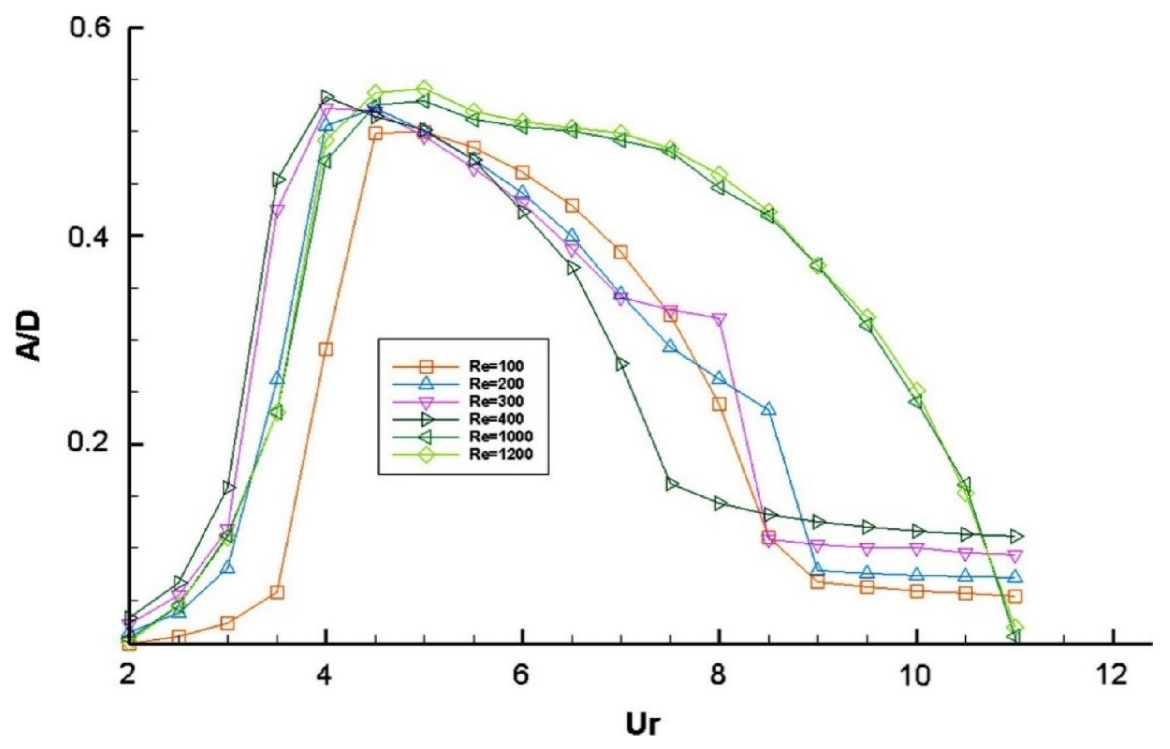
| Wanderley and Soares [90] | Numerical | Elastically supported | 100–1200 | 2–12 | A/D, f, CL |
| Chung [91] | Numerical | Elastically supported | 100 | - | A/D, CD, CL, FS |
| Raghavan and Bernitsas [92] | Experimental | Elastically supported | 2 × 10⁴−10 × 104 | 3–11 | A/D, f |
| Norberg [103,104] | Experimental | Fixed | <47 and 47–2.2 × 10⁷ | - | St, CL, CP |
| Kravchenko and Moin [105] | Numerical | Fixed | 3900 | - | St, CD, CP |
| Ma et al. [106] | Numerical | Fixed | 500–5000 | - | St, CD, CP |
| Park and Lee [107] | Experimental | Fixed | 20,000 | - | CP |
| Singh and Mittal [108] | Numerical | Elastically supported | 50–500 | 4.92 | A/D, St, CD, CL, FS |
| Kim and Choi [109] | Numerical | Fixed | <40 and 40–3900 | - | CD, CL, CP |
| Alam et al. [110] | Numerical | Forced | 300 | 2.77 | CL, CD, FS |
| Marquart et al. [111] | Numerical | Fixed | 1 × 10⁴, 1 × 10⁵ | - | CD, FS |
| Zhao et al. [112] | Numerical | Elastically supported | 150–1000 | 2–12 | A/D, f, CD, CL, FS |
| Kim et al. [113] | Experimental | Elastically supported | 1.4 × 10⁴–3.2 × 10⁴ | 0.4–22 | A/D, FS |
| Researchers | Methodology | Mounting | Re | Measurements |
|---|---|---|---|---|
| Abdelhamid et al. [5] | Numerical | Fixed | 40–180 | Nu, CD, CL, flow field |
| Alam et al. [32] | Numerical | Fixed | 150 | Nu, CD, CL, FS, flow field |
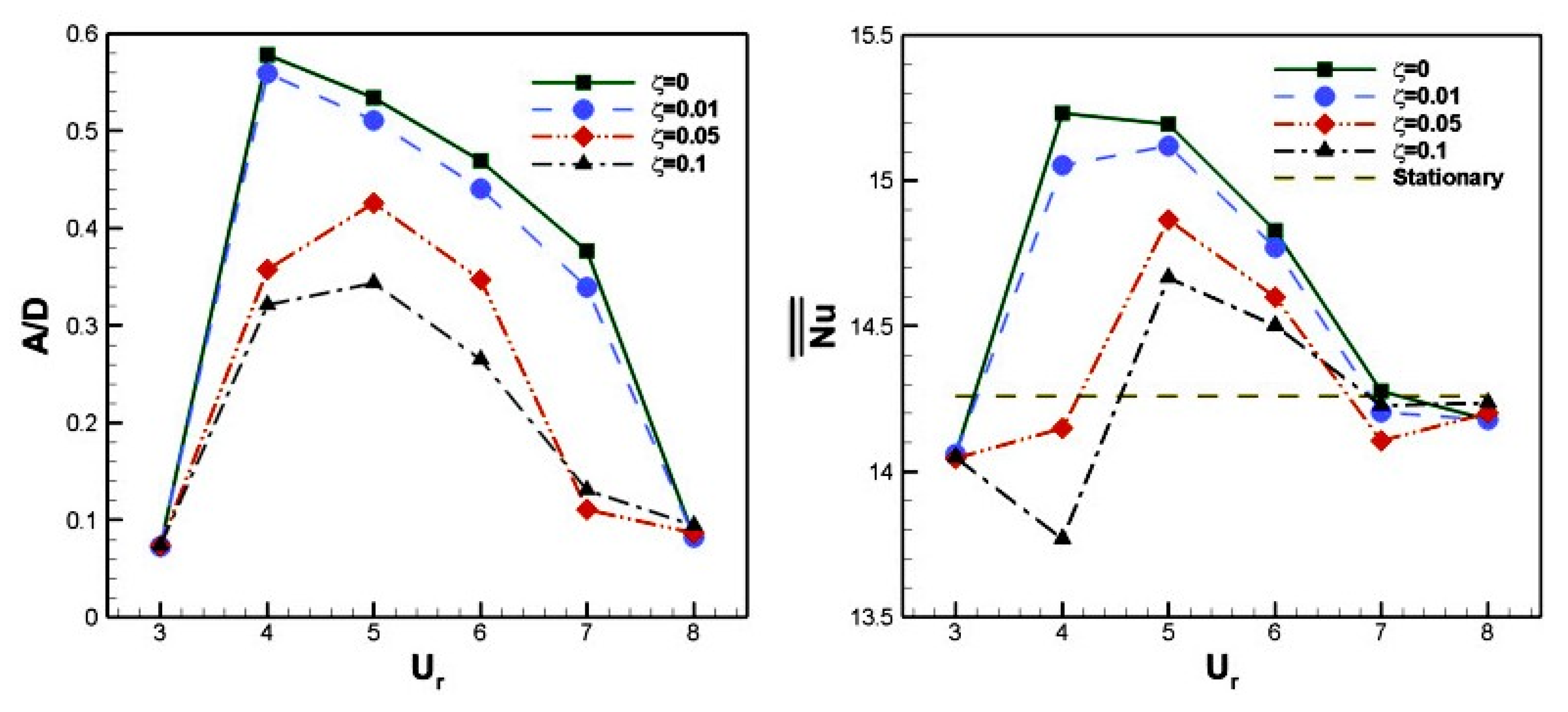
| Izadpanah et al. [56] | Numerical | Elastically supported | 150 | Nu, A/D, FS |
| Cheng et al. [114] | Experimental | Forced transverse vibration | 0–4000 | Nu, FS |
| Gau et al. [115] | Experimental | Forced transverse vibration | 1600–4800 | Nu, FS |
| Baratchi et al. [116] | Numerical | Elastically supported | 200 | Nu, CD, St, FS |
| Nakamura and Igarashi [122] | Experimental | Fixed | 3000–15,000 | Nu, FS |
| Kumar and Jayavel [131] | Numerical | Fixed | 50–1000 | Nu, CD, St, FS |
| Ali et al. [132] | Numerical | Forced streamwise vibration | 100 | CD, CL, St |
| Zafar and Alam [133] | Numerical | Fixed | 150 | Nu, CD, CL, FS, flow field |
| Ali et al. [134] | Numerical | Forced transverse vibration | 100 | CD, CL, St |
| Homsi et al. [135] | Numerical | Fixed | 80–200 | CD, CL, St, h |
| Researchers | Methodology | Mounting | Re | Cylinder Spacing | Measurements |
|---|---|---|---|---|---|
| Alam [37] | Experimental | Fixed | (1–6.5) × 104 | L* = 1.1–4.5 | CL, CD, St |
| Papaioannou et al. [61] | Numerical | Elastically supported | 160 | L* = 2.5, 3.5, 5 | A/D, CL, CD, FS |
| Zhao et al. [67] | Numerical | Elastically supported | 200 | L* = 1.5, 2, 3 | A/D, f, FS |
| Alam [73] | Numerical | Elastically supported | 150 | L* = 1.5, 3.0 | A/D, FS |
| Zhao et al. [112] | Numerical | Elastically supported | 4267 | L* = 1.2–2.8 | A/D, FS |
| Lin et al. [137] | Experimental | Fixed | 1 × 10⁴ | L* = 1.15–5.1 | VF |
| Zhou and Yiu [138] | Experimental | Fixed | 7000 | L* = 2 | VF |
| Kim et al. [142,143] | Experimental | Elastically supported | 4365−74,200 | L* = 0.1–3.2 | A/D, FS |
| Xu et al. [144] | Experimental | Elastically supported | 28,600–114,000 | L* = 1.57, 2.57, 3.57, 4.57 | A/D, f, CL |
| Sun et al. [145] | Experimental | Elastically supported | 30,000–120,000 | L* = 1.57, 2, 2.57 | A/D, f, FS |
| Huarte and Gonzalez [146] | Experimental | Elastically supported | 7000–28,000 | L* = 1.3 | A/D, f, CL, CD, FS |
| Alam et al. [148] | Experimental | Fixed | 6.5 × 10⁴ | L* = 1–8 | CL, CD, CP, St, FS |
| Assi et al. [149] | Experimental | Elastically supported | 3000–13,000 | L* = 2–5.6 | A/D, FS |
| Borazjani and Sotiropoulos [150] | Numerical | Elastically supported | 200 | L* = 3–14 | A/D, FS |
| Brika and Laneville [151] | Experimental | Elastically supported | 5000–27,000 | L* = 7–25 | A/D, FS |
| Gao et al. [152] | Experimental | Elastically supported | 7200 | L* = 0.5, 2, 3, 5 | Vorticity, FS |
| Kitagawa and Ohta [153] | Numerical | Fixed | 2.2 × 10⁴ | L* = 2–5 | CL, CD, CP, St, FS |
| Kondo and Matsukuma [154] | Numerical | Fixed | 1000 | L* = 2–5 | CL, CD, FS |
| Carmo et al. [155] | Numerical | Elastically supported | 100–645 | L* = 4 | A/D, CL, FS |
| Brika and Laneville [156] | Experimental | Elastically supported | 5100–27,500 | L* = 7–25 | A/D |
| Sumner et al. [157] | Experimental | Fixed | 1200–3000 | T* = 1–3 | St, VF |
| Sumner et al. [158] | Experimental | Fixed | 850, 1350 | P* = 1–5 α = 0–90° | St, VF |
| Zhou et al. [159] | Experimental | Fixed | 1800 | T* = 1.5–3 | VF |
| Farrant et al. [160] | Numerical | Fixed | 100, 200 | L* = 5, T* = 4 | CL, CD, St |
| Meneghini et al. [161] | Numerical | Fixed | 100–200 | L* = 1.5–4 | CL, CD, St |
| Ozono et al. [162] | Experimental | Fixed | 2500–7500, 3 × 10⁴ | L* = 1–4 T* = 0–2 | CP, St |
| Zhou et al. [163] | Experimental | Fixed | 5800 | T* = 1.5–3 | VF |
| Wang et al. [164] | Experimental | Fixed | 120–1.65 × 10³ | T* = 1.13, 1.7, 3 | Vorticity |
| Xu et al. [165] | Experimental | Fixed | 1000–1.4 × 10⁴ | T* = 1.2–1.6 | St, VF |
| Chen et al. [166] | Numerical | Fixed | 750 | T* = 2.7, 4 | CP, VF |
| Jester and Kallinderis [167] | Numerical | Fixed | 80, 1000 | L* = 0–10 T* = 0–4 | CL, CD, St |
| Kang [168] | Numerical | Fixed | 40–160 | T* = 1–6 | CL, CD, St |
| Alam et al. [169,170] | Experimental | Fixed | 5.5 × 10⁴ | T* = 1.1–6 | CL, CD, CP, St, FS |
| Akosile and Sumner [171] | Experimental | Fixed | 50,000 | P* = 1.125–1.25 α = 0–90° | CL, CD, CP, St |
| Sumner and Richards [172] | Experimental | Fixed | 3.2 × 10⁴ | P* = 2–2.5 α = 0–90° | CL, CD, St |
| Sumner [173] | Experimental | Fixed | 5 × 10⁴ | P* = 1.125–1.25 α = 0–90° | CL, CD, CP, St |
| Xu and Zhou [174] | Experimental | Fixed | 800 | L* = 1–15 | St |
| Mittal and Kumar [175] | Numerical | Elastically supported | 1000 | L* = 5.5 | A/D, CL, CD, FS |
| Brun et al. [176] | Experimental | Fixed | 1000–14,300 | T* = 1.583 | St, VF |
| Alam and Sakamoto [177] | Experimental | Fixed | 5.5 × 10⁴ | P* = 1.1–6 α = 10–75° | St |
| Alam et al. [178] | Experimental | Fixed | 350, 5.5 × 10⁴ | P* = 1.1–6 α = 10–75° | CL, CD, CP, FS |
| Sumner et al. [179] | Experimental | Fixed | 3.2 × 10⁴ | P* = 1.125–4 α = 0–90° | CL, CD, St |
| Sharman et al. [180] | Numerical | Fixed | 100 | L* = 2–10 | CL, CD, CP, St |
| Akbari and Price [181] | Numerical | Fixed | 800 | P* = 1.1–3.5 α = 0–70° | St |
| Agrawal et al. [182] | Numerical | Fixed | 73 | T* = 1.7, 3.5 | CL, CD, CP, VF |
| Sumner and Schenstead [183] | Experimental | Fixed | (3.2–7.4) × 104 | P* = 1.125–4 α = 0–9° | CL, CD, CP, St |
| Carmo and Meneghini [184] | Numerical | Fixed | 160–320 | L* = 1.2–8 | CL, CD, St |
| Deng et al. [185] | Numerical | Fixed | 220–270 | L* = 1.5–8 | CD, St, VF |
| Huang et al. [186] | Numerical | Fixed | 150 | L* = 1–1.9 | VF |
| Papaioannou et al. [187] | Numerical | Fixed | 100–1000 | L* = 1.1–5 | CL, CD, St |
| Kondo and Matsukuma [188] | Numerical | Fixed | 1000 | L* = 3–4 T* = 0–1.1 | CL, CD, CP |
| Liu et al. [189] | Numerical | Fixed | 40–100 | T* = 1.1–3 | CL, CD, St |
| Wang et al. [190] | Numerical | Fixed | 60–200 | L* = 1.7 | CL, CD, St |
| Alam and Zhou [191] | Experimental | Fixed | 4.7 × 10⁴ | T* = 1.1–1.2 | CL, CD |
| Alam and Zhou [192] | Experimental | Fixed | 5.5 × 10⁴–6.5 × 10⁴ | L* = 1.1–9 | CL, phase angle |
| Mizushima and Ino [193] | Numerical | Fixed | 20–80 | T* = 1.3–2 | St, FS |
| Hu and Zhou [194,195] | Experimental | Fixed | 300, 7000 | P* = 1.2–4 α = 0–90° | St, VF |
| Carmo et al. [196] | Numerical | Fixed | 200–350 | T* = 5–5.8 α = 0–31° | CD, St, VF |
| Lee et al. [197] | Numerical | Fixed | 100 | L* = 1–5 T* = 1–5 | CL, CD, CP, St |
| Zhou et al. [198] | Experimental | Fixed | 1500, 2×10⁴ | P* = 1.2–4 α = 0–90° | St |
| Kumar et al. [199] | Experimental | Fixed | 250, 350, 450 | T* = 1.1, 1.7, 3 | St, VF, vorticity |
| Singha and Sinhamahapatra [200] | Numerical | Fixed | 40-150 | L* = 1.2–5 | CL, CD, St |
| Assi et al. [201] | Experimental | Elastically supported | 0.25 × 10⁴−2.5 × 10⁴ | L* = 4, 5, 6, 8, 10, 20 | A/D, f, FS |
| Wang et al. [202] | Numerical | Fixed | 60, 80, 100 | L* = 1–12 | CL, CD, VF |
| Carmo et al. [203,204] | Numerical | Fixed | 160-320, 80–500 | L* = 1.2–10 | CL, CD |
| Dehkordi et al. [205] | Numerical | Fixed | 100, 200 | L* = 1.5–5.5 | CL, CD, St, VF |
| Vakil and Green [206] | Numerical | Fixed | 1-20 | L* = 1.1–31 | CL, CD |
| Sarvghad et al. [207] | Numerical | Fixed | 100, 200 | T* = 1.5–4 | CL, CD, CP, VF |
| Alam and Meyer [140,208] | Experimental | Fixed | 55,000 | P* = 1.1–6 α = 0–90° | CL, CD, CP, St, FS |
| Tsutsui [209] | Experimental | Fixed | 3.8×10⁴–1.3×10⁵ | L* = 1.2–1.3 | CL, CD, CP, FS |
| Koda and Lien [210] | Numerical | Fixed | 160–220 | L* = 1.5–8 | CL, CD, St |
| Wong et al. [211] | Experimental | Fixed | 1500–2 × 10⁴ | P* = 1.2–6 α = 0–90° | St |
| Jiang et al. [212] | Numerical | Fixed | 100 | L* = 2–8 | CL, CD, St, FS |
| Mysa et al. [213] | Numerical | Elastically supported | 100 | L* = 4–10 | A/D, f, CL, CP, FS |
| Homsi et al. [214] | Numerical | Fixed | 80–250 | L* = 2, 4, 8 | CD, VF, TF |
| Researchers | Methodology | Mounting | Re | Cylinder Spacing | Measurements |
|---|---|---|---|---|---|
| Kumar and Jayavel [131] | Numerical simulation | Fixed | 50–200 | blockage ratio: 1.54–5 | CL, CD, CP, St, Nu, h |
| Zhou and Yiu [138] | Experimental | Fixed | 7000 | L* = 1.3–6 | VF, TF |
| Zhou et al. [159] | Experimental | Fixed | 1800 | L* = 1.5–3 | VF, TF |
| Zhou et al. [163] | Experimental | Fixed | 5800 | T* = 1.5–3 | VF, TF |
| Mahir and Altac [215] | Numerical simulation | Fixed | 100, 200 | L* = 2, 3, 4, 5, 7, 10 | CL, CD, CP, St, Nu, vorticity, isotherms |
| Dhiman et al. [216] | Numerical simulation | Fixed | (2.1–3.5) × 104 | L* = 1.2–4 | CL, CD, CP, St, Nu, vorticity, pathlines |
| Harimi and Saghafian [217] | Numerical simulation | Fixed | 100, 200 | L* = 2, 3, 4, 5, 7, 10 | CL, CD, St, Nu, vorticity, isotherms |
| Kostic and Oka [218] | Experimental | Fixed | 1.3 × 10⁴–4 × 10⁴ | L* = 1.6–9 | CL, CD, CP, Nu |
| Sisodia [219] | Numerical simulation | Fixed | 10–45 | L* = 3α = 0–180° | CL, CD, St, Nu, vorticity |
| Zafar and Alam [220] | Numerical | fixed | 200 | L* = 6 | CL, CD, St, Nu, vorticity |
| Zhang et al. [221] | Numerical simulation | Fixed | 100 | G = 1–8 | FS, TF, vorticity |
| Researchers | Methodology | Number of Cylinders | Cylinders Arrangement | Re | Geometric Parameters | Ur |
|---|---|---|---|---|---|---|
| Yang et al. [11] | Numerical | 1 | - | 100 | m* = 1.38 ζ = 0 | 3–10 |
| Tu et al. [58] | Numerical | 2 | Tandem | 120 | L* = 10 m* = 6 ζ = 0 | 3–26 |
| Chen et al. [59] | Numerical | 2 | Side-by-side | 100 | T*=2.0–5.0, m* = 2 ζ = 0 | 0–10 |
| Papaioannou et al. [61] | Numerical | 2 | Tandem | 160 | L* = 2.5, 3.5, 5 | 3–10 |
| Han et al. [62] | Numerical | 4 | Square arrangement | 80, 160 | L* = 5 m* = 6 | 3–14 |
| Chung [63] | Numerical | 2 | Side-by-side, tandem, and staggered | 100 | L* = 1.1, 1.3, 1.5, 1.7, 1.9 α = 0°, 30°, 60°, 90° m*=2 ζ = 0 | 2–16 |
| Wang et al. [64] | Numerical | 3 | Equilateral-triangle arrangement | 150 | L* = 4 α = 0°, 30°, 60° m* =2 ζ = 0 | 3–12 |
| Wang et al. [65] | Numerical | 2 | Tandem | 50–200 | L* = 5.5 | 3–30 |
| Assi [228] | Experimental (Water channel) | 2 | Tandem and staggered | 2000–25,000 | L* = 4 T* = 0–3 m* = 1.6 ζ = 0.003 | 1–11 |
| Prasanth et al. [229,230] | Numerical | 2 | Tandem and staggered | 100 | L* = 5.5 T* = 0 and 0.7 m* = 10 ζ = 0 | 2–15 |
| Researchers | Methodology | Number of Cylinders | Re | Geometric Parameters | Ur | Surface Roughness Ks/D | Measurements |
|---|---|---|---|---|---|---|---|
| Gao et al. [75] | Numerical | 1 | 5000 | m* = 2.6 ζ = 0.0036 Gap from wall (e/D) = 2 | 1–14 | 0, 0.005, 0.01, 0.02 | St, A/D, fex, FS, vorticity |
| Sun et al. [145] | Experimental | 2 (Tandem) | 30,000–120,000 | L* = 1.57, 2, 2.57 m*=1.34 k = 400, 1200 ζ = 0.02–0.26 | 2.92–15.33 | 0.0095 | A/D, fex, vorticity |
| Zhou et al. [238] | Experimental | 1 | 6000–80,000 | - | Fixed cylinder | 0.0028–0.025 | CD, CL |
| Gao et al. [240] | Numerical | 1 | 5000 | m* = 2.6 ζ = 0.0036 Gap from wall (e/D) = 0.8, 2 | 1–14 | 0.01, 0.02 | St, A/D, fex, CD, CL, FS, vorticity |
| Dierich and Nikrityuk [241] | Numerical | 1 | 10–200 | - | Fixed cylinder | 0.01–0.5 | CD, Nu |
| Skeide et al. [242] | Experimental | 1 | 20,000–160, 000 | - | Fixed cylinder | 0.1, 0.2, 0.42 | CD, vorticity |
| Han et al. [243] | Numerical | 1 | 1500–10,500 | m* = 2.6 ζ = 0.0036 | 2–14 | 0.005, 0.01, 0.02 | A/D, vorticity |
Publisher’s Note: MDPI stays neutral with regard to jurisdictional claims in published maps and institutional affiliations. |
© 2021 by the authors. Licensee MDPI, Basel, Switzerland. This article is an open access article distributed under the terms and conditions of the Creative Commons Attribution (CC BY) license (https://creativecommons.org/licenses/by/4.0/).
Share and Cite
Ali, U.; Islam, M.; Janajreh, I.; Fatt, Y.; Alam, M.M. Flow-Induced Vibrations of Single and Multiple Heated Circular Cylinders: A Review. Energies 2021, 14, 8496. https://doi.org/10.3390/en14248496
Ali U, Islam M, Janajreh I, Fatt Y, Alam MM. Flow-Induced Vibrations of Single and Multiple Heated Circular Cylinders: A Review. Energies. 2021; 14(24):8496. https://doi.org/10.3390/en14248496
Chicago/Turabian StyleAli, Ussama, Md. Islam, Isam Janajreh, Yap Fatt, and Md. Mahbub Alam. 2021. "Flow-Induced Vibrations of Single and Multiple Heated Circular Cylinders: A Review" Energies 14, no. 24: 8496. https://doi.org/10.3390/en14248496
APA StyleAli, U., Islam, M., Janajreh, I., Fatt, Y., & Alam, M. M. (2021). Flow-Induced Vibrations of Single and Multiple Heated Circular Cylinders: A Review. Energies, 14(24), 8496. https://doi.org/10.3390/en14248496