Article

Modernization of the Mechanical Fuel System of a Diesel Locomotive Engine through Physical and Numerical Modeling †

by
Leonid Plotnikov
1,* and
Nikita Grigoriev
1,2
1
Turbines and Engines Department, Ural Federal University Named after the First President of Russia B. N. Yeltsin, Str. Mira 19, 620002 Yekaterinburg, Russia
2
Ural Diesel-Motor Plant LLC, Str. Front Brigades 18, 620017 Yekaterinburg, Russia
*
Author to whom correspondence should be addressed.
This paper is an extended version of our paper published International Conference on Efficient Production and Processing, Kazan, Russia, 26 February 2021; pp. 56–63.
Energies 2021, 14(24), 8554; https://doi.org/10.3390/en14248554
Submission received: 17 November 2021 / Revised: 9 December 2021 / Accepted: 16 December 2021 / Published: 18 December 2021

Abstract

:
Reducing harmful emissions from exhaust gases and increasing energy efficiency are urgent tasks when designing reciprocating internal combustion engines. In this experimental work, the fuel system of a diesel locomotive engine operating on the Miller cycle is improved. The purpose of the study is to improve the environmental and economic indicators of diesel engines at minimal financial cost. The article provides an overview of the main research on improving fuel supply, mixing and combustion. The features of engine operation are also briefly described. Numerical simulation of the diesel engine operating cycle was performed before the bench tests. The experiments were performed on a full-size diesel engine with a power of 1200 kW. The measuring equipment and experimental technique are described in the article. The technical solutions that made it possible to improve the fuel supply are described. A new design for the high-pressure fuel pump drive is proposed. The optimal fuel injection advance angles are determined. An original design for the fuel pump plunger was developed. The proposed technical solutions made it possible to reduce fuel consumption by up to 3% (from 217.8 to 211.4 g/kW·h) and NOx emissions two-fold (from 19.4 to 8.8 g/kW·h).

1. Introduction

Internal combustion engines (ICEs) powered by fossil fuels generate about 25% of the world’s energy and about 10% of the greenhouse gas emissions [1]. Reducing fuel consumption and emissions has been a major challenge for researchers and engine manufacturers. The potential to improve the efficiency and environmental friendliness of ICEs has not been fully exhausted [1,2,3].
A large number of ways to improve the environmental performance of piston ICEs and reduce fuel consumption have been pointed out in the literature. For our purposes, the most relevant are (1) optimizing the fuel system’s parameters (fuel supply method, injection pressure, fuel injection advance angle, etc.) [4,5,6]; (2) fine-tuning the design of the fuel injector and adjusting the time needed for fuel injection [7,8]; and (3) controlling the law of fuel supply during fuel supply [9]. Agarwal A. K. et al. [4] examined the effect of different injection strategies (different initial pressures and the start of the fuel supply) on the efficiency and environmental parameters of a diesel engine. As a result, a noticeable reduction in the emission of hydrocarbons and carbon dioxide was achieved with a slight decrease in specific fuel consumption. Through mathematical modeling, Sener R. and Gul M. Z. [6] studied the mutual influence of the shape of the combustion chamber and the parameters of fuel injection on the amount of harmful emissions. A total of 104 different combustion chamber shapes and 23 injection configurations were investigated. It was found that the use of the best combustion chamber design and optimal fuel injection parameters leads to a significant reduction in NOx and soot emissions. Kim H. J. et al. [7] investigated the influence of the fuel spray angles and the start of the fuel supply on the combustion efficiency and the amount of harmful substances in the exhaust gases. The influence of these parameters on the performance of a diesel engine is shown. Mohiuddin K. et al. [8] experimentally evaluated the effect of the number of holes in the nozzle and the injection time on the environmental performance of a diesel ICE. It should be noted that some data were obtained using optical research methods. Xu L. et al. [9] studied the influence of injection pressure and the law of fuel supply on the environmental and economic performance of a diesel engine with a common fuel system. As a result, these researchers developed a mathematical model that was able to predict the change in the degree of fuel atomization, pressure in the cylinder, the rate of heat release and the amount of emissions quite well. Many studies on improving the mixture formation and combustion have been performed using optical methods [8,10,11,12]. Optical research methods have made it possible to visualize the fuel supply process while qualitatively and quantitatively assessing the influence of the fuel system parameters on the ICE’s technical and economic indicators. Macian V. et al. [10] investigated the influence of nozzle design and the law of fuel supply on the environmental and economic performance of a diesel engine with optical methods; it was shown that these parameters have a significant effect on mixture formation and fuel combustion. Choi M. et al. [12] proposed an original method for estimating flame temperature, particulate matter and NOx emissions in a diesel engine. A comparison was made between the data obtained using the new method and those obtained using traditional research methods. Good convergence of the results was obtained and recommendations for using the technique were presented.
Another way forward is the improvement of fuel systems when the engine is operating in atypical conditions (low load, transient conditions, low temperatures, etc.) [13,14,15]. Agarwal A. K. et al. [13] studied low-temperature combustion at different fuel-system settings in order to improve the environmental performance of a vehicle diesel engine. As a result, experts formulated key recommendations for reducing emissions for combustion at low temperatures. It was shown in [14,15] that careful tuning of the fuel system can lead to an increase in efficiency up to 19% and a decrease in hydrocarbon emissions up to 60% and carbon monoxide up to 64% when the diesel engine operates at low loads. Moreover, the level of gas-dynamic noise [16,17] and the strength of parts in the combustion chamber depend on perfecting the fuel supply process [18,19]. This once again underlines the importance of a detailed study on mixture formation and combustion in diesel ICEs of various sizes and purposes. Finally, it is possible to highlight adjustments to the fuel supply process when adding certain impurities to diesel fuel. The additives can be hydrogen [20], ethanol [21], natural gas or methane [22,23], biofuels [24], gasoline [25] and water (humidification or steam supply) [26,27]. The recirculation of exhaust gases in the engine can also be considered as a type of additive in the components of the fuel–air mixture [28,29]. The addition of one or another component disrupts the traditional combustion process. Therefore, each additive requires unique settings for the fuel system so that combustion can take place efficiently and emit the minimum amount of harmful substances.
This article presents the results of modeling and bench tests performed to fine-tune the diesel fuel supply process. This article is an extended version of the conference paper we published earlier [30]. The main objective of the study is to improve the technical, economic and environmental performance of the diesel engine in question. The influence of the Miller cycle on the operational and environmental performance of this diesel engine is discussed in [31,32].

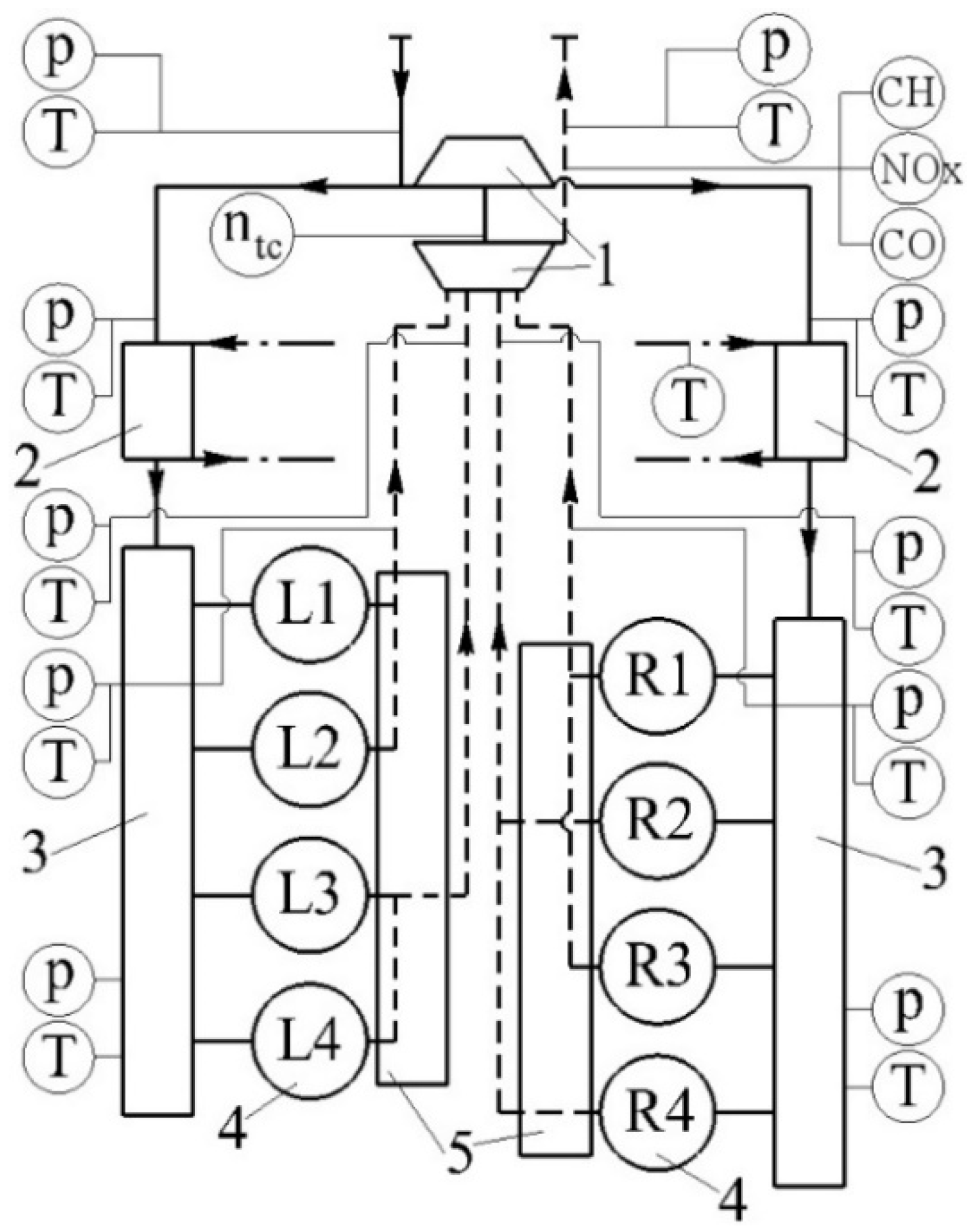
2. Research Object and Problem Statement

The object of this study is a diesel engine with the aforementioned dimensions (produced by Ural Diesel-Motor Plant, Yekaterinburg). The diesel engine was a 4-stroke engine with a V-shaped cylinder arrangement (8 pieces) at an angle of 90°, with direct fuel injection, a closed-type liquid cooling system, gas turbine supercharging, intercooling of the supercharged air and a lubrication system with a “dry” crankcase. The power of the engine was 1200 kW at a crankshaft speed of 1400 rpm and a maximum torque of 6000 N·m. The engine had a cylinder diameter of 210 mm and a piston stroke of 210 mm (i.e., 21/21): it operated on the Miller cycle. This engine has a conventional mechanical fuel system with a high-pressure block fuel pump. This system was chosen for several reasons: (1) diesel is used in remote, inaccessible regions of Russia; (2) diesel uses poor-quality fuel; and (3) the qualifications of the operator and maintenance personnel are low. Therefore, the main criteria for modernizing this diesel engine are the use of simple and inexpensive technical solutions that give the maximum effect. The specifications (main technical parameters) of the base engine are presented in Table 1. The general view of the diesel engine is shown in Figure 1.
As a result of previous studies, it was found that losses associated with a decrease in the opening time of the intake valves and a slight deterioration in the quality of gas exchange in the cylinders can be partially compensated by an increase in the boost pressure (by selecting the optimal flow paths of the turbochargers) and adjusting the fuel injection advance angle [30,31]. Accordingly, the main goal of these studies was to synchronize the fuel supply with the valve timing of a 21/21 diesel engine. In addition, the presented results were obtained for the nominal operating mode, although idle speed should be considered as an equally important operating mode. This is based on the fact that, according to statistics, diesel locomotives involved in shunting can spend up to 90% of their time idling [33].
Since the introduction of the Miller cycle had a negative impact on the indicators that determine the quality of mixture formation in diesel cylinders, a widely used method for restoring them is to increase the fuel injection pressure (the first stage of optimization). Additionally, the search for the optimal algorithm for changing the fuel injection advance angle φinj before the piston reaches the top dead center (TDC) during compression was performed in different operating modes (the second stage of optimization).
The technical, economic and environmental parameters of the engine under consideration were measured during the bench tests (Table 2). The measurement accuracy was ensured by the technical characteristics of the equipment and periodic verification. All measuring instruments were periodically verified before use.
An engine diagram and the sensor locations are shown in Figure 2. An automated system for collecting and processing experimental data was used in the tests. The performance of all sensors was optimal for all investigated modes of the diesel engine. Most of the data were auxiliary (indirect) for determining the key indicators of a diesel engine, which were discussed in the article. The graphic design of the picture was done using SolidWorks software. Engine tests were performed at different speeds and with different external loads, simulating the operation of a locomotive. The summarized test results are discussed later in this article.
Modeling of the operating cycle of a diesel locomotive engine was performed in the Diesel-RK program before experimental work. It should be noted that the numerical simulation of the cycle is an effective way to predict the efficiency and environmental friendliness of piston engines [34,35,36]. Today there are a large number of specialized software products for accurate calculation of the indicators and characteristics of engines. The most famous software are AVL Boost, GT-Power and others. These programs can pre-determine certain characteristics of the engine before performing experimental studies. The Diesel-RK program was developed by specialists from the Moscow State Technical University (Moscow, Russia). This program has a modern interface and fairly accurate mathematical models for calculating the working cycle of piston engines for various purposes. The basic equations for the Diesel-RK program are described in the articles of the developers, for example, [37,38]. Within the framework of this study, at first, the mathematical model was tuned for about 30 parameters of the diesel engine. Differences in the simulation results and data from the operation manual for this diesel engine did not exceed 5%. Further, numerical experiments were performed to assess the parameters of the fuel system for the operational characteristics of the investigated ICE.

3. Mathematical Modeling Results

Before conducting experimental studies, numerical modeling of the operating cycle of a locomotive engine was performed for a preliminary assessment of the influence of the parameters of the fuel system on the main indicators of the ICE. Two modes of engine operation were chosen for the simulation, namely, nominal mode and idle mode. These are the two main modes in which the locomotive operates most of the time. The indicators of the perfection of the working cycle were the minimum specific fuel consumption and the optimal amount of harmful substances in the exhaust gases. Numerical research was performed in three stages. At the first stage, the assessment of the influence of the number of holes in the nozzle sprayer on the technical, economic and environmental performance of the diesel engine was performed (Figure 3 and Figure 4).
Figure 3 shows that the number of holes in the injector nozzle has practically no effect on the engine power (both nominal and idle). At the same time, the specific fuel consumption increases with an increase in the number of holes in the nominal mode. In turn, the opposite tendency is observed in idle mode: the more holes, the lower the fuel consumption. It is noteworthy that the intersection of the fuel consumption lines at the nominal mode and the idle mode is observed when the number of holes is 8. Accordingly, it can be considered that 8 holes of the nozzle atomizer are optimal for this diesel engine from the point of view of efficiency of operation.
Figure 4 shows that the number of holes in the nozzle atomizer has a significant effect on the environmental friendliness and smoke of the exhaust gases of this ICE. Differences in the values of NOx emissions reach 20%, and the value of smoke changes almost 2 times. Similar results can be found in [4,7,39]. It was found that the amount of NOx emissions decreases with an increase in the number of holes. On the contrary, the smokiness of the combustion products increases with the number of atomizer holes. Accordingly, it can be stated that the optimal number of holes is 7 or 8 from the point of view of the environmental friendliness of a diesel locomotive.
Thus, at the first stage of the numerical simulation of the working cycle, it was found that the optimal number of holes in the nozzle atomizer is 8. This number of holes is taken for the second stage of the numerical study.
At the second stage, the assessment of the influence of the diameter of the holes in the nozzle atomizer on the technical, economic and environmental performance of the diesel engine was performed (Figure 5 and Figure 6).
Figure 5 shows that the diameter of the holes has almost no effect on the power of the ICE in the nominal mode and in the idle mode. Changes in power values are in the range of 1–2%. At the same time, the diameter of the holes has a significant effect on the specific fuel consumption. It was revealed that the specific fuel consumption also increases with an increase in the diameter of the holes in the nominal mode. Similar data were obtained in [7,11,40]. The opposite tendency took place in the idle mode: the specific fuel consumption decreased with an increase in the diameter of the holes. In this case, there is also an optimal diameter of the holes in the injector nozzle, which is 0.35 mm (this is the point of intersection of the functions of specific fuel consumption in the nominal and idle modes).
Figure 6 shows that the impact of the hole diameter on environmental performance is significant. The values of NOx emissions and exhaust gas smoke differ by tens of percent when the hole diameter changes from 0.25 to 0.4 mm. In particular, it was found that NOx emissions decreased with increasing hole diameters. The same data for another engine can be found in [7,18,41]. The effect of the hole diameter on the smoke of the exhaust gases does not have a pronounced tendency (there is a complex regularity characteristic of this type of engine). Accordingly, the optimal value of the diameter of the nozzle hole is 0.3–0.35 mm from the point of view of the environmental friendliness of the diesel engine.
Thus, at the second stage of the numerical simulation of the working cycle, it was found that the optimal value of the diameter of the holes in the nozzle atomizer is 0.35. This hole diameter was taken for the third stage of the numerical study.
At the final, third stage, the assessment of the influence of the fuel injection advance angle on the technical, economic and environmental performance of the piston engine was performed (Figure 7 and Figure 8).
Figure 7 shows that the fuel injection advance angle has an insignificant effect on the engine power (within 5%) in the nominal and idle modes. It should be noted that the power of the diesel engine decreases by an unacceptable value at large values of the angle φinj. The influence of the angle φinj on the specific fuel consumption is more pronounced. For example, there is a minimum of the function ge = finj) at angles equal to 25–29° at the nominal operating mode of the diesel engine. At the same time, the minimum specific fuel consumption takes place at angles φinj = 18–23° at idle. Accordingly, it can be stated that the optimal value of the fuel injection advance angle depends on the operating mode of the piston ICE.
Figure 8 shows that the influence of the fuel injection advance angle on the environmental performance of a diesel engine is significant in the nominal and idle modes. It was found that there is a 2–3-fold decrease in NOx emissions with an increase in the angle φinj. This is typical for both operating modes of the piston ICE. On the contrary, there is a tenfold increase in the smoke content of the exhaust gases with an increase in φinj. Accordingly, the optimal values of the fuel injection advance angle are in the range of 25–34 degrees.
It is known that the simulation results need to be verified, refined and compared with experimental studies. The data from the mathematical modeling made it possible to determine the initial parameters of the fuel system of a diesel engine for experimental research. This made it possible to significantly reduce the time and cost of debugging a diesel engine.

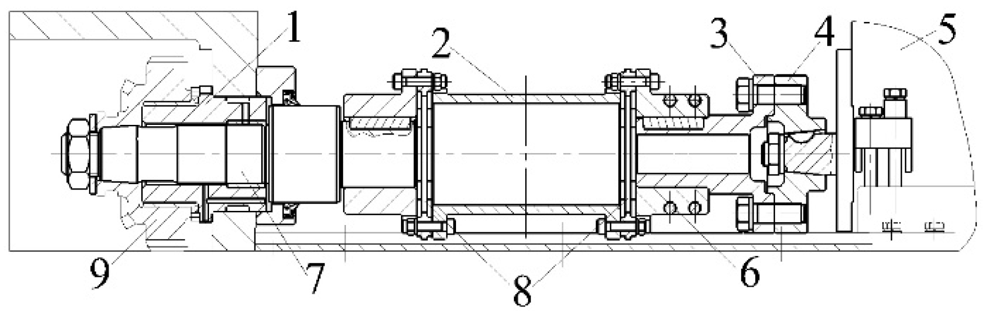
4. Modernizing the High-Pressure Fuel Pump and Its Drive

Experimental studies were performed in two stages. The implementation of the first stage of optimization was performed by installing a high-pressure fuel pump (HPFP), which provides fuel pressure at the outlet from the injection nozzles at a level of 100 MPa in the nominal operating mode. This parameter was about 70 MPa for the base injection pump. The limitation in increasing the injection pressure (up to 100 MPa) lies in the design of the high-pressure fuel pump. It is impossible to increase the injection pressure by a large amount without replacing the pump due to the mechanical and hydraulic limitations of the existing fuel system.
There are permanent problems of the fineness of fuel atomization in the combustion chamber and control of the structure (shape) of the fuel jet to achieve effective mixture formation and subsequent combustion in the field of piston engine building [42,43]. The theory of turbulent combustion was first formulated by Damkohler in 1940 [44]. He proposed to consider two types of turbulent combustion: small-scale and large-scale. Until now, the main provisions of this theory are used in mathematical models to describe the combustion of fuel and to choose the direction of improving the processes of mixture formation and combustion in diesel engines. Today, it is known that reducing the size of droplets and controlling the shape of the jet has a positive effect on engine power, fuel consumption, toxicity of exhaust gases and the reliability of its main parts and assemblies [39,45]. This study confirmed previously known facts about the influence of injection pressure on engine fuel consumption. Increasing the pressure causes the droplet size to decrease. This led to an increase in power (up to 5%) and a decrease in specific fuel consumption within 2.5% for the investigated diesel engine.
Only the design of the plunger pairs underwent changes (the diameter of the plunger and the geometry of the cut-off edge have been increased). The block design of the HPFP, the pump shaft drive and other technical features remained unchanged. During this stage, alternative injector nozzle configurations were selected in order to maintain an equivalent volume of supplied fuel as injection pressure increased and to ensure an optimal fuel flame. These configurations are based on analytical calculations and a simulation of the diesel engine’s operating cycle. Table 3 shows the results of the comparative tests of a base diesel engine (option No. 1), a diesel engine with a Miller cycle and a basic fuel system (option No. 2) and a diesel engine with a Miller cycle and an upgraded fuel system (option No. 3). As a result, the nozzle atomizer configuration with the most stable spray performance in various operating modes was determined, this being a 9 × 0.31 × 153° nozzle with an 8 × 0.4 × 145° base atomizer. It should be noted that the design and adjustments of the nozzle remained unchanged (in particular, the pressure at the beginning of the lift of the nozzle needle (the start of the injection) is 26+1 MPa).
Thus, the best results in terms of specific effective fuel consumption come from option No. 2. This indicates the basic fuel system has a sufficient degree of consistency with the working process of a modernized diesel engine. In this case, specific fuel consumption decreased by 2.5%, the NOx emission decreased by 27% and the smoke level increased almost two-fold in comparison with the base engine. As expected, option No. 3 (using a HPFP with increased fuel injection pressure) did not have a positive effect: there was a decrease in fuel consumption within 1%, a two-fold decrease in NOx emissions and an almost 4-fold increase in smoke.
Measurements of the instantaneous camshaft rotation frequency (speed) of the HPFP, as well as measurements of the phase mark (deflection angle) by the rotation angle of the pump, were performed to find the reasons for the abnormal deterioration of engine performance as injection pressure (and, accordingly, the fineness of the fuel atomization) increases (Figure 9). The data were obtained in the nominal operating mode (the camshaft rotation frequency of the HPFP was 700 rpm). The speed of the injection pump camshaft was revealed to be highly uneven. Oscillations of the shaft cam relative to its rotation angle were also detected. The maximum cam oscillation amplitude was about 9°. The results of studies by other authors show that this has a significant effect on mixture formation and combustion [2,24].
Analysis of the graphs in Figure 3 indicates that there is a certain “lag” in the position of the cam of the injection pump shaft relative to the diesel camshaft at the start of fuel injection. Accordingly, the start of fuel injection moves closer to TDC. Moreover, there are additional fluctuations in the speed of the HPFP’s camshaft (uneven speed). It is suggested that these processes are the reasons for the discrepancy between the actual and predicted quality of fuel atomization in the combustion chamber, which leads to an increase in fuel consumption and smoke.
It is most likely that the source of these negative phenomena is the “shifting” of the components of the injection pump drive. The component in question is the spline spring that meshes with the diesel camshaft through intermediate gears (Figure 10). In order to eliminate this problem, it was decided to revise the design of the HPFP drive in order to increase rigidity. The spline spring was replaced with a coupling structure with rigid conical landings, while elastic elements were used to compensate for torsional vibrations (Figure 11).
The use of the modernized HPFP drive had a positive effect on fuel efficiency and environmental performance (Table 4).
The improvement of the ICE’s main indicators applies to all the investigated options. The greatest positive effect was obtained with the simultaneous use of a new drive and increased fuel injection pressure (option No. 3 in Table 3). In this case, specific fuel consumption was 2.7% less than for the basic configuration of a diesel engine, NOx emissions decreased two-fold and the smoke content of the exhaust gases increased by 33%. The obtained effect is satisfactory; however, it was decided to seek further improvement by amending the injection time.

5. The Fuel Injection Advance Angle and the Pump Plunger

In the second stage of optimization, tests were performed at various fuel injection advance angles φinj. The angles ranged from 12° to 40° to TDC in 2° steps. In the unmodified diesel engine, the fuel injection advance angle φinj is 33–35° to TDC and does not change in different operating modes. The tests were performed in accordance with the operating regime of a shunting locomotive. This article presents the test results for the two most typical engine operating modes for a shunting diesel locomotive, namely, (1) position No. 1 of the diesel locomotive controller (crankshaft speed n = 520 rpm, power 155 kW–idle) and (2) the rated load (n = 1400 rpm and power 1200 kW). The results are shown in Figure 12 and Figure 13. These data correspond to the configuration of the diesel engine for option No. 3 (see Table 3). Specific effective fuel consumption (ge) and NOx emission in exhaust gases were chosen as the target indicators of the engine’s efficiency, provided that the power is maintained. It is established that the lowest specific effective fuel consumption ge is 252.1 g/(kW·h)·at n = 520 rpm and is obtained at a fuel injection advance angle φinj of 24° to TDC. In the nominal operating mode, parameter ge is 211.4 g/(kW·h), which is obtained at φinj of 34° to TDC.
It should also be noted that some stabilization of fuel consumption is observed over a range of 211.4–214.3 g/(kW·h) for angles φinj ranging from 32° to 40° in the nominal mode. There is a gradual increase in NOx emission as the fuel injection advance angle increases in all operating modes. Similar results were obtained by other authors [23,42]. NOx emissions are within the permissible values according to ISO-8178 for angles φinj ranging from 24° to 34°.
Thus, the optimal angle φinj is within 24°–34° to TDC and tends to increase as load increases. Since the dependence of the optimal φinj on load is not linear, to implement the algorithm for changing the angle during diesel operation, it will be necessary to introduce technical devices such as a freewheel, servo drive, etc., which will further complicate the pump drive. This problem is also easily solved by using a storage fuel system with electronic control of fuel injection. For the reasons described above, it was decided to abandon the implementation of complex technical solutions.
An alternative technical solution for implementing the nonlinear law of fuel supply is structural modifications to the nozzle plunger’s cut-off edge (Figure 14).
The new plunger made it possible to change the fuel supply law hydraulically. In this case, the displacement at the start of the injection process towards TDC occurs at low volumes of cycle feed. The optimal angle φinj of 34° is maintained at the nominal cycle’s fuel supply. This method is not technically difficult. The modernization of the plunger does not incur significant financial costs. This optimization of the fuel system makes it possible to significantly reduce fuel consumption and the emission of harmful substances in the diesel engine under consideration.

6. Conclusions

The following conclusions can be formulated on the basis of various studies on the operating cycle of a diesel engine (21/21):
(1)
Increasing the fuel injection pressure is an effective method for compensating for Miller losses and reducing smoke.
(2)
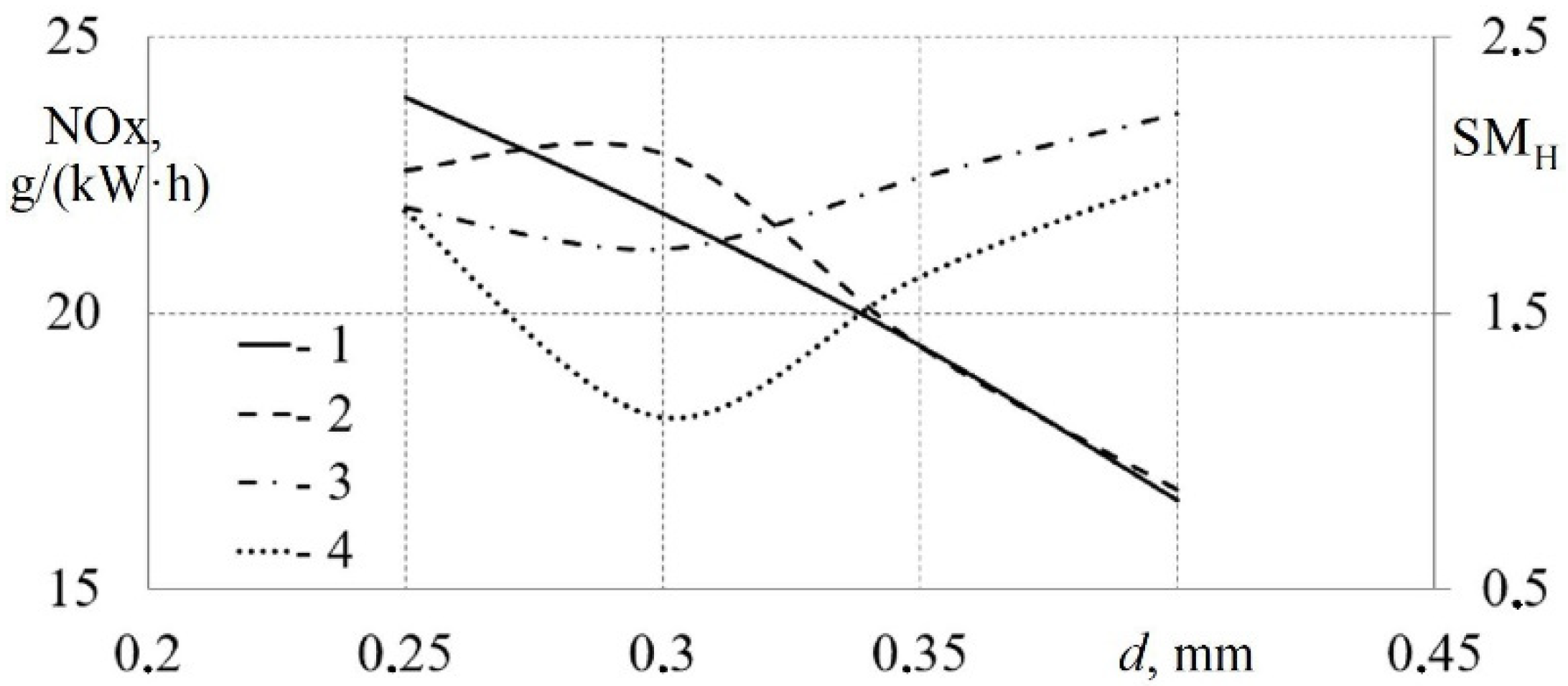
A mathematical model of the operating cycle of a diesel locomotive engine was created in the Diesel-RK program; the influence of the geometric parameters of the nozzle atomizer (number of holes and diameter) on the technical, economic and environmental performance of the diesel engine was shown; and on the basis of a numerical experiment, the influence of the fuel injection advance angle on the characteristics of a diesel engine was evaluated; thus, the configurations of spray nozzles for experimental studies of an ICE (21/21) were determined.
(3)
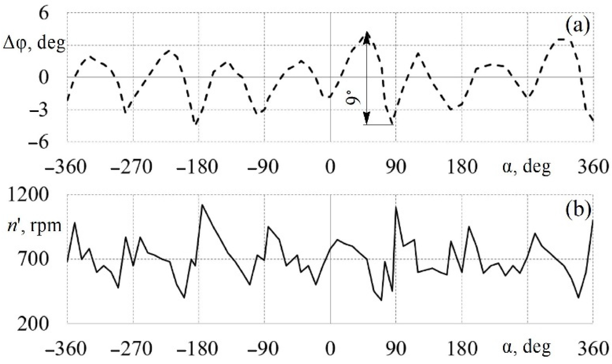
An increase in fuel injection pressure from 70 MPa to 100 MPa by using a HPFP with modernized plunger pairs and a basic design of the pump drive has a negative effect on the efficiency of the fuel system and diesel engine due to the appearance of additional vibrations in the shaft line.
(4)
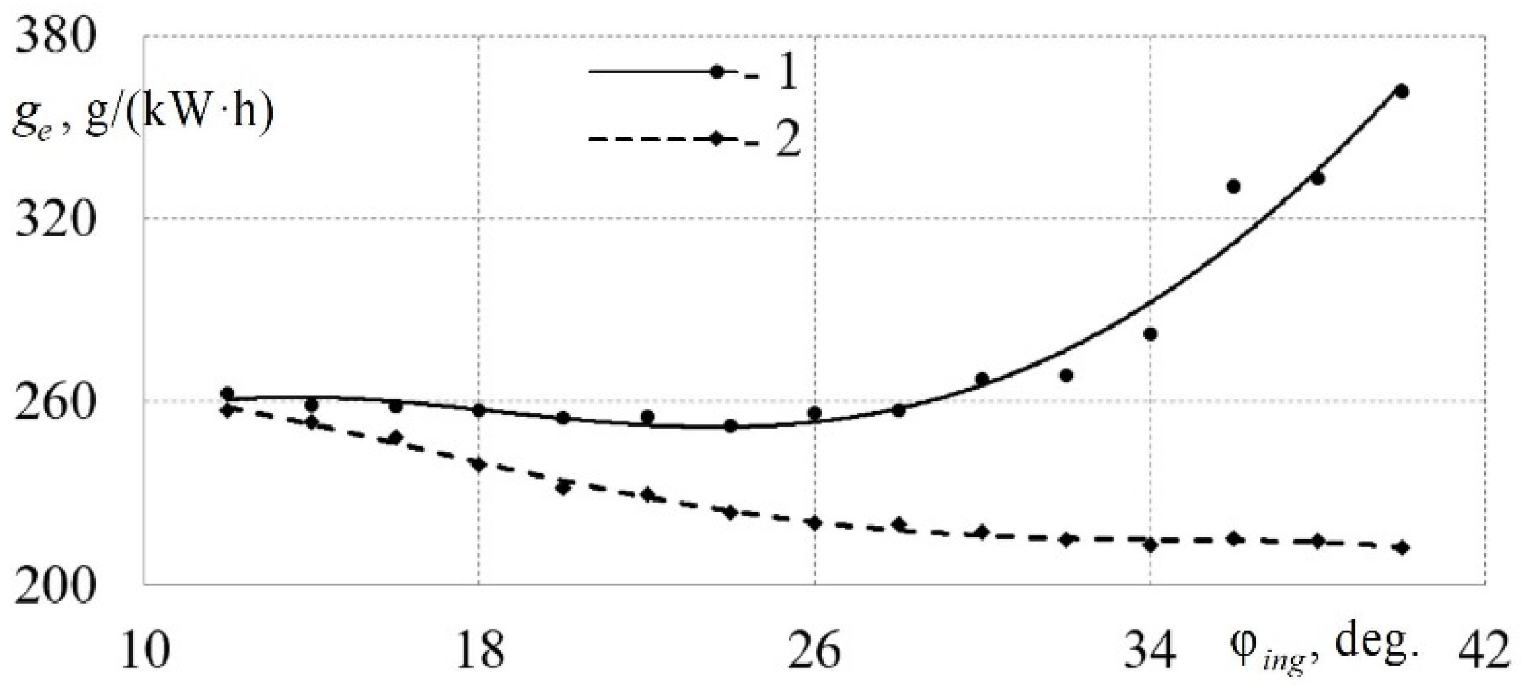
The lowest rate of specific effective fuel consumption (211.4 g/(kW·h)) is achieved when the fuel injection advance angle ranges from 24° to 34° to TDC.
(5)
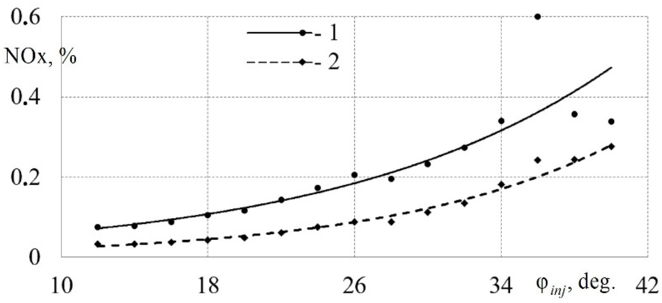
An increase in the fuel injection advance angle causes a gradual increase in NOx emissions, regardless of the diesel engine operating mode.
(6)
NOx emissions are within acceptable limits (according to ISO-8178 requirements) for fuel injection advance angles ranging from 24° to 34° to TDC for all of the diesel engine’s operating modes.
(7)
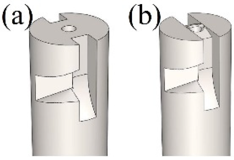
One effective method for obtaining a nonlinear algorithm to change the fuel injection advance angle is to correct the shape of the HPFP plunger’s cut-off edge.
(8)
The modernization of the fuel system makes it possible to reduce specific fuel consumption by almost 3% and NOx emissions by almost 30% in comparison with a basic ICE.
This research could be developed further by modernizing the boost system of this engine in order to increase the specific indicators. It is also planned to introduce an exhaust gas recirculation system and electronically controlled injectors.

Author Contributions

Conceptualization, L.P. and N.G.; methodology, L.P. and N.G.; software, L.P.; validation, L.P. and N.G.; formal analysis, N.G.; investigation, L.P. and N.G.; resources, N.G.; data curation, L.P. and N.G.; writing—original draft preparation, L.P.; writing—review and editing, L.P.; visualization, N.G.; supervision, L.P.; project administration, L.P. All authors have read and agreed to the published version of the manuscript.

Funding

This research received no external funding.

Institutional Review Board Statement

Not applicable.

Informed Consent Statement

Not applicable.

Data Availability Statement

Not applicable.

Conflicts of Interest

The authors declare no conflict of interest.

Nomenclature

ICEInternal combustion engines;
TDCTop dead center;
HPFPHigh-pressure fuel pump;
NOxAmount of nitrogen oxide emissions in the exhaust gases, g/(kW·h);
SMHSmoke point of the exhaust gases on the Hartridge scale;
ARotation angle of the pump camshaft, deg.;
φinjFuel injection advance angles, deg.;
NeEffective engine power, kW;
geSpecific effective fuel consumption, g/(kW·h);
NCrankshaft rotation speed, rpm;
nCamshaft rotation frequency of the high-pressure pump, rpm;
ntcTurbocharger rotor speed, rpm;
pmaxMaximum cycle pressure, MPa;
JNumber of holes in the diesel injector nozzle, pcs.;
dDiameter of holes in the nozzle of the diesel injector, mm.

References

  1. Reitz, R.D.; Ogawa, H.; Payri, R.; Fansler, T.; Kokjohn, S.; Moriyoshi, Y.; Agarwal, A.K.; Arcoumanis, D.; Assanis, D.; Bae, C.; et al. IJER editorial: The future of the internal combustion engine. Int. J. Engine Res. 2020, 21, 3–10. [Google Scholar] [CrossRef] [Green Version]
  2. Mollenhauer, K.; Tschöke, H. Handbook of Diesel Engines; Springer Science & Business Media: London, UK, 2010; 636p. [Google Scholar]
  3. Pham, V.V.; Cao, D.T. A brief review of technology solutions on fuel injection system of diesel engine to increase the power and reduce environmental pollution. J. Mech. Eng. Res. Dev. 2019, 42, 1–9. [Google Scholar]
  4. Agarwal, A.K.; Srivastava, D.K.; Dhar, A.; Maurya, R.K.; Shukla, P.C.; Singh, A.P. Effect of fuel injection timing and pressure on combustion, emissions and performance characteristics of a single cylinder diesel engine. Fuel 2013, 111, 374–383. [Google Scholar] [CrossRef]
  5. Kazemi Seresht, S.; Mohammadi, A. Liquid fuel distribution in the combustion chamber by jet impingement on small cylindrical obstacles. Fuel 2021, 304, 121387. [Google Scholar] [CrossRef]
  6. Sener, R.; Gul, M.Z. Optimization of the combustion chamber geometry and injection parameters on a light-duty diesel engine for emission minimization using multi-objective genetic algorithm. Fuel 2021, 304, 121379. [Google Scholar] [CrossRef]
  7. Kim, H.J.; Park, S.H.; Lee, C.S. Impact of fuel spray angles and injection timing on the combustion and emission characteristics of a high-speed diesel engine. Energy 2016, 107, 572–579. [Google Scholar] [CrossRef]
  8. Mohiuddin, K.; Kwon, H.; Choi, M.; Park, S. Experimental investigation on the effect of injector hole number on engine performance and particle number emissions in a light-duty diesel engine. Int. J. Engine Res. 2021, 22, 2689–2708. [Google Scholar] [CrossRef]
  9. Xu, L.; Bai, X.-S.; Jia, M.; Qian, Y.; Qiao, X.; Lu, X. Experimental and modeling study of liquid fuel injection and combustion in diesel engines with a common rail injection system. Appl. Energy 2018, 230, 287–304. [Google Scholar] [CrossRef]
  10. Macian, V.; Payri, R.; Ruiz, S.; Bardi, M.; Plazas, A.H. Experimental study of the relationship between injection rate shape and Diesel ignition using a novel piezo-actuated direct-acting injector. Appl. Energy 2014, 118, 100–113. [Google Scholar] [CrossRef]
  11. Choi, M.; Mohiuddin, K.; Kim, N.; Park, S. Investigation of the effects of EGR rate, injection strategy and nozzle specification on engine performances and emissions of a single cylinder heavy duty diesel engine using the two color method. Appl. Therm. Eng. 2021, 193, 117036. [Google Scholar] [CrossRef]
  12. Kiplimo, R.; Tomita, E.; Kawahara, N.; Yokobe, S. Effects of spray impingement, injection parameters, and EGR on the combustion and emission characteristics of a PCCI diesel engine. Appl. Therm. Eng. 2012, 37, 165–175. [Google Scholar] [CrossRef]
  13. Agarwal, A.K.; Singh, A.P.; Kumar, V. Particulate characteristics of low-temperature combustion (PCCI and RCCI) strategies in single cylinder research engine for developing sustainable and cleaner transportation solution. Environ. Pollut. 2021, 284, 117375. [Google Scholar] [CrossRef] [PubMed]
  14. Jafari, B.; Seddiq, M.; Mirsalim, S.M. Assessment of the impacts of combustion chamber bowl geometry and injection timing on a reactivity controlled compression ignition engine at low and high load conditions. Int. J. Engine Res. 2021, 22, 2852–2868. [Google Scholar] [CrossRef]
  15. Jain, A.; Krishnasamy, A.; Pradeep, V. Computational optimization of reactivity controlled compression ignition combustion to achieve high efficiency and clean combustion. Int. J. Engine Res. 2021, 22, 2213–2232. [Google Scholar] [CrossRef]
  16. Ferrari, A.; Mittica, A. Response of different injector typologies to dwell time variations and a hydraulic analysis of closely-coupled and continuous rate shaping injection schedules. Appl. Energy 2016, 169, 899–911. [Google Scholar] [CrossRef]
  17. Torregrosa, A.J.; Broatch, A.; Margot, X.; Gomez-Soriano, J. Understanding the unsteady pressure field inside combustion chambers of compression-ignited engines using a computational fluid dynamics approach. Int. J. Engine Res. 2020, 21, 1273–1285. [Google Scholar] [CrossRef]
  18. Hu, L.; Yang, J.; Yu, Y.; Dong, F. Analysis and optimisation of thermo-mechanical coupling load of cylinder head considering fluid-structure interaction for a marine high-power diesel engine. Energies 2020, 13, 3597. [Google Scholar]
  19. Sener, R.; Yangaz, M.U.; Gul, M.Z. Effects of injection strategy and combustion chamber modification on a single-cylinder diesel engine. Fuel 2020, 266, 117122. [Google Scholar] [CrossRef]
  20. Serrano, J.; Jimenez-Espadafor, F.J.; Lopez, A. Prediction of hydrogen-heavy fuel combustion process with water addition in an adapted low speed two stroke diesel engine: Performance improvement. Appl. Therm. Eng. 2021, 195, 117250. [Google Scholar] [CrossRef]
  21. Zhou, L.; Liang, Y. Study of the Combustion Process inside an Ethanol-Diesel Dual Direct Injection Engine Based on a Non-Uniform Injection Approach. Fluid Dyn. Mater. Process. 2021, 17, 159–170. [Google Scholar] [CrossRef]
  22. Liu, J.; Guo, Q.; Guo, J.; Wang, F. Optimization of a diesel/natural gas dual fuel engine under different diesel substitution ratios. Fuel 2021, 305, 121522. [Google Scholar] [CrossRef]
  23. Dai, X.; Singh, S.; Krishnan, S.R.; Srinivasan, K.K. Numerical study of combustion characteristics and emissions of a diesel–methane dual-fuel engine for a wide range of injection timings. Int. J. Engine Res. 2020, 21, 781–793. [Google Scholar] [CrossRef]
  24. Xu, C.C.; Cho, H.M. Investigation of engine internal combustion to reduce exhaust emission: A review. Int. J. Mech. Prod. Eng. Res. Dev. 2019, 9, 395–408. [Google Scholar]
  25. Han, D.; Zhai, J.; Duan, Y.; Wang, C.; Huang, Z. Nozzle effects on the injection characteristics of diesel and gasoline blends on a common rail system. Energy 2018, 153, 223–230. [Google Scholar] [CrossRef]
  26. Anufriev, I.S.; Alekseenko, S.V.; Sharypov, O.V.; Kopyev, E.P. Diesel fuel combustion in a direct-flow evaporative burner with superheated steam supply. Fuel 2019, 254, 115723. [Google Scholar] [CrossRef]
  27. Wang, K.; Zhao, C.; Cai, Y. Effect of Intake Air Humidification and EGR on Combustion and Emission Characteristics of Marine Diesel Engine at Advanced Injection Timing. J. Therm. Sci. 2021, 30, 1174–1186. [Google Scholar] [CrossRef]
  28. Kukharonak, H.; Klesso, M.; Predko, A.; Telyuk, D.; Vovk, Y.; Lyashuk, O. Organization of the Six-Cylinder Tractor Diesel Working Process. Int. J. Integr. Eng. 2021, 13, 217–225. [Google Scholar] [CrossRef]
  29. Mourad, M.; Mahmoud, K.R.M.; NourEldeen, E.-S.H. Improving diesel engine performance and emissions characteristics fuelled with biodiesel. Fuel 2021, 302, 121097. [Google Scholar] [CrossRef]
  30. Plotnikov, L.; Brodov, Y.; Grigoriev, N. Improving the Environmental Performance of the Diesel Engine (21/21) by Upgrading the Fuel Supply System. Lect. Notes Civ. Eng. 2022, 190, 56–63. [Google Scholar]
  31. Plotnikov, L.V.; Bernasconi, S.; Jacoby, P. Improvement of Environmental Characteristics of Diesel Locomotive Engine with Turbocharging by Changing Valve Timing (Based on Miller Cycle). Lect. Notes Mech. Eng. 2020, 549–558. [Google Scholar] [CrossRef]
  32. Plotnikov, L.V. Evaluation of Gas-Dynamic Parameters of Flows in the Gas–Air System of a Turbocharged Diesel Engine During the Implementation of the Miller’s Cycle. Lect. Notes Mech. Eng. 2021, 548–556. [Google Scholar] [CrossRef]
  33. Agarwal, A.K.; Dhar, A.; Gautam, A.; Pandey, A. Locomotives and Rail Road Transportation; Springer: Singapore, 2017; 245p. [Google Scholar]
  34. Safieddin Ardebili, S.M.; Solmaz, H.; Calam, A.; İpci, D. Modelling of performance, emission, and combustion of an HCCI engine fueled with fusel oil-diethylether fuel blends as a renewable fuel. Fuel 2021, 290, 120017. [Google Scholar] [CrossRef]
  35. Rabeti, M.; Ranjbar, A.A.; Jahanian, O.; Safieddin Ardebili, S.M.; Solmaz, H. Investigation of important semi-empirical heat transfer models for a natural gas-fueled HCCI engine. Energy Rep. 2021, 7, 8652–8666. [Google Scholar]
  36. Mahla, S.K.; Safieddin Ardebili, S.M.; Sharma, H.; Dhir, A.; Goga, G.; Solmaz, H. Determination and utilization of optimal diesel/n-butanol/biogas derivation for small utility dual fuel diesel engine. Fuel 2021, 289, 119913. [Google Scholar] [CrossRef]
  37. Kuleshov, A.S. Model for predicting air-fuel mixing, combustion and emissions in di diesel engines over whole operating range. SAE Tech. Pap. 2005, 1, 2119. [Google Scholar] [CrossRef]
  38. Kuleshov, A.S. Multi-Zone DI Diesel Spray Combustion Model for Thermodynamic Simulation of Engine with PCCI and High EGR Level. SAE Tech. Pap. 2009, 1, 1965. [Google Scholar] [CrossRef] [Green Version]
  39. Parthasarathy, M.; Lalvani, J.I.J.R.; Prakash, E.; Jayaraj, S.; Annamalai, K. Experimental investigation on combustion and emission characteristics of modified piston in an IDI diesel engine fueled with ethyl alcohol. Adv. Mater. Res. 2014, 984–985, 873–877. [Google Scholar]
  40. Elumalai, P.V.; Nambiraj, M.; Parthasarathy, M.; Balasubramanian, D.; Hariharan, V.; Jayakar, J. Experimental investigation to reduce environmental pollutants using biofuel nano-water emulsion in thermal barrier coated engine. Fuel 2021, 285, 119200. [Google Scholar] [CrossRef]
  41. Elumalai, P.V.; Balasubramanian, D.; Parthasarathy, M.; Pradeepkumar, A.R.; Mohamed Iqbal, S.; Jayakar, J.; Nambiraj, M. An experimental study on harmful pollution reduction technique in low heat rejection engine fuelled with blends of pre-heated linseed oil and nano additive. J. Clean. Prod. 2021, 283, 124617. [Google Scholar] [CrossRef]
  42. Merker, G.P.; Schwarz, C.; Stiesch, G.; Otto, F. Simulating Combustion; Springer: Berlin/Heidelberg, Germany, 2006; 401p. [Google Scholar]
  43. Gimeno, J.; Martí-Aldaraví, P.; Carreres, M.; Peraza, J.E. Effect of the nozzle holder on injected fuel temperature for experimental test rigs and its influence on diesel sprays. Int. J. Engine Res. 2018, 19, 374–389. [Google Scholar] [CrossRef]
  44. Damkohler, G. Der Einfluß der Turbulenz auf die Flammengeschwindigkeit in Gasgemischen. Z. F. Elektrochem. Angew. Phys. Chem. 1940, 46, 601–652. [Google Scholar]
  45. Zhao, J.; Liu, W.; Zhao, J.; Grekhov, L. Numerical investigation of gas/liquid two-phase flow in nozzle holes considering the fuel compressibility. Int. J. Heat Mass Transf. 2020, 147, 118991. [Google Scholar] [CrossRef]
Figure 1. Three-dimensional model of the investigated diesel engine: 1—temperature controller; 2—water pump; 3—water–oil cooler; 4—executive device of the speed regulator; 5—water collector; 6—high-pressure fuel pump; 7—compensator; 8—turbocharger; 9—charge air cooler; 10—intake manifold; 11—cylinder head; 12—shock absorber; 13—pallet; 14—crankcase; 15—oil filter.
Energies 14 08554 g001
Figure 2. Diagram of the main elements of the diesel engine and the locations of measuring sensors: 1—turbocharger; 2—charge air cooler; 3—intake manifold; 4—cylinder head; 5—exhaust manifold; T—temperature sensor; p—pressure sensor; ntc—turbocharger rotor speed sensor; NOx, CO, CH—sensors for the concentration of harmful substances in the exhaust gases; L1…L4—cylinder numbers of the left block; R1…R4—right block cylinder numbers. Note: Solid lines show the direction of air movement, dotted lines show the direction of movement of the exhaust gases and dash-dot lines show the direction of movement of the coolant.
Energies 14 08554 g002
Figure 3. Dependences of power Ne and specific fuel consumption ge on the number of holes j in the nozzle of the diesel injector at different modes: 1—Ne = f (j) at the nominal engine mode; 2—Ne = f (j) at idle; 3—ge = f (j) at nominal mode; 4—ge = f (j) at idle.
Energies 14 08554 g003
Figure 4. Dependences of the amount of NOx emissions and smokiness of the exhaust gases SMH on the number of holes j in the nozzle of the diesel injector at different modes: 1—NOx = f (j) at the nominal engine mode; 2—NOx = f (j) at idle; 3—SMH = f (j) in the nominal mode; 4—SMH = f (j) at idle.
Energies 14 08554 g004
Figure 5. Dependences of power Ne and specific fuel consumption ge on the diameter of holes d in the nozzle of a diesel injector at different modes: 1—Ne = f (d) at the nominal engine mode; 2—Ne = f (d) at idle; 3—ge = f (d) at nominal mode; 4—ge = f (d) at idle.
Energies 14 08554 g005
Figure 6. Dependences of the amount of NOx emissions and smokiness of the exhaust gases SMH on the diameter of holes d in the nozzle of a diesel injector at different modes: 1—NOx = f (d) at the nominal engine mode; 2—NOx = f (d) at idle; 3—SMH = f (d) in the nominal mode; 4—SMH = f (d) at idle.
Energies 14 08554 g006
Figure 7. Dependences of power Ne and specific fuel consumption ge on the fuel injection advance angle φinj at different modes: 1—Ne = finj) at the nominal engine mode; 2—Ne = finj) at idle; 3—ge = finj) at nominal mode; 4—ge = finj) at idle.
Energies 14 08554 g007
Figure 8. Dependences of the amount of NOx emissions and smokiness of the exhaust gases SMH on the fuel injection advance angle φinj at different modes: 1—NOx = finj) at the nominal engine mode; 2—NOx = finj) at idle; 3—SMH = finj) in the nominal mode; 4—SMH = finj) at idle.
Energies 14 08554 g008
Figure 9. Dependence of the instantaneous values of the rotational speed n’(a) and the deflection angle of the pump shaft cam Δφ (b) on the rotation angle of the pump camshaft α in the nominal operating mode of a diesel engine (21/21).
Energies 14 08554 g009
Figure 10. General view of the basic design of the HPFP drive: 1—drive spring; 2—casing; 3—slotted bushing; 4—drive; 5—high-pressure fuel pump.
Energies 14 08554 g010
Figure 11. General view of the modernized design of the HPFP drive: 1—axle box; 2—spacer; 3—drive flange; 4—injection pump flange; 5—high-pressure fuel pump; 6—hub; 7—drive shaft; 8—plate clutch; 9—drive gear.
Energies 14 08554 g011
Figure 12. Dependence of the specific effective fuel consumption ge on the fuel injection advance angle φinj in different operating modes: 1—position No. 1 (idle); 2—rated power.
Energies 14 08554 g012
Figure 13. Dependence of the amount of NOx emissions on the fuel injection advance angle φinj for different operating modes: 1—position No. 1 (idle); 2—rated power.
Energies 14 08554 g013
Figure 14. General view of the basic (a) and modernized (b) plunger of the high-pressure fuel pump.
Energies 14 08554 g014
Table 1. Basic technical parameters of the basic diesel engine.
Parameter NameType or Value
Rated power, kW1200
Rated crankshaft rotation speed, rpm1400
Compression ratio13
Cylinder diameter, mm210
Piston stroke, mm210
Number of cylinders, pcs.8
Arrangement of cylindersV-shaped
CycleFour-stroke (Miller cycle)
Fuel systemMechanical
Injection pressure, MPa70
Fuel injection advance angle, deg.33–35
Injection timing, deg.40
Table 2. The list of measured parameters and the error of determination.
Parameter NameMaximum Error of Measurement or Calculation of a Parameter
Rotation frequency, rpm±1.0%
Engine torque on the power take-off shaft, N·m±1.5%
Braking power, kW±2.5%
Barometric pressure, kPa±0.5%
Inlet relative humidity, %±5.0%
Fuel consumption, kg/s (kg/h)±1.0%
Air consumption, kg/s (kg/h)±5.0%
Charge in air temperature behind the cooler, K±4 K
Air temperature at the turbocharger inlet, K±2 K
Coolant temperature at the inlet to the charge air cooler, K±4 K
Exhaust gas temperature behind the turbine, K±20 K
Water temperature at the engine outlet, K±4 K
Water temperature at the engine inlet, K±4 K
Lubricating oil temperature at the engine inlet and outlet, K±2 K
Discharge back pressure, kPa±5.0%
Air pressure at the turbocharger inlet, kPa±1.5%
Charge air pressure, kPa±2.0%
Lubricating oil pressure, MPa±5.0%
Concentration of nitrogen oxides NOx; reduced to NO2, ppm±10.0%
Concentration of carbon monoxide CO, ppm±5.0%
CH hydrocarbon concentration, ppm±5.0%
Table 3. Test results of a diesel engine (21/21) with different work cycles and nozzle atomizer designs.
No.Work CycleSpray Nozzle Configurationge, g/kW·hpmax, MPaNOx Emission, g/kW·hSmoke
1Basic cycle8 × 0.35 × 145°217.815.419.40.87
2Miller cycle8 × 0.35 × 145°212.914.514.21.74
3Miller cycle9 × 0.31 × 153°215.114.99.83.44
Table 4. Test results of a diesel ICE with different working cycles, nozzle atomizer designs and a new HPFP drive.
No.Work CycleSpray Nozzle Configurationge, g/kW·hpmax, MPaNOx Emission, g/kW·hSmoke
1Basic cycle8 × 0.35 × 145°217.315.819.30.83
2Miller cycle8 × 0.35 × 145°212.114.013.91.66
3Miller cycle9 × 0.31 × 153°211.414.88.81.34
Publisher’s Note: MDPI stays neutral with regard to jurisdictional claims in published maps and institutional affiliations.

