Article

Octane Index Applicability over the Pressure-Temperature Domain

1
Oak Ridge National Laboratory, Knoxville, TN 37932, USA
2
Shell Global Solutions (US) Inc., Houston, TX 77082, USA
3
Shell Global Solutions Ltd., London SE1 7NA, UK
*
Author to whom correspondence should be addressed.
Energies 2021, 14(3), 607; https://doi.org/10.3390/en14030607
Submission received: 17 December 2020 / Revised: 13 January 2021 / Accepted: 15 January 2021 / Published: 25 January 2021
(This article belongs to the Special Issue Alternative Engines and Alternative Fuels)

Abstract

:
Modern boosted spark-ignition (SI) engines and emerging advanced compression ignition (ACI) engines operate under conditions that deviate substantially from the conditions of conventional autoignition metrics, namely the research and motor octane numbers (RON and MON). The octane index (OI) is an emerging autoignition metric based on RON and MON which was developed to better describe fuel knock resistance over a broader range of engine conditions. Prior research at Oak Ridge National Laboratory (ORNL) identified that OI performs reasonably well under stoichiometric boosted conditions, but inconsistencies exist in the ability of OI to predict autoignition behavior under ACI strategies. Instead, the autoignition behavior under ACI operation was found to correlate more closely to fuel composition, suggesting fuel chemistry differences that are insensitive to the conditions of the RON and MON tests may become the dominant factor under these high efficiency operating conditions. This investigation builds on earlier work to study autoignition behavior over six pressure-temperature (PT) trajectories that correspond to a wide range of operating conditions, including boosted SI operation, partial fuel stratification (PFS), and spark-assisted compression ignition (SACI). A total of 12 different fuels were investigated, including the Co-Optima core fuels and five fuels that represent refinery-relevant blending streams. It was found that, for the ACI operating modes investigated here, the low temperature reactions dominate reactivity, similar to boosted SI operating conditions because their PT trajectories lay close to the RON trajectory. Additionally, the OI metric was found to adequately predict autoignition resistance over the PT domain, for the ACI conditions investigated here, and for fuels from different chemical families. This finding is in contrast with the prior study using a different type of ACI operation with different thermodynamic conditions, specifically a significantly higher temperature at the start of compression, illustrating that fuel response depends highly on the ACI strategy being used.

1. Introduction

Increasing focus on vehicle fuel efficiency over the last decade has driven a major trend in downsizing and boosting of spark-ignition (SI) engines [1]. Adopting these technologies has allowed significant improvements in vehicle fuel efficiency without sacrificing vehicle performance [2,3,4]. While downsizing and boosting alleviates some of the efficiency penalties for SI engines at part load, it does not eliminate them.
Advanced compression ignition (ACI) modes such as homogeneous charge compression ignition (HCCI), spark-assisted compression ignition (SACI), and partial fuel stratification (PFS) operate unthrottled and more effectively address part-load inefficiencies [5,6,7,8]. Operation under ACI is typically fuel-lean and produces lower peak temperatures in the combustion chamber, which provides additional benefits in efficiency through an increased ratio of specific heats (γ) and reduced heat transfer [2,5,9]. In contrast to SI operation, the conditions for ACI combustion are too lean to support global and coherent flame propagation. Instead ACI combustion is characterized by volumetric compression-driven autoignition of a lean mixture, followed by rapid combustion [5,6]. At elevated loads, ACI combustion can become so fast that it leads to excessively high pressure rise rates (PRR) and combustion noise that risks causing engine damage [10]. To reduce the potential for damage, the maximum PRR and load for ACI operation are limited. Full-load operation in SI engines ranges from approximately 10 bar brake mean effective pressure (BMEP) for naturally-aspirated engines to well in excess of 20 bar for boosted engines [1,2]. While various methods such as boosting [6,11,12,13,14], split injections [7,8], and even water injection [15] are being developed, the maximum power density achievable with ACI is limited by air handling, peak cylinder pressure, and sophisticated combustion control, which incur additional cost and complexity to remedy [6,7,11,15,16]. Further, light-duty engines spend most of their operation at part-load conditions and a relatively small amount of fuel is consumed at full load. Thus, ACI multimode holds the promise of ACI being achieved at part-load conditions, providing most of the efficiency benefits of a full-time ACI, and can rely on conventional SI combustion to maintain the downsizing benefits that come with increased power density.
One of the major limiting factors for both high efficiency and high load operation in downsized and boosted SI engines is knock, which occurs when a fraction of the air–fuel mixture in the unburned zone autoignites prior to being consumed by the propagating flame front [2,17]. Fuels with inadequate knock resistance require delayed combustion phasing, incurring an efficiency penalty [3]. While it is imperative to avoid knock to achieve high load SI operation, ACI operation for multimode engines relies on autoignition occurring in a controlled manner. This dichotomy in operating principles represents the main hurdle for ACI multimode engines. In order to be market competitive, these engines need to maintain high power density to preserve the fuel economy gains that have already been realized through downsizing while simultaneously adding a more efficient ACI operating condition at lighter loads. The U.S. Department of Energy’s Co-optimization of Fuels and Engines (Co-Optima) initiative, including this investigation, seeks to understand the complex interplay of fuel properties and autoignition propensity to achieve this goal.
The research octane number (RON) and motoring octane number (MON) tests are used to quantify fuel knock resistance at two specific operating conditions that modern engines can experience [18,19]. However, it is well established that the standard anti-knock metrics (RON, MON, and anti-knock index (AKI)) do not adequately predict knock for the full breadth of real-world operating conditions, or even the rank ordering of knock for a given set of fuels [2,20,21]. The octane index (OI) was introduced by Kalghatgi [20] to improve fuel knock resistance prediction and fuel rank ordering across the range of conditions experienced in SI engines. OI is calculated from RON, MON, and K, a variable that describes the engine operating conditions. An increasing body of research has found that the knocking and autoignition tendency of fuels predicted by the OI can be explained by the pressure temperature (PT) trajectory history experienced by the cylinder contents during compression and up to combustion [21,22,23,24,25]. However, Szybist et al. [25] found that the OI correlation broke down with ACI operation. Instead of the OI correlating to the intake temperature requirement, it was found that fuel resistance to autoignition was more strongly influenced by fuel chemistry than OI. The fuels comprised of alkanes or including alcohols were well predicted by OI, but fuels with high aromatic concentrations required higher intake temperatures relative to OI expectations, and olefinic fuels required lower intake temperatures [25].
It was noted that the fuels used in the earlier investigation [25] contained high concentrations of single components, such as di-isobutylene and toluene, potentially confounding the effects of these individual components versus the effects of the corresponding chemical families. In this investigation, we aim to clarify these effects by including 5 fuels with a range of chemistries blended from refinery-relevant streams by Shell, in addition to repeating the Co-Optima core fuels that were also used in the earlier investigation [25,26]. Another caveat of the earlier investigation was that the engine was operated using three different compression ratio configurations, achieved by changing the piston, to achieve the full range of multimode operating conditions [25], making it unrealistic for how ACI multimode would be achieved in production-intent engines. In this investigation we aim to use an engine system that can produce multimode ACI operation in a single configuration. The engine used here uses a centrally-mounted fuel injection system to support in-cylinder stratification and its high-authority cam phasing provides more control over trapped residuals, enabling additional advanced combustion modes. SACI and PFS were used to study ACI operation in this investigation due to their enhanced high-load capabilities relative to most HCCI strategies [7,8,27,28,29,30].
The culmination of the changes to the fuel matrix, engine setup, and modified ACI operating conditions is intended to be more realistic for production-intent multimode engines. The objective of this work is to determine whether the same chemistry-specific fuel trends observed in the prior investigation [25] persist with these improvements. This is achieved with a matrix of 12 different fuels spanning a range of fuel properties and chemistries over SI and ACI combustion modes, collectively representing six different PT trajectories.

2. Materials and Methods

2.1. Experimental Setup

A Ricardo Hydra single-cylinder research engine with a custom cylinder head that includes variable valve timing, 4 valves per cylinder, and a centrally mounted direct injection (DI) injector capable of firing multiple times per cycle was used for this investigation. The engine geometry is shown in Table 1. The engine is equipped with hydraulic cam phasers on both the intake and exhaust camshafts, each with 60° CA of authority. The cam profiles that were used in this investigation are visualized in Figure 1, with the cam phasing for each operating description given in Table 2.
Compressed and dried air was supplied to the engine with a laminar flow element-based mass flow controller (Model PCR3, Alicat Scientific, Tucson, AZ, USA), allowing for direct air mass control regardless of intake manifold pressure (i.e., throttled or boosted operation). The intake air was heated using an electric inline heater upstream of a surge tank to the desired temperature for each operating condition. The desired temperatures are listed in Table 2. A custom tumble plate blocking the bottom 54% of the intake flow area was installed between the intake manifold and cylinder head to increase tumble motion and reduce combustion variability for high load SI combustion. The exhaust remained at atmospheric pressure during the duration of this investigation. While an exhaust backpressure valve was used in the prior study [25] to simulate boosted SI operation with a turbocharger, it was not utilized in the present set of experiments due to hardware limitations. Additional exhaust backpressure would increase the residual levels and trapped gas temperatures, shifting the pressure-temperature trajectories experienced in this study closer to the MON condition [25]. Exhaust λ, defined as the ratio of the measured air-fuel ratio (AFR) to a fuel’s stoichiometric AFR, was measured with an EGR 5230 m from ECM (Los Altos, CA, USA) using a pressure-compensated wideband oxygen sensor. It should be noted that values of λ greater than unity indicate fuel-lean operation.
Emissions were measured with a standard 5-gas emissions bench equipped with analyzers from California Analytical Instruments (Orange, CA, USA) using exhaust gases sampled upstream of the exhaust surge tank. Unburned HC emissions were measured with a heated flame ionization detector (Model 700-HFID) and NOX with a heated chemiluminescence analyzer (Model 700-HCLD). CO2 and CO were measured with non-dispersive infrared analyzers, and O2 was measured using a paramagnetic analyzer. The CO2, CO, and O2 analyzers were packaged into a single analyzer (Model 600-NDIR). A 415S smoke meter from AVL (Graz, Austria) provides measurements of soot emissions downstream of the exhaust surge tank. Exhaust λ is also computed from gaseous emissions measured by the emissions bench to serve as a check for the measurements from the wideband oxygen sensor.
Fuel was supplied to the engine with a pressurized piston-style hydraulic accumulator from Parker-Hannifin (Cleveland, OH, USA) (part number A4N0347D1E, with a capacity of 5.68 L (1.5 gal)). Pressurized N2 was supplied to the dry side of the accumulator at 110 bar and the outlet fuel pressure was regulated to 100 bar at the fuel rail using a pneumatically controlled Tescom (St. Louis, MO, USA) fuel pressure regulator (Model # 26-2064V24A27016). Fuel flow was measured by an inline Coriolis meter installed downstream of the pressure regulator (Micromotion Model CMF010, Emerson Electric, St. Louis, MO, USA). A centrally mounted Bosch solenoid injector with a symmetrical spray pattern, 8 holes, and a 60° included angle was used.
A stock ignition coil from a GM 2.0 L LNF engine was paired with an NGK (Nagoya, Japan) iridium sparkplug (Heat Range 7). The sparkplug was clocked with the fuel injector to prevent the spark electrode from occluding the injector fuel spray. Spark dwell was held constant at 3 ms for the SI and SACI cases. Engine out oil and coolant temperatures were held fixed at 90 °C for this investigation.
A National Instruments (Austin, TX, USA) Powertrain Control platform was used for engine control and data acquisition. Cylinder pressure, spark discharge command, intake and exhaust cam position, and fuel injector current were sampled at 0.1° CA intervals for 500 consecutive cycles. Combustion analysis calculations were performed in post-processing using a custom Matlab script. Cylinder pressure was measured with a Kistler 6125C piezoelectric pressure transducer and pegged on a per-cycle basis to the measured intake pressure over a ± 5° CA window centered at 180° CA before firing TDC (bTDCf). Intake manifold pressure was measured with a Kistler 4049 A piezoresistive absolute pressure sensor. Heat release was computed on a first-law basis as described by Heywood [2] and heat transfer was calculated using the Woschni correlation [2,31] for SI and SACI combustion and using the modified heat transfer correlation by Chang et al. [9] for PFS operation. Total heat release was computed on a per-cycle basis and then averaged over the 500 consecutive cycles. Residual estimations were provided by an average of the method proposed by Yun et al. [32] and the state estimation method [33]. Cylinder trapped mass consisting of residuals, fresh air, and fuel were used to calculate bulk gas temperature using the ideal gas law over the closed portion of the cycle.

2.2. Experimental Operating Conditions

2.2.1. Spark Ignited Operation

Four different stoichiometric SI operating conditions spanning a wide range of PT trajectories were investigated. Intake and exhaust cam advances were set to 35° and 30° respectively and were held constant for all SI operating conditions. Refer to Figure 1 for the corresponding cam locations and valve timings. These cam timings were chosen to limit blow-though of the fuel-air mixture and unburnt hydrocarbon emissions during boosted operation. A single fuel injection event during the intake stroke was used for all SI conditions, with a start of injection (SOI) timing of 280 °CA bTDCf. For each SI operating condition, the airflow and intake temperature were held constant across all fuels, as shown in Table 2. For each operating condition, combustion phasing sweeps were conducted from the knock-limited spark advance (KLSA), defined as an average peak-to-peak knocking intensity of 25 kPa for a 100-cycle moving average, to a maximumly-retarded 50% burn phasing (CA50) of 35° aTDCf. Note that this methodology doesn’t strictly hold the fuel energy rate constant, but as shown in Table 3, the LHV for stoichiometric air-fuel mixtures varies only 2.0% across the 12 fuels investigated on the basis of per unit mass air, thereby introducing only minor variations on fuel energy flow while maintaining a constant air flow rate to maintain the PT trajectory.

2.2.2. SACI Operation

Intake and exhaust cam advances were set to 0° and 60°, as shown in Figure 1, to achieve a high level of negative valve overlap and residual trapping for SACI combustion. The airflow was set at 430 g/min and λ to 2.0 for each fuel. This chosen λ is close to published global λ values of 1.6 to 1.8 in the literature [34,35,36]. A primary injection timing at 280 °CA bTDCf introduced 83% of the fuel, creating a near-homogeneous lean background end gas condition. A secondary injection introduced the remaining 17% of the fuel and was initially set to 32 °CA bTDCf with the spark at 26 °CA bTDCf to create adequate charge stratification for reliable spark-ignition. At these injection conditions, intake temperature was set individually for each fuel to achieve a maximum PRR of 10 bar/°CA. Combustion phasing was then retarded by changing the timing of the second fuel injection and spark timing in unison, maintaining a constant separation of 6° CA. Unique behavior was observed for two of the fuels, requiring different fuel injection and spark timing procedures as will be discussed in the results section. A result of this operating procedure was that the intake manifold pressure varied between fuels, which is attributable to air flow being constant across all fuels, but intake temperature being controlled for each fuel to achieve the desired 10 bar/°CA pressure rise rate.

2.2.3. PFS Operation

Intake and exhaust cam advances were set to 35° and 50°, as shown in Figure 1, to achieve an acceptable tradeoff between trapped residuals and effective compression ratio for PFS combustion. The airflow was set at 500 g/min and λ to 3.0 for each fuel. Typical values of λ between 2.2 and 3.1 have been reported for PFS in the literature [8,14]. A primary fuel injection timing at 290° bTDCf introduced 77% of the fuel. The secondary injection event introduced the remaining 23% of the fuel and had an initial baseline timing of 110° bTDCf. At the baseline timing of the second fuel injection, intake temperature was adjusted individually for each fuel so that the CA50 was phased at 10° aTDCf. A combustion phasing sweep at a constant intake temperature was conducted by retarding the second fuel injection, causing combustion phasing to advance. The combustion phasing sweep for each fuel was conducted in increments of 1 °CA increments of CA50 until the maximum PRR of 10 bar/°CA was reached.

2.3. Fuels Investigated

As discussed in the introduction section, this investigation was motivated by an earlier study that revealed that under ACI conditions, OI correlations broke down by chemical family [25]. Thus, the fuels in this study were selected to provide more insight into that earlier finding. Specifically, five of the fuels from the previous study [25] are included in the present investigation, collectively called the “Co-Optima core fuels,” and are described in detail by Fouts et al. [26]. These fuels all have a nominal RON value of 98, but Soctane comes at 2 levels. The low Soctane fuel, the Co-Optima Alkylate, is primarily made from paraffins and has Soctane = 1.4. The other four Co-Optima core fuels have a nominal Soctane of 10.5, but the chemical origin of the Soctane comes from four different sources: aromatics, ethanol, cyclo-alkanes, or olefins.
Another set of fuels was mixed for this investigation using refinery-relevant blending streams to achieve a more diverse chemical composition. These fuels were blended by Shell Global Solutions to have a constant nominal RON of 95. All of these fuels started with the same blendstock for oxygenate blending (BOB), and refinery streams rich in paraffins (alkylate stream), aromatics (reformate stream), and olefins (catalytic cracking stream) were added in sufficient concentration to produce the desired RON. In addition, ethanol was added to this BOB. Similar to the Co-Optima fuels, this produced two levels of Soctane, with the Shell Alkylate having a lower Soctane, 4.0, relative to the Shell Aromatic, Olefin, and Ethanol fuels, which all had higher Soctane of 7.9–8.8. Note that matching Soctane was not a blending criterion for these fuels, and instead the RON was matched with a common BOB. Additionally, the sub-octane Shell BOB was included in this investigation.
Two additional fuels were included in this investigation. Iso-octane was included because of its single component composition and established kinetic mechanisms which can be used for supporting model validation in a future study. Finally, a research gasoline that is representative of regular-grade E10 (10% ethanol) fuel in the U.S. was included (product name RD5-87 from Gage Products). This particular fuel was chosen to represent market fuel because it has been used in a number of other investigations, and thus provides a common point of comparison. The properties for these fuels are provided below in Table 3.

3. Results

The results are divided into three subsections. Combustion performance for the SI combustion modes, including their respective PT trajectories, are discussed in the first subsection. The second section presents combustion performance and emissions for the two ACI operating conditions: PFS and SACI. Finally, the octane index correlation is applied to all of the operating conditions in the third subsection.

3.1. SI Combustion Performance

Gross IMEP is plotted as a function of CA50 combustion phasing for each fuel at the SI operating conditions in Figure 2. For each of these conditions, engine load was primarily a function of CA50 combustion phasing and fuel-specific differences not associated with CA50 are minor. As a result, fuel-specific differences in efficiency are dominated by the knock-limited combustion phasing differences. As previously explained and as shown in Table 2, each operating condition held air flow constant across all of the fuels at λ = 1. This methodology does not strictly hold the fuel energy constant, but the fuel-specific differences that are introduced are minimal, with fuel energy per unit mass of air for a stoichiometric mixture varying only 2.0% for this set of fuels, as shown in Table 3.
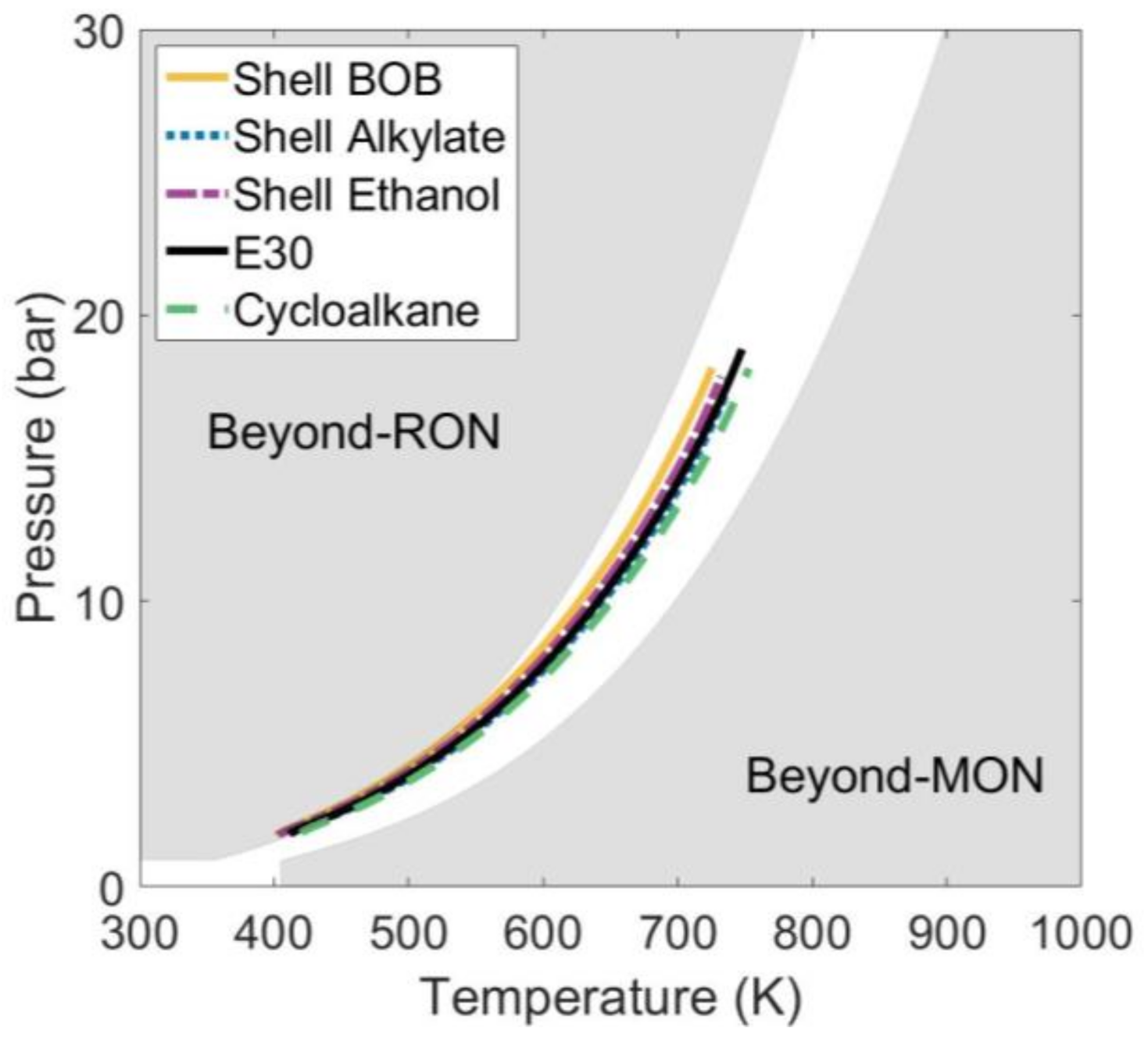
The resulting PT trajectories from the four SI operating conditions are shown in Figure 3 for select fuels, where the trajectories starting at intake valve closing (IVC) and ending at spark timing for the most retarded combustion phasing using the temperature calculation discussed in the experimental setup section, with spark timing occurring at more than 10 °CA aTDCf. The reference lines for the RON and MON tests on this plot were taken from Szybist et al. [37]. As expected, the PT trajectory of the boosted operating condition is in the beyond-RON regime, meaning that for a given pressure, the in-cylinder temperature is lower than that of the RON test. As the intake temperature increases for the part-MON and the MON-like cases, the PT trajectories approach and exceed the MON test. Finally, the part-load condition is the furthest beyond MON, which is consistent with the notional model of PT trajectory described by Szybist et al. [37], and consistent with other previous investigations [21,22,25,37,38].
While the PT trajectories do lie within the beyond RON domain for the boosted SI condition, they are closer to the RON condition than has been shown for earlier investigations [21,22,25]. This is due to the engine used in this investigation being more knock-prone than that of earlier investigations [21,22,25], which is largely a result of its higher compression ratio (12.5:1 vs. 9.2:1). As a consequence, the engine is only modestly boosted with the maximum level of boost limited to approximately 120 kPa absolute at 1500 rpm, as can be seen in Table 2.
With the exception of the part-load condition, the trajectories in Figure 3 contain conditions that exhibit very late combustion phasing, in which the spark occurs after TDC. Thus, in the absence of heat release prior to the spark, we expect to see a ‘cooling hook’ at the end of the PT trajectory, where maximum pressure is achieved just prior to TDC. Because of heat losses, the temperature of the in-cylinder contents are lower during the initial portion of the expansion stroke than they were during compression. This is the behavior observed for the part-MON and MON-like conditions, but there are notable exceptions to this for boosted operating condition. Specifically, while E30 does produce a ‘cooling hook,’ the cycloalkane fuel shows essentially no heat losses. Further, both the Shell Ethanol and Shell Alkylate show a temperature increase at the end of the PT trajectory. For the Shell Alkylate, this temperature rise is on the order of 75 K. The temperature increase is the result of pre-spark heat release (PSHR) and is caused by low-temperature oxidation chemistry, which is consistent with several previous investigations [21,22,39,40].
The PSHR behavior at the boosted SI condition is also visible when examining the cylinder pressure and heat release rate, as shown in Figure 4. PSHR is visible as the lower magnitude peak in heat release prior to the spark for the boosted condition, and to a lesser degree for the part-MON conditions. A magnified view of the PSHR events can be seen in the inset graphs next to the heat release rate plots in Figure 4.
Prior kinetic modeling investigations have established that PSHR events can be attributed to LTHR chemistry [23,40], a result of alkylperoxy radical chain-branching fuel oxidation reactions [12,41,42,43,44,45], followed by a negative temperature coefficient (NTC) regime [41,42,44,45] where reaction rates decrease as temperature increases. LTHR typically occurs with fuels that have low Soctane, low octane ratings, or both and is related to fuel molecular structure due to internal isomerization being a key mechanistic step [41,45]. The high temperature heat release (HTHR) autoignition reactions that can occur after LTHR are associated with knock in SI engines. Nevertheless, in normal SI combustion, the fuel and air mixture is consumed by a propagating flame front before HTHR autoignition occurs.
Several observations can be drawn by examining the PSHR events in Figure 4. The most prominent feature is the decreasing extent of PSHR reactions with increasing intake temperature. The magnitude of the PSHR events decrease as the intake temperature is raised. Figure 4 shows the Shell Alkylate fuel has a peak LTHR heat release rate at the boosted condition event of 8 J/°CA, which drops to 1 J/°CA for the part-MON condition, and to negligible levels for the MON-like condition. A second trend is the increasingly advanced phasing of the PSHR event with increased intake temperature. The location of the peak of the PSHR event with the Shell Alkylate fuel advances from 2 °CA to 10 °CA bTDCf moving from boosted to part-MON operation. Elevating the intake temperature acts by shifting the PT curve, suggesting that pressure and temperature conditions conducive to LTHR chemistry are reached earlier in the compression stroke, and at a lower pressure. Due to the pressure sensitivity of the kinetics responsible for LTHR, the magnitude of PSHR decreases as a result [12,41,43]. Comparing the PSHR rates for boosted operation between the Cycloalkane and E30 fuels shows that the Cycloalkane exhibits some low temperature oxidation reactions. However, unlike the Shell Ethanol and Alkylate fuels, the PSHR event for the Cycloalkane is not separated (i.e., there is no local maximum) from the deflagration heat release event, illustrating that it has not entered the NTC region before being obscured by heat release associated with flame propagation.
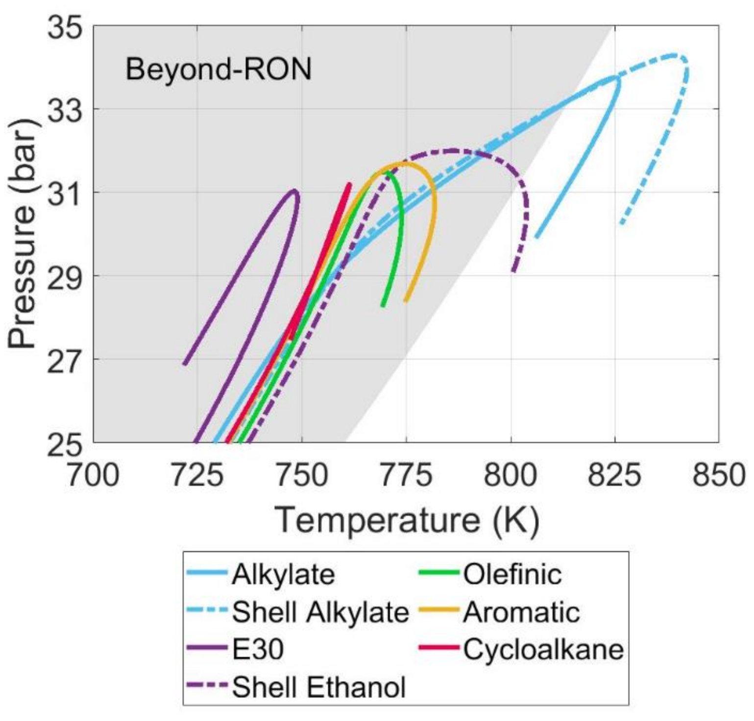
Several additional Co-Optima fuels demonstrated PSHR for boosted operation. A detailed view of the PT trajectories for all fuels run under the boosted SI condition are shown in Figure 5. While PSHR is expected from the Co-Optima Alkylate fuel due to low Soctane, these results illustrate all fuels except E30 exhibit some level of PSHR under boosted conditions. Figure 6 further demonstrates that even for the Co-Optima core fuels with the same RON and high Soctane, some level of PSHR can be detected for the olefin, aromatic, and cycloalkane formulations. This shows that PSHR can occur with a variety of fuel formulations with different chemistries under the right thermodynamic conditions. Vuilleumier et al. [38] similarly observed PSHR with the Alkylate, Aromatic, and E30 Co-Optima gasolines at intake pressure slightly above ambient and 12:1 compression, however this did not include the Cycloalkane or Olefinic fuels.

3.2. ACI Combustion Performance

The two ACI strategies investigated, SACI and PFS, utilize multiple fuel injections to stratify the fuel and air, but the stratification is used for different purposes. The SACI combustion process utilizes a spark-initiated deflagration event to compression-autoignite the remainder of the unburned fuel-air mixture ahead of the flame front, which is dilute [28,29,30]. The amount of fuel that is consumed by the deflagration event can change with the engine operating condition [29,30], and can take place under fuel-lean or EGR-dilute conditions. However, it is well known that dilute conditions result in slow flame speed, which then cause an increased level of cycle-to-cycle variability [46]. Thus, SACI uses multiple injections to create fuel stratification such that there is a region near the spark plug that has a higher fuel-concentration to promote reliable deflagration, and the end gas that is compression ignited is more dilute. As a result, the second fuel injection timing and spark timing under SACI conditions are moved in unison. Two fuels required modifications for the standard SACI operating procedure outlined in the methodology section. The Shell BOB fuel exceeded the pressure rise limits at a minimum temperature of 35 °C at standard 2nd injection and spark timings of 32 °CA and 26 °CA. As a result, the 2nd injection event and spark were retarded until 26 °CA and 20 °CA, respectively, so that the PRR limit was not exceeded. In addition, the high volatility of iso-octane required a decrease in the separation between the 2nd injection and spark events from 6 °CA to 4 °CA to ensure an adequate level of stratification near the spark plug during the spark event. For all fuels, retarding the paired fuel injection and spark timing retarded combustion phasing.
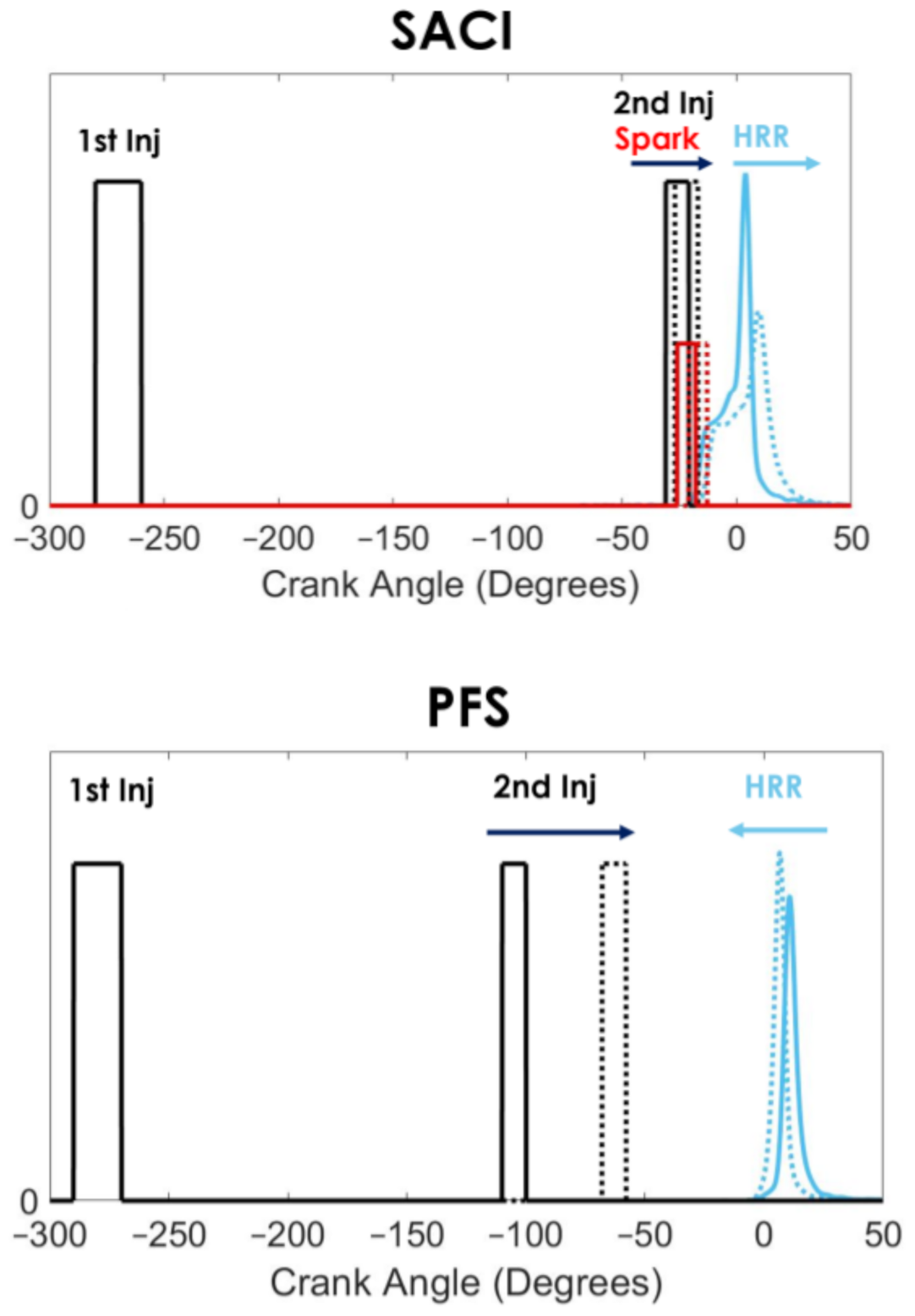
Alternately, unlike SACI, PFS relies on autoignition of the entire fuel-air charge, similar to HCCI combustion. However, incorporating some fuel-air stratification creates a reactivity gradient throughout the mixture because the autoignition delay is dependent on the equivalence ratio [7,8,13,14,27]. It has been shown that the reactivity gradient generated by differences in equivalence ratio, or phi-sensitivity, is an important fuel property for PFS operation that is not well-captured by conventional autoignition metrics, and is helpful in temporally distributing the heat release rate of the fuel-air mixture, thereby decreasing the PRR [8,27]. Thus, relative to SACI operation, the PFS strategy employed here utilizes a leaner fuel-air mixture (λPFS = 3.0; λSACI = 2.0), and utilizes a second fuel injection event that is substantially earlier than that of SACI, as can be seen in Table 2. Further, as can be seen in Figure 7, in contrast to SACI combustion, retarding the second fuel injection advances combustion phasing for PFS operation because it produces a steeper equivalence ratio gradient. The contrasting trends in operation relative to the 2nd injection event can be seen in Figure 7.
The PT trajectory for PFS operation represents a significant deviation from the prior SI points. The trajectories for the same five selected fuels, previously shown in Figure 3, are shown under PFS operation at a CA50 combustion phasing of 10° aTDCf in Figure 8. The PT trajectories begin at intake valve closing and end at TDC. Two major differences are the significantly higher peak pressure levels prior to combustion and the greater spread between the trajectories of the respective fuels. These differences can be attributed to the operating parameters for PFS operation. The spread between the trajectories is due to the differences in IVC temperature caused by adjusting the intake temperature between 61–177 °C to set the combustion phasing for each fuel. Similarly, the higher peak pressure is due to the high level of intake boosting required to achieve autoignition. The Shell BOB, and to a lesser extent Shell Alkylate fuels demonstrate LTHR for PFS operation, visible as a change in direction of the PT trajectories above a pressure of 30 bar and at temperatures between 750 K and 850 K in Figure 8. A notable byproduct of the LTHR event is that the temperature gap is closed between these fuels and the ethanol-containing fuels. In effect, the LTHR events counteract the lower intake temperature requirements of the Shell BOB and Shell Alkylate fuels such that all the fuels have a similar temperature at TDC, with the exception of the Cycloalkane. This behavior stands in contrast to boosted SI operation, where PSHR adds dispersion to the PT trajectories prior to combustion. PFS further contrasts to boosted SI operation due to the PT history lying closer to RON-like conditions, despite the much higher intake boosting levels. Increasing intake temperatures from 61 °C for the Shell BOB to 177 °C for the Cycloalkane fuel expectedly shifts the PT curve to a higher temperature for a given pressure, explaining why the trajectory lies closer to RON-like operation.
Pressure-temperature trajectories for SACI operation begin at intake valve closing and end at the spark timing required for a CA50 of 5 °CA aTDCf, as shown in Figure 9. In contrast with the PFS trajectories, there is less spread for the same group of fuels due to the smaller 35–77 °C range of intake temperatures used. The comparatively lower intake heating requirements for SACI are due to the deflagration event providing a large portion of the pressure and temperature rise necessary to promote autoignition. The reliance on a spark event to initiate heat release instead of autoignition means that the combustion event also occurs much earlier in the cycle. As a result, the pressure and temperature levels prior to combustion are lower for SACI, which is why no LTHR is visible in these PT traces. Similar to PFS, the PT trajectories for SACI operation are at a higher temperature for a given pressure than for boosted SI operation. While the intake temperatures are lower than for PFS, the trajectories lie between the RON and MON conditions, which can be attributed to the lower intake manifold pressure for the SACI combustion relative to PFS, due to the lower λ required for SACI operation.
The cylinder pressures and heat release rates that correspond to the PT trajectories shown in Figure 8; Figure 9 are shown in Figure 10 for the same fuels and combustion phasing conditions. For PFS operation, cylinder pressures prior to combustion were on the order of 50 bar and peak cylinder pressures for PFS approached 70 bar, but the fuel-specific variability was small. In contrast, the peak cylinder pressure for SACI combustion exhibited a higher level of variability at a constant CA50 combustion phasing, from 57 bar to 65 bar. Examining the heat release rates for PFS shows that while some fuels exhibit LTHR, similar to boosted operation in Figure 4, the main HTHR autoignition event is similar for all fuels, thus resulting in only minimal variability in peak cylinder pressure. The main combustion events in Figure 10a resemble the sequential autoignition and rapid combustion experienced with HCCI. The peak heat release rates exceed 90 J/deg, reaching up to 110 J/deg for the fuels not experiencing LTHR. The differences in heat release rates are more significant for the same fuels under SACI operating conditions and can explain the larger fuel-to-fuel differences in peak pressure noted earlier. While the heat released in the initial deflagration event is similar in magnitude between the fuels, about 20 J/°CA, heat release rates have a much higher degree of variation after bulk autoignition, with peak heat release rates varying from 35 J/°CA up to nearly 90 J/°CA. Another notable feature from Figure 10b is the bulk-autoignition point for each fuel. Notably the Shell BOB fuel has the earliest autoignition timing, which occurs when 34% of the total charge is burned, followed by the Shell Alkylate, reaching autoignition at 42% mass fraction burned (MFB). The Shell Ethanol, E30, and Cycloalkane fuels have similar bulk-autoignition points at an MFB of approximately 50%. Aside from the Shell BOB, which was not operable under boosted SI conditions, the Shell Alkylate is the fuel that produces the highest level of LTHR for both the boosted SI condition and PFS, and is the same fuel that has the earliest autoignition under SACI conditions.
While PSHR cannot be observed in the heat release rate for SACI (Figure 10b), there is ample evidence to suggest that it occurs and is obscured by the deflagration heat release. Modeling by Kim et al. [47] illustrated that there was LTHR in the end-gas prior to bulk autoignition during SACI, and that the LTHR plays a central role in determining the timing of the SACI autoignition event. Kim et al. [47] also showed that fuels with low Soctane, such as the Co-Optima Alkylate, experienced progressively stronger LTHR as the zone temperatures decrease with thermal stratification due to their NTC behavior. The net effect of this behavior is an increasing temperature rise as the zones become progressively colder, and a reduction in the level of thermal stratification, thereby producing a more rapid combustion event. Given these findings, the low Soctane and octane ratings of the Shell BOB and Alkylate fuels mean they are expected to produce stronger LTHR and more intense HTHR, agreeing with the experimental results seen in Figure 10b. Additionally, the early autoignition timing for these fuels means a greater fraction of the total fuel is burned in the faster kinetically-driven combustion, thereby producing higher heat release rates upon autoignition. However, the 2nd injection and spark timings required to reach a CA50 of 5 °CA varied by fuel, creating differences in mixture formation and end-gas temperatures that could influence the autoignition timing and post-autoignition rates.
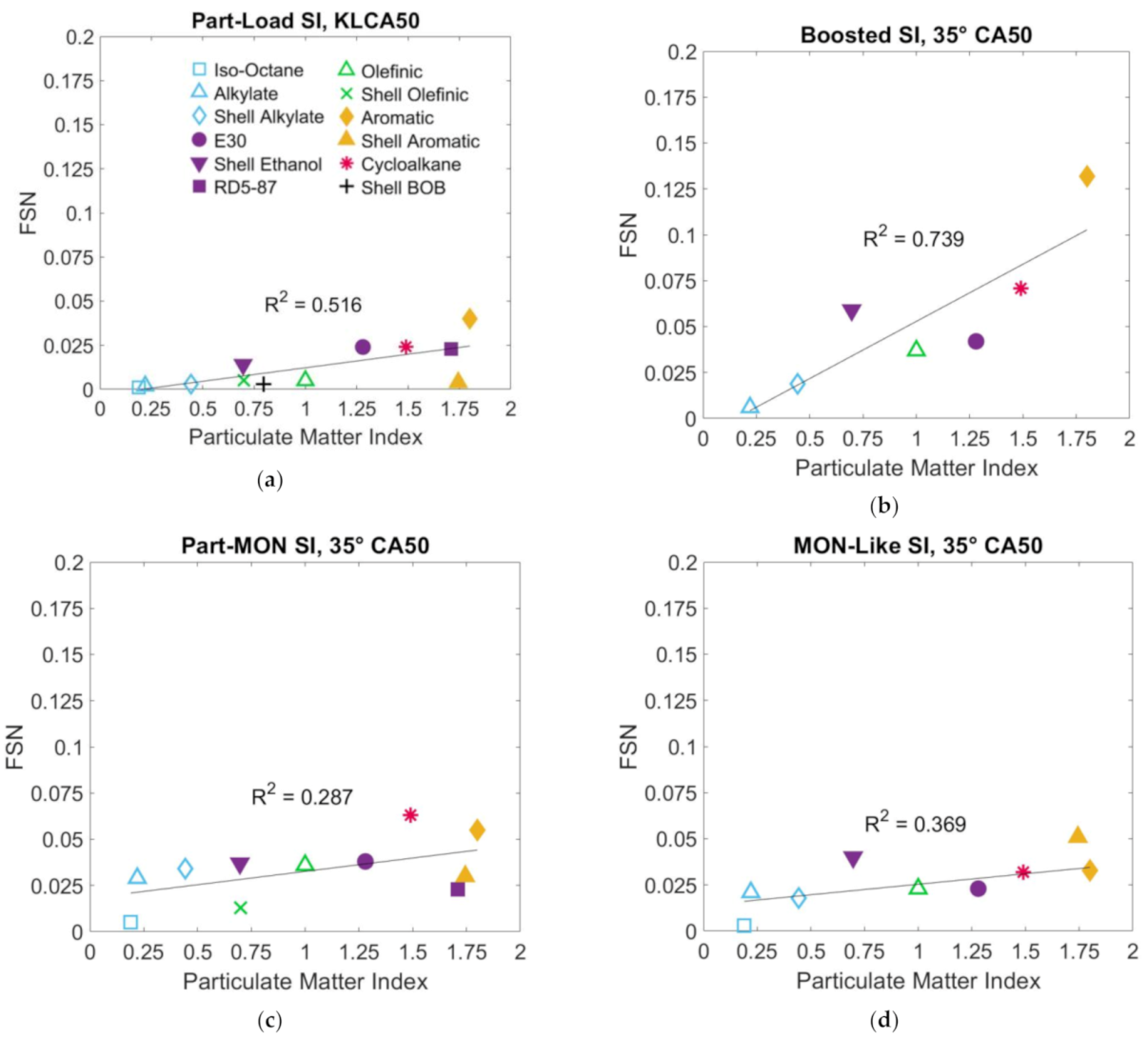
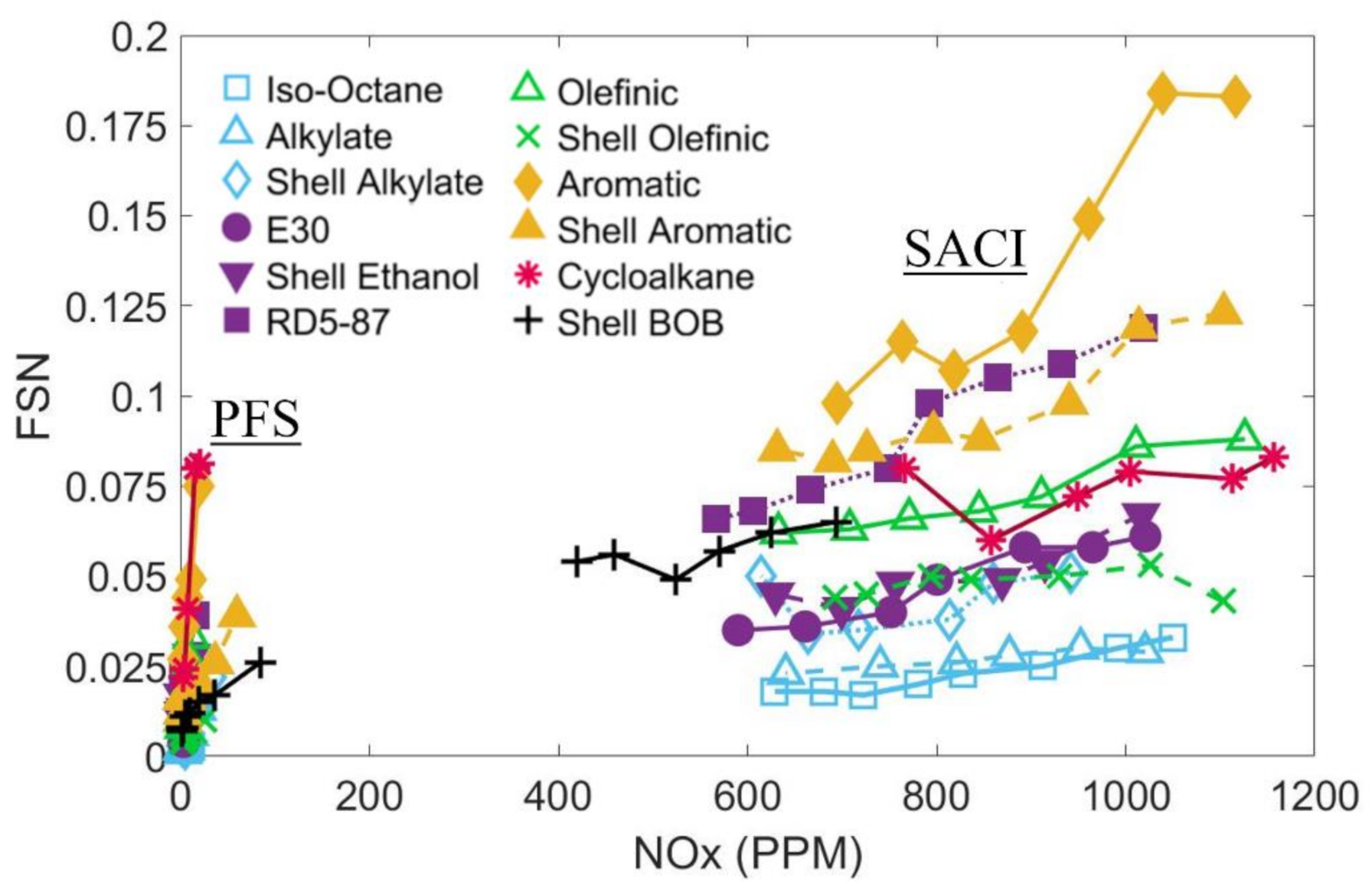
Both PFS and SACI are dependent on compositional stratification, but their differing methods of initiating combustion lead to sizeable differences in NOx and soot emissions. The soot-NOx tradeoff and soot emissions for both ACI modes are shown in Figure 11 and Figure 12, respectively. PFS operation has a lower global air-fuel ratio (λ = 3), and the second fuel injection timing occurs earlier in the cycle (see Figure 7), and thus the stratified portions of the mixture have more time to mix relative to SACI combustion. As a result, the soot-NOx tradeoff (Figure 11) shows the NOx emissions for the PFS are roughly an order of magnitude lower than SACI NOx emissions, and smoke emissions are roughly half those of SACI. For PFS, NOx emissions depend on the most advanced combustion phasing each fuel can achieve, while the NOx levels are more fuel-independent for SACI. In Figure 12, the smoke emissions are plotted as a function of the particulate matter index (PMI), which is a fuel property originally developed by Aikawa et al. [48] that attributes a sooting propensity for each component of the fuel based on vapor pressure and double bond equivalence. The PMI values for each fuel investigated are included in Table 3. It can be seen in that both ACI conditions, as well as for the SI conditions shown in the Appendix A, smoke emissions correlate reasonably with PMI, with the high aromatic fuels producing the highest soot levels. However, the inconsistent prediction of smoke emissions for the cycloalkane, RD5-87, and E30 fuels between the two ACI modes makes it difficult to infer fuel-specific soot trends. Figure A1 in the Appendix A gives the smoke emissions as a function of PMI for each of the SI operating conditions.

3.3. Octane Index and Measured Fuel Autoignition Resistance

As described in the Introduction section, a motivation for this work was to determine if the fuel chemistry-specific trends observed by Szybist et al. [25] could be repeated with more production-relevant ACI combustion strategies, and fuel chemistry more representative of refinery blending streams. To do this, OI and the corresponding K factor were calculated in the same manner as the previous work. That is, for the SI combustion modes, the knock limited CA50 combustion phasing was used, and for the ACI modes, the intake air temperatures at the baseline operating conditions, as described in the methodology section, were used. In both cases, OI and K were calculated using the linear regression method in accordance with Kalghatgi [20] and shown in Equations (1) and (2). The K-value has been shown to correlate with the PT trajectory, where values greater than unity correlate to the beyond-MON space, and values less than zero correlate to the beyond-RON space [20,25,37]. K-values between zero and one correlate to the space between the RON and MON PT trajectories.
OI = a RON + b MON + c
K = b a + b
The K-value from the OI correlation, as well as the R2 correlation coefficients for actual performance relative to OI and RON are shown in Table 4. The correlation of autoignition resistance to OI is improved over RON in all cases, however the level of improvement varies with the K value. By definition, OI = RON when K = 0. As a result, for the conditions where K is close to zero (boosted SI and part-MON), the R2 correlation coefficient for RON approaches that of OI.
The knock limited combustion phasing as a function of OI at each of the four SI conditions are shown in Figure 13. The PT trajectory for the throttled operation, Figure 3, lies in the beyond-MON space, and the PT trajectory of for the MON-like condition approaches the PT trajectory of the MON trajectory. Despite this, K < 1 for both of these operating conditions, whereas by definition, K = 1 for the MON test. This finding is consistent with Szybist et al. [25] and illustrates that there are many other differences in engine and operating condition between the knock-limited combustion phasing in this investigation and that of the MON test, including combustion chamber design, engine speed, and combustion phasing. However, for any condition where K > 0, Soctane decreases OI relative to the RON value, and thus low values of Soctane are desirable for these conditions. This provides the highly paraffinic fuels (Iso-octane and Alkylate) with the highest OIs and best knock resistance, including the Shell 95 RON Alkylate fuel outperforming all of the 98-RON E30, Aromatic, Olefinic, and Cycloalkane fuels at the part-load SI condition.
The PT trajectory for the boosted SI condition shown in Figure 3 is marginally beyond-RON, and correspondingly, its K-value of 0.04 is similar to that in the RON test. Increasing the intake temperature to 95 °C for the Part-MON condition, shown in Figure 3, shifts the PT trajectory substantially from the boosted condition to close to the MON test, but produces only a modest shift in K-value, to 0.05. The small shift in K-value runs counter to expectations, especially in light of the values from the prior study [25], where much larger shifts in K-value were observed. These discrepancies can be explained through two major differences with the earlier study. First, as discussed previously, the level of boosting for this engine is limited due to its high compression (12.5:1), and thus the extent of beyond-RON operation. Second, several fuels were not capable of reaching a knock-limited phasing at 35 °CA aTDCf or earlier in this investigation, which resulted in a smaller fuels matrix for several of the SI conditions, including only 7 of 12 fuels being operable under the boosted condition. Rockstroh et al. showed that the K value determination can change significantly for different fuel subsets [49] and Zhou et al. also found that the design of the fuel matrix can have significant impacts on the K-value determination [50]. Similarly, Cracknell et al. found using higher RON fuels, like those in the limited boosted SI fuel matrix, tended to increase the K-value slightly [51]. Thus, the similar K values for the boosted SI and part-MON conditions is likely attributable in part to the differences in the fuels that could be operated at each condition. Overall, though, it can be concluded from Figure 13a–d that OI is capable of providing a good indication of fuel performance under all of the SI conditions investigated.
The homogeneous ACI condition in the prior investigation required intake temperatures of up to 300 °C, which led to a highly beyond-MON condition and a high K-value [25]. The high levels of intake boosting required to operate SACI and PFS in the current study resulted in PT trajectories that were more similar to the RON condition. As a result, the respective K-values for the PFS and SACI conditions are −0.41 and −0.33. Relative to the prior study where the ACI K >1, and thus Soctane led to lower OI and were more prone to autoignition, the negative K-values for the ACI conditions investigated here led to higher Soctane fuels having higher OI and being more resistant to autoignition compared to lower Soctane fuels. The high R2 correlation coefficients for OI, shown in Table 4, illustrate that autoignition resistance is equally well-described for the ACI conditions investigated here. There are no evident patterns in fuel autoignition resistance by fuel chemical class for the SACI or PFS conditions, except that the Olefin fuels were consistently the easiest to autoignite (Figure 13e,f). The cycloalkane fuel is also consistently the most difficult to autoignite, however it is difficult to determine a fuel-chemistry trend with only one fuel of this chemical class. The overall lack of fuel chemistry effects independent of the measured fuel properties deviates from what Szybist et al. [25] experienced with the beyond-MON homogeneous ACI condition, with the exception of both investigations finding that the olefinic fuels were consistently the easiest to autoignite. However, the magnitude of chemistry-specific differences observed in this study in Figure 13 are minor compared to the findings of the previous study.

4. Discussion

The PT trajectories of the SACI and PFS conditions investigated here were found to be in close proximity to the RON trajectory, with some individual cases extended into the beyond-RON domain, due to their high intake boosting requirements. In comparison, the prior study used a homogeneous ACI mode that had a strongly beyond-MON trajectory due the high intake temperatures required. These two investigations demonstrate that a wide range of combustion strategies, operating conditions, and PT trajectories are encompassed under the classification of multi-mode ACI operation.
One of the aims of this study was to evaluate the effect of fuel chemistry on the accuracy of the OI metric for ACI operation. In the prior investigation, deviations in autoignition behavior corresponding to fuel chemical classes were found at the beyond-MON conditions, where LTHR is suppressed due to the favored reactions under those high-temperature thermodynamic conditions. Under the conditions where LTHR was suppressed, accuracy of the OI metric was degraded and the importance of the different chemical classes was prominent [25]. In the current study, the OI metric agreed with the fuel autoignition resistance for the SACI and PFS ACI modes investigated. There is ample evidence that LTHR plays an outsized role in the relative fuel ranking for both of these ACI modes: (1) The PT trajectories are shown to be similar to the RON test in Figure 8; Figure 9, (2) the visualization of LTHR for PFS in Figure 10, and (3) a determination of K < 0 in Table 4. Thus, for the ACI modes investigated here, LTHR chemistry governs autoignition and the relative fuel ranking, similar to knock under boosted SI operation.
These observations indicate that both the applicability of the OI metric and fuel response depend strongly on the ACI strategy and chosen operating conditions. Given the highly boosted nature of both PFS and SACI ACI modes, the optimal fuels for each of the ACI combustion strategies are fuels having a low octane rating, low Soctane, or both due to the presence of LTHR and its beneficial effect on reducing the required intake temperature. However, for an ACI operating strategy that relies on a temperature-driven beyond-MON combustion strategy, which can be achieved using a negative valve overlap or exhaust rebreathing strategy, LTHR is suppressed and the desired fuel candidates can change significantly, preferring fuels with high Soctane.

5. Conclusions

The purpose of this study was to further investigate the accuracy of the OI metric, and to determine if fuel chemistry differences not captured in the RON and MON tests plays a dominant role in determining fuel autoignition resistance. A total of 12 fuels were investigated, including the five Co-Optima fuels, five fuels custom-blended by Shell from refinery-relevant streams, a market-representative E10 fuel, and iso-octane. Some Co-Optima fuels contain large concentrations of single components while the Shell fuels contain multiple components from the same fuel chemical family. This was intended to determine whether the observed deviation from the OI metric in the prior investigation was due to the individual components, or the chemical families they belong to [25]. Fuel autoignition resistance was then investigated across PT trajectories spanning the beyond-RON space to the beyond-MON space for SI and two ACI combustion modes. Several trends were observed:
  • Fuels with low octane ratings and low Soctane displayed LTHR for ACI operation and PSHR for SI operation. In this investigation, all PSHR that occurred coincided with the 750–850 K temperature range that characterizes LTHR. Higher intake temperatures attenuate the PSHR magnitude by passing through this temperature range at lower pressures, suppressing the oxidation chemistry responsible for LTHR. While low Soctane fuels typically have the greatest levels of LTHR, fuels with Soctane as high as 10.9 exhibited PSHR under boosted SI conditions.
  • While the LTHR isn’t observed prior to deflagration during SACI combustion, the post-autoignition combustion rate was highest for the fuels demonstrating the greatest LTHR magnitudes for other combustion modes, thereby providing evidence of LTHR in the end-gas region that is obscured by the deflagration event.
  • The LTHR magnitude by fuel chemical family at boosted SI conditions was identical to those at PFS conditions. The ranking from greatest LTHR magnitude to the least is paraffins > aromatic > olefin > cycloalkane > ethanol for a given RON rating.
  • The moniker “multimode ACI” encompasses a broad range of combustion strategies and PT trajectories. ACI operation in the prior study had a strongly beyond-MON trajectory, and it showed the importance of chemical composition. The SACI and PFS strategies in the current investigation are closer to the RON trajectory, and exhibited a strong dependence on LTHR, which is similar to the knock dependencies for boosted SI combustion. As a result, the SI and ACI combustion strategies investigated here align much better with OI predictions, illustrating that fuel response is highly dependent on the ACI strategy being used.
  • The OI metric is broadly capable of accurately predicting fuel autoignition resistance for SI combustion across a wide range of the PT domain and ACI modes operating at or near RON-like conditions. Similarly, the OI metric is also capable of predicting autoignition resistance ordering for fuels of varying chemical families.
  • While the OI metric is adequate for describing autoignition resistance, olefinic fuels were consistently easier to autoignite for ACI operation, but those differences were minor relative to the chemistry-specific differences from the prior investigation [25].

Author Contributions

Conceptualization, J.P.S., J.M., A.A. and R.C.; methodology, T.R.P., J.P.S., F.D.F.C., S.J.C., J.M., A.A. and R.C.; software, T.R.P.; validation, T.R.P. and J.P.S.; formal analysis, T.R.P. and J.P.S.; investigation, T.R.P. and F.D.F.C.; resources, J.P.S. and A.A.; data curation, T.R.P.; writing—original draft preparation, T.R.P. and J.P.S.; writing—review and editing, T.R.P., J.P.S., F.D.F.C., S.J.C., J.M., A.A. and R.C.; visualization, T.R.P. and J.P.S.; supervision, J.P.S. and S.J.C.; project administration, J.P.S.; funding acquisition, J.P.S. All authors have read and agreed to the published version of the manuscript.

Funding

This research was funded by the U.S. Department of Energy (DOE) Office of Energy Efficiency and Renewable Energy (EERE) as part of the Co-Optimization of Fuels and Engines (Co-Optima) initiative.

Data Availability Statement

The data presented in this study are available on request from the corresponding author.

Acknowledgments

This research was conducted as part of the Co-Optima Initiative sponsored by the U.S. DOE EERE, Bioenergy Technologies and Vehicle Technologies Offices. Co-Optima is a collaborative Initiative of multiple National Laboratories initiated to simultaneously accelerate the introduction of affordable, scalable, and sustainable biofuels and high-efficiency, low-emission vehicle engines. A special thanks to Kevin Stork, Gurpreet Singh, and Mike Weismiller. We would also like to thank GM for their engine hardware support, particularly Arun Solomon and Paul Najt.

Conflicts of Interest

The authors declare no conflict of interest.

Disclaimer

This manuscript has been authored by UT-Battelle, LLC, under Contract No. DE-AC0500OR22725 with the U.S. Department of Energy. The United States Government retains and the publisher, by accepting the article for publication, acknowledges that the United States Government retains a non-exclusive, paid-up, irrevocable, world-wide license to publish or reproduce the published form of this manuscript, or allow others to do so, for the United States Government purposes. The Department of Energy will provide public access to these results of federally sponsored research in accordance with the DOE Public Access Plan (http://energy.gov/downloads/doe-public-access-plan).

Definitions and Abbreviations

ACIAdvanced compression ignition
AFRAir to fuel ratio
AKIAnti-knock index
aTDCfAfter firing top dead center
BMEPBrake mean effective pressure
BOBBlendstock for oxygenate blending
bTDCfBefore firing top dead center
CACrank angle
CA50Crank angle of 50% heat release
DHADetailed hydrocarbon analysis
DIDirect injection
HCCIHomogeneous charge compression ignition
IMEPIndicated mean effective pressure
KOctane index constant representing engine operating condition
LTHRLow-temperature heat release
MONMotor octane number
NOxOxides of nitrogen
NTCNegative temperature coefficient
OIOctane index
PFSPartial fuel stratification
PMIParticulate matter index
PRRPressure rise rate
PTPressure-temperature
R2Correlation coefficient
RONResearch octane number
SACISpark-assisted compression ignition
SoctaneOctane sensitivity
SISpark ignited
γRatio of specific heats

Appendix A. SI Smoke Emissions

Figure A1. Octane index for fuels under (a) part-load SI, (b) boosted SI, (c) part-MON SI, (d) MON-like SI operation.
Energies 14 00607 g0a1

References

  1. Szybist, J.P.; Busch, S.; McCormick, R.L.; Pihl, J.A.; Splitter, D.A.; Ratcliff, M.A.; Kolodziej, C.P.; Storey, J.E.; Moses-Debusk, M.; Vuilleumier, D.; et al. What Fuel Properties Enable Higher Thermal Efficiency in Spark-Ignited Engines? Prog. Energy Combust. Sci. 2021, 82, 100876. [Google Scholar] [CrossRef]
  2. Heywood, J.B. Internal Combustion Engine Fundamentals, 1st ed.; McGraw-Hill Inc.: New York, NY, USA, 1988. [Google Scholar]
  3. Jo, Y.S.; Bromberg, L.; Heywood, J. Octane Requirement of a Turbocharged Spark Ignition Engine in Various Driving Cycles. SAE Tech. Pap. 2016. [Google Scholar] [CrossRef]
  4. Smith, P.; Cheng, W.K. Assessing the Loss Mechanisms Associated with Engine Downsizing, Boosting and Compression Ratio Change. SAE Tech. Pap. 2013. [Google Scholar] [CrossRef]
  5. Thring, R.H. Homogeneous-Charge Compression-Ignition (HCCI) Engines. SAE Tech. Pap. 1989. [Google Scholar] [CrossRef]
  6. Dec, J.E. Advanced Compression-Ignition Engines—Understanding the in-Cylinder Processes. Proc. Combust. Inst. 2009, 32, 2727–2742. [Google Scholar] [CrossRef]
  7. Yang, Y.; Dec, J.; Dronniou, N.; Sjöberg, M.; Cannella, W. Partial Fuel Stratification to Control HCCI Heat Release Rates: Fuel Composition and Other Factors Affecting Pre-Ignition Reactions of Two-Stage Ignition Fuels. SAE Int. J. Engines 2011, 4, 1903–1920. [Google Scholar] [CrossRef]
  8. Gentz, G.; Dernotte, J.; Ji, C.; Pintor, D.L.; Dec, J. Combustion-Timing Control of Low-Temperature Gasoline Combustion (LTGC) Engines by Using Double Direct-Injections to Control Kinetic Rates. SAE Tech. Pap. 2019. [Google Scholar] [CrossRef]
  9. Chang, J.; Güralp, O.; Filipi, Z.; Assanis, D.N.; Kuo, T.; Najt, P.; Rask, R. New Heat Transfer Correlation for an HCCI Engine Derived from Measurements of Instantaneous Surface Heat Flux. SAE Tech. Pap. 2004. [Google Scholar] [CrossRef] [Green Version]
  10. Eng, J.A. Characterization of Pressure Waves in HCCI Combustion. SAE Tech. Pap. 2002. [Google Scholar] [CrossRef]
  11. Dec, J.E.; Yang, Y. Boosted Hcci for High Power without Engine Knock and with Ultra-Low NOx Emissions—Using Conventional Gasoline. SAE Int. J. Engines 2010, 3, 750–767. [Google Scholar] [CrossRef]
  12. Silke, E.J.; Pitz, W.J.; Westbrook, C.K.; Sjöberg, M.; Dec, J.E. Understanding the Chemical Effects of Increased Boost Pressure under HCCI Conditions. SAE Int. J. Fuels Lubr. 2009, 1, 12–25. [Google Scholar] [CrossRef]
  13. Sjöberg, M.; Dec, J.E. EGR and Intake Boost for Managing HCCI Low-Temperature Heat Release over Wide Ranges of Engine Speed. SAE Trans. 2007, 116, 65–77. [Google Scholar]
  14. Dec, J.E.; Yang, Y.; Dronniou, N. Boosted HCCI—Controlling Pressure-Rise Rates for Performance Improvements Using Partial Fuel Stratification with Conventional Gasoline. SAE Int. J. Engines 2011, 4, 1169–1189. [Google Scholar] [CrossRef]
  15. Boldaji, M.R.; Sofianopoulos, A.; Mamalis, S.; Lawler, B. Effects of Mass, Pressure, and Timing of Injection on the Efficiency and Emissions Characteristics of TSCI Combustion with Direct Water Injection. SAE Tech. Pap. 2018. [Google Scholar] [CrossRef]
  16. Sjöberg, M.; Dec, J.E.; Babajimopoulos, A.; Assanis, D. Comparing Thermal Stratification Against Retarded Combustion Phasing for Smoothing of HCCI Heat-Release Rates. SAE Trans. 2004, 113, 1557–1575. [Google Scholar]
  17. Foong, T.M. On the Autoignition of Ethanol/Gasoline Blends in Spark-Ignition Engines. Ph.D. Thesis, University of Melbourne, Melbourne, Australia, 2013. [Google Scholar]
  18. ASTM D2699-16e1. Standard Test Method for Research Octane Number of Spark-Ignition Engine Fuel; ASTM International: West Conshohocken, PA, USA, 2016. [Google Scholar]
  19. ASTM D2700-16a. Standard Test Method for Motor Octane Number of Spark-Ignition Engine Fuel; ASTM International: West Conshohocken, PA, USA, 2016. [Google Scholar]
  20. Kalghatgi, G.T. Fuel Anti-Knock Quality-Part I. Engine Studies. SAE Trans. 2001, 110, 1993–2004. [Google Scholar] [CrossRef]
  21. Szybist, J.P.; Splitter, D.A. Understanding Chemistry-Specific Fuel Differences at a Constant RON in a Boosted SI Engine. Fuel 2018, 217, 370–381. [Google Scholar] [CrossRef]
  22. Szybist, J.P.; Splitter, D.A. Pressure and Temperature Effects on Fuels with Varying Octane Sensitivity at High Load in SI Engines. Combust. Flame 2017, 177, 49–66. [Google Scholar] [CrossRef]
  23. Splitter, D.A.; Gilliam, A.; Szybist, J.; Ghandhi, J. Effects of Pre-Spark Heat Release on Engine Knock Limit. Proc. Combust. Inst. 2019, 37, 4893–4900. [Google Scholar] [CrossRef]
  24. Tao, M.; Zhao, P.; Szybist, J.P.; Lynch, P.; Ge, H. Insights into Engine Autoignition: Combining Engine Thermodynamic Trajectory and Fuel Ignition Delay Iso-Contour. Combust. Flame 2019, 200, 207–218. [Google Scholar] [CrossRef]
  25. Szybist, J.P.; Splitter, D.A. Impact of Engine Pressure-Temperature Trajectory on Autoignition for Varying Fuel Properties. Appl. Energy Combust. Sci. 2020. [Google Scholar] [CrossRef]
  26. Fouts, L.A.; Fioroni, G.M.; Christensen, E.D.; Ratcliff, M.A.; McCormick, R.L.; Zigler, B.T.; Sluder, S.; Szybist, J.P.; Dec, J.E.; Miles, P.C.; et al. Co-Optimization of Fuels & Engines: Properties of Co-Optima Core Research Gasolines; Technical Report for NREL/TP-5400-71341; National Renewable Energy Laboratory: Golden, CO, USA, 2018. [Google Scholar]
  27. Pintor, D.L.; Dec, J.; Gentz, G. φ-Sensitivity for LTGC Engines: Understanding the Fundamentals and Tailoring Fuel Blends to Maximize This Property. SAE Tech. Pap. 2019. [Google Scholar] [CrossRef]
  28. Manofsky, L.; Vavra, J.; Assanis, D.; Babajimopoulos, A. Bridging the Gap between HCCI and SI: Spark-Assisted Compression Ignition. SAE Tech. Pap. 2011. [Google Scholar] [CrossRef]
  29. Szybist, J.P.; Nafziger, E.; Weall, A. Load Expansion of Stoichiometric HCCI Using Spark Assist and Hydraulic Valve Actuation. SAE Int. J. Engines 2010, 3, 244–258. [Google Scholar] [CrossRef]
  30. Weall, A.J.; Szybist, J.P. The Effects of Fuel Characteristics on Stoichiometric Spark-Assisted HCCI. In Proceedings of the ASME 2011 Internal Combustion Engine Division Fall Technical Conference, Morgantown, WV, USA, 2–5 October 2011; pp. 243–259. [Google Scholar]
  31. Woschni, G.A. Universally Applicable Equation for the Instantaneous Heat Transfer Coefficient in the Internal Combustion Engine. SAE Tech. Pap. 1967, 670931, 3065–3077. [Google Scholar]
  32. Yun, H.J.; Mirsky, W. Schlieren-Streak Measurements of Instantaneous Exhaust Gas Velocities from a Spark-Ignition Engine. SAE Tech. Pap. 1974, 83, 3143–3158. [Google Scholar]
  33. Ortiz-Soto, E.; Vavra, J.; Babajimopoulos, A. Assessment of Residual Mass Estimation Methods for Cylinder Pressure Heat Release Analysis of HCCI Engines with Negative Valve Overlap. J. Eng. Gas Turbines Power 2012, 134, 082802. [Google Scholar] [CrossRef]
  34. Sjöberg, M.; Zeng, W. Combined Effects of Fuel and Dilution Type on Efficiency Gains of Lean Well-Mixed DISI Engine Operation with Enhanced Ignition and Intake Heating for Enabling Mixed-Mode Combustion. SAE Int. J. Engines 2016, 9, 750–767. [Google Scholar] [CrossRef]
  35. Xu, C.; Pal, P.; Ren, X.; Sjöberg, M.; Van Dam, N.; Wu, Y.; Lu, T.; McNenly, M.; Som, S. Numerical Investigation of Fuel Propertry Effects on Mixed-Mode Combustion in a Spark-Ignition Engine. J. Energy Resour. Technol. 2021, 143, 1–12. [Google Scholar] [CrossRef]
  36. Olesky, L.K.M.; Middleton, R.J.; Lavoie, G.A.; Wooldridge, M.S.; Martz, J.B. On the Sensitivity of Low Temperature Combustion to Spark Assist near Flame Limit Conditions. Fuel 2015, 158, 11–22. [Google Scholar] [CrossRef] [Green Version]
  37. Szybist, J.P.; Wagnon, S.W.; Splitter, D.; Pitz, W.J.; Mehl, M. The Reduced Effectiveness of EGR to Mitigate Knock at High Loads in Boosted SI Engines. SAE Int. J. Engines 2017, 10, 2305–2318. [Google Scholar] [CrossRef]
  38. Vuilleumier, D.; Sjöberg, M. Significance of RON, MON, and LTHR for Knock Limits of Compositionally Dissimilar Gasoline Fuels in a DISI Engine. SAE Int. J. Engines 2017, 10, 938–950. [Google Scholar] [CrossRef]
  39. Splitter, D.; Kaul, B.; Szybist, J.; Jatana, G. Engine Operating Conditions and Fuel Properties on Pre-Spark Heat Release and SPI Promotion in SI Engines. SAE Int. J. Engines 2017, 10, 1036–1050. [Google Scholar] [CrossRef]
  40. DelVescovo, D.A.; Splitter, D.A.; Szybist, J.P.; Jatana, G.S. Modeling Pre-Spark Heat Release and Low Temperature Chemistry of Iso-Octane in a Boosted Spark-Ignition Engine. Combust. Flame 2020, 212, 39–52. [Google Scholar] [CrossRef]
  41. Westbrook, C.K.; Mehl, M.; Pitz, W.J.; Sjöberg, M. Chemical Kinetics of Octane Sensitivity in a Spark-Ignition Engine. Combust. Flame 2017, 175, 2–15. [Google Scholar] [CrossRef] [Green Version]
  42. Westbrook, C.K.; Mizobuchi, Y.; Poinsot, T.J.; Smith, P.J.; Warnatz, J. Computational Combustion. Proc. Combust. Inst. 2005, 30, 125–157. [Google Scholar] [CrossRef] [Green Version]
  43. Liang, W.; Law, C.K. Theory of First-Stage Ignition Delay in Hydrocarbon NTC Chemistry. Combust. Flame 2018, 188, 162–169. [Google Scholar] [CrossRef]
  44. Zhang, P.; Ji, W.; He, T.; He, X.; Wang, Z.; Yang, B.; Law, C.K. First-Stage Ignition Delay in the Negative Temperature Coefficient Behavior: Experiment and Simulation. Combust. Flame 2016, 167, 14–23. [Google Scholar] [CrossRef]
  45. Leppard, W.R. The Chemical Origin of Fuel Octane Sensitivity. SAE Trans. 1990, 99, 862–876. [Google Scholar]
  46. Szybist, J.P.; Splitter, D. Effects of Fuel Composition on EGR Dilution Tolerance in Spark Ignited Engines. SAE Int. J. Engines 2016, 9, 819–831. [Google Scholar] [CrossRef]
  47. Kim, N.; Vuilleumier, D.; Sjöberg, M.; Yokoo, N.; Tomoda, T.; Nakata, K. Using Chemical Kinetics to Understand Effects of Fuel Type and Compression Ratio on Knock-Mitigation Effectiveness of Various EGR Constituents. SAE Int. J. Adv. Curr. Prac. Mobil. 2019, 1, 1560–1580. [Google Scholar]
  48. Aikawa, K.; Sakurai, T.; Jetter, J.J. Development of a Predictive Model for Gasoline Vehicle Particulate Matter Emissions. SAE Int. J. Fuels Lubr. 2010, 3, 610–622. [Google Scholar] [CrossRef]
  49. Rockstroh, T.; Floweday, G.; Yates, A. Optimisation of Synthetic Gasoline Blend Recipes for Use in Modern Charge Boosted GDI Engines. Fuel 2016, 186, 800–820. [Google Scholar] [CrossRef]
  50. Zhou, Z.; Yang, Y.; Brear, M.; Lacey, J.; Leone, T.G.; Anderson, J.E.; Shelby, M.H. A Comparison of Four Methods for Determining the Octane Index and K on a Modern Engine with Upstream, Port or Direct Injection. SAE Tech. Pap. 2017. [Google Scholar] [CrossRef]
  51. Cracknell, R.; Kassai, M.; Shiraishi, T.; Festa, A.; Gail, S.; Aradi, A.; Shibuya, M. Is the ‘K Value’ of an Engine Truly Fuel Independent? SAE Tech. Pap. 2020. [Google Scholar] [CrossRef]
Figure 1. Intake and exhaust valve timings as a function of cam advance.
Energies 14 00607 g001
Figure 2. Gross IMEP as a function of the CA50 combustion phasing for each of the four SI operating conditions.
Energies 14 00607 g002
Figure 3. Pressure-Temperature trajectories for (a) Boosted, MON-Like, (b) Part-MON, and Light-Load SI points for Shell Alkylate, Shell Ethanol, E30, and High Cycloalkane fuels at 35 °CA aTDCf.
Energies 14 00607 g003
Figure 4. Pressure and heat release for Boosted, Part-MON, and MON-Like SI operation at a phasing of 35 °CA aTDCf, spark timing is 10 ± 1 °CA aTDCf for all cases.
Energies 14 00607 g004
Figure 5. Detailed view of boosted SI PT trajectories showing PSHR tendencies of fuels.
Energies 14 00607 g005
Figure 6. Pre-Spark Heat Release for the Co-Optima fuels for boosted SI operation.
Energies 14 00607 g006
Figure 7. Fuel injection and spark strategies used for SACI combustion (top) and PFS combustion (bottom). For SACI combustion, combustion phasing is delayed with retarded fuel injection timing. For PFS combustion, combustion phasing is advanced with retarded fuel injection timing.
Energies 14 00607 g007
Figure 8. Pressure-Temperature trajectories for PFS operation at 10° CA phasing.
Energies 14 00607 g008
Figure 9. Pressure-Temperature trajectories for SACI at 5° CA phasing, plotted up to the spark event.
Energies 14 00607 g009
Figure 10. Pressure and heat release for (a) PFS operation at 10 °CA aTDCf, and (b) SACI operation at 5 °CA aTDCf.
Energies 14 00607 g010
Figure 11. Soot-NOx tradeoff for PFS and SACI operation.
Energies 14 00607 g011
Figure 12. Smoke emissions, as measured by the filter smoke number (FSN) for (a) PFS and (b) SACI operation.
Energies 14 00607 g012
Figure 13. OI for fuels under (a) part-load SI, (b) boosted SI, (c) part-MON SI, (d) MON-like SI, (e) SACI, and (f) PFS operation.
Energies 14 00607 g013
Table 1. Engine geometry.
Displacement (L)0.550
Bore × Stroke (mm)86.0 × 94.6
Connecting Rod (m)145.5
Compression Ratio12.5:1
Cam PhasingHydraulic phasing, 60 °CA authority for intake and exhaust
Fuel InjectorCentrally-mounted solenoid DI, 8-hole, symmetric 60° included angle
Table 2. Engine Operating Conditions.
ParameterPart Load SIBoosted SIPart-MONMON-LikeSACIPFS
Engine Speed (RPM)150015001500150015001200
Gross Indicated Mean Effective Pressure (IMEP) (kPa)585–6191055–1163744–898688–833599–651576–635
Air flow (g/min)225485350330430500
λ (global)1.01.01.01.02.03.0
Intake Temperature (°C)35359515235–7561–177
Intake Pressure 1 (kPa)73 ± 1120 ± 3102 ± 3103 ± 3159 ± 3177 ± 19
Spark (°CA bTDCf)3.2 to 10.9−6.5 to −10.8−0.2 to −10.7−1.6 to −10.827 to 19.3--
Start of Injection 1st/2nd (°CA bTDCf)280/--280/--280/--280/--280/32–23.3290/110–48
Injection Split 1st/2nd (% injection duration)100/--100/--100/--100/--83/1777/23
CA50 CriteriaKLSA35 °CA aTDCf to KLSA, 5° steps35 °CA aTDCf to KLSA, 5° steps35 °CA aTDCf to KLSA, 5° stepsPRR 10 bar/°CA to 3% COV, 1° stepsPRR 10 bar/°CA to 10° aTDC, 1° steps
Intake/Exhaust Cam Advance (°CA)35/3035/3035/3035/300/6035/50
Estimated Residual (mass %)4.5–5.12.7–2.93.2–3.63.4–3.910.0–11.04.4–5.3
1 Not directly controlled.
Table 3. Fuel Properties.
Co-Optima Core FuelsShell BOB FuelsIso-OctaneRD5-87
PropertyStandardOlefinicE30AromaticAlkylateCycloalkaneBOBAlkylateAromaticOlefinicEthanol
ROND269998.297.498.198.098.087.394.694.895.49510092.3
MOND270088.086.687.896.687.183.390.686.886.687.110084.6
SoctaneCalculated10.210.810.31.410.94488.87.907.7
Saturates (V%)D1319 A/
ISO 22854 B
58.1 A57.1 A65 A100 A70.3 A79 B91.5 B56.9 B62.5 B68.5 B100 A47.4 A
Aromatic (V%)D1319 A/
ISO 22854 B
10.6 A8.1 A30.8 A0 A18.1 A13.3 B5.4 B37.5 B10.3 B11.7 B0 A23.8 A
Olefins (V%)D1319 A/
ISO 22854 B
31.3 A5 A4.2 A0 A1.5 A5.5 B2.3 B4.1 B25.6 B4.8 B0 A5.9 A
Oxygenates (V%)D5589 C/
ISO 22854 B
0 C30.6 C0 C0 C0 C0.1 B0 B0 B0 B13.1 B0 C9.1 C
Ethanol (V%)D5589 C/
ISO 22854 B
0 C30.6 C0 C0 C0 C0 B0 B0 B0 B13.1 B0 C9.1 C
IBP (°C)D8635.7035.7035.7035.7035.7030.240.732.233.23499.340.4
T10 (°C)D8677.160.759.493.1055.762.183.464.965.153.9N/A57.8
T50 (°C)D86104.374.3108.1100.387.4110.899.5117.2100.069.2N/A101.3
T90 (°C)D86136.2155.2157.9105.9142.7163.7112.7160.9132.7139.3N/A157.9
FBP (°C)D86197.7204.1204.4161.3203.5188.8164.8189.3174.6177.299.3205
RVP (PSI)D5191 D/
ISO EN 13016-1 E
42.1 D52.8 D49.4 D28.6 D55.2 D68.7 E72.5 E51.1 E55.8 E72.5 E----
LHV (MJ/kg)D480944.0738.1742.9544.5243.2144.2344.6743.1144.1841.7644.3141.93
Carbon (W%)D529185.4074.7887.2283.7587.0885.1884.5686.8285.2780.4584.2882.67
Hydrogen (W%)D529114.5013.7913.1215.8013.2414.8115.4413.1814.7314.5615.9113.66
Oxygen (W%)D5599011.190000.010004.9903.67
H:CCalculated2.022.21.792.251.812.092.191.822.072.172.251.97
O:CCalculated00.1100000000.04700.033
PMIFCalculated1.001.281.800.221.490.800.441.740.700.700.191.71
AFRstoichCalculated14.8512.9214.5215.1714.5514.9115.0614.5414.8914.0615.1414.05
LHV for stoichiometric mixture per kilogram of air [MJ/kg-air]Calculated2.972.952.962.942.972.972.972.972.972.972.932.99
A Co-Optima fuels determined by ASTM D1319; B Shell Fuels determined by ISO 22854; C Co-Optima fuels determined by ASTM D5589; D Co-Optima fuels determined by ASTM D5191; E Shell fuels determined by ISO EN 13016-1; F Particulate Matter Index (PMI), calculated from detailed HC analysis (DHA).
Table 4. K-values and R2 correlation coefficients.
ConditionKR2 Octane IndexR2 RON
Part-load SI0.710.8820.518
Boosted SI0.040.8560.850
Part-MON0.050.8770.872
MON-Like0.330.7290.476
PFS−0.410.8560.725
SACI−0.330.7770.697
Publisher’s Note: MDPI stays neutral with regard to jurisdictional claims in published maps and institutional affiliations.