Article

An eDrive-Based Estimation Method of the Laundry Unbalance and Laundry Inertia for Washing Machine Applications

1
Haier Europe Appliance Research & Technology, Haier Deutschland GmbH, Neumeyerstraße 30, 90411 Nürnberg, Germany
2
Dipartimento Energia “G. Ferraris”, Politecnico di Torino, Corso Duca degli Abruzzi 24, 10129 Torino, Italy
*
Author to whom correspondence should be addressed.
Energies 2021, 14(3), 637; https://doi.org/10.3390/en14030637
Submission received: 4 January 2021 / Revised: 22 January 2021 / Accepted: 23 January 2021 / Published: 27 January 2021
(This article belongs to the Section F: Electrical Engineering)

Abstract

:
The estimation of the laundry unbalance and laundry inertia is fundamental in washing machine applications. On the one hand, the estimation and management of the laundry unbalance play a pivotal role in reducing mechanical stress and noise during the spinning phase. On the other hand, the laundry inertia’s estimation, performed at the beginning of the washing cycle, allows for the determination of the proper amounts of water and detergent, the water temperature, and the tumbling time. In this way, good washing performance is obtained, avoiding the waste of energy and resources. Moreover, at the end of the washing cycle, the laundry inertia’s accurate estimation is needed to properly manage the spinning phase. With the aim of optimizing the washing performance, this paper proposes a novel method to estimate the laundry unbalance and laundry inertia. The proposed approach does not require additional sensors, since it uses the already implemented motor control scheme, enhanced by a dedicated position-tracking observer. Experimental results have been carried out on a commercial horizontal-axis direct-drive washer, demonstrating the validity of the proposed solution.

1. Introduction

Washing machines are undoubtedly the most important home appliances, used by billions of customers worldwide. Although their basic operating principle has been known for one century, they have had a continuous and consistent technology development while reducing energy consumption.
The current policies for reducing energy consumption and saving resources require the progressive improvement of the washing machine operation during all phases of the washing cycle [1,2]. Thus, the optimization of the washing performance without increasing manufacturing costs covers a key-role in the washing machines’ market, characterized by significant competition among the manufacturers.
In this scenario, the accurate estimation of the laundry unbalance and laundry inertia is fundamental for optimizing energy consumption and the quantities of water and detergent of the washing cycle. In the following, the description of a typical horizontal-axis washing machine, schematically shown in Figure 1, is reported, facilitating this understanding.
The main element of the washing machine is the washing unit (drum). The washer drum is driven by an electrical motor that is speed-controlled, usually using a sensorless control scheme [3,4,5,6,7,8,9], minimizing the cost of the electric drive (eDrive). The solutions in the literature use mostly field-oriented control (FOC) with inner current control loops applied to interior permanent magnet motors (IPM) [3,7], a direct-drive surface mount permanent magnet (SMPM) motors [4,8,9] and or induction motors [5]. A different approach is the direct torque control using PWM (DTC-PWM) applied to a direct-drive SMPM motor, described in [6]. Although each sensorless control solution reported in the literature uses a particular position and speed estimation, it is important to mention that an accurate torque estimation is usually needed by the washer control.
For direct-drive washing machines, the motor is directly connected to the drum, while for belt-driven washers, the motor drives the drum through a belt and a pulley [10].
A washing cycle consists of the following primary phases [10]:
(1)
Tumbling—The laundry is washed with water and detergent, while the drum speed is kept constant, typically around 50 rpm, and called tumbling speed.
(2)
Rinsing—The dirty water is drained out so that the laundry can be rinsed with clean water, while the drum speed is kept at the same level as the tumbling process.
(3)
Spinning—Starting from a standstill, the drum speed is increased to the maximum spinning value (typically in the range of 800–1600 rpm), extracting the water from the clean laundry.
As shown in Figure 1, the drum is suspended in the washer cabinet by a set of springs and dampers. The damping system of a washing machine is designed to be intrinsically stable at the final spin speed (from 500 rpm up to 1600 rpm, according to the max spinning speed selected by the customer). In addition, the tumbling speed (usually between 40 and 60 rpm) does not have to excite the resonance region. Therefore, the damping proprieties are generally set to get a resonance frequency in the typical range of 150–300 rpm.
The laundry unbalance represents a critical factor during the spinning phase, since it can lead to significant stress and noise during the drum’s acceleration. Indeed, in the ideal case where the wet laundry is uniformly distributed in the drum, there are no risks in crossing the resonance region. Conversely, if laundry unbalance occurs, the washing unit oscillates inside the cabinet when the resonance region is crossed. The amplitude of the oscillations strongly depends on the unbalance. In extreme cases, the washing unit can exceed the mechanical clearance, thus touching the cabinet and damaging the washer. For example, the typical clearance of a washing machine having a rated load of about 12 kg is close to 15 mm, as shown in Figure 1. However, considering the mechanical tolerances introduced by today’s manufacturing processes and the potential installing conditions (e.g., tilting), the washing unit’s displacement should not exceed the safety threshold of about 2/3 of the clearance, i.e., 10 mm for a total clearance of 15 mm.
The influence of the laundry unbalance on the displacement of the washing unit is usually evaluated in a laboratory, using specific rubber plates that are inserted in the drum (see Figure 2). The rubber plates have a known mass expressed in grams, allowing to emulate realistically several conditions of laundry unbalance. As an example, Figure 3 shows some displacements of the washing unit that have been measured on a commercial washing machine. Two case studies are presented, corresponding to a rubber plate of 300 g (green dots) and 750 g (blue dots), respectively. It is noted how the maximum displacement of the washing unit is close to 5 mm for an unbalanced mass of 300 g, corresponding to a typical case where there are no issues in crossing the resonance region. Conversely, if considering the case in which the unbalanced mass is 750 g, the maximum displacement of the washing unit is close to 10 mm, corresponding to the maximum limit.
Nevertheless, the laundry unbalance can also be larger than 750 g, e.g., if a few items with huge soaking properties are washed. Such properties are typical for the shower towels that can soak up a water mass with about five times their dry weight. Therefore, in a real scenario, an unbalanced mass close to 1500 g cannot be excluded. For such cases, the washing unit’s predicted displacement reaches 20 mm (see Figure 3, red dots), corresponding to 200% of the maximum allowed limit. In this case, the washing unit crashes into the cabinet, causing potential mechanical damages. Moreover, the drum bearings are subjected to significant stress, thereby reducing their lifetime. The solution for avoiding these issues involves redistributing the laundry inside the drum, thus reducing the unbalanced mass below the allowed limits.
In parallel with the laundry unbalance, another factor that strongly affects the washing performance is the estimated laundry inertia, that is directly related to the washed load. The latter has a high variability level, since it can assume all the values between zero (empty drum) up to the rated limit, depending on the customers’ needs. The laundry inertia knowledge is fundamental for setting the washing parameters correctly, consisting of the proper amounts of water, detergent, bleach, and softener. The laundry inertia also determines the optimal values of water temperature, washing time, and tumbling time. Therefore, the laundry inertia affects energy consumption, the amount of the resources, and the washing cycle’s quality, making its estimation essential for getting a high washing performance.
Finally, the estimates of both the laundry unbalance and laundry inertia are also used to reduce the drum vibrations over the spinning process as follows:
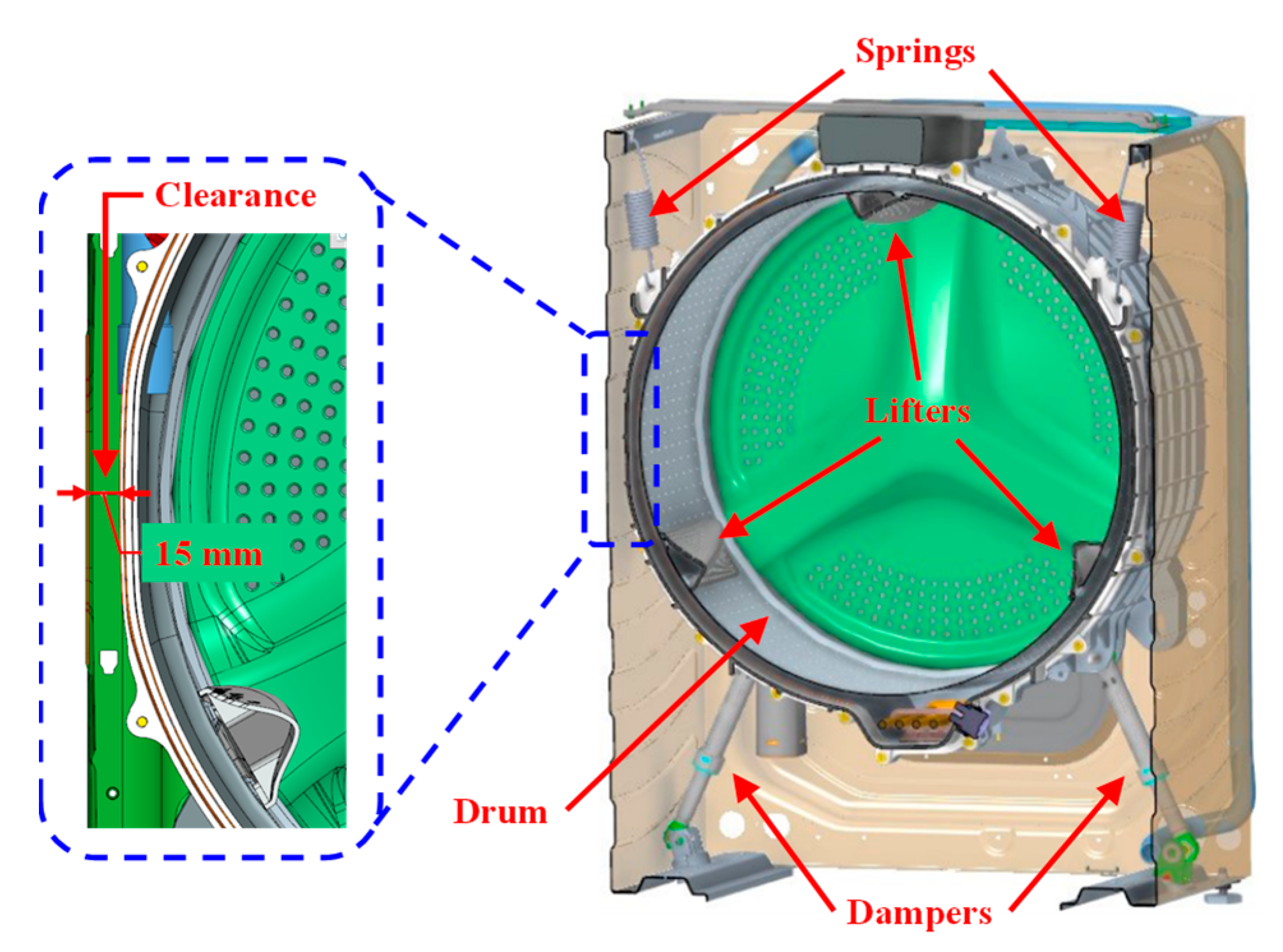
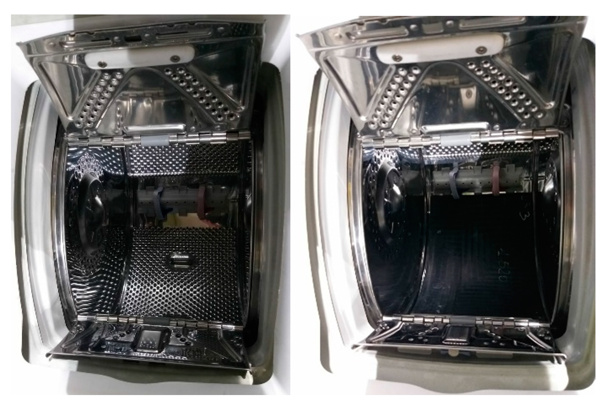
  • If the washing machine has standard lifters (Figure 1), the drum is stopped and then started again to redistribute the laundry inside the drum.
  • If the washing machine has balancing lifters, these can be filled with the right amount of water to compensate for the laundry unbalance, getting the same results of a redistribution action but without stopping the drum.
Based on all considerations presented above, the estimation of the laundry unbalance and laundry inertia is fundamental in washing machine applications.
The literature contains very few papers dealing with the estimation of inertia and load unbalance for washing machines, since the washer manufacturers prefer the patents.
Therefore, this paper proposes a novel method for estimating the laundry unbalance and the laundry inertia of a washing machine. Compared to the conventional approach usually implemented in practice, the proposed methodology has the following advantages and contributions:
(1)
The laundry inertia is evaluated at a constant average drum speed, avoiding the risks of washer damaging caused by performing an acceleration ramp.
(2)
The proposed approach does not use any lookup table (LUT), avoiding demanding off-line tuning procedures by the washer manufacturer.
(3)
The laundry inertia estimation method does not require evaluating the friction losses and the load torque generated by the laundry unbalance.
(4)
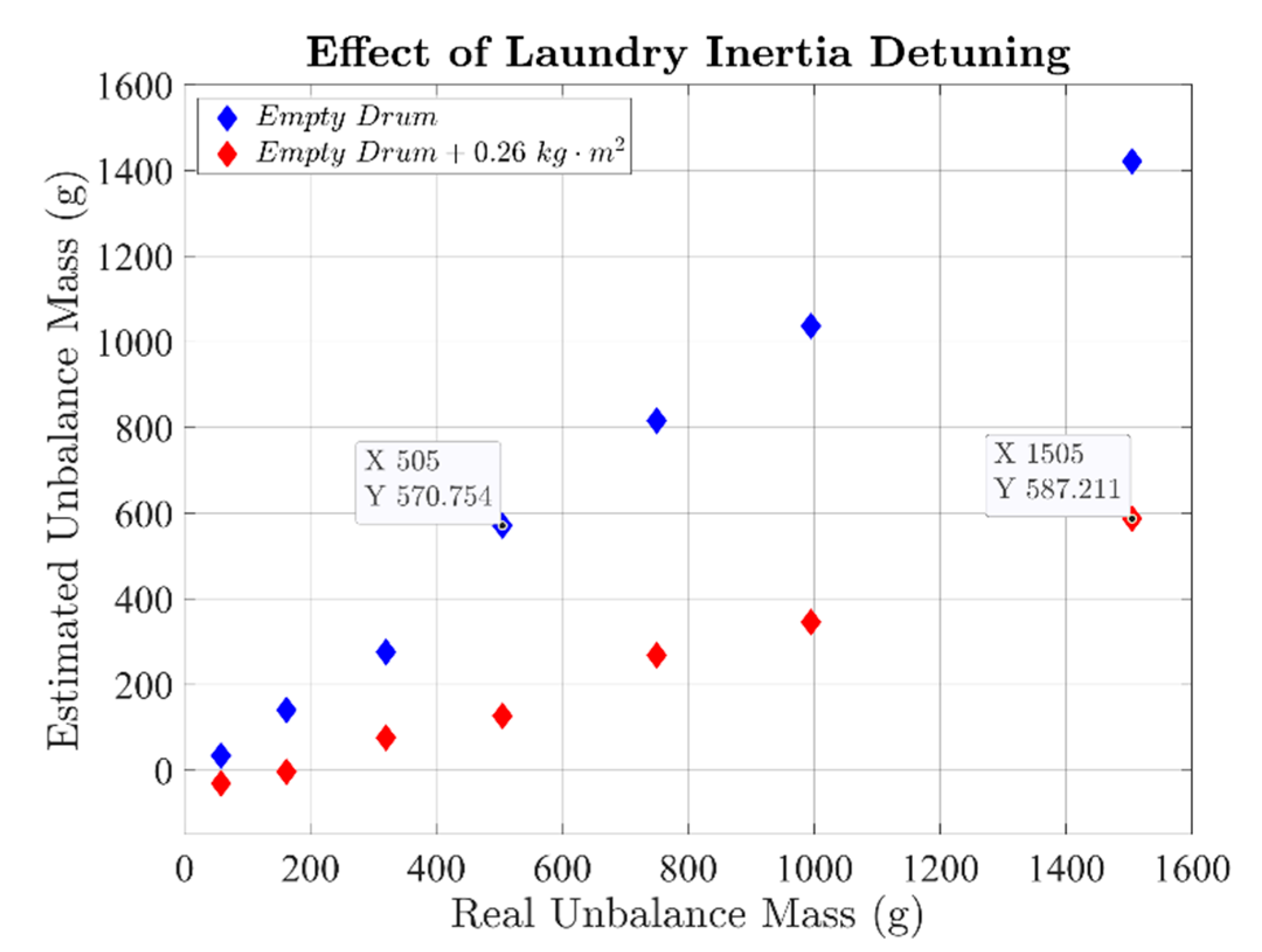
Neither the speed controller bandwidth nor the laundry inertia affect the accuracy of the laundry unbalance estimation.
(5)
The proposed methodology can be easily embedded in the already implemented eDrive control algorithm, using the microcontrollers that are usually employed for such applications.
The paper is organized as follows. Section 2 describes the model of the laundry unbalances and the effects of the latter on the drum speed. Section 3 presents in detail the conventional method for estimating the laundry unbalance and laundry inertia, describing the shortcomings of this approach. The proposed method’s description is reported in Section 4, highlighting the introduced advantages and the added value. The validation of the proposed solution through simulation and experiments is reported in Section 5, while Section 6 provides the paper conclusions.

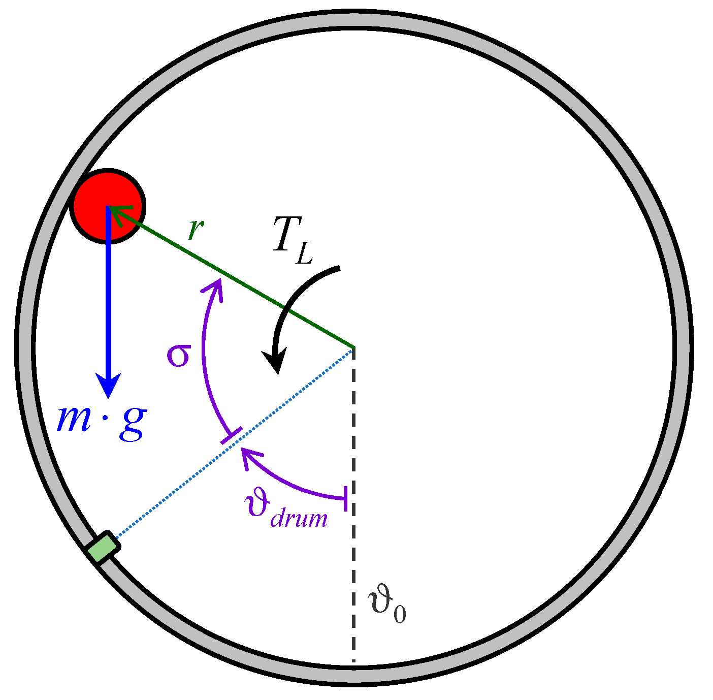
2. Model of the Laundry Unbalance

In the following, the model of the laundry unbalance for a horizontal-axis washing machine is reported. This model is valid for a drum speed higher than the satelization speed. The latter is defined as the speed value above which the laundry distributes itself inside the drum without moving. If the speed is higher than the satelization threshold, the laundry does not tumble anymore because it is sticked on the internal surface of the drum.
For commercial washing machines, the satelization speed is usually close to 100 rpm. In this condition, the amount of laundry inside the drum can be divided into two parts:
(1)
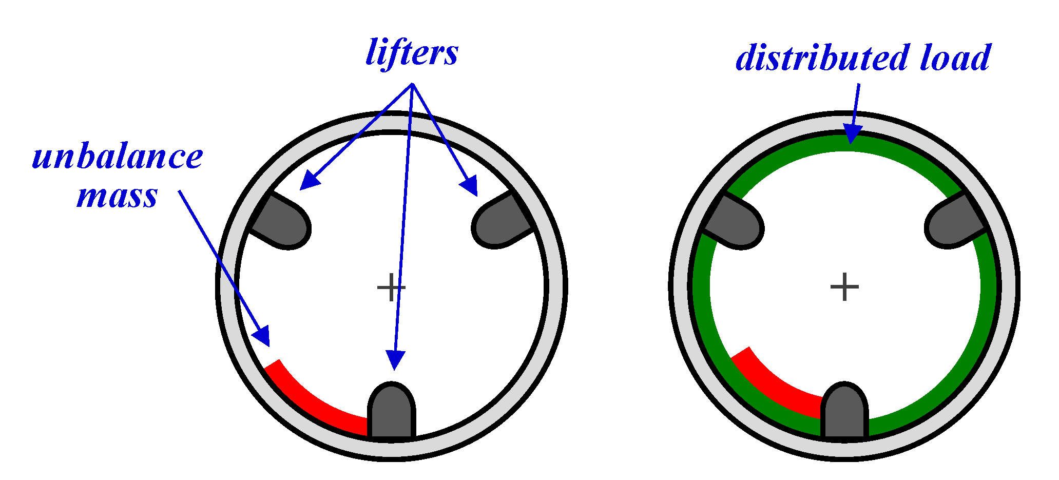
Distributed load—Consisting of the laundry portion that is uniformly distributed inside the drum.
(2)
Unbalance mass—Consisting of the laundry portion that, on the contrary, is not uniformly distributed inside the drum.
Based on the literature [11], the laundry unbalance can be modeled as a mass point m attached to the drum’s internal surface, as shown in Figure 4. According to such a model, the unbalance mass leads to a load torque TL computed as:
T L = m g r sin ( ϑ d r u m + σ )
where g is the gravitational acceleration (≈9.81 m/s2), r is the drum radius, ϑdrum is the drum’s angular position to the vertical axis, and σ is the angular displacement of the unbalance mass to the drum position.
When the drum speed is higher than the satelization speed, the angular displacement σ between the unbalance mass and the drum position is constant. Therefore, based on (1), the unbalanced mass leads to a sinusoidal load torque TL whose period is one mechanical revolution of the drum. The peak value of TL depends on the unbalanced mass m.
For example, if considering an unbalance mass of m = 1 kg, and a drum radius of r = 0.2 m, a sinusoidal load torque with a peak of about 1.96 Nm ensues.
Since the load torque acts as an additive disturbance on the motor’s speed control, a ripple in the drum speed is generated. Besides, the ripple amplitude depends on the speed loop bandwidth. Usually, the speed control loop is implemented with a conventional proportional-integral (PI) regulator whose setting is crucial in keeping the drum speed oscillations within acceptable limits. As described better in the next sections, the drum speed oscillations should not be eliminated, as they are used to estimate the laundry unbalance.

3. Conventional Method for Estimating the Laundry Unbalance and Laundry Inertia

The literature and patent database report several methods for estimating the laundry inertia [12,13,14], the laundry unbalance [11,15,16,17,18,19,20,21,22], or both [23].
These techniques aim at finding a correlation between the ripple of the drum speed and the laundry unbalance that causes it, as described in Section 2. However, to get an accurate estimation of the laundry unbalance, the above correlation must consider the damping effect of the laundry inertia on the drum speed’s oscillations. Consequently, the accurate estimation of the laundry unbalance also requires the assessment of the laundry inertia. The industry’s conventional method uses an “acceleration ramp” for the simultaneous estimation of the laundry unbalance and laundry inertia. The procedure is performed before the spinning phase to understand if the unbalance mass leads to excessive mechanical stress both when the resonance region is crossed and at the final spin speed (risk of bending torque on the washer bearings).

3.1. Conventional Method Speed Profile
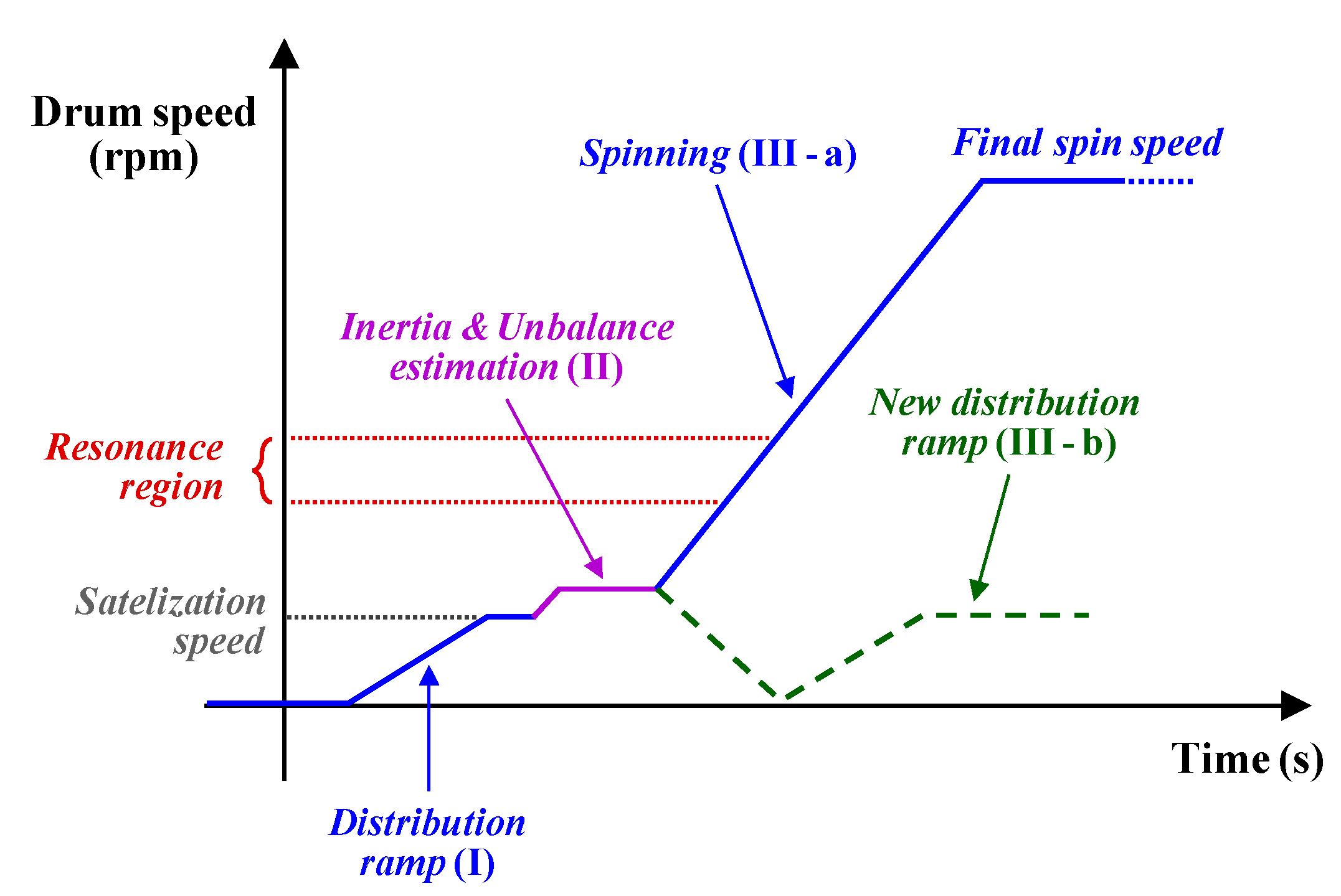
The profile of the drum speed for the conventional method is shown in Figure 5. The following actions are performed
(I)
Distribution ramp—The speed drum is set to the satelization value, allowing for the laundry’s distribution inside the drum.
(II)
Acceleration ramp—The drum is accelerated with a constant average torque using the motor control scheme, allowing for the estimation of laundry inertia.
(III)
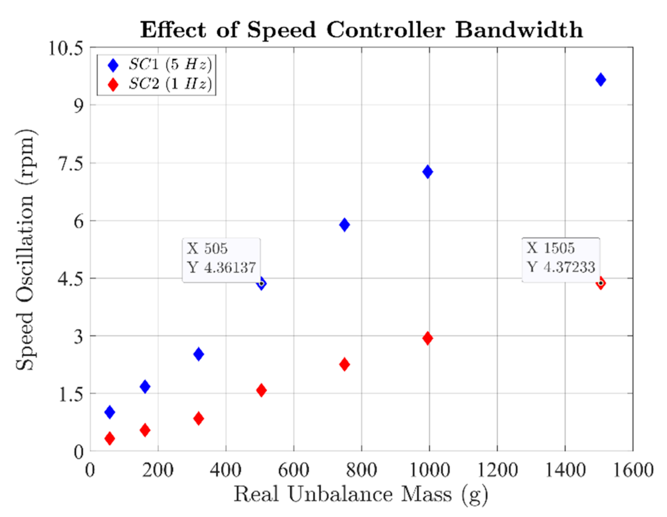
Unbalance estimation—According to the speed controller settings, the oscillations of the drum speed are used to estimate the unbalance mass.
(IV)
Decision making—Based on the estimated unbalance mass, two options are possible. If this value is below the maximum limit, (a) the spinning process is started, completing the washing cycle. Conversely, if the estimated unbalance mass overcomes the safety limit, (b) the drum is stopped, and a new distribution ramp is started, thus repeating the whole sequence.
The acceleration ramp is usually performed in the speed range between the satelization threshold and the resonance region, i.e., typically 100 to 300 rpm, depending on the considered washer. The standard way to evaluate the motor’s net torque is to estimate the electromagnetic torque Tem first, followed by the compensation of the friction losses, Tf.
Therefore, the average motor’s net torque, Tavg, during the acceleration ramp is computed as:
T ˜ a v g = 1 n k = 1 n [ T ˜ e m ( k ) T ˜ f ( k ) ]
The superscript ~ denotes an estimated variable, while k is the generic sampling time instant of the motor control algorithm, the latter being implemented on a microcontroller. Finally, n is the overall number of samples acquired during the acceleration ramp. This number must correspond to an integer number of drum revolutions. In this way, according to (1), the load torque generated by the unbalance mass TL has an average value close to zero. Therefore, for a given motor acceleration ω ˙ * , whose value is imposed by the motor control algorithm, the overall inertia Jt is estimated as:
J ˜ t = T ˜ a v g / ω ˙ *
For a direct drive washing machine, the overall inertia directly corresponds to that of the drum plus laundry. Conversely, for a belt-driven washing machine, the belt ratio must be considered.
Compared to the laundry inertia estimation, the evaluation of the laundry unbalance is performed using pre-loaded LUTs. Indeed, the washer manufacturers usually perform demanding identification procedures that correlate the laundry unbalance to the speed controller’s bandwidth and the amplitude of the drum speed oscillations caused by the unbalance mass. Such identification procedures are performed off-line on a dedicated test rig in the laboratory, where the value of the unbalance mass is known as rubber plates are used (see Figure 2). Once all possible values of the unbalance mass have been mapped and the speed controller bandwidth has been chosen, a specific LUT is uploaded in the washer control algorithm.
In summary, after the acceleration ramp (II), the unbalance mass estimation (III) at constant average speed is performed (see Figure 5). The estimated overall inertia J ˜ t is first used to tune the speed controller bandwidth at the target value. Finally, according to the measured speed oscillations, the unbalance mass is computed using the pre-loaded LUT, allowing for the decision making (IV).

3.2. Conventional Method’s Critical Points

Although the conventional method is simple, it has the following critical points:
(1)
The estimation of unbalance mass requires experimental LUTs, forcing the washer manufacturer to perform demanding identification procedures that must be performed off-line using dedicated test rigs.
(2)
The laundry inertia evaluation needs to estimate friction (2), thus requiring in-depth modeling of the mechanical transmission system (motor to the drum).
(3)
The acceleration ramp may excite the drum’s mechanical resonance, running the risk of the washing unit’s oscillations exceeding the clearance (see Figure 1), touching the cabinet, and damaging the washer.
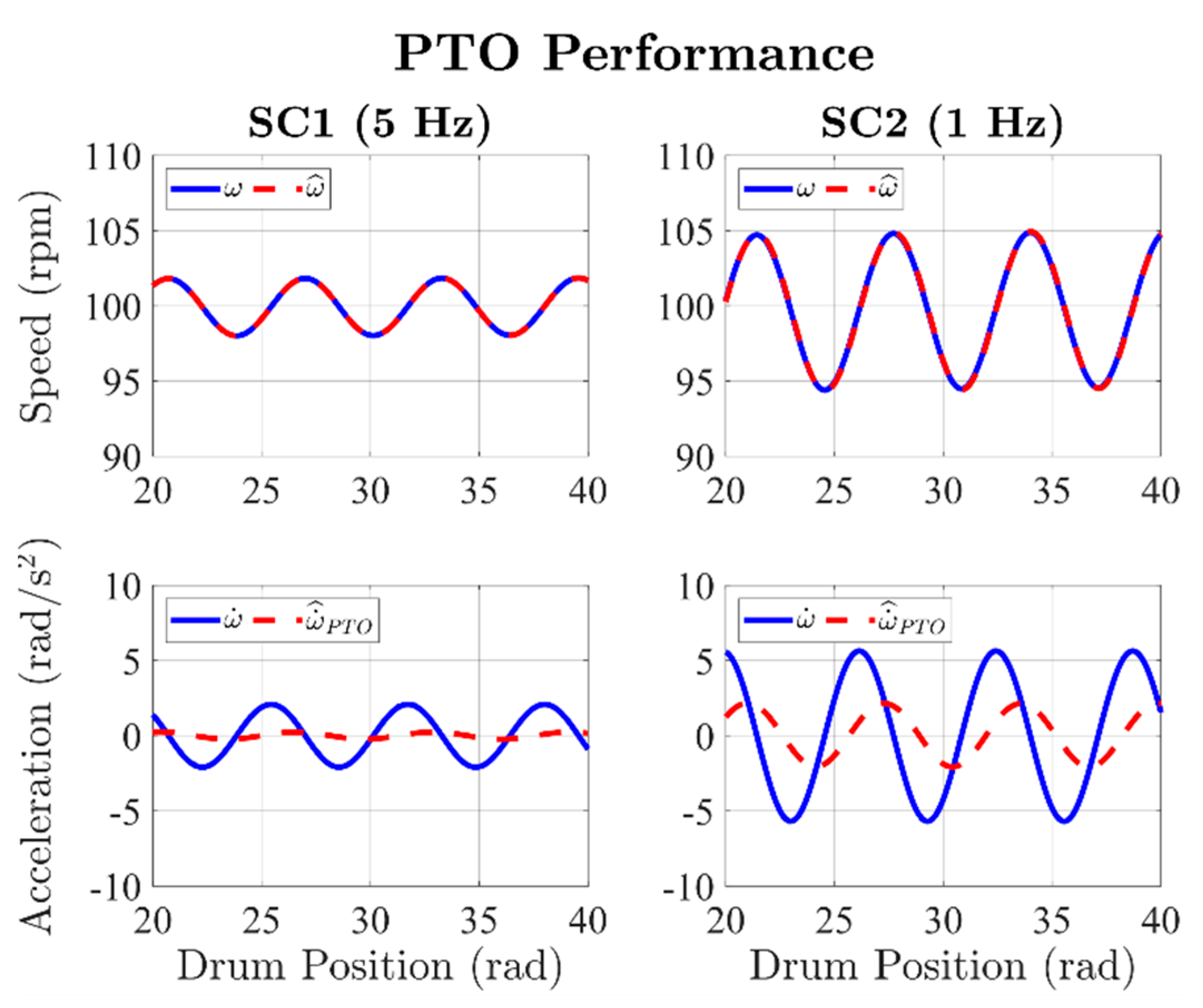
To demonstrate the importance of getting an accurate LUT to estimate the unbalance mass using the conventional method, experimental tests have been carried out on a commercial direct-drive washer. The first test, whose results are shown in Figure 6, demonstrates how the speed controller bandwidth must be tuned accurately. Two cases of study have been considered:
Speed controller bandwidth of 5 Hz; such a setting is from now onwards denoted as SC1.
Speed controller bandwidth of 1 Hz; by analogy, this setting is denoted as SC2.
It is noted how, depending on the value of the speed controller bandwidth, the same speed oscillation can be caused by two completely different unbalance mass values. For example, referring to Figure 6, a speed oscillation of 4.3 rpm is caused by an unbalance mass of 500 g for SC1. However, the same speed oscillation is caused by an unbalance mass of 1500 g if SC2 is set. Therefore, to consider the amplitude of the speed oscillations, a reliable variable for estimating the unbalance mass, the speed controller bandwidth must be tuned accurately. In other words, an accurate estimation of the overall inertia Jt is needed to set the speed controller parameters properly.
The sensitivity of the conventional method to the laundry inertia detuning is demonstrated by the results shown in Figure 7. In the case of the empty drum, corresponding to the presence of only the unbalance mass inside it (as in Figure 2, left), the conventional method algorithm estimates the unbalance mass correctly, regardless of its value. For example, to a real unbalance mass of 505 g, the conventional method leads to an estimate of 570.8 g, corresponding to an error of about 13%, resulting in an acceptable value.
However, in the case of a laundry inertia detuning of 0.26 kg∙m2, e.g., caused by a distributed load (as in Figure 2, right), the conventional method strongly underestimates the unbalance mass. For example, to a real unbalance mass of 1505 g, the conventional method algorithm estimates a value of only 587.2 g, corresponding to an unacceptable error of about 61%. Therefore, the laundry inertia estimation is of primary importance to update the LUT and properly evaluate the unbalance mass. Furthermore, this is a typical case in which the real unbalance mass damages the washer if the spinning is performed (IV-A), as the washing unit’s oscillations exceed the mechanical clearance (see Figure 3).
Finally, the most delicate aspect of the conventional method consists in the speed range in which the acceleration ramp should be performed. Indeed, to get an accurate estimation of the laundry inertia, such a range must be as broad as possible. However, below the satelization speed, the laundry does not distribute itself inside the drum.
Therefore, the only way to extend the speed range is to increase the acceleration ramp’s high-speed limit, setting it close to or inside the resonance region (as shown in Figure 5). Such a solution often happens in practice, since the speed range between the satelization speed and the low-limit of the resonance region is often small due to the washers’ mechanical design. Therefore, the acceleration ramp’s execution in this speed range is usually not enough, hindering the laundry inertia’s evaluation with acceptable accuracy. That results in forcing the extension of the acceleration ramp within the resonance region (see Figure 5). However, if such a solution is applied, two cases can happen, as follows:
(1)
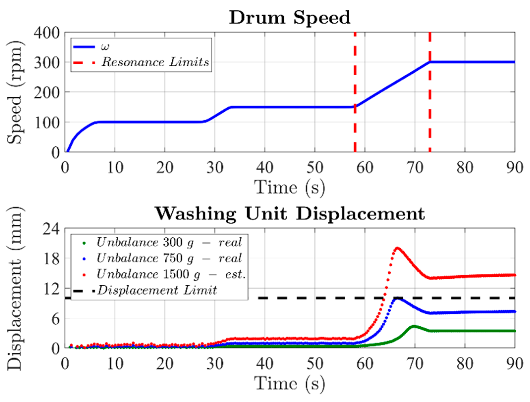
The unbalance mass has a small value; therefore, the washer resonances excitation does not lead to dangerous oscillations of the washing unit, allowing the execution of the acceleration ramp without running any risk.
(2)
The unknown unbalance mass has a high value; the washer resonances excitation leads to the washing unit oscillations whose amplitude exceeds the clearance and may damage the washer (see Figure 3).
In both cases, the unbalance mass is unknown, since it is evaluated only after estimating the laundry inertia, i.e., the acceleration ramp’s execution. Therefore, the conventional method statistically leads the washing unit to touch the cabinet, with negative consequences related to the washer’s mechanical damaging and noise.

3.3. Conventional Method Literature

The literature does not report many publications in this research field, since the washer manufacturers prefer to file patents, protecting their interests. However, the conventional method is still the most employed solution, eventually proposed under different variants. For example, the solutions in [15,17] propose the estimation of the unbalance mass using the motor torque ripple instead of the speed oscillations. However, these methods require a high bandwidth of the speed controller to keep the speed constant, without any oscillation. Unfortunately, this solution is usually not viable, since the motor control algorithms for washing machines are sensorless, minimizing costs but being unable to get a high-performance speed control. An alternative solution is found in [12], which proposes the laundry inertia’s estimation using the power instead of the torque. Such an approach is useful for those applications where the torque estimation is not available. Finally, another industry solution consists of estimating the unbalance mass before and after performing the acceleration ramp. In this way, the first estimate is obtained at a low drum speed, allowing for a better detection of its oscillations. Conversely, the second estimate is used to compensate for the error of the first one, using the just estimated value of laundry inertia obtained by performing the acceleration ramp.

4. Proposed Method for Estimating the Laundry Unbalance and Laundry Inertia

Compared to the conventional method, the proposed one estimates the laundry inertia and the laundry unbalance at a constant average drum speed, using the already implemented motor control scheme. The following conditions are necessary:
  • The drum speed must be higher or at least equal to the satelization threshold, avoiding any movement of the laundry inside the drum.
  • The drum speed must be significantly lower than the resonance speed, avoiding any mechanical interference.
For the proposed method, the test speed is usually set to 100 rpm. Considering the dynamic properties of the standard washing machines, this value guarantees the laundry satelization and, at the same time, a consistent speed margin from the resonance region. The objectives of the proposed method are:
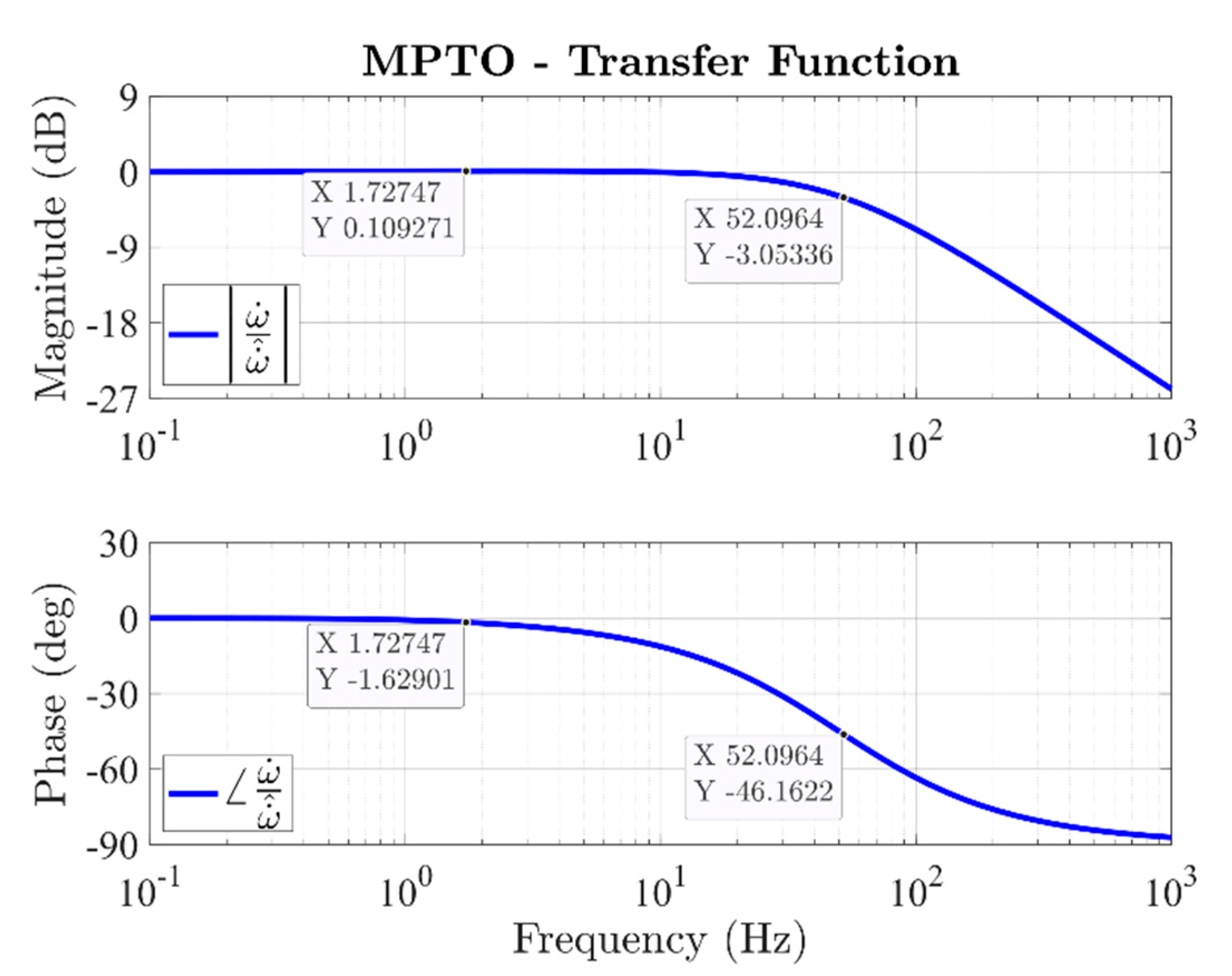
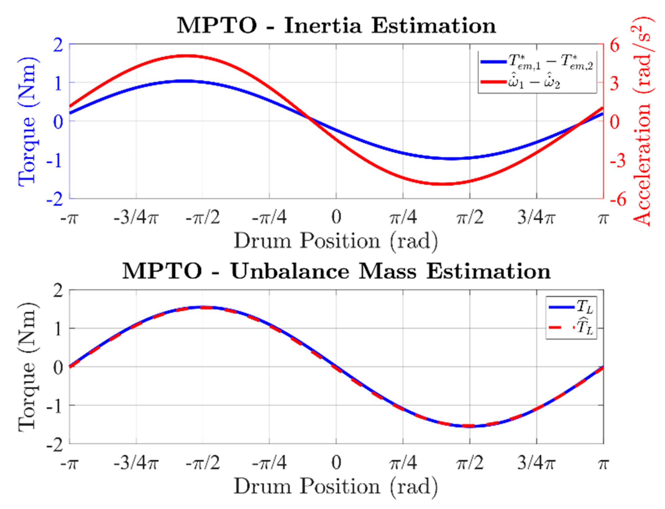
  • Accurate estimation of the drum acceleration due to the speed oscillations
  • Accurate estimation of the load torque that is oscillating for the considered application (washers)
Such quantities cannot be estimated simultaneously using a conventional phase-locked loop (PLL). Therefore, the existing motor control algorithm is enhanced with a position-tracking observer (PTO) [24,25], which is a well-known solution in the literature, especially for industrial applications.
The literature reports some application examples of PTO or similar solutions for washers. In [26,27], the observed motor position is used for compensating the bumps generated by low-resolution Hall effect sensors. Such transducers are often used to implement sensor-based motor control schemes, but keeping the washer’s manufacturing cost low. However, it is pointed out how most of the current eDrives for washing machines are sensorless, thanks to the good performance reached by such control algorithms [3,4,5,6,7,8,9]. Another interesting solution is presented in [19], where a load torque observer is proposed to improve the speed controller’s performance.
The conventional PTO block diagram is shown in Figure 8. Although this structure is well consolidated, it does not allow for the accurate estimation of the angular acceleration ω ˙ ^ . Indeed, the PTO has been proposed for getting a bumpless position, a bumpless speed, or both. The PTO can also be used to estimate the load torque (see Figure 8). Besides, to avoid the potential noise of the discrete-time derivation, the output of the derivative gain kd is conventionally considered as a speed regulation. However, this simplification renders the first integrator’s input ω ˙ ^ P T O , highlighted in dark red in Figure 8, not coincident with the angular acceleration.
For this reason, the proposed method uses a modified position-tracking observer (MPTO), whose block diagram is shown in Figure 9. It is noted how the outputs of the proportional, integral, and derivative blocks are considered as contributions of the observed load torque. In this way, although the discrete-time derivation must be performed, the first integrator’s input corresponds to the angular acceleration of the drum ω ˙ . The MPTO inputs are the estimated electromagnetic motor torque Tem, assumed to be coincident with the reference one, Tem*, provided by the speed controller, and the drum position ϑdrum. The proposed MTPO uses the Euler discretization method, as this choice can guarantee a good compromise between implementation simplicity and observation accuracy.
For simplicity, a direct-drive washer is considered, avoiding the introduction of a belt ratio. Therefore, the drum position is obtained from the motor control algorithm after considering the motor pole pairs p. The design procedure of the integral gain ki is the same as the conventional PTO [28] and not reported here, since it is well known in the literature.
Concerning the proportional kpm and derivative kdm gains, these are computed starting from those of the PTO. After using the block diagrams rules, these gains are corrected to keep the equivalence between the two observers as:
{ k p m = k p + β ˜ k d k d m = J ˜ t k d
where β is the viscous friction coefficient. The MPTO can be integrated with any sensorless motor control algorithm, regardless of how the torque regulation is performed (e.g., current vector control [3,4,5,7,9], direct flux, and torque control [6]). For example, the integration of the MPTO on a sensorless field-oriented control scheme is shown in Figure 10, helping the understanding. Further details about the sensorless control algorithm are not reported, as they are beyond the scope of this work. Finally, it is noted how both PTO and MPTO consider as input electromagnetic torque the reference signal provided by the speed controller (see Figure 10). Such a simplification is valid only if the motor control algorithm limits the reference torque, allowing the torque controller to satisfy it. Otherwise, the electromagnetic torque can be estimated using the sensorless observer implemented on the motor control algorithm [6].
The profile of the drum speed for the proposed method is shown in Figure 11. Compared to the conventional method, the acceleration ramp is avoided. Three main actions are performed, as follows.
  • Distribution ramp—See the description in Section 3.
  • Inertia and Unbalance estimation—Using the MPTO, laundry inertia and laundry unbalance are estimated at a constant average drum speed.
  • Decision making—See the description in Section 3.
The main advantage of the proposed approach is evident, as the acceleration ramp is not performed. Therefore, the speed region between the satelization threshold and the resonance can be very narrow, without affecting the estimation performance. Moreover, the risk to excite the washer’s mechanical resonance before estimating the laundry unbalance is avoided. Indeed, the estimation of the laundry inertia and laundry unbalance can be performed for any speed value between the satelization threshold and the resonance region.
The proposed method estimates the laundry inertia by comparing two different system conditions, in the following indicated using the subscripts 1 and 2. According to the mechanical balance of the drum, the following equation system is derived:
{ T e m , 1 T L , 1 = J t ω ˙ 1 + β ω 1 T e m , 2 T L , 2 = J t ω ˙ 2 + β ω 2
The above system can be expressed as a function of the time or the drum position ϑdrum. If assuming the latter as the base variable, the load torque TL generated by the unbalance mass does not depend on the considered condition.
Indeed, as demonstrated in (1), the load torque depends only on the drum position ϑdrum. Concerning the friction torque Tf = β ∙ ω, it consists of two contributions. The first is related to the drum’s average speed, while the second is related to the oscillations caused by the unbalance mass. However, the second contribution can be considered negligible if compared to the first one.
In summary, if the two conditions above refer to the same average speed ωavg, (5) can be expressed as a function of the drum position as:
{ T e m , 1 T L = J t ω ˙ 1 + β ω a v g T e m , 2 T L = J t ω ˙ 2 + β ω a v g
Consequently, the overall inertia (drum plus laundry) can be obtained by comparing the two system conditions as:
J t = T e m , 1 T e m , 2 ω ˙ 1 ω ˙ 2
It is noted how using this approach, the overall inertia is computed with high accuracy, as neither the friction losses nor the load torque needs to be considered. The proposed method performs the estimation of the laundry inertia using (7).
For getting two different system conditions while keeping the same average speed, it is sufficient to set different values of the speed controller bandwidth. In this way, different drum speed oscillations are obtained, differentiating the electromagnetic torque and angular acceleration for every drum position. For example, it is possible to use settings SC1 and SC2 presented in Section 3.
The application of (7) requires evaluating the drum acceleration related to the speed oscillations caused by the unbalance mass. For this reason, the use of the MPTO (Figure 9) is proposed. However, the MPTO gains must be designed for getting a proper acceleration-tracking, thus considering the following transfer function:
ω ˙ ^ ω ˙ = k d m s 2 + k p m s + k i J ˜ t s 3 + ( k d m + β ˜ ) s 2 + k p m s + k i
where s is the Laplace variable, while the superscript ^ denotes an observed variable.
Therefore, using the MPTO, the proposed method performs the estimation of overall inertia by applying (7) as:
J ˜ t = ( T e m , 1 * T e m , 2 * ) / ( ω ˙ ^ 1 ω ˙ ^ 2 )
As stated before, the electromagnetic torque is assumed to coincide with the reference one provided by the speed controller (see Figure 10). In the alternative, the electromagnetic torque can be estimated using the eDrive variables (e.g., measured currents, observed fluxes) [6].
Finally, according to (1), the estimation of the unbalance mass m can be performed using the peak value of the observed load torque T ^ L as:
m ˜ = T ^ L , p e a k g r ˜
It is noted how the unbalance mass estimation strictly depends on the accuracy of the MPTO, thus related to the detuning of the viscous friction coefficient β. Therefore, as with the conventional method, the proposed one seems to require friction estimation. However, this operation can be performed easily, since the friction torque is computed as the average value of the electromagnetic torque over an integer number of the drum’s mechanical revolutions. Therefore, at the beginning of the proposed identification procedure, the viscous friction coefficient β is estimated as:
β ˜ = 1 n ω a v g k = 1 n T e m * ( k )
In this way, (10) is applied with a high level of confidence, leading to an accurate estimation of the laundry unbalance.
Figure 12 shows the flowchart for the proposed method.
At the beginning of the procedure, both laundry inertia Jt and viscous friction coefficient β are unknown. Therefore, the MPTO is initialized as follows:
  • J ˜ t 
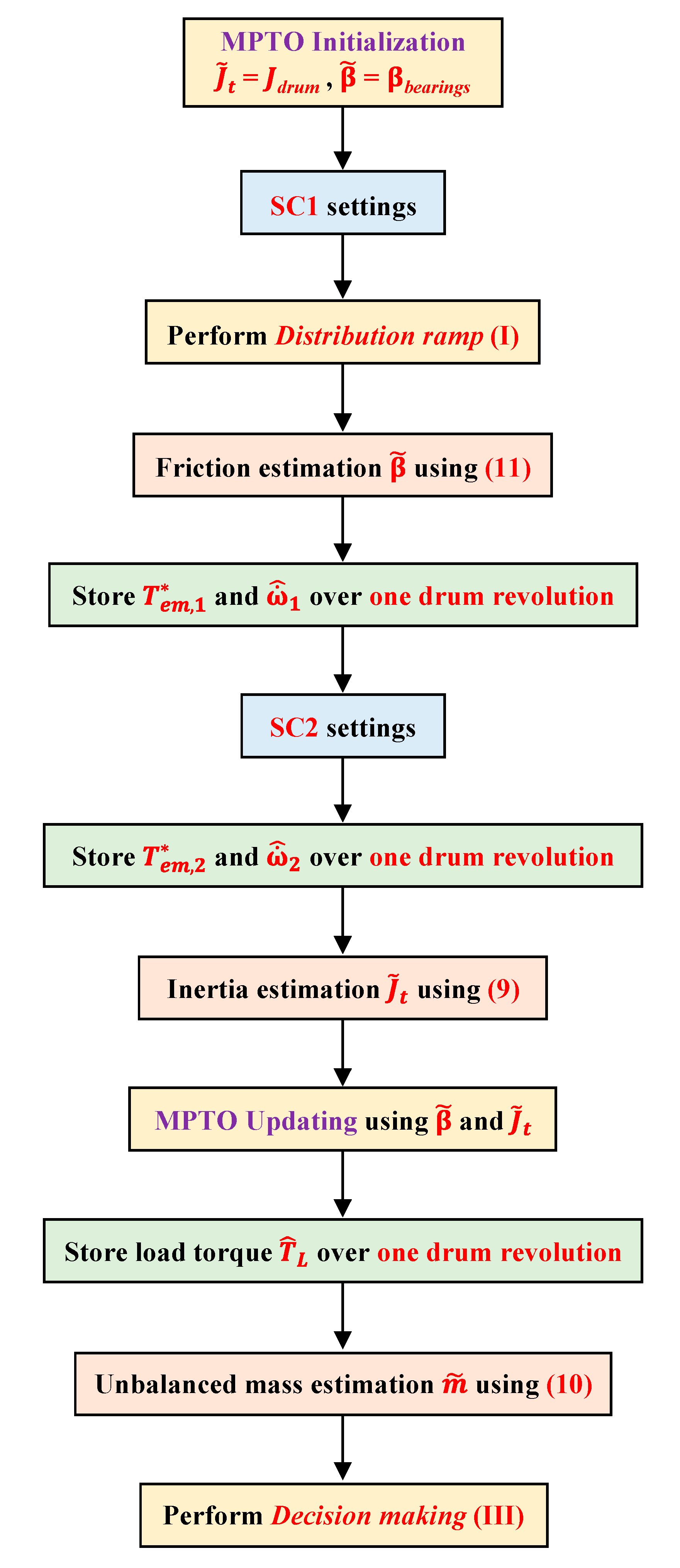
is set to the value related to the empty drum condition Jdrum
  • β ˜ is set to the value related to the bearings βbearings
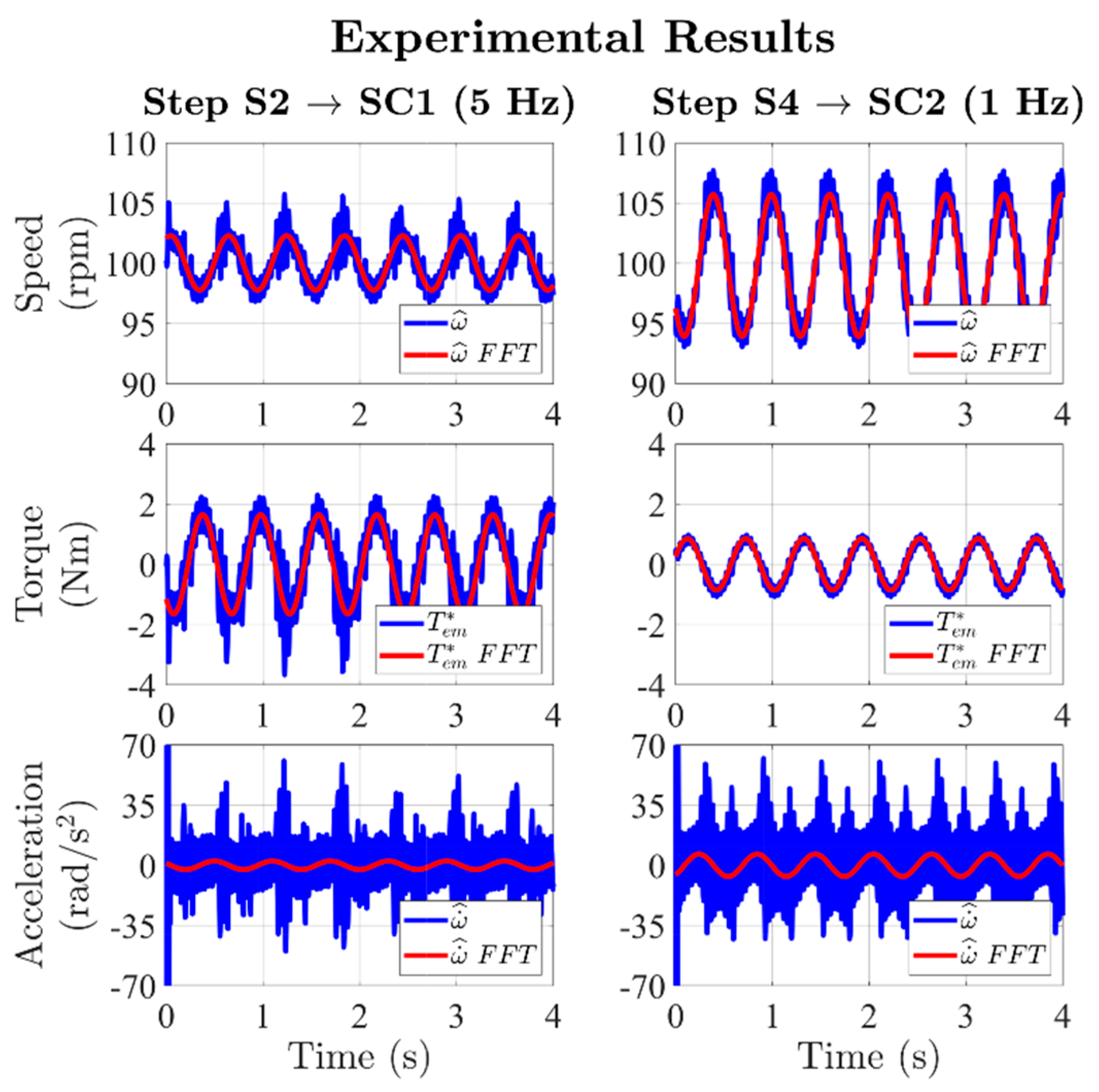
Both the above-mentioned values are known by the washer manufacturer.
According to (8), the MPTO parameters (kpm, ki, and kdm) are set to get a proper acceleration-tracking. Concerning the speed controller bandwidth, SC1 settings are initially set. After performing the distribution ramp (I), the viscous friction coefficient β is estimated using (11). The values of the reference electromagnetic torque T e m , 1 * and drum acceleration ω ˙ ^ 1 are stored over one drum revolution. Subsequently, by keeping the drum average speed constant, SC2 settings are set, thus storing the values of reference electromagnetic torque T e m , 2 * and drum acceleration ω ˙ ^ 2 also in this case for one drum revolution. In this way, the overall inertia J ˜ t (laundry plus drum) is computed using (9). The MPTO is thus tuned correctly using the obtained values of overall inertia J ˜ t and viscous friction coefficient β ˜ , thereby allowing the estimation of the load torque TL with high accuracy.
Finally, the observed value of load torque T ^ L is stored over one drum revolution, allowing the computation of the unbalanced mass m ˜ using (10). The estimated value of unbalance mass is thus used for performing decision making (III).

5. Validation

The validation of the proposed methodology has been carried out through simulation and experimental tests on a commercial direct-drive horizontal-axis washing machine. The simulation results are illustrated first to facilitate the understanding of the experimental validation.

5.1. Simulation Results
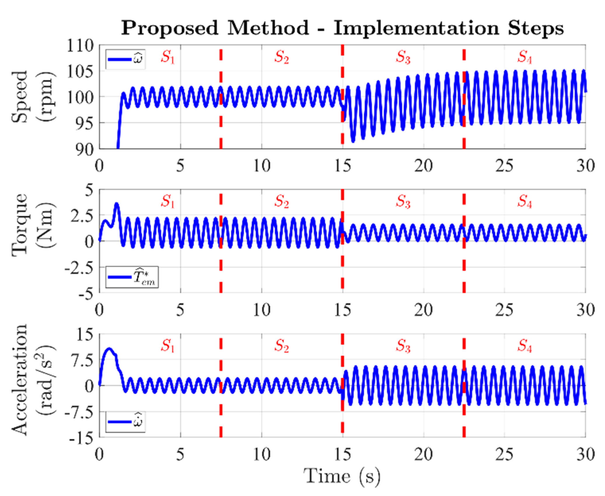
The proposed methodology has been simulated in a Matlab/Simulink environment. The primary test conditions are reported in Table 1, listing the MPTO settings used next for the experimental validation. The MPTO gains have been designed to get an acceleration-tracking bandwidth of about 50 Hz (magnitude of about −3 dB). The Bode plot of the obtained transfer function (8) is shown in Figure 13. For an average drum speed of 100 rpm, the drum acceleration oscillations frequency is about 1.67 Hz, so that the MPTO can track it with high accuracy. Indeed, for such an oscillation frequency, the magnitude and phase shift of (8) are about 0.109 dB (1.26%) and −1.63 deg, respectively. Finally, the two system conditions for estimating the inertia (9) are SC1 and SC2, corresponding to a speed controller bandwidth of 5 Hz and 1 Hz, respectively.
The better performance of the MPTO with regard to the PTO is demonstrated in Figure 14 and Figure 15. It is noted how, in terms of speed-tracking, the observation performance of PTO and MPTO is the same. However, if comparing the acceleration-tracking performance, it is evident that the PTO is characterized by a significant error in amplitude and phase shift, making such an observer unsuitable for the purposes of this work. Conversely, the MPTO can track the drum acceleration with high accuracy, thus justifying its application in the proposed method.
Referring to Figure 14 and Figure 15, the acceleration is expressed as a function of the drum position for applying (9) correctly. Indeed, during the proposed identification procedure, the reference electromagnetic torque, drum speed, and drum acceleration follow the time profile shown in Figure 16.
It is noted how the proposed method is structured in four implementation steps (S1, S2, S3, S4), as follows.
S1
The distribution ramp is performed (see Figure 11), setting the speed controller as SC1 and imposing the average target speed ωavg, i.e., 100 rpm, to the considered case (see Figure 16).
S2
The viscous friction coefficient β using (11) is estimated, allowing the calibration of the MPTO. Finally, the profiles of the electromagnetic torque T e m , 1 * and observed drum acceleration ω ˙ ^ 1 , over one drum revolution, are stored.
S3
The speed controller is set as SC2, and a reasonable waiting time is used to reach steady-state operation.
S4
The new profiles of the electromagnetic torque T e m , 2 * and observed drum acceleration ω ˙ ^ 2 , over one drum revolution, are stored. The overall inertia Jt is evaluated using (9), allowing for the full calibration of the MPTO. Finally, the observed load torque profile T ^ L over one drum revolution is stored, leading to the estimation of the unbalance mass m using (10).
For the considered simulation test, the numerator (electromagnetic torque difference between SC1 and SC2) and denominator (drum acceleration difference between SC1 and SC2) of (9) are shown on the top of Figure 17. At the bottom of the same figure, the observed load torque profile at the procedure end is shown. It is noted how (9) can be computed for every drum position, apart from the cases in which the numerator and denominator get zero. For this reason, it is preferable to compute the inertia as the average of (9) over the drum revolution, getting a robust result. In summary, the computed values of inertia Jt (9) and unbalance mass m (10) at the simulation end are J ˜ t = 0.205 kg∙m2 and m ˜ = 0.744 kg.
Compared to the values reported in Table 1, the absolute errors of inertia and unbalance mass are 2.5% and 0.8%, respectively, showing excellent accuracy.

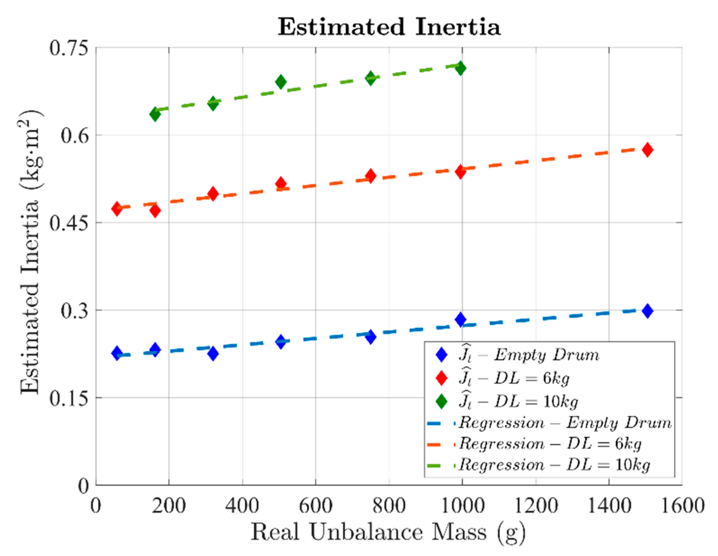
5.2. Experimental Results

The experimental validation has been carried out on a commercial direct-drive horizontal-axis washer (see Figure 18). The unbalance mass and the distributed load have been emulated using dedicated rubber plates placed inside the drum (see Figure 2 and Figure 18). The already implemented sensorless motor control algorithm of the washer has been enhanced with the MPTO, whose parameters are the same that have been used for the simulation validation (Table 1). In addition, the two system conditions used for estimating the inertia (9) are still SC1 and SC2. Finally, the estimation of the laundry inertia and laundry unbalance has been performed at a constant average drum speed of 100 rpm.
The washer motor is 36 poles, fractional slot permanent magnet machine, rated 600 W with a maximum speed of 1200 rpm. Since a direct-drive washer is considered, the maximum motor speed also corresponds to the spinning limit.
The experimental verification has been performed by testing different values of distributed load (DL), as follows.
(1)
0 kg DL, corresponding to the empty drum condition (Jdrum = 0.22 kg∙m2).
(2)
6 kg DL, emulating a laundry inertia of Jl = 0.26 kg∙m2.
(3)
10 kg DL, emulating a laundry inertia of Jl = 0.46 kg∙m2.
Each of the conditions above has been tested with several unbalance masses, thus emulating the laundry unbalance. Seven rubber plates have been used, corresponding to the following unbalance mass m values: 58 g, 162 g, 320 g, 505 g, 750 g, 995 g, and 1505 g.
The experimental time profiles of reference electromagnetic torque, drum speed, and drum acceleration for an unbalanced mass of 750 g are shown in Figure 19, thus performing a fair comparison with the simulation test presented previously (see Figure 15 and Figure 16). It is noted how the experimental waveforms are affected by noise, as it often happens in real applications.
For this reason, the practical implementation of the proposed approach requires a fast Fourier transform (FFT) to get the time-fundamental component of the waveforms (see Figure 19). However, the floating-point microcontrollers used nowadays for washers support the FFT function without issues. The recommended sampling frequency for performing an accurate FFT is 100 times the time-fundamental target frequency. For example, to an average drum speed of 100 rpm, corresponding to a drum acceleration oscillations frequency of 1.67 Hz, the recommended sampling frequency is 167 Hz. Therefore, if the motor control algorithm is performed at a sampling frequency of 16 kHz, a downsampling factor equal to 10 must be applied. Moreover, the FFT algorithm does not need to be performed in real-time, resulting as not critical in terms of execution time.
The values of estimated unbalance mass for each testing condition are shown in Figure 20, performing a comparison with the conventional method results. The latter have been obtained using the LUT defined for the empty drum regardless of the DL value. It is noted how the proposed methodology estimates the unbalance mass correctly for all DL values, without using any LUT since the MTPO is implemented. Conversely, the conventional approach performs a non-negligible error as the DL increases, failing to estimate the unbalance mass, thus requiring a demanding case-by-case LUT calibration.
The performance of the proposed method in estimating the overall inertia is shown in Figure 21. It is noted how the inertia is also estimated correctly for all testing conditions. Indeed, by performing a linear regression for all DL cases, the estimated overall inertia can be expressed as a function of the estimated unbalance mass as:
J ˜ t = k 0 + k 1 m ˜
The computed regression coefficients are reported in Table 2. Regardless of the considered DL, the inertia increment for each additional grams of unbalance mass is about 0.1 g∙m2 (coefficient k1). Concerning the regressor coefficient k0, it represents the inertia value related to the drum plus DL. For 0 kg DL, k0 corresponds to the drum inertia, i.e., J ˜ drum = 0.22 kg∙m2. Therefore, the DL inertia Jl is estimated as:
J ˜ l = k 0 J ˜ d r u m
By applying (13), the following values of DL inertia are estimated:
DL 6 k g J ˜ l = 0.25 k g m 2 DL 10 k g J ˜ l = 0.41 k g m 2
Compared to the real values, the estimation accuracy is good and with acceptable errors. Indeed, the DL inertia’s absolute error is 3.8% for 6 kg DL, and 10.9% for 10 kg DL. In summary, compared to the conventional method, the proposed approach exhibits high estimation performance of the laundry inertia and laundry unbalance in a wide range of washer operating conditions.

6. Conclusions

This industrial paper proposed a novel method for evaluating the laundry inertia and the laundry unbalance of a washing machine. The proposed approach is eDrive-based, since it uses the washer’s already implemented motor control algorithm, enhanced by a modified position-tracking observer.
Compared to the state-of-art in this research field, the proposed test procedure is performed at a constant average drum speed, avoiding the execution of an acceleration ramp and running the risk of damaging the washer. Furthermore, the laundry unbalance estimation is performed without using any lookup table, avoiding demanding tuning procedures by the washer manufacturer.
The proposed approach has been validated on a commercial horizontal-axis direct-drive washer using a sensorless motor control scheme. Experimental results for different conditions of laundry unbalance and laundry inertia have been provided, demonstrating the high estimation performance of the proposed procedure. The method presented in this paper is currently patent-pending.

Author Contributions

Conceptualization, D.M. and R.B.; methodology, D.M.; software, D.M.; validation, D.M.; formal analysis, S.R.; investigation, S.R.; resources, R.B.; data curation, S.R.; writing—original draft preparation, S.R.; writing—review and editing, S.R.; visualization, R.B.; supervision, R.B.; project administration, R.B.; funding acquisition, R.B. All authors have read and agreed to the published version of the manuscript.

Funding

This research was funded by the Power Electronics Innovation Center (PEIC) of Politecnico di Torino with the support of Haier Deutschland GmbH.

Conflicts of Interest

The authors declare no conflict of interest.

References

  1. Commission Delegated Regulation (EU) 2019/2014 of 11 March 2019 Supplementing Regulation (EU) 2017/1369 of the European Parliament and of the Council with Regard to Energy Labelling of Household Washing Machines and Household Washer-Dryers and Repealing Commission Delegated Regulation (EU) No 1061/2010 and Commission Directive 96/60/EC (Text with EEA Relevance), Vol. 315. 2019. Available online: https://eur-lex.europa.eu/legal-content/EN/TXT/?qid=1575536811417&uri=CELEX:32019R2014 (accessed on 15 September 2020).
  2. Commission Regulation (EU) 2019/2023 of 1 October 2019 Laying down Ecodesign Requirements for Household Washing Machines and Household Washer-Dryers Pursuant to Directive 2009/125/EC of the European Parliament and of the Council, Amending Commission Regulation (EC) No 1275/2008 and Repealing Commission Regulation (EU) No 1015/2010 (Text with EEA Relevance), Vol. 315. 2019. Available online: https://eur-lex.europa.eu/legal-content/EN/TXT/?toc=OJ%3AL%3A2019%3A315%3ATOC&uri=uriserv%3AOJ.L_.2019.315.01.0285.01.ENG (accessed on 15 September 2020).
  3. Liu, T.-H.; Lin, C.-K.; Lo, C.-H. Implementation of a novel high-performance sensorless IPMSM drive for washing machines. In Proceedings of the 2010 IEEE International Conference on Industrial Technology, Vina del Mar, Chile, 14–17 March 2010; pp. 367–372. [Google Scholar] [CrossRef]
  4. Cho, K.Y.; Yang, S.B.; Hong, C.H. Sensorless control of a PM synchronous motor for direct drive washer without rotor position sensors. IEE Proc. Electr. Power Appl. 2014, 151, 61–69. [Google Scholar] [CrossRef]
  5. Zhang, Z.; Xu, H.; Xu, L.; Heilman, L.E. Sensorless direct field-oriented control of three-phase induction motors based on “Sliding Mode” for washing-machine drive applications. IEEE Trans. Ind. Appl. 2006, 42, 694–701. [Google Scholar] [CrossRef]
  6. Bojoi, R.; He, B.; Rosa, F.; Pegoraro, F. Sensorless Direct Flux and Torque Control for Direct Drive washing machine applications. In Proceedings of the 2011 IEEE Energy Conversion Congress and Exposition, Phoenix, AZ, USA, 17–22 September 2011; pp. 347–354. [Google Scholar] [CrossRef]
  7. Balazovic, P.; Filka, R. Sensorless PMSM control for H-axis washing machine drive. In Proceedings of the 2008 IEEE Power Electronics Specialists Conference, Rhodes, Greece, 15–19 June 2008; pp. 4237–4242. [Google Scholar] [CrossRef]
  8. Dianov, A.; Kim, N.S.; Lim, S.M. Sensorless starting of horizontal axis washing machines with direct drive. In Proceedings of the 2013 International Conference on Electrical Machines and Systems (ICEMS), Busan, Korea, 26–29 October 2013; pp. 1–6. [Google Scholar] [CrossRef]
  9. Chi, S.; Zhang, Z.; Xu, L. Sliding-Mode Sensorless Control of Direct-Drive PM Synchronous Motors for Washing Machine Applications. IEEE Trans. Ind. Appl. 2009, 45, 582–590. [Google Scholar] [CrossRef]
  10. Washing Machine. Wikipedia. 13 September 2020. Available online: https://en.wikipedia.org/w/index.php?title=Washing_machine&oldid=978198687 (accessed on 15 September 2020).
  11. Kim, H. On-line mechanical unbalance estimation for permanent magnet synchronous machine drives. IET Electr. Power Appl. 2009, 3, 178–186. [Google Scholar] [CrossRef]
  12. Suel, I.R.D. Washing Machine Appliance and Method for Calculating a Load Size of Articles. U.S. Patent 9206538B2, 8 December 2015. [Google Scholar]
  13. Lee, J.-H.; Hwang, C.-H.; Kim, K.-M.; Lee, W.; Won, W.-C.; Won, C.-Y.; Kim, Y.-R. Optimal washing time control algorithm for the drum washing machine using an inertia estimator. In Proceedings of the 2008 IEEE 2nd International Power and Energy Conference, Johor Bahru, Malaysia, 1–3 December 2008; pp. 1393–1398. [Google Scholar] [CrossRef]
  14. Lee, J.-H.; Kong, T.-W.; Lee, W.-C.; Yu, J.-S.; Won, C.-Y. Load modeling for the drum washing machine system simulation. In Proceedings of the 2007 7th Internatonal Conference on Power Electronics, Daegu, Korea, 22–26 October 2007; pp. 861–865. [Google Scholar] [CrossRef]
  15. Broker, J.F.; Ochsner, D.A. Unbalance Detection System for a Washing Machine. U.S. Patent 6594841B2, 22 July 2003. [Google Scholar]
  16. Hwang, U.K. Method for Determining Imbalance in Drum Washing Machine. U.S. Patent 2692928A2, 5 February 2014. [Google Scholar]
  17. Joo, K.-H. Unbalance Detecting Device and Method of Washing Machine. U.S. Patent 6240586B1, 5 June 2001. [Google Scholar]
  18. Murray, P.; Marcetic, D.; Henderson, M.L.; Marcinkiewicz, J.G.; Sadasivam, V.; Rajarathnam, A.V.C. Method and System for Determining a Washing Machine Load Unbalance. WO2004097099A1, 11 November 2004. [Google Scholar]
  19. Yoldaş, K.; Tekin, A.; Boztepe, M. An Improved Speed Controller for PMSM Drive with Unbalanced Load Using Load Torque Observer. In Proceedings of the 2019 IEEE Texas Power and Energy Conference (TPEC), College Station, TX, USA, 7–8 February 2019; pp. 1–6. [Google Scholar] [CrossRef]
  20. Yorukoglu, A.; Altug, E. Determining the mass and angular position of the unbalanced load in horizontal washing machines. In Proceedings of the 2009 IEEE/ASME International Conference on Advanced Intelligent Mechatronics, Singapore, 14–17 July 2009; pp. 118–123. [Google Scholar] [CrossRef]
  21. Yörükoğlu, A.; Altuğ, E. Estimation of Unbalanced Loads in Washing Machines Using Fuzzy Neural Networks. IEEEASME Trans. Mechatron. 2013, 18, 1182–1190. [Google Scholar] [CrossRef]
  22. Yuan, Y.; Buendia, A.; Martin, R.; Ashrafzadeh, F. Unbalanced Load Estimation Algorithm Using Multiple Mechanical Measurements for Horizontal Washing Machines. In Proceedings of the 2007 IEEE SENSORS, Atlanta, GA, USA, 28–31 October 2007; pp. 1303–1306. [Google Scholar] [CrossRef]
  23. Bedetti, N.; Bellinetto, E.; Maroni, M.; Paganini, R. Method for determining total inertia and unbalanced load in a laundry drum of a washing machine. European Patent 1113102A1, 4 July 2001. [Google Scholar]
  24. Lorenz, R.D.; van Patten, K.W. High-resolution velocity estimation for all-digital, AC servo drives. IEEE Trans. Ind. Appl. 1991, 27, 701–705. [Google Scholar] [CrossRef]
  25. Harke, M.C.; de Donato, G.; Capponi, F.G.; Tesch, T.R.; Lorenz, R.D. Implementation Issues and Performance Evaluation of Sinusoidal, Surface-Mounted PM Machine Drives with Hall-Effect Position Sensors and a Vector-Tracking Observer. IEEE Trans. Ind. Appl. 2008, 44, 161–173. [Google Scholar] [CrossRef]
  26. Ahn, H.-J.; Lee, D.-M. A New Bumpless Rotor-Flux Position Estimation Scheme for Vector-Controlled Washing Machine. IEEE Trans. Ind. Inform. 2016, 12, 466–473. [Google Scholar] [CrossRef]
  27. Yoo, A.; Sul, S.-K.; Lee, D.-C.; Jun, C.-S. Novel Speed and Rotor Position Estimation Strategy Using a Dual Observer for Low-Resolution Position Sensors. IEEE Trans. Power Electron. 2009, 24, 2897–2906. [Google Scholar] [CrossRef]
  28. Sul, S.-K. Control. of Electric Machine Drive Systems; John Wiley & Sons: New York, NY, USA, 2011. [Google Scholar]
Figure 1. View of a horizontal-axis washing machine (right) and magnification of the mechanical clearance (left).
Energies 14 00637 g001
Figure 2. Emulation of the unbalance mass using specific rubber plates. These are also used to simulate a distributed load, thereby testing different values of the overall laundry inertia.
Energies 14 00637 g002
Figure 3. Displacement of the washing unit for different values of the laundry unbalance.
Energies 14 00637 g003
Figure 4. Model of the laundry unbalance for a horizontal-axis washing machine.
Energies 14 00637 g004
Figure 5. Profile of the drum speed for the conventional method.
Energies 14 00637 g005
Figure 6. Conventional method: effect of the speed controller bandwidth on the speed oscillations for a given unbalance mass.
Energies 14 00637 g006
Figure 7. Conventional method: effect of the laundry inertia detuning on the unbalance mass estimation.
Energies 14 00637 g007
Figure 8. Block diagram of the conventional position-tracking observer (PTO) (the variable “z” is used to indicate the observer’s discrete-time implementation).
Energies 14 00637 g008
Figure 9. Block diagram of the modified position-tracking observer (MPTO).
Energies 14 00637 g009
Figure 10. Example of MPTO integration on a sensorless field-oriented control scheme for washers.
Energies 14 00637 g010
Figure 11. Profile of the drum speed for the proposed method.
Energies 14 00637 g011
Figure 12. Flowchart of the proposed method.
Energies 14 00637 g012
Figure 13. Bode plot of the acceleration-tracking transfer function.
Energies 14 00637 g013
Figure 14. Speed- and acceleration-tracking performance of the PTO.
Energies 14 00637 g014
Figure 15. Speed- and acceleration-tracking performance of the MPTO.
Energies 14 00637 g015
Figure 16. Implementation steps of the proposed method (the speed transient from 0 to 100 rpm is not fully shown to better emphasize the drum speed oscillations).
Energies 14 00637 g016
Figure 17. Simulation results. Top: profiles of the numerator and denominator of (9) in one drum revolution for SC1 and SC2. Bottom: profile of the observed and real load torque over one drum revolution at the procedure ends.
Energies 14 00637 g017
Figure 18. View of the direct-drive horizontal-axis washer. Left view: empty drum condition. Right view: insertion of rubber plates (black colored) inside the drum to emulate the laundry unbalance (test with unbalance mass of 1505 g).
Energies 14 00637 g018
Figure 19. Experimental waveforms for implementation steps S2 and S4.
Energies 14 00637 g019
Figure 20. Estimation of the unbalance mass; experimental results obtained with the proposed-(top) and conventional- (bottom) method.
Energies 14 00637 g020
Figure 21. Estimation of the overall inertia; experimental results obtained with the proposed method.
Energies 14 00637 g021
Table 1. Simulated test conditions.
SymbolQuantityUnitValue
mUnbalance masskg0.75
rDrum radiusm0.2
JtOverall inertiakg∙m20.2
βViscous friction coefficientN∙m∙s/rad0.075
TL,peakPeak load torqueN∙m1.47
ωavgDrum speedrpm100
kpmMPTO proportional gainN∙m/rad342
kpPTO proportional gainN∙m/rad320
kiMPTO/PTO integral gainN∙m/rad/s120
kdmMPTO derivative gainN∙m∙s/rad64
kdPTO derivative gain1/s320
Table 2. Linear regression results.
DLCoefficientUnitValue
0 kgk0kg∙m20.22
k1g∙m2/g0.1
6 kgk0kg∙m20.47
k1g∙m2/g0.1
10 kgk0kg∙m20.63
k1g∙m2/g0.1
Publisher’s Note: MDPI stays neutral with regard to jurisdictional claims in published maps and institutional affiliations.

