Article

Conceptual Study of Vernier Generator and Rectifier Association for Low Power Wind Energy Systems

1
Institut d’Electroniques et des Systèmes (IES)-CNRS UMR 5214, Université de Montpellier, 34095 Montpellier, France
2
Département Génie Electrique Informatique Industrielle, Université de Rouen-Normandie, 76130 Mont-Saint-Aignan, France
*
Author to whom correspondence should be addressed.
Energies 2021, 14(3), 666; https://doi.org/10.3390/en14030666
Submission received: 14 December 2020 / Revised: 19 January 2021 / Accepted: 25 January 2021 / Published: 28 January 2021

Abstract

:
In this paper, we study a wind energy conversion system designed for domestic use in urban or agricultural areas. We first present the turbine, which was specifically designed to be installed on the buildings that it supplies. Based on turbine characteristics, we perform analytical sizing of a Permanent Magnet Vernier Machine (PMVM), which will be used as a generator in our energy conversion system. We show the influence of this generator on system operation by studying its association with a PWM rectifier and with a diode bridge rectifier. We then seek to improve generator design so that the turbine operates closely to maximum power points, while using a simple and robust energy conversion system. We use simulation to show the improvements achieved by taking into account the entire energy conversion system during machine design.

1. Introduction

Concurrently with the increasing existence of wind farms offering power of several megawatts [1], the expansion of small wind turbines can also be observed, with power ranges from 1 to 50 kW [2,3,4]. When associated with other energy sources, these turbines can provide a self-sufficient supply of power for a home or remote location. As such, they avoid costly, or even impractical, connections to the grid, which can actually be a significant source of energy loss with regard to the power transmitted over the line.
In electrical installations already connected to the grid, small turbines help reduce the relatively low efficiency of centralized production, while increasing the share of renewable energies in electric power production. In addition, their smaller footprints, and the fact that they are not grouped in wind farms, reduce visual impact, which is one of the greatest reasons for opposing the development of this energy source. However, if the risk of nuisance is rather low in rural areas, turbines must be designed specifically for use in urban areas, so as to be both acoustically and visually discreet.
In this article, we study the entire energy conversion system associated with a wind turbine designed specifically for use in urban areas. This system includes a Vernier machine, which is considered as a suitable alternative for direct-drive applications. The performance of this machine has already been the subject of several studies, but its integration in an electromechanical conversion system has not been investigated thoroughly. Our objective in this paper is to design a Vernier machine to extract a maximum amount of energy from the turbine by implementing a simple and robust energy conversion system. To reach this goal, we are particularly interested in the association of the Vernier machine with a diode bridge rectifier.

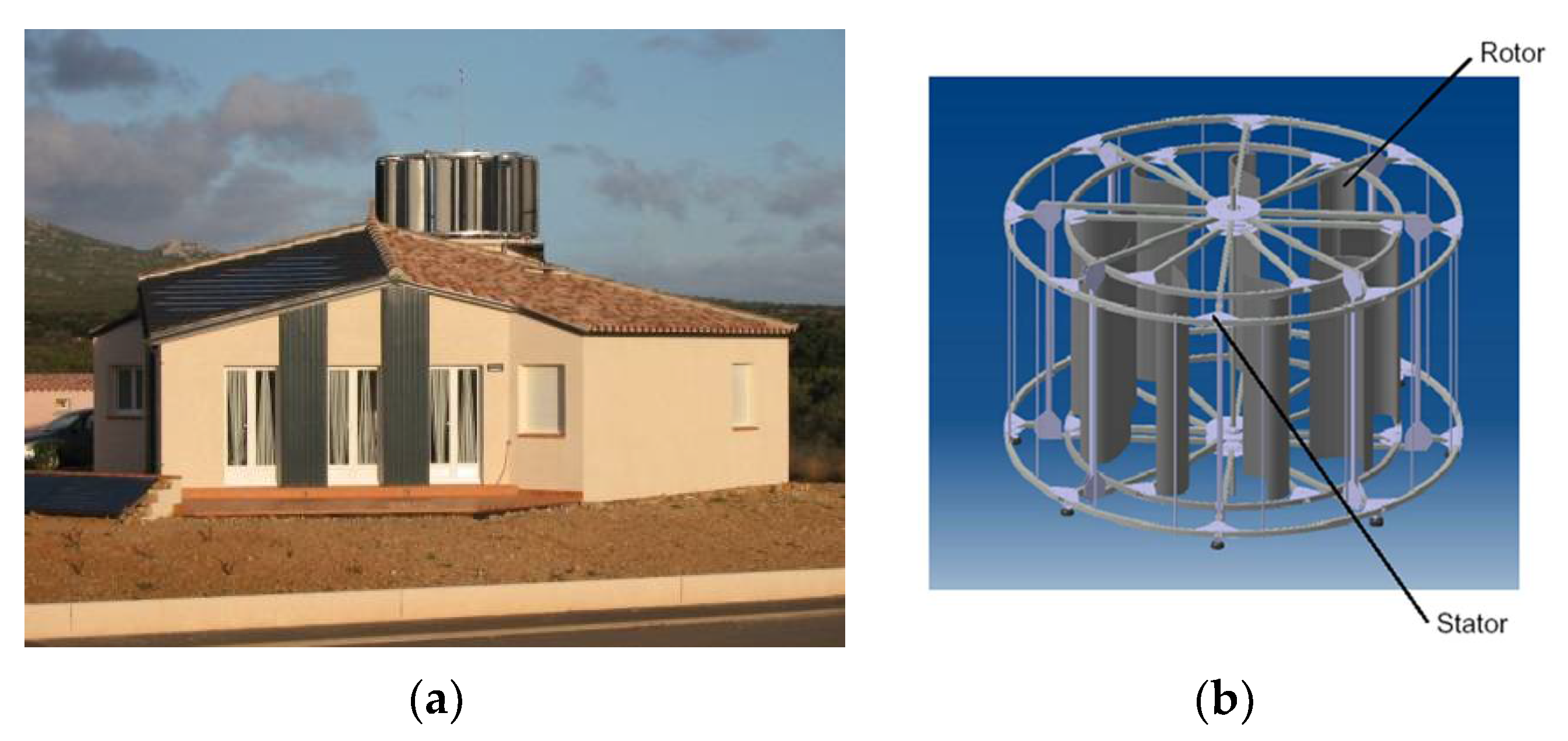
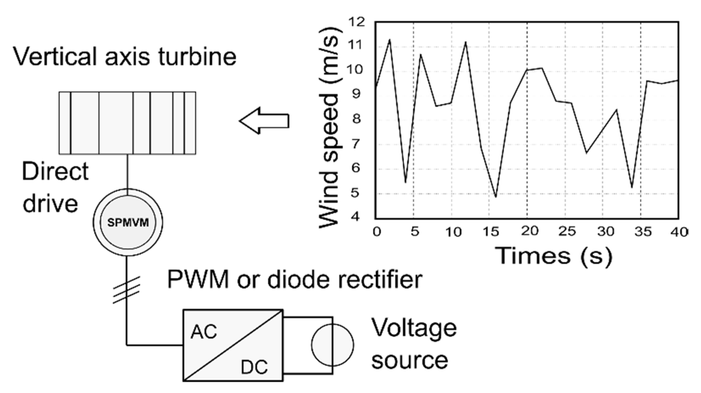
2. The Vertical Axis Wind Turbine

In order to meet market requirements for small wind turbines designed to be used in urban areas, the Gual Industrie Company has developed a vertical axis turbine [5], the StatoEolian, shown in Figure 1. This wind turbine is located in Occitanie region in the south of France. This turbine is comprised of an external stator surrounding a paddle rotor. The stator channels the wind at its optimal force onto the rotor. Performance improvement requires a thorough study of the interactions between the different geometric parameters of the turbine. An important quality of this device is that it even remains operational in severe storms.

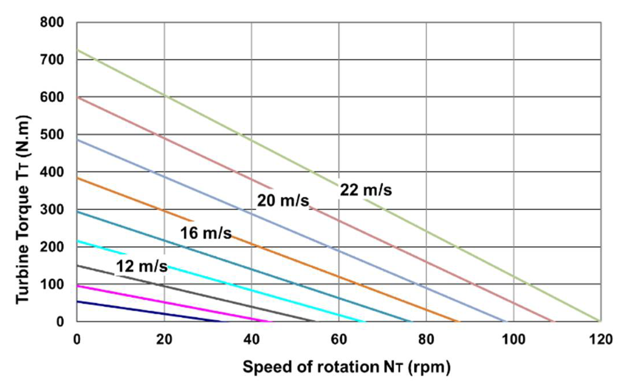
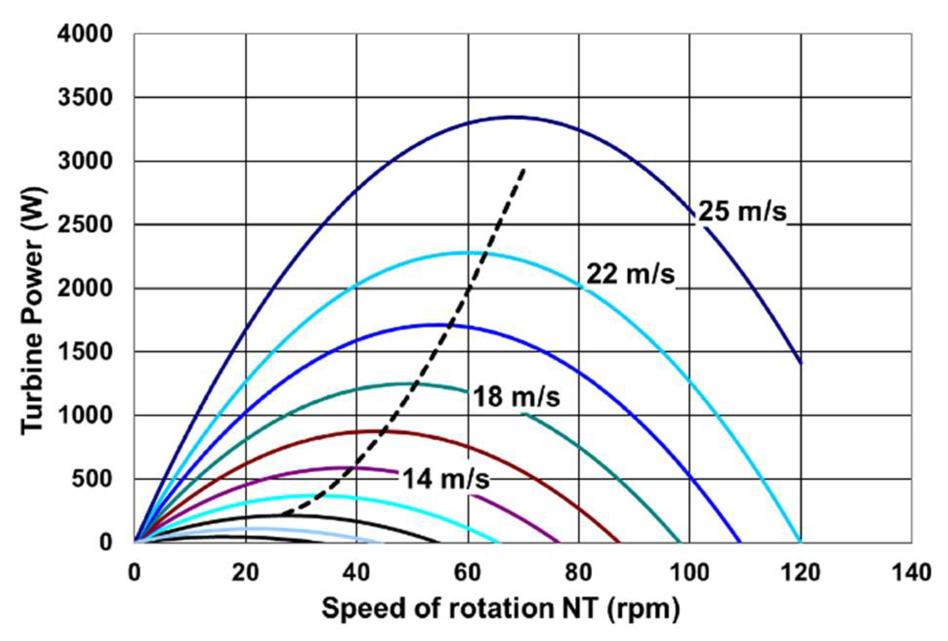
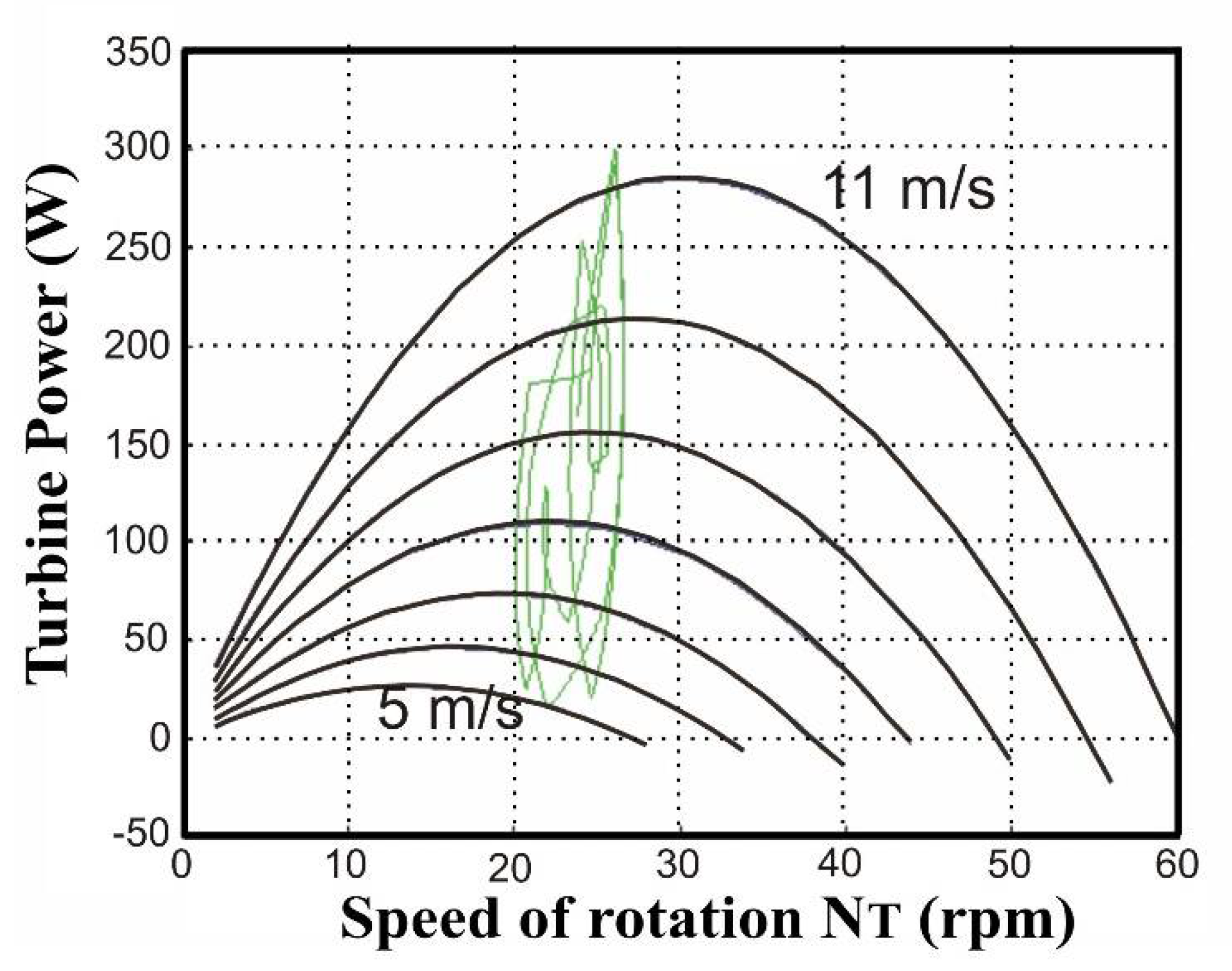
2.1. Characterization of the Turbine

A measurement campaign over several weeks made by the laboratory enabled us to model the aerodynamic torque TT (in Nm) developed by the turbine as a function of wind speed Sw (in m/s), and of rotation speed NT (in rpm):
T T = 1.5 S W 2 0.275 N T S W
This model was used to deduce torque/speed (Figure 2) and power/speed (Figure 3) characteristics for wind speeds ranging from 6 m/s to 22 m/s.
Unlike horizontal axis turbines, the torque value is particularly high when the turbine starts, and it decreases when the rotation speed rises. A more classical bell-shaped curve is observed for power characteristic. One of the main purposes of the energy conversion system, associated with the turbine, will therefore be to keep its working point as close as possible to the maximum power points (dotted curve in Figure 3).

2.2. Generator for the Middle Wind Turbine Characterization of the Turbine

The gearbox is a significant cause of breakdown in a wind turbine, and therefore requires maintenance operations to prevent or correct these failures. This last point is particularly problematic in the case of domestic installations, where users are not likely to possess the skills needed for repairs. The installation could thus be out-of-order for a relatively long time, particularly in a remote area.
The entire energy conversion system must be sturdy. It can face extreme conditions, such as violent winds, possibly without any people being present to perform a safety shut-down. To meet these constraints, and to ensure operation of the turbine without failure for as long as possible, the gearbox is generally oversized in domestic wind turbines. As a result, the gearbox price rises and its integration into the wind energy system becomes more difficult. Another solution is to eliminate the gearbox by using a direct-drive generator.
To make a generator with a high torque-to-weight ratio, essential for implementing a direct-drive, we propose to use a Surface Permanent Magnet Vernier Machine (SPMVM). In this machine, the high torque feature is brought about by the so-called “magnetic gearing effect”: a small movement of the rotor induces a large change in flux, which results in high torque.
By taking into account the high value of mean wind speeds recorded at the turbine installation site, as well as the dimensioning variables of the generator, we calculated its rated values for a wind speed of 19 m/s.
The choice of this wind speed was made based on the wind speed readings at the site where the vertical axis wind turbine is installed. This location is one of the windiest French regions with 300 to 350 days of wind per year. The wind is gusty, with large wind variations and up to maximum wind speeds of 24 m/s. The energetic study allowed the determination of the most interesting peak wind speed for the dimensioning. The choice of this wind speed could have been lower but the aim was also in the case of this turbine to show its ability to operate under high wind speeds. For other sites the choice of this peak speed must be predetermined.
We thus obtained:
  • rated torque TTn = 270 Nm;
  • rated speed NTn = 54 rpm;
  • rated power PTn = 1.5 kW.

3. The Permanent Magnet Vernier Machine

3.1. Principle of Permanent Magnet Vernier Machine

The Permanent Magnet Vernier Machine (PMVM) is an interesting alternative to a conventional Permanent Magnet Synchronous Machine (PMSM). It is less well known despite being the subject of many studies [6,7,8,9,10].
PMVMs allow attainment of high mass torques of interest to obtain direct drive generators suitable for low-speed vertical axis turbines used in proximity to wind turbines. They are also efficient for horizontal axis wind turbines compared to synchronous machines with a large number of poles. The PMVMs have sinusoidal electromotive force (e.m.f.) and the torque ripple is almost zero.
The manufacturing cost and reliability of a PMVM is identical to that of a conventional synchronous machine. The objective of the rest of the article is to show the interest of associating a PMVM with a diode rectifier whose association has been optimized. Thus, the economic cost and reliability of the unit are interesting for an urban or rural environment for small powers.
The Permanent Magnet Vernier Machine we present in this article (PMVM) is an evolution of the Vernier Reluctance Machine (VRM).
The polar coupling in a permanent magnet machine is defined when the fundamental interaction of currents and magnets takes place at the pole pitch level, which is the repeating pattern of the stator winding. The toothed coupling is defined when the fundamental interaction of currents and magnets takes place at the tooth pitch scale, which is the length between two slots. When the winding is distributed, the actuator has two forms of coupling: a toothed type and a polar type. This machine is also called a Vernier effect machine [11].
As shown in Figure 4, the rotor teeth row of the VRM has been replaced by an alternate magnets row to obtain the VRMM.
In a motor, the torque is produced by the interaction of stator and rotor magnetic fields. For its two machines the winding is identical, we have a polyphase winding with pairs of p poles distributed with NS number of slots.
In the PMVM, the tooth pitch is nearly equal to mechanical pitch, defined as the angle covered during an electric period. The number of rotor magnet pairs NR is different from the number of stator teeth NS. The condition to be met is:
| N S N R | = p
Moreover, the electrical frequency f of the PMVM is uniquely linked to the number of pairs of magnets NR, as seen in the following formula:
f = 1 T = N R Ω R 2 π
with ΩR is the rotor speed in rd/s.
The PMVM is a tooth coupling machine. However, the study of this type of machine is identical to that of a conventional synchronous machine. From the Maxwell tensor we can write for the expression of the torque:
T e m = K V R e 2 L 2 π b 1 a n λ 1 d θ
The dimensions Re and L of expression (4) represent the air gap radius and iron length. The coefficient Kv, the speed ratio, is called the Vernier Ratio. This coefficient is difference between the stator field speed and the rotor speed. The stator field speed ΩS is:
Ω S = ω p
The rotor speed ΩR is:
Ω R = ω N R
We obtain:
Ω S Ω R = K V = N R P
We use for our study the linear density of current, λ1, equivalent to stator winding. The periodicity for λ1 is equal to 2π/p, which we express as:
λ 1 = A 1 cos ( p θ )
The amplitude A1 of the linear density depends on the current in the slot, the winding coefficient and the shape of the slot. The stator air gap permeance has equal to 2π/NS.
The air gap magnetomotive force created by the magnet has a periodicity equal to 2π/|NSNR|. The fundamental field component b1an can be expressed as follows:
b 1 a n = k 1 M cos ( ( N S N R ) θ )  
with M as the Remanent flux density of magnet. The coefficient k1, which defines the field amplitude b1an(θ), is deduced using the finite element [10]. Its value, which depends on the ratios of the dimensional proportion parameters, is generally between 0.1 and 0.2.
In the PMVM, the increase in operating frequency allows a gain on the mass–power ratio at very low speed compared to a PMSM.

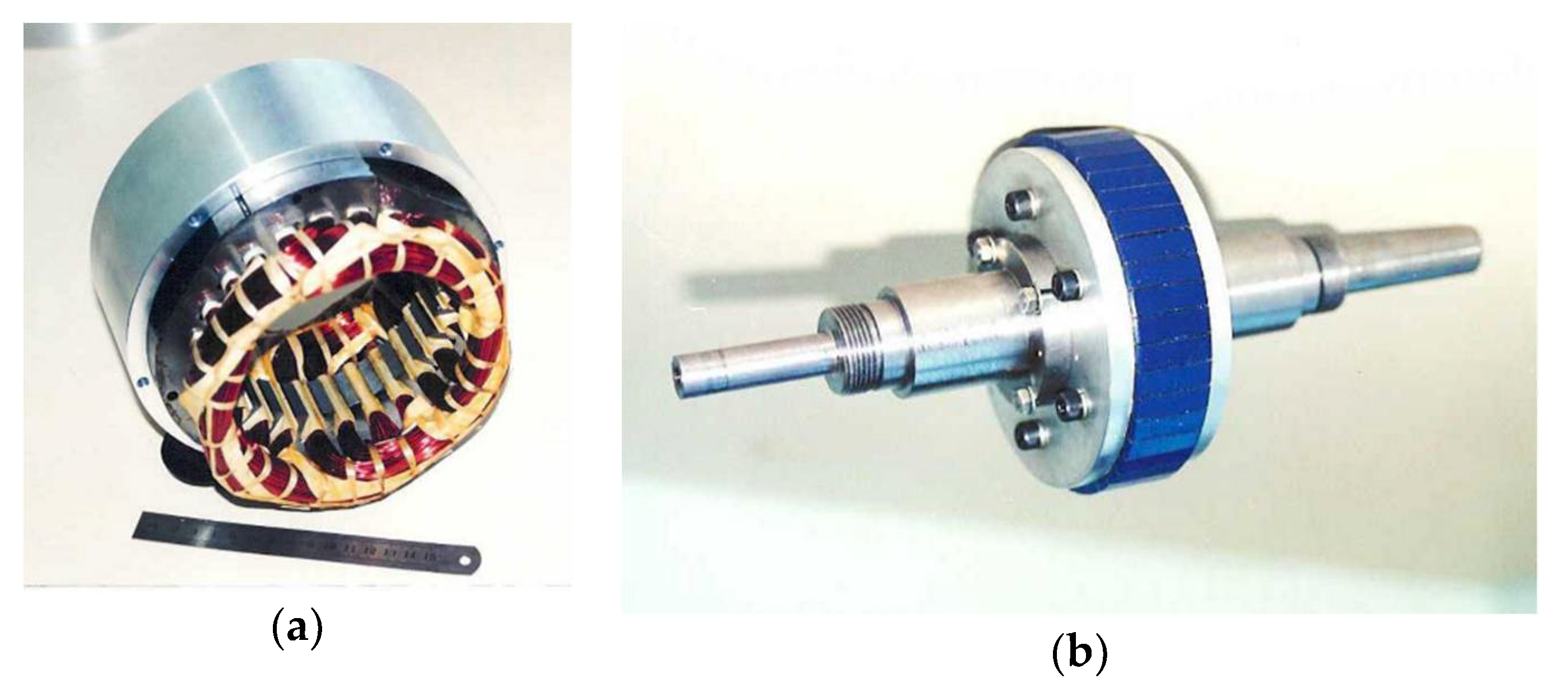
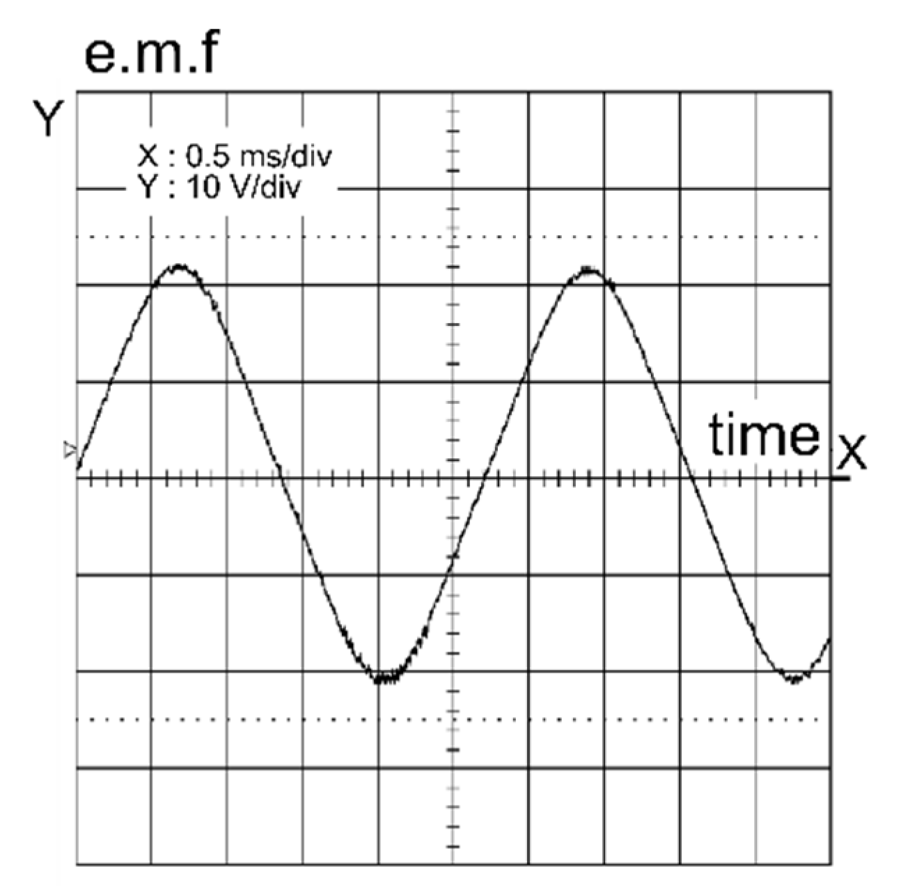
3.2. Example of Permanent Magnet Vernier Machine Prototype

The Figure 5 shows an example of a prototype designed to simulate a Vernier effect generator for an energy conversion system.
This prototype has the following characteristics:
  • p = 2;
  • Ns = 24 stator teeth;
  • Nr = 22 pairs of magnets;
  • Xs synchronous inductance: 61.2 mH;
  • The electromotrice force (e.m.f.) amplitude varies linearly with the rotating speed (emf coefficient: 0.825 V/rad/s).
A particularity of the Vernier machine is that its fem is sinusoidal. There is an e.m.f. of the prototype on Figure 6.

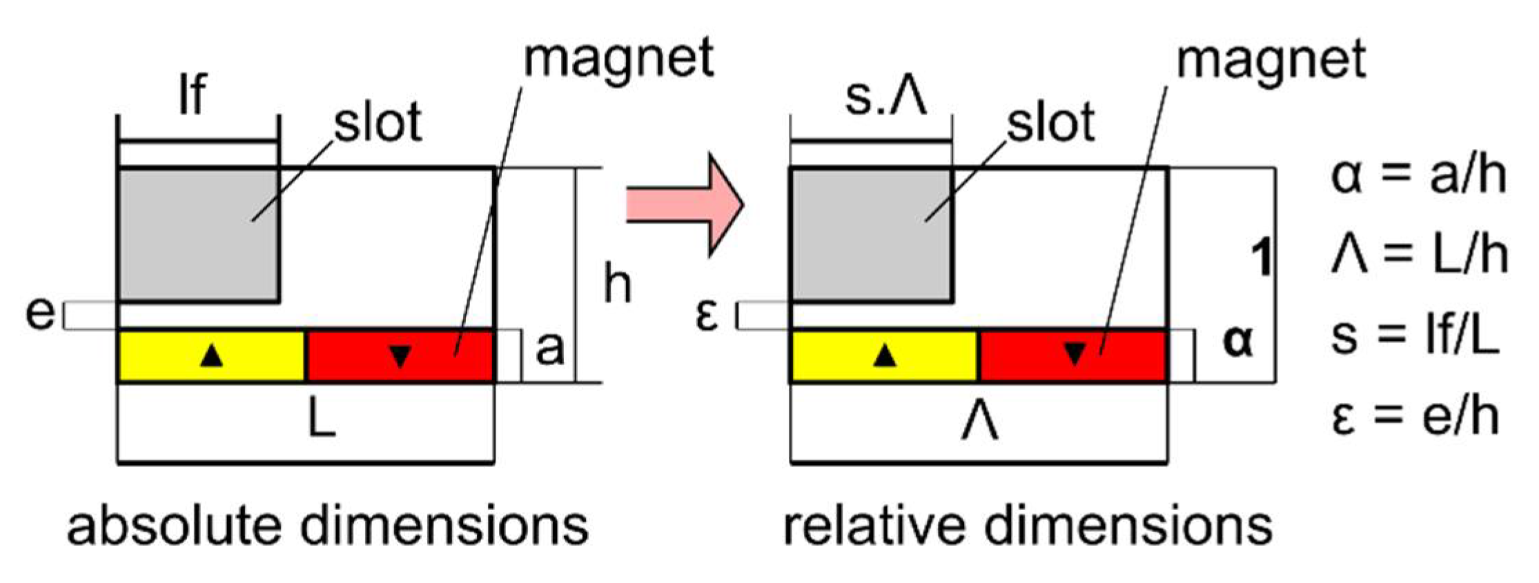
4. Sizing of Generator

4.1. Introduction

Precise calculation of the working of the generator can only be achieved with the finite elements method. However, here we use analytic relations with the aim of making many calculations and making some comparisons between the Vernier structure and synchronous machines with many poles. Most of these analytic relations can be found in [10]. In particular, for the calculation of the torque, we use the relation:
T e m = 4 π R e 3 K f F S
Re: bore radius (m) and Kf, form-factor, defined as the ratio: L/(2Re), L being the laminations’ length.
For the synchronous machine, if the machine is driven so that electromagnetic force FS is in phase with current:
F S = 2 2 M λ 0
M: remanence of rotor magnets (T); λ0: length density of current (A/m), connected to the armature magnetic field.
For the Vernier structure:
F S = M a a + e H K S
a: thickness of magnets (m); e: air gap (m); H: magnetic field density of armature reaction (A/m); KS: coupling coefficient, function of the waveform of feed currents and of the geometric proportions of the machine structure.
We can define an elementary domain, as in Figure 7. This last one is a repetitive cell of the structure. It contains a stator slot and one alternate magnet couple [11].
This elementary domain is defined by five dimensional parameters which have L = domain length (from slot to slot), a = magnet thickness, lf = slot width, e = air gap thickness, and h = domain height. We have the normalized domain with α, ε, ʌ and s. It has been demonstrated that the average tangential force for an elementary domain can be written as:
F S = M α α + ε H K S
We have the characteristics on Figure 8.

4.2. Estimate of Losses and Temperature Rise Product

To design the generator driven by the vertical axis wind turbine, we performed analytical sizing for a rapid overview of the different feasible PMVM with the rated values TTn, NTn and PTn. The calculations are made by taking into account thrusts deduced from geometric, electromagnetic, and thermal constraints.
Copper losses are calculated with the relation (14)
P c o p p e r = ρ m c o p p e r ρ c o p p e r J 2
ρ: copper resistivity (2 × 10⁻⁸ Ω·m); mcopper: copper mass in the machine (kg); ρcopper: copper density (8.9 × 10³ kg/m3); J: surface density of current in stator winding (A/m2).
Core losses are calculated on the basis of data given for laminations designed to work at 400 Hz, by using the relation given in [12], valid with sinusoidal waveforms:
P i r o n = ( 4 k B max 2 f + 2 π 2 α B max 2 f 2 ) m i r o n ρ i r o n
miron: laminations mass; ρiron: alloy density (7.6 × 10³ kg/m3); f: rated frequency (Hz); Bmax: maximum flux density in the laminations (1.5 T).
As the rated frequency is often next to 200 Hz, we will use 0.2 mm thick laminations. With this thickness: α = 6.7 × 10⁻³ and k = 58.

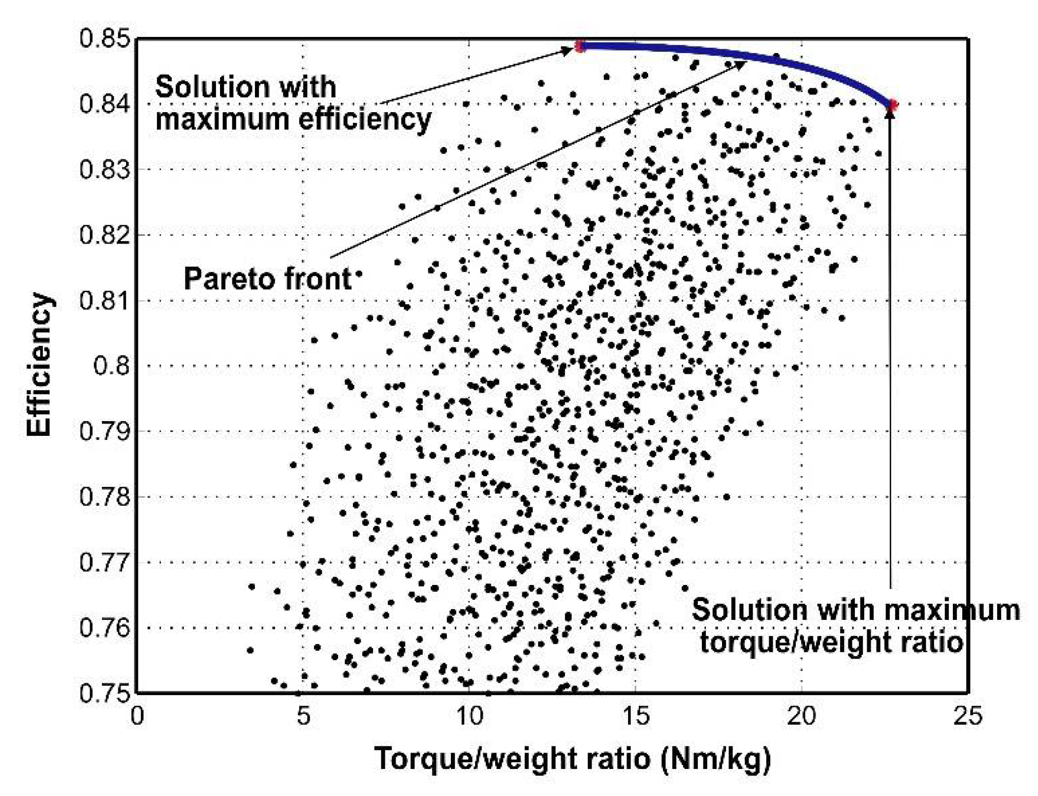
4.3. Results of Analitical Sizing

In terms of the permanent magnet, Neodynium–Iron–Boron Magnets were chosen because of their costs, lower specific weight and a mechanical strength much higher than samarium cobalt.
The PMVM has straight teeth while the PMSM has slot isthmus, so to compare the two machines we estimated the equivalent air gap for a PMSM without slot isthmus at a value of 0.6 mm.
From the rated values of the generator, we calculate the possible solutions, by varying:
  • the form factor Kf;
  • the number of slots per pole and per phase;
  • the number of stator poles;
  • λ0 (for the classical synchronous machine) or H (for the Vernier structure);
  • the thickness of magnets and by taking into account mechanic and electromagnetic limiting factors;
  • demagnetization constraint of magnets;
  • slot pitch > 5 mm;
  • maximum frequency: e.g., 400 Hz;
  • thickness of the yoke;
  • current density in armature winding J < 5 A/mm2.
The evolution of the torque/weight ratio as a function of the rated torque for a rated power of 1.5 kW confirms that the performances of the Vernier machine stands out of those of the synchronous machine all the more because the rated speed of the turbine is low (Figure 9). The same dimensioning can be done for a horizontal axis wind turbine or a different power output.
To analyze the results thus obtained, we plot the efficiency of the feasible solutions as a function of their torque-to-weight ratio (Figure 10) for the PMVM, these two parameters being of prime importance for a direct drive.
With the chosen two objectives, the Pareto front links the solution with the highest efficiency and the solution with the highest torque/weight ratio. As seen in Figure 7, there is a slight difference of efficiency between the solution presenting the highest torque/weight ratio and the solution with the highest efficiency. On the other hand, a small improvement in efficiency leads to a significant decrease in the torque/weight ratio. As a consequence, if the same weighting is given to both objectives, the solution with the highest torque/weight ratio is the more interesting one to implement in our wind energy system. The main characteristics of the resulting machine are listed in Table 1.
For comparison, we performed sizing on a conventional synchronous machine with the same rated values, also maximizing the torque/weight ratio. The torque/weight ratio is twice as high with the SPMVM. However, we can note the low power factor of the Vernier machine, when it is close to one for the conventional machine.
As a reminder, the calculations are made for a torque TTN = 270 N.m and a rotation speed NTN = 5 rpm.
A characteristic of Vernier machines is that they have a lower power factor than conventional synchronous machines. During motor operation it allows us to dimension the power system. The over-sizing of the power system is largely compensated by the high torque of the actuator.
With the SPMVM behaving externally like a synchronous machine without saliency. The electrical model for this machine is the same as that of a classical synchronous magnet machine. We have E electromotive force (e.m.f.), Rs stator resistance, Xs synchronous reactance and V single voltage at the stator terminals.
The Fresnel diagrams obtained with a diode rectifier and with a Power Wave Modulation (PWM) rectifier are presented in Figure 11. The phasors shown in the diagrams are fundamental quantities.
These diagrams show that a low power factor will require oversizing of the PWM rectifier to achieve the same transmitted power. Concerning the diode rectifier, the torque/weight ratios presented above were obtained by assuming that the e.m.f. was in phase with the stator current, so the expected performance will not be reached at the rated current.
As the low power factor of the generator is a drawback with the two usual types of rectifiers, we want to increase its value. With the efficiency and torque/weight ratio, we then have three optimization objectives. To potentially identify others, we will now consider the energy conversion system as a whole.

5. Study of the Vernier Generator and Rectifier Association

5.1. Introduction

To investigate the association of the Vernier machine with the two types of rectifiers, we model the complete energy conversion system with Simulink. The turbine is simulated with (1). The PMVM is modeled using the classical relations of the synchronous machine, with some adaptations to take its particularities into account. The converters are represented by average models. With experiments on a test bed [13], we have shown that the overall model offers a good estimate of the energy produced by the turbine, but that it is less precise for converter and machine losses.
As a model of wind, we used a profile with a mean speed of 8 m/s and including sharp variations, so as to study the dynamic behavior of the conversion system when submitted to uneven wind gusts that commonly arise in urban areas (Figure 12).
We used the parameters given in Table 1 for the SPMVM. With an additional condition imposing a 120-V phase voltage under rated speed, we calculated the parameters of the machine’s electrical model:
  • Back-emf coefficient: Ke = 11.3 V/rad/s
  • Stator inductance: Ls = 10.4 mH
  • Stator resistance: Rs = 1.12 Ω.
The rectifier associated with the generator can feed a DC link with a fixed or variable voltage (see Figure 12). The load can be an accumulator, possibly fed by a chopper, or an inverter connected to a local grid [14,15,16,17].
Considering the high synchronous reactance of the PMVM, it is better to use a voltage source at the output of the diode bridge rectifier. We thus obtain phase currents that are naturally sinusoidal in the machine and the total harmonic distortion of the stator voltage is lower than with a smoothing inductor.

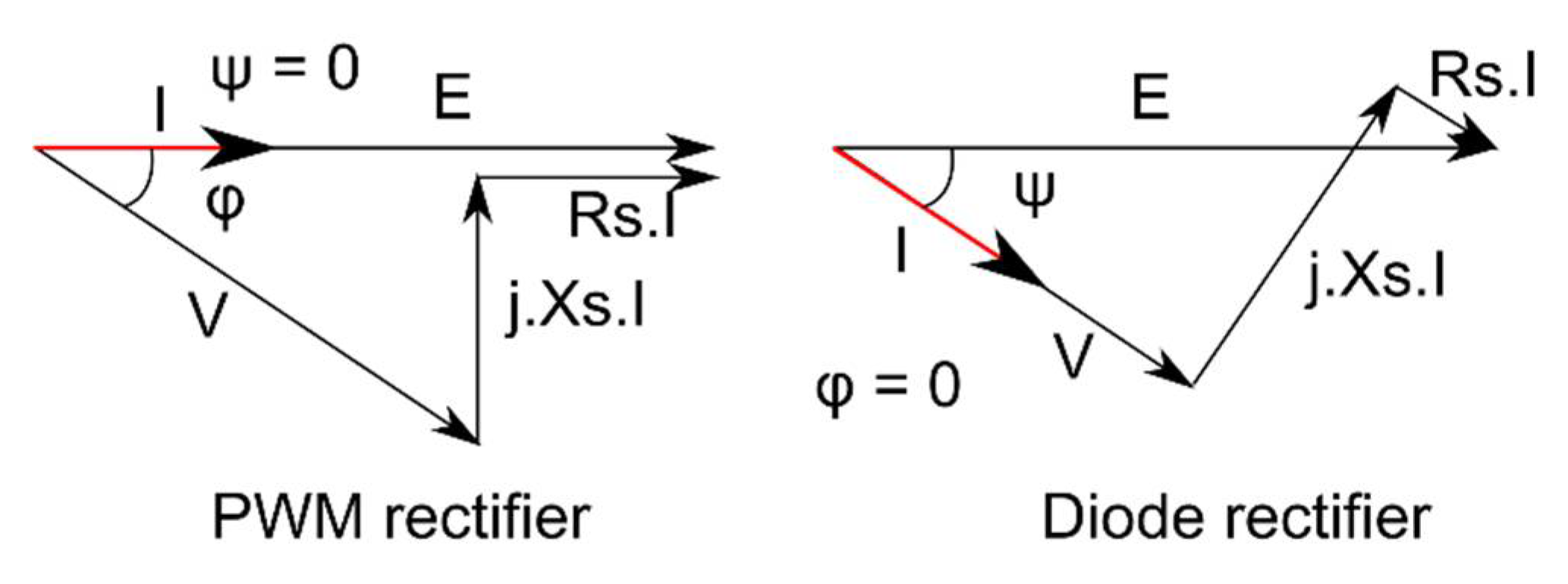
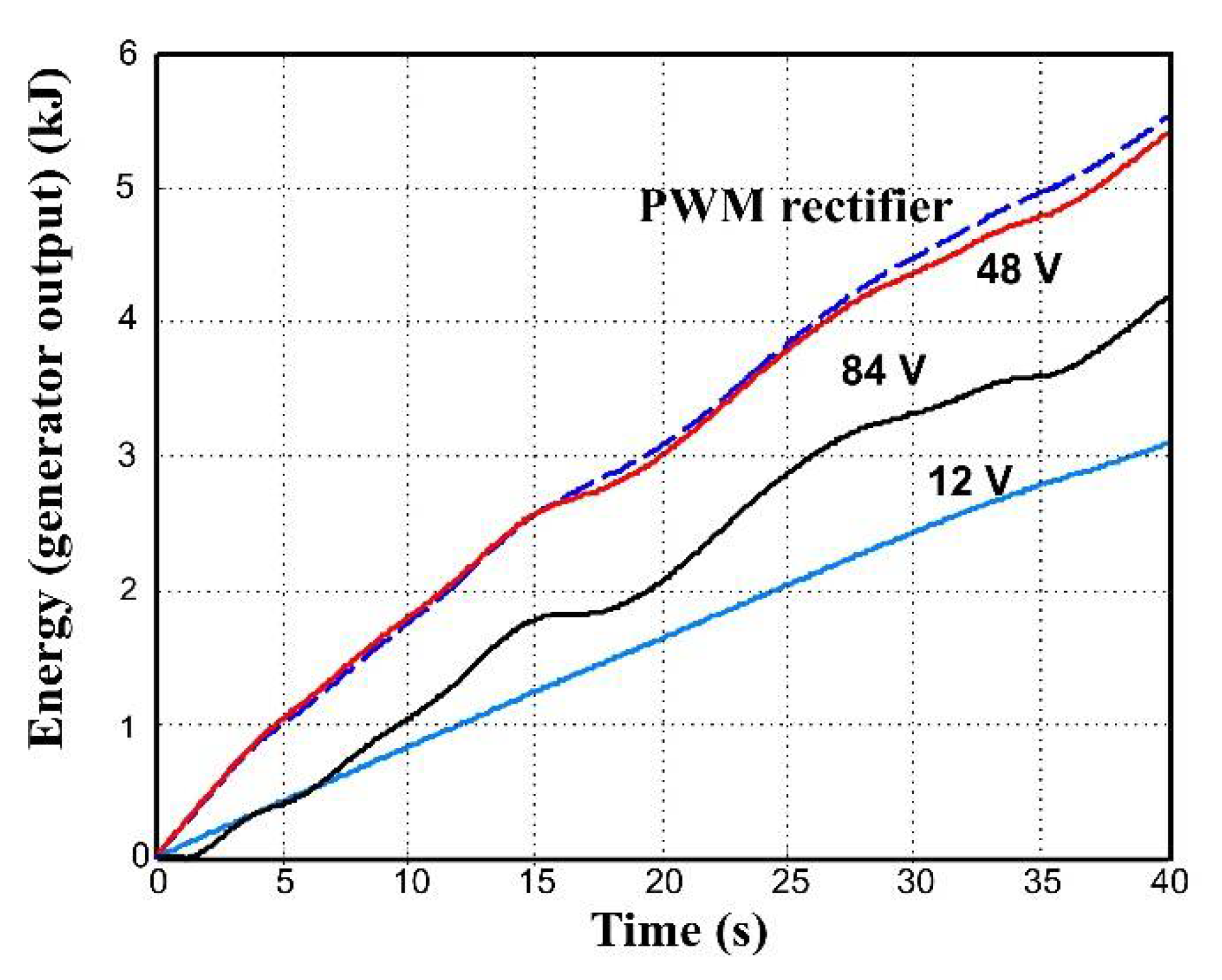
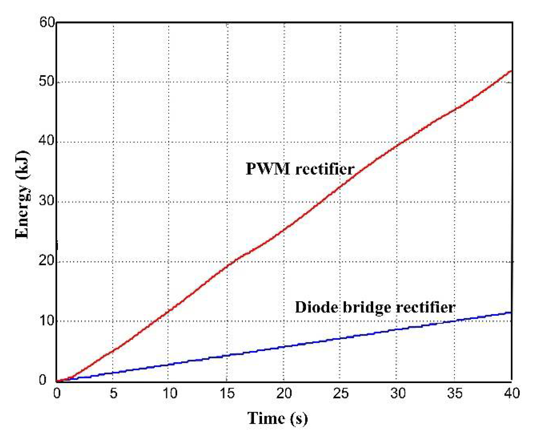
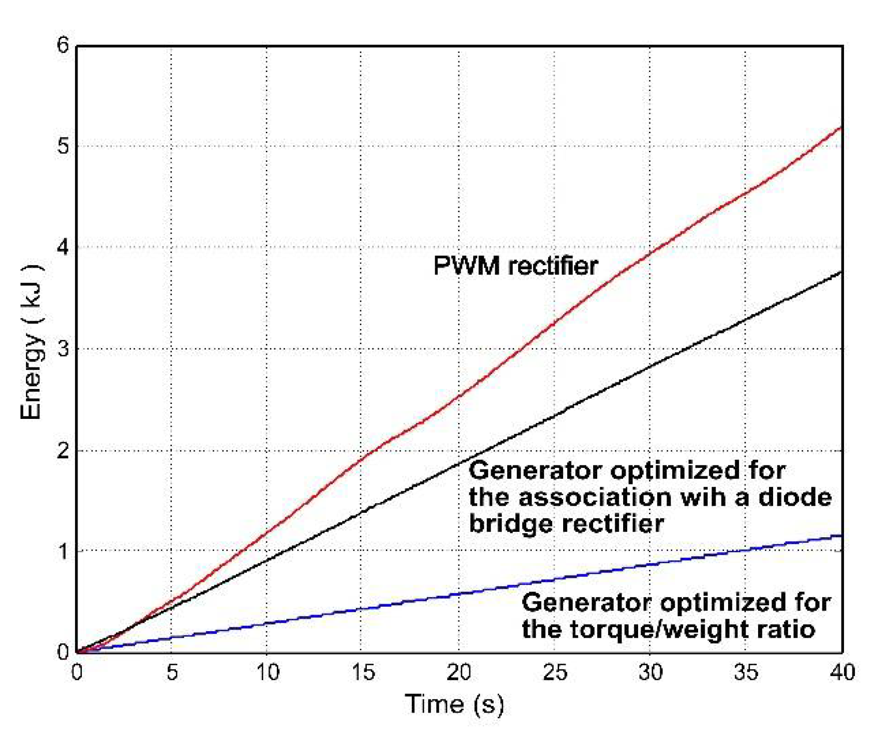
5.2. Vernier Machine PWM Rectifier Association

With a PWM rectifier, we can drive the generator to maintain the operating point of the turbine close to the maximum power point locus (Figure 3) [18,19,20,21,22]. The torque vs. speed characteristic of the turbine being known, we can use the driving method shown in Figure 13.
From a speed measurement, the torque set point necessary to keep the working point of the turbine on the maximum power point locus is deduced. This value is used to calculate the stator current set point in a rotating frame, and the resulting control action is transformed back to the stationary frame for execution. The working point trajectory of the turbine resulting from this control method is shown in Figure 14.

5.3. Vernier Machine Diode Rectifier Association

The diode bridge rectifier is an easy-to-use, low-cost, and sturdy converter, which is what makes it a very interesting choice for a domestic installation. On the other hand, as it is not a driven converter, it obviously does not make it possible to impose a working point on the turbine. Consequently, the energy conversion system must be designed as a whole to obtain a working point trajectory naturally, which will come close to the one shown in Figure 14.

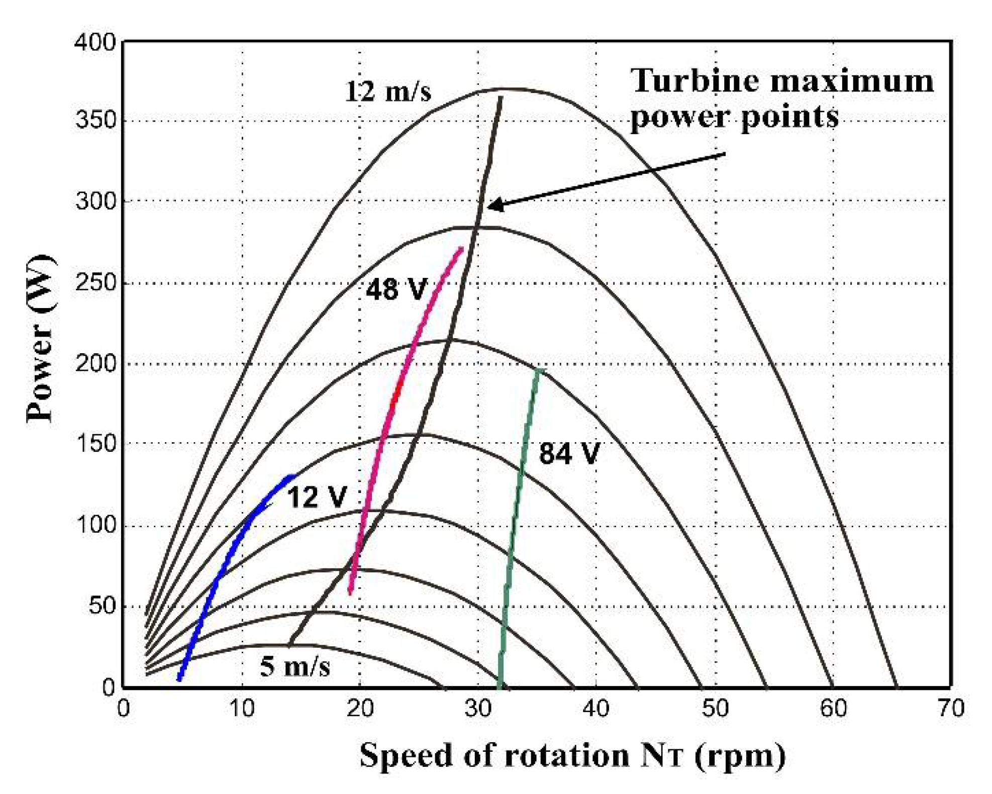
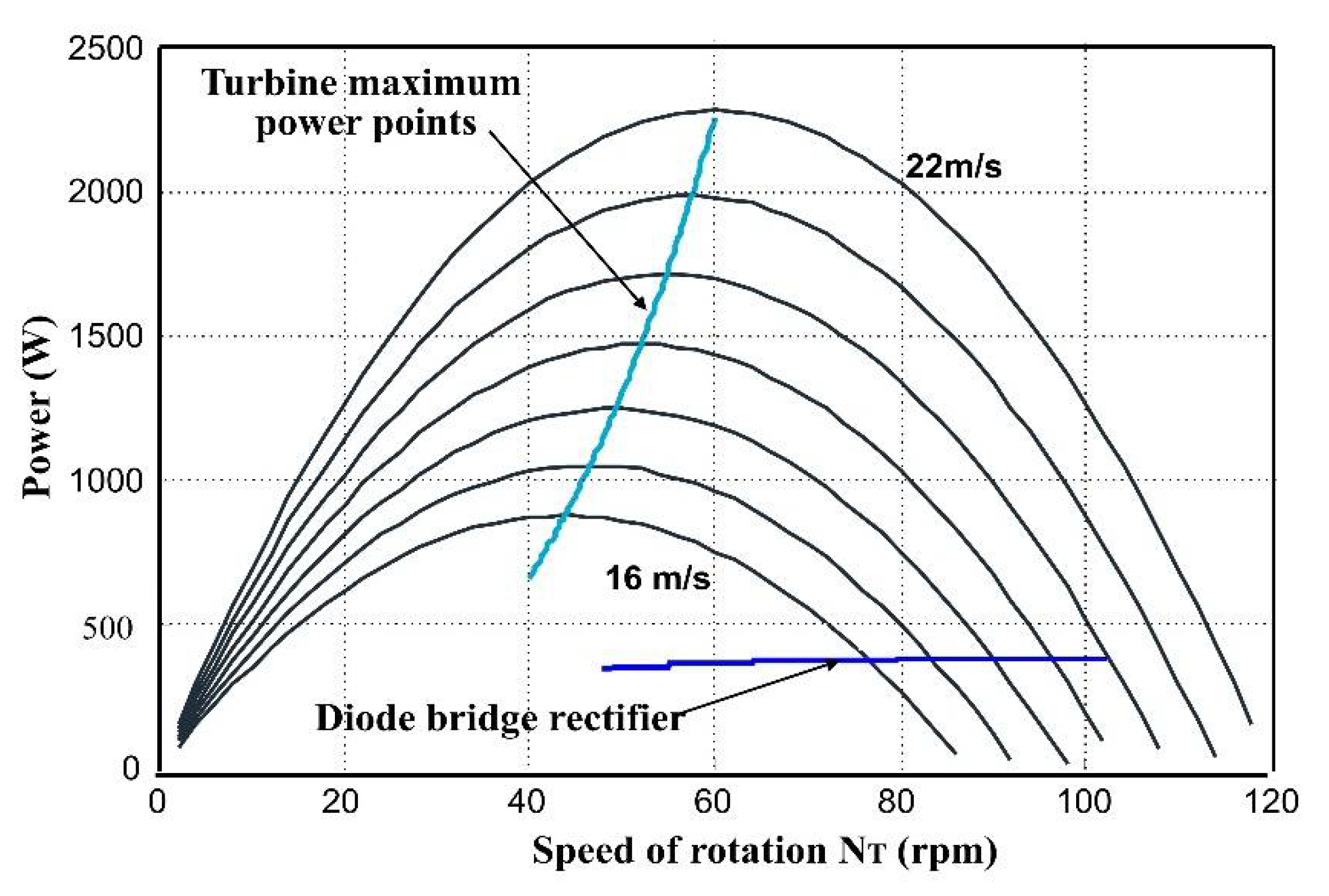
5.3.1. Constant DC-Link Voltage

In the case of constant DC-link voltage, the voltage value must be chosen to reach a compromise. For a high voltage value, the diode bridge will conduct only for high-speed, low-power working points of the turbine. With a low voltage value, the working point of the turbine will settle at low speeds, which also correspond to low power.
Therefore, there is an optimal voltage value with which the working point will settle close to the maximum power point locus (Figure 15), thus leading to maximum energy recuperation (Figure 16).
If we pay attention to the energy produced by this conversion system, depending on whether a diode bridge or a PWM rectifier is used, the difference is much more distinct for high wind speeds: with the diode rectifier, when the wind speed rises, the derivative of the generator torque with respect to the speed of rotation δTg/δΩ tends towards negative values. In that case, the working point becomes unstable and the turbine speed increases rapidly. The working point moves away from maximum power points and, if we refer to what is produced with a PWM rectifier, the turbine is clearly under-exploited. As a consequence, we cannot take advantage of the turbine’s ability to work with strong winds.
To illustrate what happens under high wind speed conditions, we use a wind profile with the same shape as that in Figure 8, but with a mean value of 19 m/s, that is, the wind speed with which we determined the rated values. With a DC-link voltage of 48 V, which is the optimal value for an average wind speed of 8 m/s, the working point trajectory of the resulting turbine is shown in Figure 17, and the energy collected on the DC-link is divided by more than four compared to the energy produced with a PWM rectifier (Figure 18).

5.3.2. Variable DC-Link Voltage

As a starting point, we use the power expression on the generator output. From there, we can obtain the expression of the DC bus voltage uDCM for which the generator associated with a diode bridge supplies maximum power to the DC bus. Using the notation from Figure 11 and with a unit power factor, we obtain:
P = 3 V I = 3 ( 2 π U D C ) I
In addition, from Figure 8, diode rectifier, we can deduce the stator current (I):
I = V R S R S 2 + X S 2 + ( K e ω N R ) 2 ( R S 2 + X S 2 ) ( X S V ) 2 R S 2 + X S 2
Ke being the e.m.f. coefficient of the PMVM.
Expression (16) thus becomes:
P = 3 V R S 2 + X S 2 ( V R S + ( K e ω N R ) 2 ( R S 2 + X S 2 ) ( X S V ) 2 )
Differentiating this expression with respect to the DC bus voltage UDC, we deduce that power P is maximum for UDCM:
U D C M 2 = ( K e ω N R ) 2 R S 2 + X S 2 ( R S 2 + X S 2 R S ) ( 2 π ) 2 X S 2
If we note stator angular frequency ω, as XS2 = (LS · ω)2 >> RS2, this expression becomes:
U D C M 2 = ( K e ω N R ) 2 ( L S ω R S ) ( 2 π ) 2 L S ω = ( K e ω π 2 N R ) 2 ( 1 R S L S ω )
If the wind speed is 8 m/s, maximum turbine power is reached when N = 20 rpm. At this operating point, the stator frequency is 68 Hz and it can be found with (20) that the optimal DC bus voltage is about 48 V. If the wind speed reaches 19 m/s, the turbine’s maximum power is obtained at nominal rotating speed, giving a stator frequency of 199 Hz. An amount of 48 V as the DC bus value is no longer optimal: the new optimal voltage UDCM is obtained from (20) and is about 96 V.
If we may vary the DC bus voltage, we can improve the operation of the energy conversion system with a diode bridge, by adapting this voltage to the rotating speed. However, this solution reduces simplicity, sturdiness, and does not bring significant improvement in power production. If we apply (18) with a voltage UDC = 96 V, the power is about 470 W, which is much lower than the 1470 W that the turbine can potentially produce when the wind reaches 19 m/s.

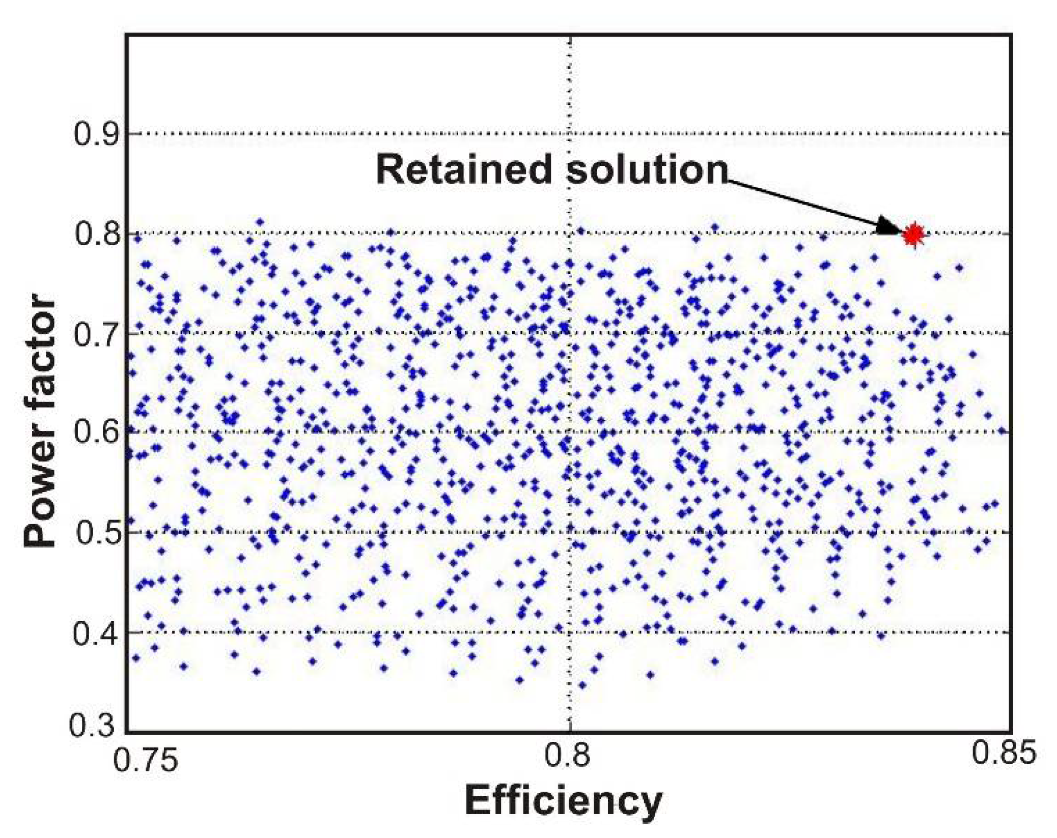
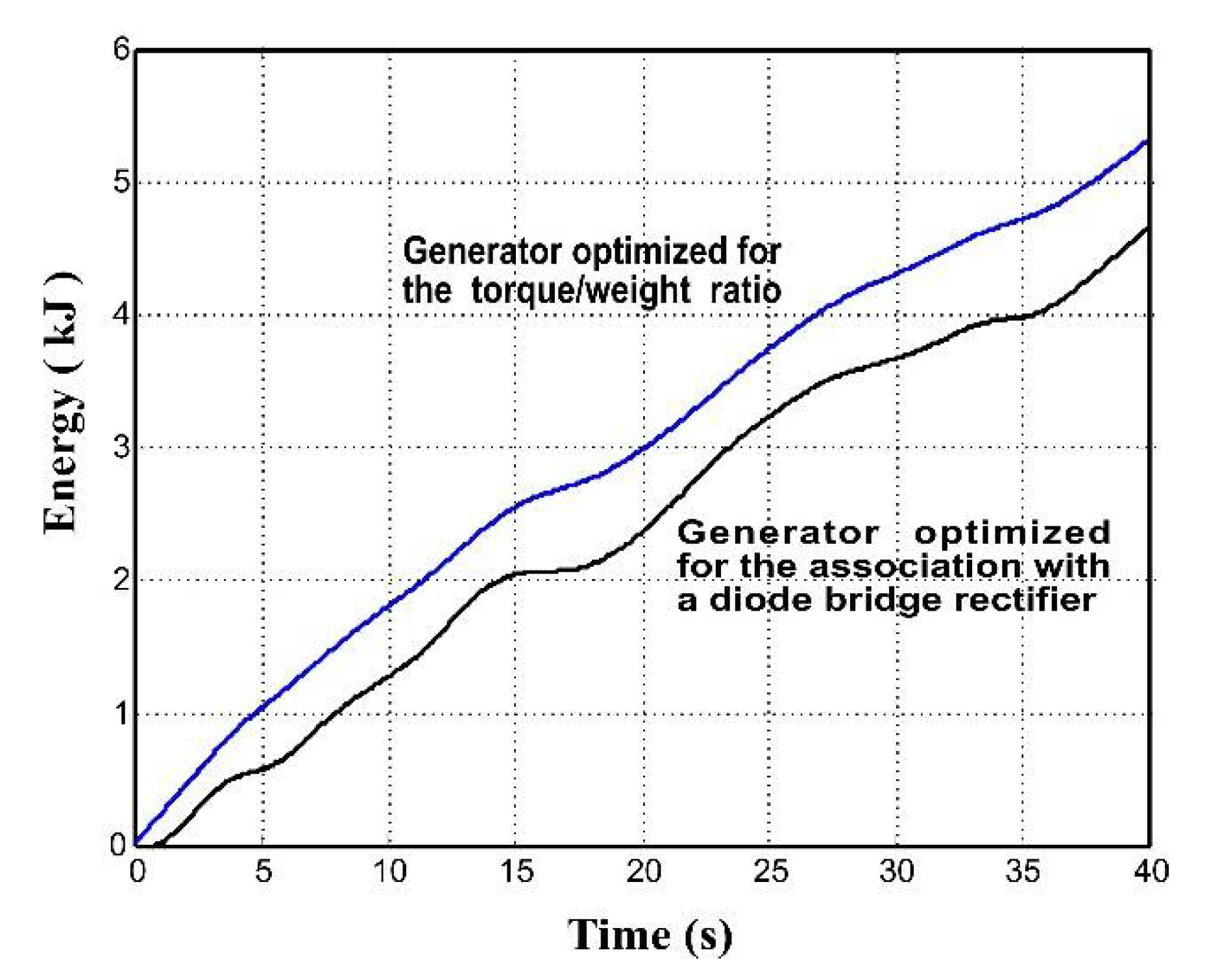
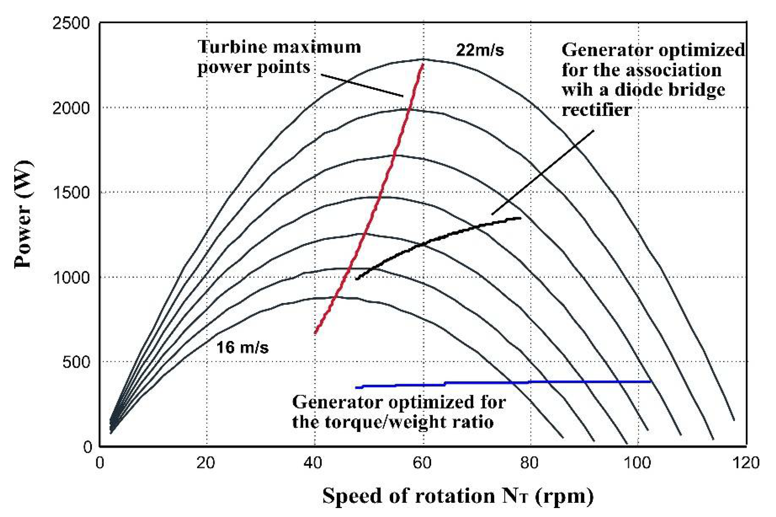
5.3.3. Machine Optimization for a Diode Bridge Rectifier

Using (18) and (20), we can plot the evolution of the maximum power versus speed produced by the association of the generator and the diode bridge rectifier. Figure 19 is obtained by using this plot and the characteristic giving the maximum power produced by the turbine versus speed.
There is a speed limit Nlim, beyond which the generator cannot transmit all the power produced by the turbine to the DC bus.
The generator’s rated values are specified for a wind speed of 19 m/s. Thus, among the solutions plotted in Figure 10, we look for a generator giving a speed Nlim as near as possible to 54 rpm (speed of the turbine maximum power point for this wind speed in Figure 3).
We can deduce Nlim or here Ωlim expression from the relation giving the maximum power of the turbine as a function of the rotating speed:
P M = K T × Ω 3 = ( 1 2 C p o p t S T ρ R 3 λ o p t 3 ) × Ω 3 = 9.4 × Ω 3
CPopt: maximum power coefficient of the turbine: CPopt = 7.62/100; ST: turbine area “seen” by the wind: ST = 4.5 m2; ρ: air density: ρ = 1.25 kg/m3; R: turbine rotor radius: R = 0.9 m; λ represents the ratio: (R · Ω/Sw), Sw being the wind speed; λopt is the value of λ for which Cp = CPopt either λopt = 0.26.
From (18) and (20), we can then deduce the expression of the maximum power at the generator output as a function of speed, and equate it to (22). The only coherent solution is:
Ω lim ( r d . s 1 ) = K e 3 2 K T L S N R R S 2 L S N R = Ω 1 ( 1 ) Ω 1 ( 2 )
From this expression, we can make the following remarks:
  • The second term of (22) is smaller than the first: using the simulation parameters listed in introduction of Section 5, we find that the second term of the expression Ω1 (2) represents about 8% of the first one.
  • Ke is proportional to the number of winding turns, and LS are proportional to the number of turns squared. Thus, Ωlim is independent of this number of turns: changing the winding cannot improve system operation. Thus, if we want to modify Ωlim, we are interested at first by the first term Ω1 (1) of (22).
To obtain an expression of Ke and LS, we use the following relations:
K e = U r P F Ω r
with Ur: stator voltage at rated speed (Ur = 120 V), PF: power factor, Ωr: rated speed (rad·s−1).
L S = sin ( cos 1 ( P F ) ) U r 2 π I r f r
fr rated frequency:
f r = N R . Ω r 2 π
Ir rated stator current:
I r = P r 3 U P F
Pr: rated power.
Using relations (23) to (26), we find that the first term in (22) can be written:
Ω 1 ( 1 ) = P r P F 2 K T Ω r sin ( cos 1 ( P F ) )
The application sets the rated values for power and rotating speed. Thus only the power factor remains as a variable.
The second part of Equation (22) can be written as:
Ω 1 ( 2 ) = P r R S Ω r 6 U r 2 P F Ω r sin ( cos 1 ( P F ) )
Ω1(2) being small in comparison with Ω1(1), we can approximate that stator resistance does not change from one machine to another. The stator voltage at rated speed Ur will remain unchanged too. We can then plot Ωlim as a function of the power factor (Figure 19).
Ωlim increases far more quickly when the power factor is greater than 0.9. If we want to obtain Ωlim = 54 rpm, we need a power factor equal to 0.928. However, the curve on Figure 20 is plotted without imposing any limit on the machine stator current.
Using (18), we calculate that a machine with a power factor of 0.928, a rated power of 1.5 kW, and a rated voltage of 120 V, would have a rated current of 4.5 A, but its stator current would reach 7.5 A at the working point. So as to not oversize the machine, among the solutions calculated in Table 1, we seek the solution that represents the best compromise between efficiency and power factor while maintaining a high torque to weight ratio (Figure 21).
In Table 2, the chosen solution is compared to the PMVM presented in Table 1.

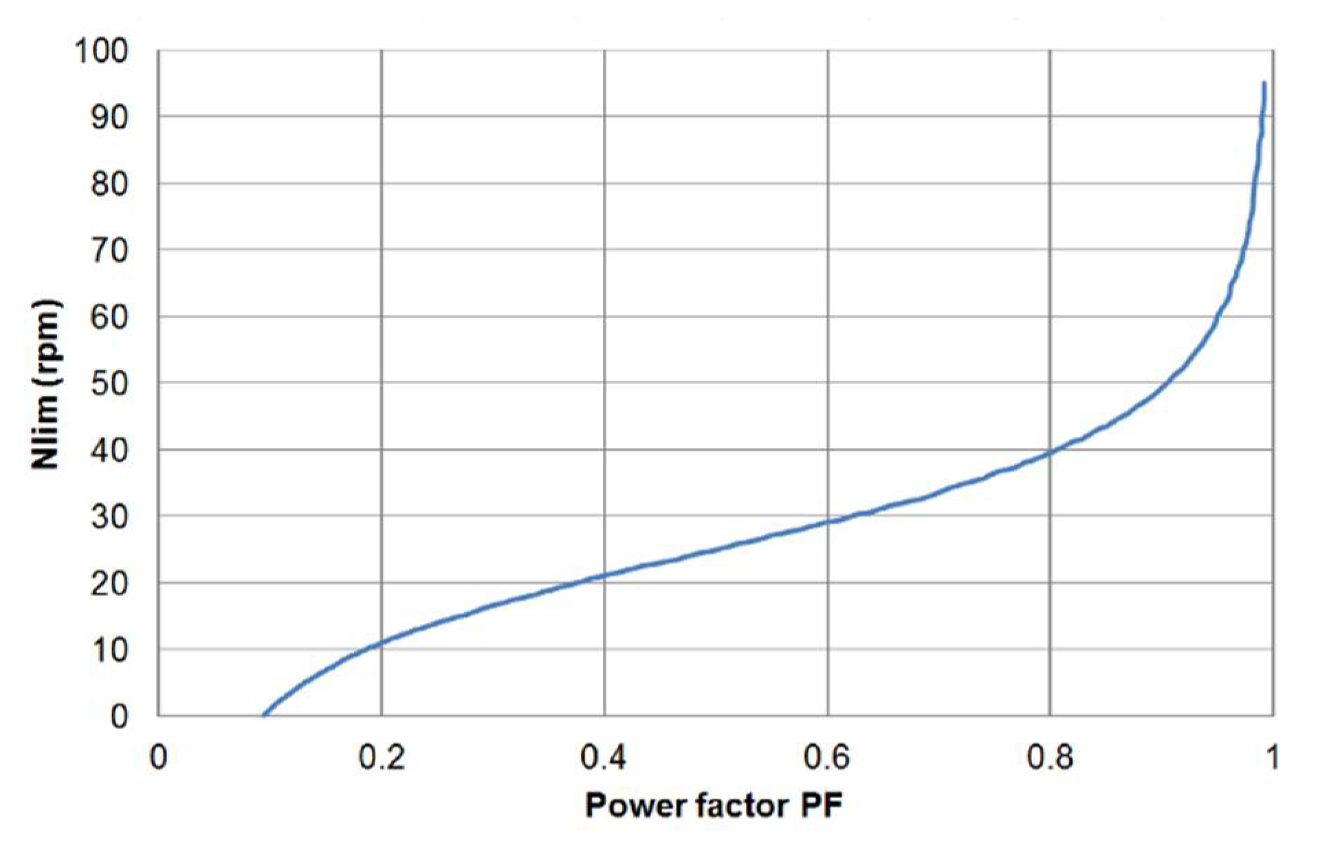
5.3.4. Improvement Brought by the Generator with a High Power Factor

To simplify the energy conversion system, we work with a constant DC voltage at the rectifier output and, by using simulations, we try to evaluate the improvements that can be expected in energy production with a machine optimized for association with a diode bridge rectifier. In these simulations, we use, for every generator, the DC voltage calculated using (20) for speed Ωlim: this voltage seems to be the most appropriate for maximum energy production over the entire wind speed variation range. For the generator optimized for the torque-to-weight ratio: UDC = 48 V, for the generator optimized for association with the diode rectifier: UDC = 96 V.
With an average wind of 8 m/s, Figure 16 shows that the generator optimized by considering the torque/weight ratio can produce the power with a PWM rectifier. In comparison with this generator, we obtain 12% less power with the generator optimized for association with the diode bridge (Figure 22).
With a wind profile centered on 19 m/s, the generator optimized for the diode bridge makes it possible to obtain working points nearer the maximal power points than with the machine with a high torque-to-weight ratio (Figure 23).
The energy at the generator output, despite being 30% lower than with a PWM rectifier, represents three times the energy we can obtain with a high torque/weight generator associated with a diode bridge (Figure 24).
With a high power factor generator, we can then maintain high-performance over a wide wind speed range.

6. Conclusions

By using simulations, we showed that the association of a PMVM with a diode rectifier in a wind energy conversion system can result in good performance, requiring a specific design of the generator for the association.
In the application studied in this article, the system prioritizing generator weight and compactness seems to offer high performance for low wind speeds, but is far less efficient in case of strong winds. Therefore, to best exploit the wind turbine without oversizing the generator, a concession must be made on the torque-to-weight ratio in favor of the power factor. This concession, however, is justified by the simplicity and the sturdiness of the energy conversion system thereby obtained.
We are also studying other converter architectures associated with the Vernier generator effect, its converters already being studied for wind energy conversion.
The combination of an optimized Vernier generator with a diode rectifier can be an economical solution for small vertical or horizontal axis wind turbines. For this machine there are no mechanical feasibility constraints even for small yoke, tooth or magnet dimensions.

Author Contributions

Conceptualization, designed, analysis, writing—original draft preparation, P.E. and I.M.; supervision this project, P.E. and D.M.; writing—review and editing, P.E. All authors have read and agreed to the published version of the manuscript.

Funding

This research received no external funding.

Institutional Review Board Statement

Not applicable.

Informed Consent Statement

Not applicable.

Data Availability Statement

The study did not report any data.

Conflicts of Interest

The authors declare no conflict of interest.

References

  1. Chen, Z.; Guerrero, J.M.; Blaabjerg, F. A review of the state of the art of power electronics for wind turbines. IEEE Trans. Power Electron. 2009, 24, 1859–1875. [Google Scholar] [CrossRef]
  2. Milivojevic, N.; Stamenkovic, I.; Schofield, N. Power and Energy Analysis of Commercial Small Wind Turbine Systems. In Proceedings of the IEEE International Conference Industrial Technology (ICIT), Vina del Mar, Chile, 14–17 March 2010; pp. 1739–1744. [Google Scholar] [CrossRef]
  3. Corbus, D.; Baring-Gould, I.; Drouilhet, S.; Jimenez, T.; Newcomb, C.; Flowers, L. Small wind turbine testing and develop-ment applications. In Proceedings of the WindPower’99, Burlington, VT, USA, 20–23 June 1999. AC36-99GO10337. [Google Scholar]
  4. Ani, S.O.; Polinder, H.; Ferreira, J.A. Comparison of Energy Yield of Small Wind Turbines in Low Wind Speed Areas. IEEE Trans. Sustain. Energy 2012, 4, 42–49. [Google Scholar] [CrossRef]
  5. Modi, V.J.; Fernando, U.K. On the performance of the Savonius wind turbine. J. Sol. Energy Eng. 1998, 111, 71–81. [Google Scholar] [CrossRef]
  6. Llibre, J.F.; Matt, D. A Cylindrical Vernier Reluctance Permanent-Magnet Machine. Electromotion J. 1998, 5, 35–39. [Google Scholar]
  7. Lipo, T.; Toba, A. Generic torque-maximizing design methodology of surface permanent-magnet vernier machine. IEEE Trans. Ind. Appl. 2000, 36, 1539–1546. [Google Scholar] [CrossRef]
  8. Mény, I.; Enrici, P.; Huselstein, J.J.; Matt, D. Direct driven synchronous generator for wind turbines (Vernier reluctance magnet machine). In Proceedings of the ICEM’2004, Cracovie, Pologne, 5–8 September 2004. [Google Scholar]
  9. Mény, I.; Enrici, P.; Didat, J.R.; Matt, D. Analytical dimensioning of a direct-driven wind generator. Use of a variable reluc-tance magnet machine with Vernier effect. In Proceedings of the Electromotion 05, Lausanne, Switzerland, 27–29 July 2005. [Google Scholar]
  10. Llibre, J.F.; Matt, D. Performances comparées des machines à aimants et à réluctance variable. Maximisation du couple massique ou volumique. J. Phys. III 1995, 5, 1621–1641. [Google Scholar]
  11. Enrici, P.; Dumas, F.; Ziegler, N.; Matt, D. Design of a High-Performance Multi-Air Gap Linear Actuator for Aeronautical Applications. IEEE Trans. Energy Convers. 2016, 31, 896–905. [Google Scholar] [CrossRef]
  12. Hoang, E. Etude, modélisation et mesure des pertes magnétiques dans les moteurs à réluctance variable à double saillance. Ph.D. Thesis, Laboratoire d’Electricité, Signaux et Robotique (LESiR), Ecole normale Supérieure de Cachan, Cachan, France, 19 December 1995. [Google Scholar]
  13. Meny, I. Chaîne de Conversion Éolienne de Petite Puissance: Optimisation D’une Génératrice Spécifique à Entraînement Di-rect, Développement de la Chaîne de Conversion. Ph.D. Thesis, Department of Electrical Engineering, Université Montpellier, Montpellier, France, 6 July 2005. [Google Scholar]
  14. Matt, D.; Martirè, T.; Enrici, P.; Jac, J.; Ziegler, N. Passive Wind Energy Conversion System Association of a direct-driven synchronous motor with Vernier effect and a diode rectifier. In Proceedings of the Electrotechnical conference MELECON 2008, Ajaccio, France, 5–7 May 2008. [Google Scholar] [CrossRef]
  15. Wang, J.; Xu, D.; Wu, B.; Luo, Z. A Low-Cost Rectifier Topology for Variable-Speed High-Power PMSG Wind Turbines. IEEE Trans. Power Electron. 2011, 26, 2192–2200. [Google Scholar] [CrossRef]
  16. Kana, C.; Thamodharan, M.; Wolf, A. System management of a wind-energy converter. IEEE Trans. Power Electron. 2001, 16, 375–381. [Google Scholar] [CrossRef]
  17. Di Gerlando, A.; Foglia, G.; Iacchetti, M.F.; Perini, R. Analysis and Test of Diode Rectifier Solutions in Grid-Connected Wind Energy Conversion Systems Employing Modular Permanent-Magnet Synchronous Generators. IEEE Trans. Ind. Electron. 2011, 59, 2135–2146. [Google Scholar] [CrossRef]
  18. Baroudi, J.A.; Dinavahi, V.; Knight, A.M. A review of power converter topologies for wind generators. Renew. Energy 2007, 32, 2369–2385. [Google Scholar] [CrossRef]
  19. Mirecki, A.; Roboam, X.; Richardeau, F. Architecture Complexity and Energy Efficiency of Small Wind Turbines. IEEE Trans. Ind. Electron. 2007, 54, 660–670. [Google Scholar] [CrossRef]
  20. Wang, Q.; Chang, L. An Intelligent Maximum Power Extraction Algorithm for Inverter-Based Variable Speed Wind Turbine Systems. IEEE Trans. Power Electron. 2004, 19, 1242–1249. [Google Scholar] [CrossRef]
  21. Lumbreras, C.; Guerrero, J.M.; Garcia, P.; Briz, F.; Reigosa, D.D. Control of a Small Wind Turbine in the High Wind Speed Region. IEEE Trans. Power Electron. 2016, 31, 6980–6991. [Google Scholar] [CrossRef]
  22. Sunan, E.; Kucuk, F.; Goto, H.; Guo, H.-J.; Ichinokura, O. Three-Phase Full-Bridge Converter Controlled Permanent Magnet Reluctance Generator for Small-Scale Wind Energy Conversion Systems. IEEE Trans. Energy Convers. 2014, 29, 585–593. [Google Scholar] [CrossRef]
Figure 1. (a) The vertical axis turbine installed on a house; (b) the wind turbine.
Energies 14 00666 g001
Figure 2. Turbine torque for wind speeds ranging from 6 m/s to 22 m/s.
Energies 14 00666 g002
Figure 3. Turbine power for wind speeds ranging from 6 m/s to 25 m/s.
Energies 14 00666 g003
Figure 4. Principle of the Permanent Magnet Vernier Machine.
Energies 14 00666 g004
Figure 5. (a) Stator of the Vernier machine; (b) rotor of the Vernier machine.
Energies 14 00666 g005
Figure 6. Electromotive force (e.m.f.) induction of Vernier machine at 1000 rpm and f = 367 Hz.
Energies 14 00666 g006
Figure 7. Magnet–slot interaction in the elementary domain.
Energies 14 00666 g007
Figure 8. Coupling coefficient KS.
Energies 14 00666 g008
Figure 9. Torque/weight ratio versus rated torque for a 1.5 kW-rated power.
Energies 14 00666 g009
Figure 10. Feasible solutions with TTn = 270 Nm and NTn = 54 rpm (analytical sizing).
Energies 14 00666 g010
Figure 11. Fresnel diagram of the generator when associated with a rectifier.
Energies 14 00666 g011
Figure 12. Wind profile used for simulation and the wind energy conversion system.
Energies 14 00666 g012
Figure 13. Driving method with a PWM rectifier.
Energies 14 00666 g013
Figure 14. Working point trajectory of the turbine.
Energies 14 00666 g014
Figure 15. Working points for generator power with several constant DC-link voltages.
Energies 14 00666 g015
Figure 16. Working points for generator energy with several constant DC-link voltages.
Energies 14 00666 g016
Figure 17. Working points for generator power with a diode bridge rectifier for an average wind speed of 19 m/s (DC-link voltage = 48 V).
Energies 14 00666 g017
Figure 18. Working points for generator energy with a diode bridge rectifier for an average wind speed of 19 m/s (DC-link voltage = 48 V).
Energies 14 00666 g018
Figure 19. Evolution of the maximum power of the generator and the turbine.
Energies 14 00666 g019
Figure 20. Speed limit (Nlim) versus power factor (PF).
Energies 14 00666 g020
Figure 21. Power factor of feasible solutions versus efficiency.
Energies 14 00666 g021
Figure 22. Energy at generator output for 8-m/s average wind speed.
Energies 14 00666 g022
Figure 23. Power results obtained for 19-m/s average wind speed.
Energies 14 00666 g023
Figure 24. Results obtained for energy for 19-m/s average wind speed.
Energies 14 00666 g024
Table 1. Characteristics of the solutions with the highest torque-to-weight ratio (analytical sizing).
DesignationVernier MachineSynchronous Machine
Rated efficiency (%)8486
Torque/weight ratio (Nm·kg)22.711.8
Outer diameter (mm)441528
Inner diameter (mm)410484
Total length (mm)109107
Air gap (mm)0.50.6
Total mass (kg)11.922.8
Number of phases33
Number of stator poles26102
Power factor0.521
Rated frequency (Hz)19946
Force density (N/cm2)1.170.71
Table 2. Characteristics of the solutions with the highest torque-to-weight ratio (analytical sizing).
DesignationPMVM
Optimized for Torque/Weight Ratio
PMVM Optimized for Association with a Diode Bridge Rectifier
Rated efficiency (%)8483.9
Torque/weight ratio (Nm·kg)22.718.6
Outer diameter (mm)441453
Inner diameter (mm)410420
Total length(mm)109121
Air gap (mm)0.50.5
Total mass (kg)11.914.5
Number of stator poles2620
Power factor0.520.8
Rated frequency (Hz)19999
Force density (N/cm2)1.171.06
Publisher’s Note: MDPI stays neutral with regard to jurisdictional claims in published maps and institutional affiliations.

