1. Introduction
Enhancement of heat transfer is a significant topic that has gained the attention of researchers in recent years. The importance of this topic increases day by day due to further demands for downsizing of thermal equipment and heat recovery devices. Recently, the use of metal foam has become popular for the single- and two-phase flow heat transfer applications. It has three main advantages compared to other passive heat transfer enhancement methods such as fins and turbulators:
- -
Metal foam increases the stagnant thermal conductivity of flow field due to the high thermal conductivity of metals.
- -
Metal foam considerably increases heat transfer area between the solid and fluid phases.
- -
Fluid is mixed in the cell of a metal foam and an additional thermal conductivity called dispersion thermal conductivity occurs.
The above points considerably increase the heat transfer rate in a flow field assisted with a metal foam. However, the main disadvantage of a metal foam is high-pressure drop which increases pump/fan power. In spite of this disadvantage, metal foams are used in industry increasingly due to the high heat transfer enhancement. In order to reduce the pressure drop, high porosity metal foams (ε > 0.9) are designed and manufactured. Recently, the number of metal foam manufacturers in the market has increased considerably and nowadays various metal foams with different shapes, configurations and materials exist in the market. The aim of all metal foam manufacturers is to increase the performance of metal foams which means to design and manufacture a metal foam structure with higher heat transfer enhancement but lower pressure drop.
A survey of the literature shows that most of the studies on heat and fluid flow in a channel with non-uniform porous media have been done for the channel with partially filled porous layer. Many studies on the partially porous filled channels and tubes reporting in literature were reviewed in the studies of Ucar et al. [
1] and Cekmer [
2]. However, the number of studies for the channels filled with two or multi-layer porous media is limited. Some studies on the multi-layer porous channels were done by Kuznetsov and Nield [
3], and Nield and Kuznetsov [
4,
5,
6]. Further studies on the enhancement of heat transfer can also be found in the literature [
7,
8,
9]. In a channel with two different porous media layers, the velocities in the layers are different causing different interfacial heat transfer coefficient and thermal dispersion in the layers. Thermal dispersion plays an important role in convection heat transfer through a porous medium since it provides an extra thermal conductivity in addition to the fluid effective thermal conductivity. Thermal dispersion depends on the velocity and consequently the channel Reynolds number. For fluid flow in a porous medium with low pore-scale Reynolds number, the effective thermal dispersion can be ignored, however by increasing the Reynolds number, its value increases and its magnitude becomes close to the fluid effective thermal conductivity. Hence, by controlling of the velocity profile in a channel, it is possible to increase velocity in the critic regions and consequently increase heat transfer in that regions such as regions near the heated wall of the channel or tube. Permeability, thermal dispersion and interfacial heat transfer coefficient of aluminum foams with different pore per inch (PPI) values were studied computationally by Celik et al. [
10,
11].
In this study, two separate channels are filled with a single aluminum foam layer of 5 and 40 PPI, and a channel filled with two aluminum foam layers with different pore densities of 5 and 40 PPI are considered. They are subjected to a constant heat flux from their walls. The Darcy–Depuit Forchheimer model is used for determination of velocity while the fully developed energy equations for the solid and liquid phases under the local thermal non-equilibrium assumption are solved to determine temperatures of the solid and fluid phases. Based on the obtained temperature distributions, the channel Nusselt number is calculated and discussed. The study is done both numerically and analytically, however the analytical solution is discussed in this paper. The important considerations for the employed analytical method are as follows: (a) the fully developed governing equations for a channel with two-layer metal foams under a local thermal non-equilibrium condition are established including the thermal dispersion conductivity, which is neglected in many studies; (b) the suggested correlations in the literature for determination of thermal dispersion and interfacial heat transfer coefficient are used particularly to analyze the effect of thermal dispersion in the region close to the heated wall for further heat transfer enhancement; (c) the motion and energy equations for two-layer metal foams are solved separately and the results of each layer are combined successfully. The obtained numerical results showed that the suggested analytical procedure and obtained analytical expressions are correct.
The aim of study can briefly be expressed as:
- (a)
To show that it is possible to control velocity profile in a channel and increase the velocity and consequently the thermal dispersion conductivity effect near the walls of the channel by using two metal foam layers having different PPI values. Hence, by using this kind anisotropic structure (such as two metal foam layers), it is possible to have further heat transfer enhancement compared to a channel with uniform metal foam.
- (b)
To develop an analytical method for heat transfer problems in which a channel is filled with multi-layer metal foams under local thermal non-equilibrium and inclusion of thermal dispersion.
To the best of our knowledge, the concept of using multi-layer metal foams having different PPI values for further enhancement of heat transfer (compared to a single uniform layer) and including thermal dispersion effect, which is an additional thermal conductivity, has not been studied and reported in the literature. Furthermore, the suggested analytical method in this study for solving the set of governing equations for multi-layer metal foams can be accepted as a reference work for researchers who analyze multi-layer heat and fluid flow in a channel or pipe.
2. The Considered Problem
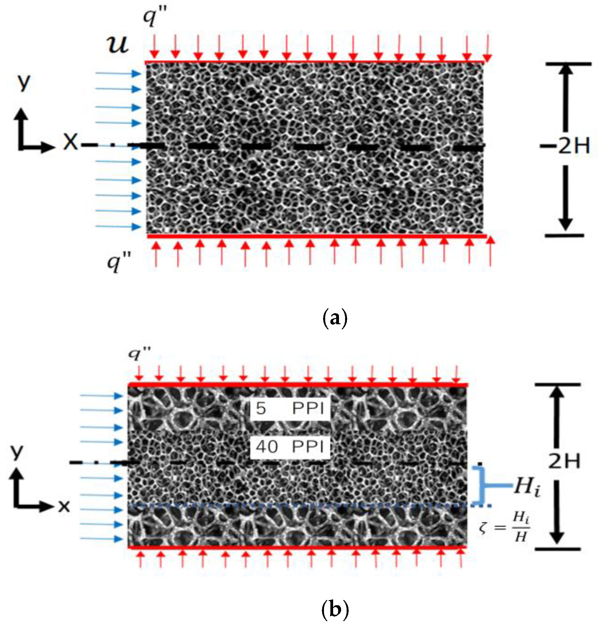
The height of the studied channel is 2H in which a laminar, steady and incompressible flow exists. Air is accepted as a working fluid and the bottom and upper walls are subjected to the identical constant heat flux. The studied cases include (a) channel filled with a uniform aluminum foam (
Figure 1a,b) that consists of two layers of aluminum foam with two different PPI values (
Figure 1b).
For the case (a), both 5 and 40 PPI metal foams are studied separately. For the case (b) which is two-layer metal foams, only one possibility which is 5 PPI for outer and 40 PPI for inner (core region) regions is studied. The ratio of layers thickness (i.e., inner layer thickness to the channel height) is shown by
(i.e.,
, see
Figure 1b). The value of
is also changed to analyze the effect of layer thickness on thermal performance of the channel with double-layer metal foam. The heat and fluid flows are fully developed in the channel and the thermal properties of both solid and fluid phases are constant. It is assumed that radiation and gravity effects do not affect the heat transfer. No viscous dissipation or heat generation exists. Furthermore, no slip of velocity and a continuous heat flux with single temperature at the interface between the layers exist. The porosity of both layers is 0.9 while the pore size changes. It should be mentioned that the location of the origin is different for the two-layer case (i.e., case (b)) as can be seen from
Figure 1. For two metal foam layers, the location of the origin is located at the interface to reduce the size of the equation. The thermal conductivity of aluminum is taken as 152 W/mK. The air density, dynamic viscosity and thermal conductivity are
,
and 0.024
, respectively.
In this study, the results are obtained for two heights of the channel to provide a more practical conclusion and include the channel Reynolds number. These channels are named as short and long height channels. The abbreviations of SHC and LHC stand for Short Height Channel (2H = 0.05 m) and Long Height Channel (2H = 0.10 m). The dimensionless parameters of the studied channels are given in
Table 1 which are based on the height values.
3. Heat and Fluid Flow for a Channel with Uniform Metal Foam
The heat and fluid flow in the channel is assumed to be hydro-dynamically and thermally fully developed. Thus, the temperature change of fluid and solid in the longitudinal direction is negligible compared to the transverse direction (i.e.,
and ). The volume averaged transverse velocity (i.e., ) is zero for a fully developed flow. The volume averaged and dimensionless temperature of the solid and fluid phases ( and ) do not change in x direction for fully developed heat and fluid flows. Furthermore, it is assumed that the friction and collision between the fluid and the surface of metal foam struts are sufficiently high to neglect Brinkman term since generally the surface area of a metal foam is large. The results of this study is valid if the channel length is sufficiently long and both hydro-dynamically and thermally fully developed regions occur. The presented results are valid just for the fully developed region.
3.1. Governing Equations and Boundary Conditions
The Darcy–Depuit Forchheimer equation is used to find the velocity in the channel filled with uniform metal foam.
where
and
are volume averaged velocity component in x direction and volume averaged pressure.
and
represent permeability and inertia coefficient of the aluminum foam. The dimensionless motion equation can be written as:
where the employed dimensionless parameters are dimensionless velocity, Darcy and Hagen numbers. They are defined as:
where
Da and
Hg are Darcy and
Hg numbers. The coefficient of b and G are defined as
and G
. As it was mentioned before, the flow is fully developed and the volume averaged velocity in y direction is negligible. The gradient of volume averaged temperature in transverse direction (y direction) is greater than longitudinal direction, therefore energy equation for the solid and fluid phases can be written as:
The coefficients of
,
and
are the interfacial heat transfer coefficient, effective thermal conductivity for solid and fluid phases, respectively. The correlation for calculation of value of
will be given in
Section 5. The mathematical definitions for
and
are,
where
is thermal dispersion conductivity.
is the effective porosity suggested by Kuwahara et al. [
12] to include the effect of tortuosity for the stagnant thermal conductivity. For porous media with high thermal conductivity ratio (such as aluminum foam and air), the value of
is suggested as:
After doing the necessary calculations, heat transfer equations for the solid and fluid phases can be written in dimensionless form:
The employed dimensionless parameters in the above equations are:
is dimensionless temperature and can be used for the solid or fluid phase,
is the pore-scale volumetric interfacial Nusselt number (
) and refers to the heat transfer from solid to fluid phase in pore scale and therefore
is used to make it dimensionless. The value of
can be obtained experimentally or theoretically and it depends on the flow and porous media structure.
is the channel-based volumetric interfacial heat transfer coefficient and it appears automatically by making the governing equations dimensionless. The relation between
and
is given by Equation (11). Both
and
are governing parameters for this problem. The boundary conditions for the channel are defined as:
3.2. Analytical Solution
The solution of motion equation (Equation (2)) can be found easily as:
As it was mentioned before,
Da and
Hg are Hagen and Da numbers and their definitions are given by Equation (3). The solution for energy equation is a little bit complicated. In the first step, the dimensionless solid and fluid phase equations (Equations (9) and (10)) are added to each other and the following equation is obtained.
where
and
are effective thermal conductivity of the fluid and solid phases while
is clear fluid phase thermal conductivity. By taking the integral of the above equation and applying boundary conditions presented by Equation (12), the dimensionless fluid temperature equation in terms of the dimensionless solid temperature can be obtained.
In order to find the solid and fluid temperatures independently, Equation (15) is substituted into Equation (9) and a second order ODE for the solid phase is found,
By solving this second order ordinary differential equation involving
with the boundary conditions given by Equation (12), the dimensionless temperature of solid and fluid phases can be obtained.
The constants of
a and
b are
As it was mentioned before,
and
are the effective thermal conductivity of the fluid and solid phases while
is clear fluid phase thermal conductivity, and
represents the channel-based volumetric interfacial heat transfer coefficient. The expression for
is found by substituting Equation (17) into Equation (15):
The coefficients of a and b are given by Equation (17).
3.3. Channel Nusselt Number
Nusselt number in this study is defined according to the difference of the wall and fluid bulk temperatures, then
and
are heat flux at the wall, interfacial heat transfer coefficient between the wall and fluid phase, wall temperature and bulk fluid temperature, respectively. Using dimensionless temperature given by Equation (11), channel Nusselt number is obtained in terms of bulk temperature:
Bulk temperature is found by integrating fluid temperature expression given by Equation (19). It should be mentioned that
is channel Nusselt number which is completely different than
and
defined by Equation (11). It refers to the heat transfer from the wall of the channel to the fluid and it is analytically found from the obtained fluid temperature expression. The channel Nusselt number is found as:
The coefficients of a and b are defined by Equation (17).
4. Heat and Fluid Flow for a Channel with Two-Layer Metal Foams
4.1. Governing Equations and Boundary Conditions
For a channel filled with a double-layer aluminum foam, there are two regions called as inner (core) and outer regions. In this study, Darcy–Forchheimer equations are solved separately for the inner and outer regions, while the pressure drop in flow direction is identical for the both regions.
where
and
are the volume averaged velocities in the inner and outer regions, as shown in
Figure 2.
and
show the permeability of the inner and outer layers. Similarly,
and
are defined as
and
, respectively. The following dimensionless parameters which are Darcy and Hagen numbers for inner and outer regions are used.
where
and
are Darcy and Hagen numbers for the inner region filled with 40 PPI metal foam while
and
are Darcy and Hagen numbers for outer region occupied with 5 PPI aluminum foam.
Hence, the dimensionless velocity in terms of inner and outer region Darcy and Hagen numbers can be found as:
and are dimensionless volume average velocities for the inner and outer layers.
The same energy equations, Equations (4) and (5) in dimensional form and Equations (9) and (10) in dimensionless form for single-layer metal foam are valid for the inner and outer regions. After applying necessary indices to the Equations (9) and (10), the following dimensionless forms of the energy equations for the inner and outer regions are obtained:
For inner region:
For outer region:
In the above equations,
and
are effective thermal conductivities for solid and fluid phases of inner layer while
and
are solid and fluid phases effective thermal conductivities of the outer layer. Similarly,
,
and
, represent solid and fluid dimensionless temperatures for the inner and outer layers. For more information about the above equations, the study of Cekmer [
2] can be reviewed. By considering the origin of the chosen axis, which is located at the interface of two layers, the boundary conditions for the above equations are defined as:
For outer region:
where
is the ratio of height of inner region to the channel height
=
. It should be mentioned that the values of
and
which are interface temperature for the solid and fluid phases are not known and should be found. The values of
,
,
and
can be calculated easily from Equation (25) and conservation of mass in the channel.
4.2. Analytical Solution
The energy equations for the solid and fluid phases are solved analytically for inner and outer regions by the similar method used to solve channel with uniform single metal foam. Therefore, the inner region, Equations (28) and (29) and the outer region, Equations (30) and (31) are added to each other and the following equations for inner and outer phase ae obtained.
By taking the integral of Equations (34) and (35) for two times and using the boundary conditions given by Equations (32) and (33), the temperature equations of fluid phase temperature for inner and outer region in terms of the solid temperatures can be found as:
where
and
are volume average fluid phase temperature for inner and outer regions, respectively.
and
are temperatures of the solid and fluid phases at the interface between two metal foam layers.
, and
are constants for the Equation (37) and they are found as:
As it was explained before, where
is the ratio of height of inner region to the channel height,
and
are the uniform volume average velocities for inner and outer regions. After obtaining the temperatures of fluid phase for inner and outer regions, they are substituted into the Equations (28) and (30) in order to find the ordinary differential equations for the solid phase temperatures of inner and outer regions. Hence, the second order ODE for energy equations of the solid phase for inner and outer phase can be expressed as:
and are channel-based interfacial Nusselt numbers for the inner and outer regions, respectively, and their definitions can be found by using Equation (11). Solving the above second order ordinary differential with the boundary conditions given by Equations (32) and (33) yields the temperature of solid phase. Substituting of the solid temperatures of inner and outer regions into Equations (36) and (37) yields the fluid temperature for each region. The obtained equations for the temperatures of inner and outer equations are given below:
Solid temperature for inner region:
Fluid temperature for inner region:
Solid temperature for outer region:
Fluid temperature for outer region:
where
The definitions of other coefficients are given in
Appendix A.
As seen in the analytic solutions of solid and fluid phases for inner and outer regions given in above equations (Equations (42)–(45)), the dimensionless fluid and solid temperature expressions involve the interface solid and fluid temperatures (
and
which are not known. In order to find the values of the interface temperatures, it is assumed that the heat flux is the same at the interface for the solid and fluid phases.
It should be mentioned that
and
are effective thermal conductivity of the solid phase for the outer and inner regions, respectively, while
and
are effective thermal conductivity of fluid phase for the outer and inner regions, respectively. The interface temperatures can be found by using above equations. Taking a derivative from the temperature equations of the solid and fluid phases of the inner and outer regions (Equations (42)–(45)) and substituting into the above equations yields the interface temperature for solid and fluid phases. After doing the necessary mathematical calculations, two equations with two unknowns which are
and
are obtained for the interface temperature:
where constants of
G,
H,
L,
M,
N and
P are given in the
Appendix A. The solution of Equations (49) and (50) yields the interface temperatures of solid and fluid phases as:
4.3. Channel Nusselt Number
By the same method described in
Section 3, the channel Nusselt number for the channel filled with multi-layer metal foams can also be found.
where
and
are fluid bulk temperature for inner and outer regions. The fluid bulk temperatures for inner and outer regions are given by Equations (55) and (56).
If the fluid bulk temperatures are known for inner and outer regions, the channel bulk temperatures can be easily calculated.
,
and
are fluid bulk temperature for entire cross section, fluid bulk temperature for inner and outer regions, respectively. Then, the channel-based Nusselt number is found as:
5. Averaged Transport Properties of Aluminum Foam with 5 and 40 PPI
Metal foams are produced by many manufactures in different countries. The manufacturers can configure the size of ligaments (or struts) and cells. It is possible to have two metal foams with the same porosity but different numbers of ligaments or different cell sizes. The permeability, inertia coefficient or the interfacial heat transfer coefficient of two metal foams having the same porosity can be considerably different. That is why, authors preferred to use PPI classification rather than porosity, in this study. Generally, five PPI values of metal foam exist in market: 5, 10, 20, 30 and 40 PPI. The present study is done for aluminum foams with 5 and 40 PPI in order to have maximum velocity difference between the outer and inner regions.
Our literature survey showed that many theoretical and experimental studies were performed on the determination of permeability and inertia coefficient of various metal foams. In this study, the reported values of permeability and inertia coefficient for aluminum foams with 5 and 40 PPI are collected and based on the average reported values of K and C for both pore densities of 5 and 40 PPI. The list of the reviewed studies for obtaining the average value of K and C is given in
Table 2. This table shows the name of researchers and the porosity value of the studied aluminum foam for foams with 5 and 40 PPI. All these studies were reviewed and their found values of permeability and inertia coefficient were recorded.
Figure 3 shows two charts in which the reported dimensionless permeability values with porosity for two different values of PPI are plotted. As seen, the vertical axis represents dimensionless permeability (
) and horizontal axis is the porosity.
is the pore-scale characteristic length, and it can be calculated from the following equation for open cell metal foams:
where PPI is number of pore per inch and 0.0254 represents 1 inch in SI system.
Figure 3 shows that for the same PPI value, metal foams with a wide range of porosity exist. There are large variances between reported permeability values for the same PPI. In this study, some extreme values (shown by grey points in
Figure 3) are discarded. For instance, around 87% of the dimensionless permeability values for metal foam with 40 PPI change between 0.10912 and 0.32984, while 26% are significantly out of this range. The out-of-range values are eliminated and an interval for permeability and inertia coefficient of each PPI is specified. The average of the values in the specified interval yields the practical prediction for the permeability and inertia coefficient of 5 and 40 PPI, as given in
Table 3.
Similar to the method employed for finding the average permeability values for PPI of 5 and 40, the same method is applied to determine average inertia coefficient. The variation of dimensionless inertia coefficient (
) with porosity is plotted, and similarly some values which are significantly out of the range are eliminated, and intervals for inertia coefficients of 5 and 40 PPI are suggested as shown in
Table 3. The average of the points in the interval yields the practical value for inertia coefficient of two aluminum foams of 5 and 40 PPI.
The correlation suggested by Calmidi et al. [
33] shows that Reynolds number in terms of pore diameter can be used as a characteristic length for determination of volumetric pore-scale interfacial Nusselt number.
where
is pore diameter,
is volumetric interstitial heat transfer coefficient, and
is thermal conductivity of fluid. In this study, only transverse thermal dispersion conductivity is needed since the flow is thermally and hydro-dynamically fully developed. The correlation suggested by Zhang et al. [
34] is used in this study. As can be seen, the dispersion thermal conductivity depends on the pore-based Reynolds number and porosity.
where
is the transverse thermal dispersion. In this study, the value of porosity is accepted as 0.9 (
and consequently the value of effective porosity (Equation (8)) becomes as 0.967 (
. The solid and fluid thermal conductivities are 0.024 and 152 (
, respectively. Hence the values of
and
can be obtained as 5.067 and 0.0232
The value
should be calculated from Equation (61) based on the pore-scale Reynolds number.
6. Results and Discussion
The governing equations with the given boundary conditions for the uniform and two-layer metal foams are also solved by numerical methods due to possibility that some mistakes may happen in the calculation of long derived expressions. A code based on the finite difference method was written to solve the governing equations for the single layer (Equations (1), (4) and (5)) and double layers (Equations (23) and (24), Equations (28)–(31)) and the analytical results from the given equations in this study were compared with the obtained numerical ones. An excellent agreement was observed between two results showing that the analytical method suggested in this study and the given expressions are correct.
Figure 4 shows a sample of the comparison done for the channel with
and
= 10.
6.1. Results for the Channel with Uniform Aluminum Foam
In order to find the dimensionless temperature and channel Nusselt number, the values of the interfacial Nusselt number and thermal dispersion should be known. These values can be calculated from Equations (60) and (61), respectively. The change of both interfacial Nusselt number and thermal dispersion ratio with pore-scale Reynolds number (
) are shown in
Figure 5a. As can be seen, by increasing the pore-scale Reynolds number, both the values of (
) and (
) increase. However, the rate of increase is not the same. The values of
are negligible at low
until
= 10 and then dramatically increases. Furthermore, Equation (11) shows that
(
) plays an important role in the results. In addition to the change of value of
the change of
with
should also be considered. The variations of
with
are given in
Figure 5b for both LHC and SHC. It is seen that the value of
is remarkably high for 40 PPI. Fluid in the cells of the metal foam with 40 PPI is mixed considerably and a large rate of heat from the ligaments of aluminum foam is transferred to the fluid. Hence, the temperature of solid and fluid phases might be close to each other. As expected, the value of
decreases according to a decrease in the channel height.
The dimensionless temperature profiles of the solid and fluid phases for the channel filled with 5 and 40 PPI of LHC when
= 10 are given in
Figure 6. For aluminum foam with 5 PPI, the dimensionless temperatures for the solid and fluid phases are different while the temperature profiles for the 40 PPI are almost identical. The reason for this difference is that the value of
for the channel with 40 PPI is considerably greater than the value of
for 5 PPI due to high mixing of flow (
for 5 PPI while
for 40 PPI. The strong mixing of the fluid in the porous media with 40 PPI causes the solid and fluid temperature profiles to almost overlap each other for the 40 PPI value. It should be mentioned that for
= 10, the thermal dispersion value is very small as can be seen from
Figure 5 and does not play an important role in the heat and fluid flow in the channel. The value of
= 0.0054 indicates negligible thermal dispersion effect.
The same profiles of
Figure 6 are prepared for
= 2000 and shown in
Figure 7. The temperature profiles for solid and fluid phases become closer to each other and those profiles completely overlap each other for 40 PPI. The fluid temperatures become closer to the solid temperature profile due to considerably higher velocity in the pores compared to
= 10. For 5 PPI channel, the values of interfacial Nusselt number and thermal dispersion ratio are
and
while the same values are 135,610 and 0.24 for 40 PPI, respectively. That is why, the dimensionless temperature profiles of 5 and 40 PPI for the high Reynolds number (
= 2000) are almost identical.
The changes of the channel Nusselt number with channel Reynolds number for SHC and LHC are plotted and presented in
Figure 8. There are three important results in
Figure 8: (a) for both channel heights, the thermal performance of the channel with 40 PPI is better than 5 PPI due to the higher values of
since the channel Nusselt number is higher, (b) there is considerable difference between thermal performance of 40 PPI and 5 PPI particularly in low values of
number (such as
= 100), this difference is larger for the SHC, (c) the thermal performance of the 5 PPI and 40 PPI become closer to each other by increase in
number due to the increase in
and
.
Figure 8 clearly shows that particularly for
the use of aluminum foams with 40 PPI provides better heat transfer enhancement compared to 5 PPI.
6.2. Results for the Channel with Multi-Layer Aluminum Foams
Figure 9 shows the temperature profile of solid and fluid phases in the fully developed LHC filled with two layers of 5 and 40 PPI when
. As can be seen, for the low values of
(such as
= 10), the temperatures of solid and fluid phases are close to each other for the inner layer. However, there is a considerable difference between the solid and fluid temperatures at the outer region since a metal foam with 5 PPI having a smaller value of
compared to 40 PPI is used. The value of
for inner and outer layers when
= 10 is 6593 and 524, respectively. Lower value of
in outer region causes the temperatures of solid and fluid phases become considerably different from each other. It should be mentioned that, since
is small, thermal dispersion is negligible and it does not have effect on the heat and fluid flow in the channel. For high values of
(such as
= 2000), partially the same trend can be observed. The temperature profiles of solid and fluid phases in the center region of the channel overlap each other due to high mixing of fluid in the pores of the metal foam with 40 PPI. In the outer region, although there is a difference between the temperature profiles of solid and fluid phases, this difference is considerably less than the difference observed for
= 10. The increase in the velocity at the outer region and consequently higher mixing of fluid can be the reason for the emergence of two temperature profiles in outer region. By increasing velocity at the outer region both the interfacial heat transfer coefficient and thermal dispersion strongly depends on
increases. The value of effective thermal conductivity ratio (
) for outer region when
= 10 is around 1 referring to the very small value of thermal dispersion. By increasing the Re number to 2000, the value of the effective thermal conductivity ratio (
) becomes 8.6 for the outer region representing an increase of 760%. This increase in the thermal dispersion for
= 2000 enhances heat transfer between solid and fluid phases in the outer region.
Figure 10 shows the change of channel Nusselt number with channel Reynolds number for single- and two-layer cases and different values of
.
Figure 10a refers to the change of channel Nusselt number of the channel with LHC; as it is seen, the channel with 40 PPI metal foam always has better performance compared to the single-layer channel with 5 PPI, as it was shown before. The thermal performance of two-layer metal foams is also always greater than the channel filled with single-layer metal foam with 5 PP. However, the same behavior is not seen if the thermal performance of two-layer metal foams and single-layer foam with 40 PPI is compared. The thermal performance of two-layer channel becomes better than that of the single-layer channel with 40 PPI when the effect of thermal dispersion and the interfacial Nusselt number in the outer region become significant. For instance, for
= 50, the value of
and
are 0.96 and 5382 for the channel with 40 PPI uniform metal foam and these values are 1 and 1165 for outer regions of two-layer channels, respectively. Higher
is the reason for better performance of 40 PPI with respect to the two-layer case. By increasing the Re number value from 50 to 1000, the velocity in the channel increases, however the increase in velocity is more for the outer region of the channel with two layers due to higher permeability. For
= 1000, the values of
and
are 2.8 and 4899 for outer regions of two-layer channels. Both the increase in values of
and
causes the thermal performance of two layers to become better than 40 PPI uniform metal foam. Particularly the increase in thermal dispersion of 130% plays an important role in better thermal performance of two-layer metal foams. The maximum heat transfer enhancement is observed for
which is around 10% greater than that of the uniform channel. This enhancement heat transfer will increase if the height of channel or
increases. Further increase in Reynolds number also causes the difference between the thermal performance of two layers and a uniform single layer to become larger. It should be mentioned that for low values of
(such as
= 0.25) the change of channel Nusselt number is close to the behavior of the channel with uniform 5 PPI metal foam since the thickness of metal foam with 40 PPI is smaller. Similarly, for
= 0.75, the change of
becomes more horizontal like what is observed for the channel with uniform 40 PPI metal foam.
The same comments are valid for the SHC however the critical channel Reynolds number for better thermal performance of the two-layer channel compared to the uniform single layer with 40 PPI occurs around
= 1000 (
Figure 10b). As it can be seen from
Figure 5b the difference between the
of 5 PPI and 40 PPI is very small. The increase in velocity at the outer region causes small changes in the value of
and consequently after
= 1000, the thermal performance of two-layer metal foams become better.
7. Conclusions
An analytical study on heat and fluid flow in a channel filled with aluminum foam of 5 and 40 PPI for individual cases and the combination of both of them as a two-layer case was performed. A local thermal non-equilibrium approach was employed and analytical expressions for the temperature of the solid and fluid phases and the channel Nusselt number were found successfully. Although the flow is fully developed in the present study, the results are presented in terms of channel Reynolds number to include the effect of the thermal dispersion and pore-scale interfacial Nusselt number. Based on the obtained results, following conclusions can be stated:
- -
The use of a double-layer channel increases the heat transfer rate through the channel particularly for high values of Reynolds number ( > 1000). The increase in velocity in the outer region assisted with high permeability metal foam increases thermal dispersion and the interfacial heat transfer coefficient, and consequently the heat exchange between the surface of metal foam and fluid.
- -
For the channels with uniform aluminum foam of 40 PPI, the temperatures of the solid and fluid phases are close to each other and the assumption of the local thermal equilibrium is valid even at low Reynolds numbers such as = 10. However, there is a considerable difference between the solid and fluid temperatures for the channel with 5 PPI when is low, and the assumption of local thermal equilibrium is valid only for high values of channel Reynolds number such as = 1000.
- -
For the channel with 40 PPI (small pore size), the interfacial heat transfer coefficient is sufficiently high even for low values of channel Reynolds numbers (i.e., = 10). That is why, by increasing channel Reynolds number, heat transfer does not change considerably.
- -
For the channel with two metal foam layers, the channel Nusselt number is always greater than uniform case with 5 PPI. The channel Nusselt number of the two-layer case is smaller than that of the uniform case with 40 PPI, but after a specific value of channel Reynolds number (such as = 100 for LHC), it becomes greater than the single-layer case with 40 PPI. High velocity at the outer region (due to higher permeability) causes both the thermal dispersion and interfacial heat transfer coefficient to considerably increase and it provides better thermal performance.
- -
The maximum heat transfer enhancement of the two-layer channel with respect to the channel with uniform metal foam with 40 PPI is obtained around 10% for = 2000 when half of channel is filled with 5 PPI metal foam. The effect of double-layer metal foam for enhancement of heat transfer for a long height channel is greater than that of a short height channel.
For the future study, the channel thermal performance including both the effect of pressure drop and heat transfer enhancement should also be studied particularly for high values of channel Reynolds numbers ( >> 2000).


