
Design and Thermodynamic Analysis of Waste Heat-Driven Zeolite–Water Continuous-Adsorption Refrigeration and Heat Pump System for Ships


Abstract
:1. Introduction
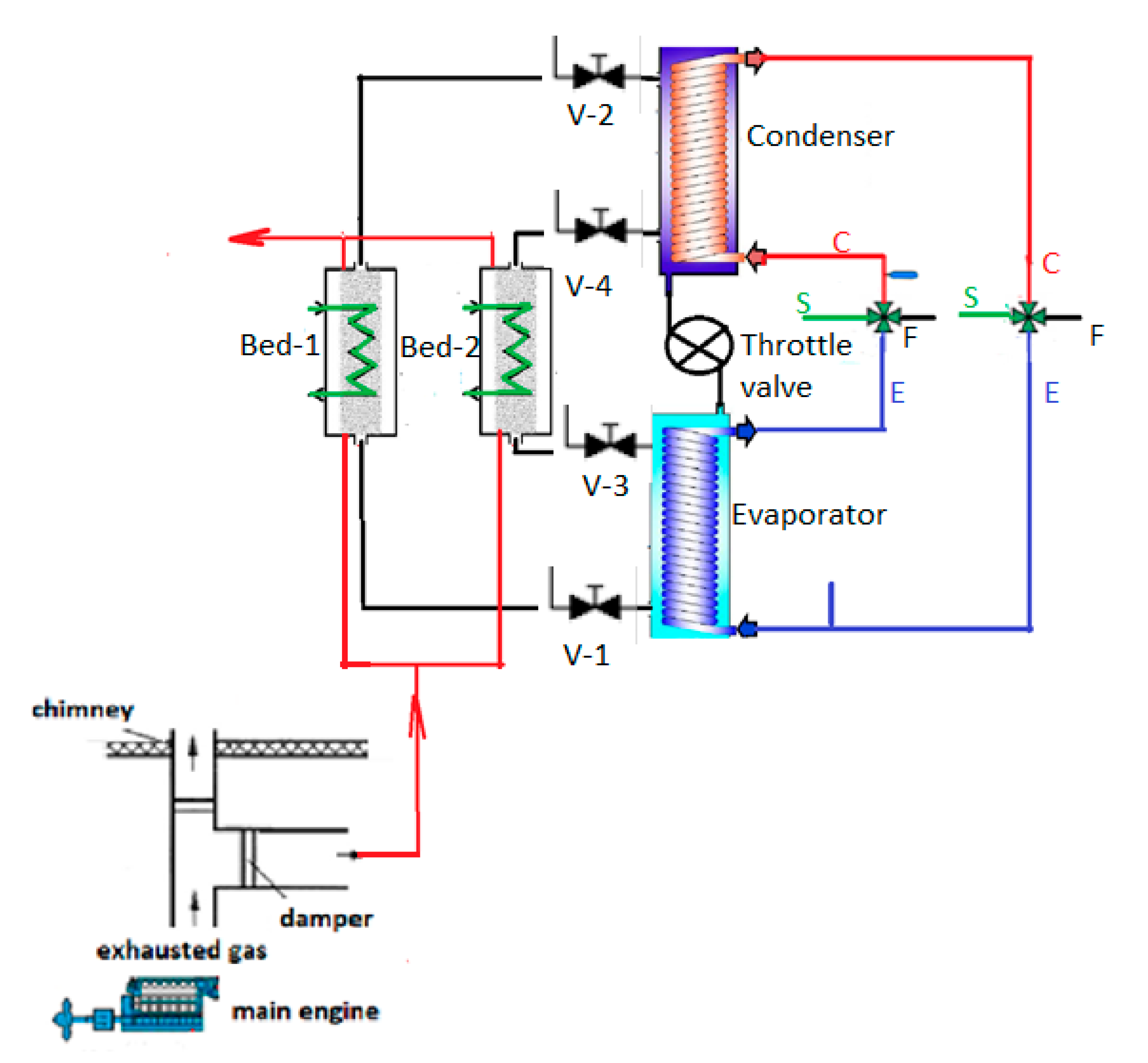
2. Refrigeration and Heat Pump System Selection and Design
3. Thermodynamic Analysis of Adsorption Refrigeration and Heat Pump System
4. Results
5. Discussion
6. Conclusions
Funding
Acknowledgments
Conflicts of Interest
Nomenclature
| C | specific heat, J/kgK |
| CEFS | condenser-evaporator-fan coil-seawater |
| COP | coefficient of performance |
| HP | heat pump |
| K | coefficient for D–A equation |
| L | latent heat, J/kg |
| M | mass, kg |
| P | pressure, Pa |
| Q | heat, kJ |
| R | universal gas constant, J/molK |
| T | temperature, K |
| SCP | specific cooling power, W/kg |
| SHP | specific heating power, W/kg |
| X | adsorption quantity, kg/kg |
| Xo | maximal adsorption rate, kg/kg |
| General Subscripts | |
| a | adsorbent |
| ad | adsorption |
| adb | adsorber |
| c | cooling |
| cond | condensation |
| d | desorption |
| e | evaporation |
| h | heating |
| Lc | liquid refrigerant |
| m | metal |
| ref | refrigerant |
| s | saturation |
References
- Ezgi, C. Design and thermodynamic analysis of an H2O–LiBr AHP system for naval surface ship application. Int. J. Refrig. 2014, 48, 153–165. [Google Scholar] [CrossRef]
- Ezgi, C.; Girgin, I. Design and Thermodynamic Analysis of a Steam Ejector Refrigeration/Heat Pump System for Naval Surface Ship Applications. Entropy 2015, 17, 8152–8173. [Google Scholar] [CrossRef] [Green Version]
- Ezgi, C.; Bayrak, S. Experimental Analysis of a Laboratory-Scale Diesel Engine Exhaust Heat–Driven Absorption Refrigeration System as a Model for Naval Surface Ship Applications. J. Ship Prod. Des. 2019, 36, 152–159. [Google Scholar] [CrossRef]
- Shu, G.; Liang, Y.; Wei, H.; Tian, H.; Zhao, J.; Liu, L.A. A review of waste heat recovery on two-stroke IC engine aboard ships. Renew. Sustain. Energy Rev. 2013, 19, 385–401. [Google Scholar] [CrossRef]
- Xu, X.; Li, Y.; Yang, S.; Chen, G. A review of fishing vessel refrigeration systems driven by exhaust heat from engines. Appl. Energy 2017, 203, 657–676. [Google Scholar]
- Qi, X.N.; Zhen, Y.L. A Model of Adsorption Icemaker on a Fishing Boat. Appl. Mech. Mater. 2012, 182–183, 1074–1078. [Google Scholar] [CrossRef]
- Wang, S.G.; Wang, R.Z. Recent developments of refrigeration technology in fishing vessels. Renew. Energy 2005, 30, 589–600. [Google Scholar] [CrossRef]
- Li, X.H.; Hou, X.H.; Zhang, X.; Yuan, Z.X. A review on development of adsorption cooling—Novel beds and advanced cycles. Energy Convers. Manag. 2015, 94, 221–232. [Google Scholar] [CrossRef]
- Demir, H.; Moghtada, M.; Ülkü, S. A review on adsorption heat pump: Problems and solutions. Renew. Sustain. Energy Rev. 2008, 12, 2381–2403. [Google Scholar]
- Wang, L.W.; Wang, R.Z.; Wu, J.Y.; Wang, K.; Wang, S.G. Adsorption ice makers for fishing boats driven by the exhaust heat from diesel engine: Choice of adsorption pair. Energy Convers. Manag. 2004, 45, 2043–2057. [Google Scholar] [CrossRef]
- Wang, L.W.; Wang, R.Z.; Wu, J.Y.; Xu, Y.X.; Wang, S.G. Design, simulation and performance of a waste heat driven adsorption ice maker for fishing boat. Energy 2006, 31, 244–259. [Google Scholar] [CrossRef]
- Wang, R.Z.; Oliveira, R.G. Adsorption refrigeration—An efficient way to make good use of waste heat and solar energy. Prog. Energy Combust. Sci. 2006, 32, 424–458. [Google Scholar] [CrossRef]
- Wang, D.C.; Li, Y.H.; Li, D.; Xia, Y.Z.; Zhang, J.P. A review on adsorption refrigeration technology and adsorption deterioration in physical adsorption systems. Renew. Sustain. Energy Rev. 2010, 14, 344–353. [Google Scholar] [CrossRef]
- Wu, W.D.; Hua, Z.; Chuan-lin, M. Performance of a modified zeolite 13X-water adsorptive cooling module powered by exhaust waste heat. Int. J. Therm. Sci. 2011, 50, 2042–2049. [Google Scholar] [CrossRef]
- Wang, R.; Liwei, W.; Jingyi, W. Adsorption Refrigeration Technology: Theory and Application; John Wiley and Sons: Singapore, 2014. [Google Scholar]
- Ouadha, A.; Youcef, El-G. Integration of an Ammonia–water Absorption Refrigeration System with a Marine Diesel Engine: A Thermodynamic Study. Procedia Comput. Sci. 2013, 19, 754–761. [Google Scholar]
- Türk Loydu. Rules for the Classification of Naval Ships. In Ship Operation Installations and Auxiliary Systems; Türk Loydu: Istanbul, Turkey, 2013. [Google Scholar]
- Khan, M.S.; Zou, R.; Yu, A. Computational simulation of air-side heat transfer and pressure drop performance in staggered mannered twisted oval tube bundle operating in crossflow. Int. J. Therm. Sci. 2020, in press. [Google Scholar]
- Wang, D.C.; Xia, Z.Z.; Wu, J.Y. Design and performance prediction of a novel zeolite–water adsorption air conditioner. Energy Convers. Manag. 2006, 47, 590–610. [Google Scholar]
- Bonaccorsi, L.; Freni, A.; Proverbio, E.; Restuccia, G.; Russo, F. Zeolite coated copper foams for heat pumping applications. Microporous Mesoporous Mater. 2006, 91, 7–14. [Google Scholar] [CrossRef]
- Tatlıer, M.; Şenatalar, A.E. The performance analysis of a solar adsorption heat pump utilizing zeolite coatings on metal supports. Chem. Eng. Commun. 2000, 180, 169–185. [Google Scholar] [CrossRef]
- Ülkü, S. Adsorption heat pumps. J. Heat Recovery Syst. 1986, 6, 277–284. [Google Scholar] [CrossRef]
- Ülkü, S. Solar Adsorption Heat Pumps, Solar Energy Utilization: Fundamentals and Applications; Martinus Nijkoff Publishers: Leiden, The Netherlands, 1987. [Google Scholar]
- Zhang L, Z.; Wang, L. Performance estimation of an adsorption cooling system for automobile waste heat recovery. Appl. Therm. Eng. 1997, 17, 1127–1139. [Google Scholar] [CrossRef]
- Zhang L, Z. Design and testing of an automobile waste heat adsorption cooling system. Appl. Therm. Eng. 2000, 20, 103–114. [Google Scholar] [CrossRef]


| Waste Heat-Driven Technology | Continuous-Adsorption Refrigeration and Heat Pump |
|---|---|
| Bed number | Two adsorbent beds |
| Type of working pairs | Zeolite–water |
| Energy source | Diesel engine exhaust heat |
| Seawater temperature | −2 °C to +32 °C |
| Chilled water outlet-inlet temperatures | 7–12 °C |
| Hot water outlet-inlet temperatures | 45–40 °C |
| Mode | Bed 1 | Bed 2 | V1 | V2 | V3 | V4 |
|---|---|---|---|---|---|---|
| Mode A—Switching | Heating | Cooling | X | X | X | X |
| Mode B—Adsorber/Desorber | Heating | Cooling | O | X | O | X |
| Mode C—Switching | Cooling | Heating | X | X | X | X |
| Mode D—Adsorber/Desorber | Cooling | Heating | X | O | X | O |
| Reference | Condensation Temperature (°C) | Evaporation Temperature (°C) | Regeneration Temperature (°C) | COP |
|---|---|---|---|---|
| This study | 50 | 4 | 160–400 | 0.1–0.38 |
| Bonarccorsi et al. [20] | 40 | 7 | 200 | 0.46 |
| Tatlıer and Şenatalar [21] | 20 | 2 | 150 | 0.3 |
| Ülkü [22] | 53 | 27 | 123 | 0.34 |
| Ülkü [23] | 52 | 25 | 200 | 0.4 |
| Zhang et al. [24] | 45 | 10 | 270–450 | 0.41 |
| Wu et al. [14] | 18 | 0.7–16.2 | 325 | 0.4 |
| Zhang et al. [25] | 30 | 10 | 255–296 | 0.38 |
| Zeolite mass (kg) | 100 |
| Metal mass of adsorbent bed (kg) | 100 |
| Average adsorption heat (kJ kg−1) | 4400 [9] |
| Specific heat of zeolite (kJ kg−1 K−1) | 0.92 [9] |
| Specific heat of water (kJ kg−1 K−1) | 4.18 |
| Specific heat of stainless steel (AISI 316; kJ kg−1 K−1) | 0.468 |
Publisher’s Note: MDPI stays neutral with regard to jurisdictional claims in published maps and institutional affiliations. |
© 2021 by the author. Licensee MDPI, Basel, Switzerland. This article is an open access article distributed under the terms and conditions of the Creative Commons Attribution (CC BY) license (http://creativecommons.org/licenses/by/4.0/).
Share and Cite
Ezgi, C. Design and Thermodynamic Analysis of Waste Heat-Driven Zeolite–Water Continuous-Adsorption Refrigeration and Heat Pump System for Ships. Energies 2021, 14, 699. https://doi.org/10.3390/en14030699
Ezgi C. Design and Thermodynamic Analysis of Waste Heat-Driven Zeolite–Water Continuous-Adsorption Refrigeration and Heat Pump System for Ships. Energies. 2021; 14(3):699. https://doi.org/10.3390/en14030699
Chicago/Turabian StyleEzgi, Cüneyt. 2021. "Design and Thermodynamic Analysis of Waste Heat-Driven Zeolite–Water Continuous-Adsorption Refrigeration and Heat Pump System for Ships" Energies 14, no. 3: 699. https://doi.org/10.3390/en14030699