Abstract
This paper presents a comparative evaluation of power electronic control approaches for vibro-acoustic noise reduction in High Rotor-Pole Switched Reluctance Machines (HR-SRM). It carries out a fundamental analysis of approaches that can be used to target acoustic noise and vibration reduction. Based on the comprehensive study, four candidates for control have been identified and applied to the HR-SRM drive to evaluate their effectiveness and identify challenges. These four methods include phase advancing, current shaping based on field reconstruction, and random hysteresis band with and without spectrum shaping. The theoretical background, implementation, and vibro-acoustic noise reduction performance of each method are presented in detail. Comparative studies from simulation and experimental measurements have been used to identify the most effective solution to acoustic noise and vibration reduction in HR-SRM configuration.
1. Introduction
Recent interest in Switched Reluctance Motors (SRMs) has grown as a low-cost replacement for permanent magnet (PM) machines and as a high-efficiency replacement for induction motors. Owing to its concentrated stator windings and absence of windings or permanent magnets on the rotor, this motor is a simple construction. They are inherently capable of low-cost manufacturing and a good competitor for high-speed applications. Furthermore, they can operate in all four quadrants and a wide speed-constant power range, which points to them as good candidates for traction applications as well.
SRM topologies with a higher number of rotor poles than stator poles, High Rotor-Pole Switched Reluctance Machines (HR-SRM), were introduced in [1,2]. These topologies offer improved torque density and quality and reduced the manufacturing cost in comparison to conventional SRM with a similar number of phases. In spite of these advantages, acoustic noise and torque ripple are still one of the main challenges of SRMs [3,4,5,6,7]. Additionally, the need for a small airgap due to a single phase excitation can lead to challenges in manufacturing.
In current literature, studies usually focused on upgrading the machine by either geometric changes or control methods. In noise, vibration, and harshness (NVH) analysis from current harmonics to rotor speed, there are several structural and operational details and parameters, that are needed to be considered. In [8], researchers have presented several experiments to identify possible acoustic noise sources for the SRM. Two control methods were proposed by current shaping and randomizing the firing angles, to reduce the acoustic noise and vibration. This study concluded that since the current shaping method would decrease the efficiency, random firing angles should be used instead. In [9] Wu and Pollock identified sources of acoustic noise and collected time domain data for phase current and vibration. It was concluded that the main source to vibration is during the turn-off process where the highest attraction (radial force) between the stator and rotor pole occurs. To reduce vibration, researchers introduced a two-stage commutation method where they introduced a zero-voltage loop to make the turn-off process in two-steps. The vibration that occurs during that process is cancelled by applying a full negative voltage after half a cycle of the vibration. This cancellation reduces the vibration and acoustic noise. In the study presented in [10], authors extended the method where a three-stage commutation at turn-off process was introduced. In a later study [11], authors showed that the active cancellation technique is weak at lower speeds, which was improved by using a speed dependent duty-cycle in zero-voltage loop. Researchers in [12] presented a comparative study by implementing five different switching control methods that have previously been introduced. Studied methods are random frequency pulse width modulation with harmonic spectrum shaping, phase advancing with fixed dwell angle, randomizing turn-off angle, and current-tail profiling. Based on experimental results, researchers concluded that combining the phase advancing with the current-tail profiling delivers the best performance in terms of the reduction of vibration and acoustic noise. It has also been shown that combining the current-tail profiling with the phase advancing leads to superior performance in terms of reduction in vibration and acoustic noise. In [13], authors introduced a two-phase excitation method for SRMs. By using the proposed approach, the excitation currents are distributed to refrain from sudden change which reduced the noise caused by excitation with decent efficiency. In [14], researchers designed a high-performance controller for the four-phase SRM drive with high power density and low noise. Snubber circuits coupled with a specific cooling system are used to improve the performance of the converter.
This exploration into the vibration and acoustic noise in SRMs has shown that a comprehensive investigation on this issue is needed, which takes into account electromagnetic and structural behavior of electric machines. At the same time, while several studies have provided promising results and analysis on conventional SRMs, there is no research for vibration and acoustic analysis in HR-SRMs, which have several differences in the electromagnetic behavior from conventional topologies. Therefore, there is a need for a comprehensive analysis for acoustic noise and vibration profile in HR-SRMs. This paper presents comparative evaluation of four power electronic control approaches for vibro-acoustic noise reduction in HR-SRM. The fundamentals of NVH analysis are presented in Section 2. Section 3 reviews the power electronic control methods for NVH mitigation and discusses the methods considered in the comparison. Details of the experimental setup and FEA (Finite Element Analysis) models are presented in Section 4. Finally, the impact of the considered methods on the NVH performance is discussed in Section 5.
2. Fundamentals of NVH
Sources of acoustic noise in electric machines can be classified as magnetic, mechanical, electronic and aerodynamic sources. Among these, acoustic noise produced by an SRM is directly related to the radial magnetic forces which generate radial vibration of the stator [10]. A Maxwell stress tensor is commonly used to calculate electromagnetic force as given in Equation (1).
where Bn and Bt are the radial and tangential flux density, respectively. The first term represents the radial force distribution on the enclosing surface. The second term represents the circumferential component of the force distribution. In the FEA model, radial force calculation is integrated on the edge of stator pole tips to obtain the total force acting on each edge. In Figure 1, a radial force map of HR-SRM is provided with respect to rotor position and current.
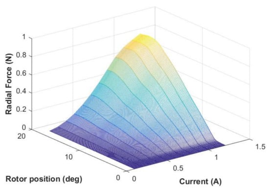
Figure 1.
Normalized radial force map of High Rotor-Pole Switched Reluctance Machines (HR-SRM) with respect to rotor position and current.
The magnetic flux across the air gap produces radial force which excites several mode shapes. Each mode shape has its own natural frequency which is determined by the geometry and material of the electric machine [15,16]. Highest vibration and noise peaks occur in an SRM when the harmonic components of the radial forces match one of the natural frequencies of the structure [17]. Authors in [15,16] have also presented an analytical study of the root causes of the noise and vibration, and a comprehensive research was provided including both power electronics and structural solutions.
From a vibration perspective, modal analysis is crucial in identifying the critical modes so that the resonance modes of the machine can be avoided during operation. This necessitates sources from having drastically large vibration and acoustic peaks specifically at natural frequencies of the body. Several studies have focused on predicting natural frequency either analytically as studied in [17,18,19,20,21,22] or by using experimental verification with hammer [23] or pulse tests [10]. In a finite element (FE) method, the deformation is calculated at each node of the meshes. The vibration equation becomes:
where, [M], [C], and [K] are the mass, damping and stiffness matrices, respectively; {x(t)}, {w(t)}, {a(t)} are the displacement, velocity, and acceleration vectors. {F(t)} is the load vector. Using FEA, harmonic response analysis can be with one model over different time steps to solve the system with simultaneous equations directly using sparse matrix solver. The full harmonic method is easy to use and applicable for all types of loads and supports. Physical preference of mesh property is chosen as mechanical for the vibration mode shape, with the relevance value set between 0–20. The advanced global sizing function is defined as curvature, which indicates that the mesh size is created by the curvature in the stator model. The patch conforming mesh method is used to ensure a high-quality surface mesh and accuracy.
Acoustic noise can be estimated though either numerical method or analytical method based on the electromagnetic and structure vibration analysis. The FE method is widely used though FEA software. [24,25,26] demonstrated the theories and formulations of the FE method. An analytical method is easier to implement with lower computational cost compared with numerical method. [27,28,29] provided analytical expressions to predict acoustic noise of SRM. The sound pressure level (SPL) can be evaluated by (3).
where is the radial sound power given by,
where the reference sound power , and are the air density and sound speed in ambient air, respectively, is angular frequency, is the radial vibration displacement, is the modal radiation efficiency, and is the outer surface of the stator.
3. Power Electronic Control and NVH in SRMs
Vibration and acoustic noise of SRM can be mitigated by mechanical and electrical method. Authors in [30] explored the principles of noise reduction while mounting and identified effective noise control methods for specific noises source in electric motor. Studies have shown that the vibration and acoustic noise of SRM can be reduced by skewing the stator and/or rotor tooth [31,32,33,34,35] and reshaping the structure of the motor [36,37]. Compared with geometry optimization, power electric control is easier to achieve without increasing industry cost.
In literature, several publications have addressed the issue of acoustic noise and vibration in SRM drives [38,39,40,41,42,43,44,45,46,47,48,49,50]. Researchers in [38] introduced a method to minimize vibration due to radial forces while keeping the torque within acceptable limits. The optimum turn-off angle has been selected to minimize the radial force, while the turn-on angle is selected to maximize the minimum torque. While the method does not affect the average torque and efficiency, the selection of proper turn-on angle could lead to a minor reduction in the generated torque since the turn-off has been fixed. In [39], a different method for noise reduction of SRM is proposed. It uses an optimal trajectory based on the variation of control current angles, which was achieved through a first order sliding mode controller. Even though it shows promising results on reducing the vibration, it does not take into account any other objectives as average torque or efficiency. Researchers in [40] presented an improved control method of variable turn-off angle based on vibration property. The control strategy is coupled with the electromagnetic and mechanical modeling to further mitigate the vibration of SRM. Results show substantial reduction in vibration energy. Nevertheless, this method was introduced with a pulse width modulated (PWM) technique only; there is not enough information to say if the method itself is successful without the PWM control. The paper [41] created an analytical method to optimize the turn-off angle on-line. The reduction of torque ripple led to a subsequent decrease in acoustic noise. The concept is applicable to the full wave mode and the chopping mode. Results show a decrease in noise; however, this method only considers torque ripple minimization. This research also did not present any information on the effect on radial forces and audible motor noise. Fuzzy logic methods were proposed for turn-off angle compensation to reduce torque ripple [42]. The turn-off angle was varied as a function of speed and current. Satisfying results on torque ripple minimization are achieved. Unfortunately, it is useful only for low-speed applications, where promising results on torque ripple minimization was accomplished. This research does not present any information or foresight for high-speed applications and effects on radial forces. Strategies for random change of switching angles were evaluated in [43]. The impact on noise behavior is evaluated by the surface normal velocity and the psychoacoustic indicators. Random change of turn-on angle and constant conduction angle showed decrease in surface normal velocity. However, surface normal velocity is used as measure of success, radial forces and acoustic sound pressure needs to be provided in order to validate its effectiveness in reducing acoustic noise.
This section presents an evaluation of four key power electronics switching methods, including phase advancing, current shaping based on field reconstruction, and random hysteresis band with and without spectrum shaping.
3.1. Phase Advancing Approach
A phase advancing approach relies on the advance shifting of turn-on and turn-off angle to decrease the high radial attractive force () that occurs at the aligned position. A multi-optimization approach can be implemented such that, optimum search looks for the firing angle pair that minimizes the radial force, while keeping the average torque various in a small range. The optimization routine is presented in Figure 2; the angle is updated by 1° at each step to provide programmable results for hardware implementation. First turn-off angle () was fixed and by initializing a turn-on angle () by degree, optimization was carried out for turn-on angle to achieve the desired torque (). Once optimum was found, it was fixed at that value and search for optimum starts for minimum radial force. Highest vibration occurs at the commutation; therefore, in the proposed method, optimum turn-off angle is selected to minimize the radial force, while turn-on angle is selected to maximize the minimum torque.
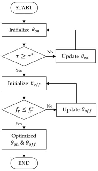
Figure 2.
Flowchart for implemented phase advancing method.
This method has an advantage, providing multi-objective optimization, maintaining the desired power level; however, it also has shortcomings, such as high torque ripple.
3.2. Current Shaping Based on Field Reconstruction Approach
The field reconstruction method (FRM) is an approach that uses a set of electromagnetic field solutions to construct basis functions for obtaining the magnetic flux densities. After determining the basic functions, the electromagnetic flux density for any condition of rotor position or excitation can be reconstructed [44]. FRM has been developed for several types of machines, including permanent magnet synchronous machines (PMSM), induction machines (IM), and SRM. This technique has showed successful results in torque ripple minimization and electromagnetic vibration calculation [45].
FRM depends on recreating machine behaviors by using flux snapshots of the machine. Along the circular contour defined in the middle of the airgap, a flux density component is calculated by the FEA method in both radial () and tangential () directions. Since symmetrical lamination is assumed, the flux density and force component in the axial direction are zero (. Once the flux density components are available, the force density on the contour in the middle of the airgap can be calculated by the MST method. By using Equation (5), radial () and tangential () force densities can be obtained, where is the permeability of air.
The formulation of the basis function of FRM for the local region is a critical step [44,45] towards predicting magnetic fields for any stator excitation at any position over a circular contour located in the middle of airgap, which uses magnetic snapshots. For SRM, radial and tangential basis functions and are defined as follows for any arbitrary current () and rotor position () [29].
The computation of basic functions depends on a truncated Fourier series expansion for each point discretized on the contour. Higher resolution can be obtained with discretizing more points. The simulation process of the conventional field-based methods such as FEA is time consuming and has higher requirements on computer performance. Limited number of FEA magnetic field solutions are used to create the complete a magnetic model of the SRM for implementing FRM, which makes analysis more efficient, especially for the optimization process. The flowchart of optimizing current profile with FRM is shown in Figure 3. Since the model is semi-analytical, it can greatly save the computational cost for simulation, especially for electric machine optimization.
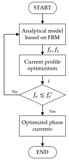
Figure 3.
Flowchart of the implemented current shaping method based on field reconstruction method (FRM).
3.3. Switching with Random Hysteresis Band (RHB)
In literature dealing with NVH, several methods for randomizing switching frequency or hysteresis band have been proposed. [46] introduced an acoustic noise mitigation control of a PMSM drive which the front-end switch mode rectifiers were applied and coupled with random switching technique. Acoustic noise profiles and reductions were presented for low frequency and high frequency operations. Further, the random switching techniques that reduces the vibration with no additional switching loss were developed and discussed [47]. The discrete switching frequencies are selected based on continuous RPWM within a uniform range of the normal switching frequency. The switching frequency harmonics is less than the conventional RPWM since fewer frequencies are chosen. Therefore, the acoustic noise generated by the inverter and randomization of the pulse position are improved. It shows a better performance on mitigating the peak noise compared with the traditional RPWM techniques. Noise and vibration due to PWM harmonic currents were considered in [48], where a variable switching frequency was used to mitigate the vibration. Active cancellation methods were proposed in [49], where a vibration mode was mitigated using an anti-phase vibration. Most researchers have focused on PMSM drives; a few random switching frequency studies have been conducted for SRM, but no literature has considered implementation the technology for an HRSRM.
In this approach, the uniform current harmonic spectrum is disturbed for HRSRM to reduces the stator vibration and speed ripple which causes acoustic noise. Figure 4 provides examples of current waveforms with different bandwidths, where is the reference current, is the output current. The hysteresis band (h) is determined by the mean value of random signal () which various with time (t) [50].
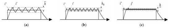
Figure 4.
Excitation profiles with random hysteresis band method: (a) ; (b) ; (c) .
The band limitation is determined by considering the acceptable switching loss and the low frequency component in the dynamic system.
3.4. Random Hysteresis Band with Spectrum Shaping (RHB-SS)
Based on the random hysteresis band, coupling with spectrum shaping can further improve the NVH behaviors of electric machines. Spectrum shaping method is based on eliminating the effect of major vibration frequency. Researchers in [50,51] developed a random band hysteresis current control method with harmonic spectrum control. To suppress the major vibration mode frequency, an estimated current () is extracted by a bandpass filter (HBP), as given in Equation (7). W is compensation command to make robust compensation for to be within the frequency range around major vibration frequency, where W = 0.99. A harmonic spectrum shaping via designing a bandpass filter as given in the following equation.
The deviation () passes through the random-band hysteresis comparator to generate the switching control signal (S). Major identified the major vibration frequency as 1.43 kHz and designed the bandpass filter with the center frequency of 1.43 kHz, quality factor Q = 1.428 and bandwidth 1.0 kHz (center frequency/Q). The current control diagram is shown Figure 5.
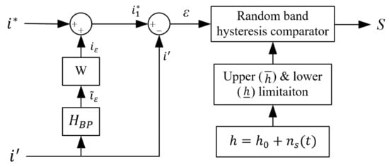
Figure 5.
Diagram of current loop with spectrum shaping.
Based on the evaluation of this approach on torque and efficiency, the effect of hysteresis band limitations and harmonic spectrum shaping at major vibration frequencies can be analyzed. By avoiding the major vibration frequencies, the acoustic noise can be decreased.
4. Experimental Setup and Validation
The target HR-SRM included a three-phase 6/10 pole configuration with a cast iron frame, the parameters are shown in Table 1. The voltage source is 480 VDC. The power electronic control strategies were implemented by using Asymmetric bridge power converters. The converter was controlled using a TMS320F28335DSP Peripheral Explorer Kit. An interface board including analog signal conditioning circuits, overrating protection circuits and encoder interface was designed to handle the necessary interface between the converter and the microprocessor. The vibration of the stator was measured by placing a PCB Piezotronics ICP accelerometer, Model 353B15, with an output sensitivity of 10 mV/g, placed behind the stator pole. A calibrated microphone PCB Piezotronics 377B02 was used to measure the emitted acoustic noise. The microphone was mounted radially at a radial distance of 1 m from the center of the machine. The outputs from the accelerometer and the microphone were recorded and analyzed by LabView interface. Figure 6 shows the HR-SRM control flow as implemented on the hardware set-up. Figure 7 shows the experimental setup used in the current study for NVH measurement.

Table 1.
Data sheet of HR-SRM.
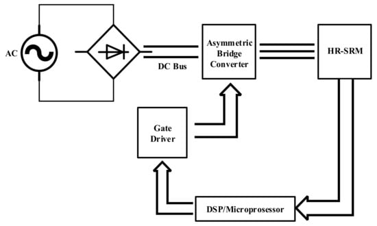
Figure 6.
Diagram of HR-SRM control.
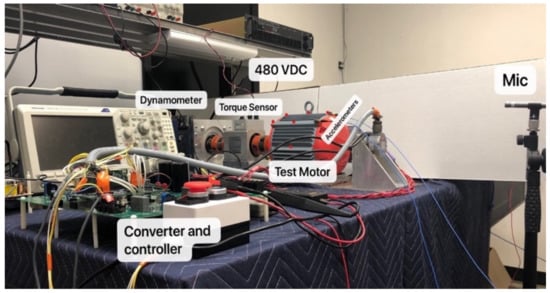
Figure 7.
Experimental set-up for power electronic control and noise, vibration, and harshness (NVH) testing.
Magnetic flux across the air gap in an electric machine develops radial force, which generates specific mode shapes, which have their own natural mode frequencies and primarily depends on machine geometry and material properties [15,16]. The highest vibration and peak noise in an SRM is observed when harmonics of the radial force coincide with natural mode frequencies to create resonance [17]. Figure 8 shows the experimental results of the vibration mode shapes and compared with the simulation results from Ansys FEA model. This experiment was done to compare the mode shapes of the experimental test with those from modal analysis generated from FEA for the same bandwidth. In this test, hammer impact test was conducted to find the natural frequencies of the test motor for bandwidth of 0–2000 Hz. Two tri-axial accelerometers were roved across 21 different points with one reference point to excite all nodes. The test was setup with fixed boundary conditions by bolting feet of the motor on test table. Supervisory control and data acquisition (SCADA) system by Siemens was used for data acquisition and LMS TestLab for data analysis and post processing. After acquiring all the Frequency Response Functions (FRFs) for all 21 selected points, the sum of all the functions was analyzed to find the natural frequencies. FRF is the ratio of output and input. In our case FRF = X/F, where x is displacement and f denote impact force. The peaks in this function denote natural frequencies. For every peak there is a specific mode shape associated with it. PolyMax module in TestLab was used to calculate the mode shapes to calibrate our FEA model. Mode shapes for the target motor up to a frequency of 2000 Hz is shown in Figure 8. This set of results was used in this study to identify frequencies that could coincide with natural mode frequencies to create resonance.
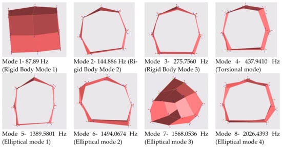
Figure 8.
Experimentally measured mode shapes of HRSRM.
The Frequency Response Function (FRF) acquired from the test were compared with the fitted curve for validation, which showed over 99% correlation among all the functions. Figure 9 shows one comparison plot for an arbitrarily chosen point. As the results show, the results of the experimental setup match results from the FEA model in ANSYS with a high degree of accuracy.
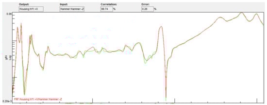
Figure 9.
Experimental Frequency Response Function vs Curve Fitting for NVH testing.
5. Results, Analysis, and Discussion
The four power electronic approaches were tested on the experimental setup described in Section 4 at 400 and 1000 rpm. Comparative results are provided to show the impact of the power electronic methods on the NVH performance of motor followed by a dedicated section discussing the results obtained.
5.1. Phase Advancing Approach
Based on the approach described in previous sections, optimized firing angles were imported to a look-up table in the experimental setup and programmed to the DSP, as shown in Figure 10. Vibration measurement from the accelerometer on the motor for time domain and frequency domain are shown in Figure 11a,b, respectively. Waveforms for sound pressure level is shown in Figure 11c and compared with results obtained from conventional excitation.
Figure 10.
Excitation current waveforms for phase advancing method.
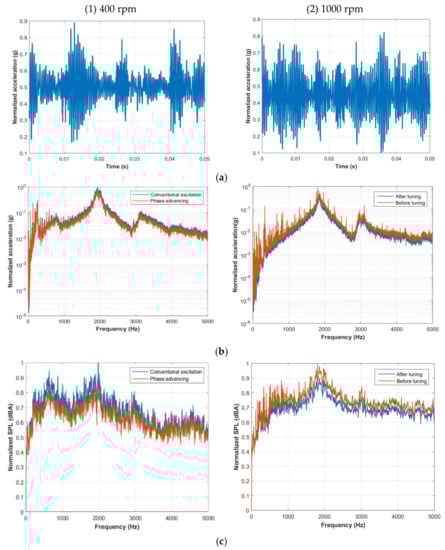
Figure 11.
NVH plots for phase advancing method; (a) Vibration profile (Time domain); (b) Vibration profile (Frequency domain); (c) Acoustic noise (Frequency domain).
This methodology is easy to implement and does not cause further switching losses. However, a lookup table for optimum firing angles is required to extend this approach to industrial applications.
5.2. Field Reconstruction Method (FRM) Approach
Similar to the phase advancing method, a look-up table was created for the optimized current waveforms that Figure 12 shows and programmed to the DSP. The NVH profiles for this test at 400 pm and 1000 rpm are shown in Figure 13.
Figure 12.
Excitation waveforms for FRM current shaping.
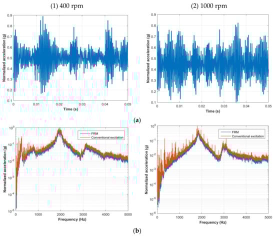
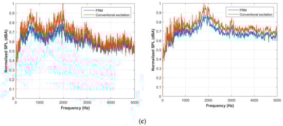
Figure 13.
NVH plots for FRM current shaping; (a) Vibration profile (Time domain); (b) Vibration profile (Frequency domain); (c) Acoustic noise (Frequency domain).
For complex profiles of the optimum current waveforms, the current tracking ability in this method was found to be limited to lower speeds owing to the available DC link voltage. This method also showed higher switching losses as compared to other methods considered. In addition, it was observed that current shaping caused a reduction in average torque.
5.3. Random Hysteresis Band (RHB) Approach
From the experiments conducted, the RHB approach showed best results when the hysteresis band width was set as 5%. In this case, peak noise was reduced 11.5% more than the 10% bandwidth and 14% more than the condition when the bandwidth is 50%. Figure 14 shows the excitation current for RHB method and the NVH profiles shows in Figure 15.
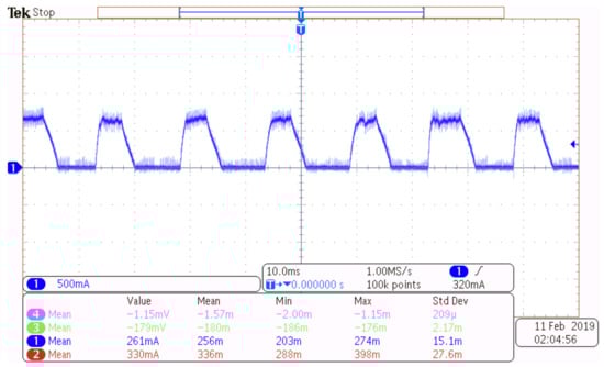
Figure 14.
Excitation current waveforms for the Random Hysteresis Band (RHB) method.
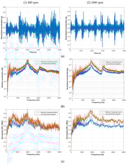
Figure 15.
NVH plots for the RHB method; (a) Vibration profile (Time domain); (b) Vibration profile (Frequency domain); (c) Acoustic noise (Frequency domain).
This approach can be simply implemented to any operation points, but similar to many power electronic switching methods, reduction in noise by hysteresis band modulation also comes with a trade-off on output torque production.
5.4. Random Hysteresis Band (RHB) Approach with Spectrum Shaping (RHB-SS)
Low frequency harmonics can be further reduced without increasing switching losses by coupling the spectrum shaping to the RHB approach. This vibration can be reduced by reducing current harmonics close to the dominant vibration frequency. The excitation current waveform is shown in Figure 16 for one operating condition, and the NVH plots are shown in Figure 17.
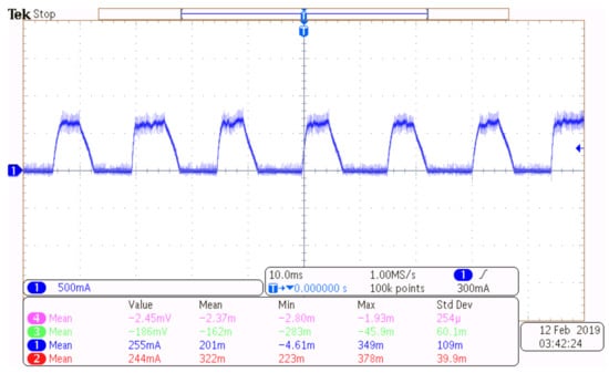
Figure 16.
Excitation current waveforms for RHB-SS method.
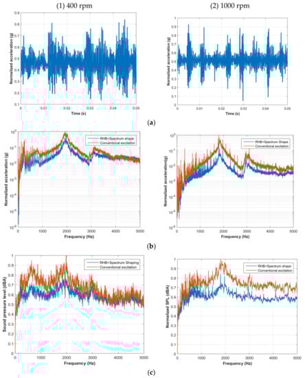
Figure 17.
NVH plots for RHB-SS method; (a) Vibration profile (Time domain); (b) Vibration profile (Frequency domain); (c) Acoustic noise (Frequency domain).
The maximum peak noise data are shown in Table 2 with a normalized value for each condition. Overall, all of the presented methods have mitigated the vibration and significantly reduced the acoustic noise.
Table 2.
Maximum peak noise with normalized values (dBA).
6. Discussion
Using the validated model described in Section 4, the FEA model was developed in Ansys and excited by current from the four power electronic control methods. The excitation current profiles for each method were the same as the experimental test. Figure 18 shows the comparison of acoustic noise profiles for each approach with the conventional excitation. A comparison of FEA results with experimental measurement confirms good accuracy for different operating conditions. This correlation between experimental and simulation results is shown in Table 3.
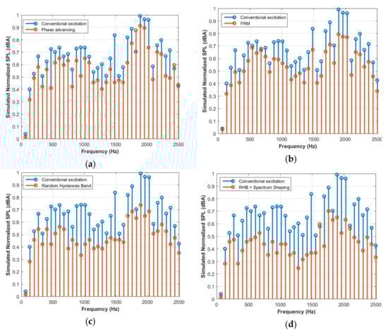
Figure 18.
Acoustic noise profile from simulation at 400 rpm (a) phase advancing method; (b) FRM current shaping showing; (c) random hysteresis band; (d) RHB+SS excitation.
Table 3.
Experimental results correlation to simulation results.
From this study, a random hysteresis band with spectrum shaping showed the best performance in reducing vibro-acoustic noise as we can see from Figure 19 and Figure 20. The phase advancing method showed high potential for reducing vibration and acoustic noise; however, it was limited in its ability to maintain the same output torque. This can be improved by adding current shaping to it, where in current shaping method based on field reconstruction provides higher reduction in noise. In order to replicate similar issues with experiments, the same output torque level was maintained during simulations. It must be noted that owing to this approximation, for further reduction or under different operation switching methodologies, performance could show further variation.
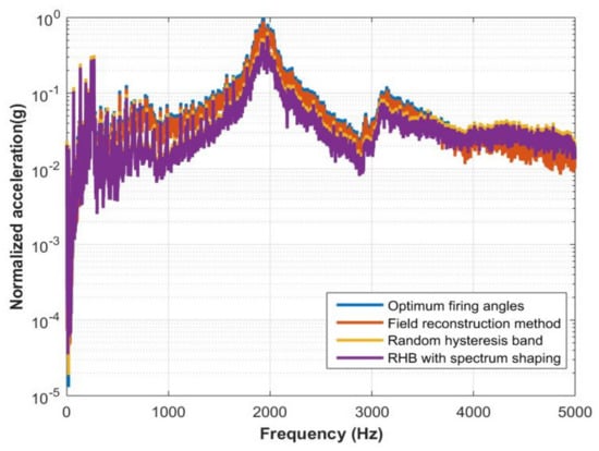
Figure 19.
Comparative measured impact of switching methods on vibration profile.
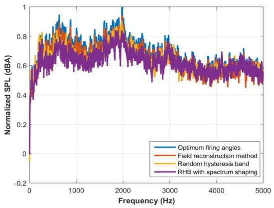
Figure 20.
Comparative measured impact of switching methods on an acoustic noise profile.
The reductions of vibration and acoustic noise for the four power electronic methods are shown in Table 4. From the vibration perspective, the phase advancing method is more effective at higher speed, and RHB method is more suitable for low-speed application. This led to the conclusion that in terms of acoustic noise, RHB-SS is the best choice for the target motor.
Table 4.
NVH reduction with power electronic methods compared to conventional excitation.
7. Conclusions
This paper analyzes and compares the effectiveness of power electronic control approaches towards reducing vibration and acoustic noise in high-rotor pole SRMs. Each approach considered in this study has specific pros and cons. The phase advancing approach is easy to implement and does not require any additional hardware, but this approach is limited in its range and flexibility. Current shaping can be very effective and target-oriented methods and approaches such as Field Reconstruction can be very effective, but these methods tend to be significantly analytical and can require additional computational capacity. A Random Hysteresis Band approach is also easy to implement with no additional need for hardware. Since it spreads the frequencies, it is also limited in the range and flexibility in control. Based on this study, random hysteresis band with spectrum shaping method was found to be most effective, since it specifically targets the dominant vibration mode for the given system. For the target motor, this approach showed a reduction of over 25% in both vibration and acoustic noise levels with minimal modification in its hardware implementation, unlike other current shaping methods. An important point to consider is that since normal and tangential flux densities have an influence on tangential and radial forces, any effort to reduce one will have consequential effect on the other. In other words, reducing radial forces would lead to a corresponding impact on generated torque as well and should be considered in any implementation.
Author Contributions
Conceptualization, M.K.; Investigation and validation, S.Y., C.C. and S.S.; Writing and editing, Z.Z. and M.S. All authors have read and agreed to the published version of the manuscript.
Funding
This work was supported in part by the U.S. National Science Foundation under Grant 1738233 and by Turntide Technologies.
Conflicts of Interest
Mahesh Krishnamurthy has worked as a consultant on the topic of Switched Reluctance Motors.
References
- Desai, P.C.; Krishnamurthy, M.; Schofield, N.; Emadi, A. Novel Switched Reluctance Machine Configuration with Higher Number of Rotor Poles than Stator Poles: Concept to Implementation. IEEE Trans. Ind. Electron. 2009, 57, 649–659. [Google Scholar] [CrossRef]
- Bilgin, B.; Emadi, A.; Krishnamurthy, M. Design Considerations for Switched Reluctance Machines with a Higher Number of Rotor Poles. IEEE Trans. Ind. Electron. 2012, 59, 3745–3756. [Google Scholar] [CrossRef]
- Ahn, J.-W.; Park, S.-J.; Lee, D.-H. Hybrid Excitation of SRM for Reduction of Vibration and Acoustic Noise. IEEE Trans. Ind. Electron. 2004, 51, 374–380. [Google Scholar] [CrossRef]
- Lin, F.-C.; Yang, S. An Approach to Producing Controlled Radial Force in a Switched Reluctance Motor. IEEE Trans. Ind. Electron. 2007, 54, 2137–2146. [Google Scholar] [CrossRef]
- Fiedler, J.O.; Kasper, K.A.; de Doncker, R.W. Calculation of the acoustic noise spectrum of SRM using modal superposition. IEEE Trans. Ind. Electron. 2010, 57, 2939–2945. [Google Scholar] [CrossRef]
- Husain, I. Minimization of torque ripple in SRM drives. IEEE Trans. Ind. Electron. 2002, 49, 28–39. [Google Scholar] [CrossRef]
- Islam, M.S.; Husain, I. Torque ripple minimization with indirect position and speed sensing for switched reluctance motors. IEEE Trans. Ind. Electron. 2000, 47, 1126–1133. [Google Scholar] [CrossRef]
- Cameron, D.E.; Lang, J.H.; Umans, S.D. The origin and reduction of acoustic noise in doubly salient variable-reluctance motors. IEEE Trans. Ind. Appl. 1992, 28, 1250–1255. [Google Scholar] [CrossRef]
- Wu, C.; Pollock, C. Analysis and reduction of vibration and acoustic noise in the switched reluctance drive. IEEE Trans. Ind. Appl. 1995, 31, 91–98. [Google Scholar] [CrossRef]
- Pollock, C.; Wu, C. Acoustic noise cancellation techniques for switched reluctance drives. IEEE Trans. Ind. Appl. 2002, 33, 477–484. [Google Scholar] [CrossRef]
- Michaelides, A.; Pollock, C. Reduction of noise and vibration in switched reluctance motors: New aspects. In Proceedings of the IAS ‘96. Conference Record of the 1996 IEEE Industry Applications Conference Thirty-First IAS Annual Meeting, San Diego, CA, USA, 6–10 October 1996; pp. 771–778. [Google Scholar]
- Chai, J.; Lin, Y.; Liaw, C. Comparative study of switching controls in vibration and acoustic noise reductions for switched reluctance motor. IEE Proc. Electr. Power Appl. 2006, 153, 348–360. [Google Scholar] [CrossRef]
- Ahn, J.-W.; Oh, S.-G.; Moon, J.-W.; Hwang, Y.-M. A three-phase switched reluctance motor with two-phase excitation. IEEE Trans. Ind. Appl. 1999, 35, 1067–1075. [Google Scholar] [CrossRef]
- Wang, S.; Zhan, Q.; Ma, Z.; Zhou, L. Implementation of a 50-kW four-phase switched reluctance motor drive system for hybrid electric vehicle. IEEE Trans. Magn. 2005, 41, 501–504. [Google Scholar] [CrossRef]
- Timar, P.L. Noise and Vibration of Electrical Machines; Elsevier: Amsterdam, The Netherlands, 1989. [Google Scholar]
- Yang, S.J. Low-Noise Electrical Motors; Clarendon Press: Oxford, UK, 1981. [Google Scholar]
- Colby, R.S.; Mottier, F.M.; Miller, T.J.E. Vibration modes and acoustic noise in a four-phase switched reluctance motor. IEEE Trans. Ind. Appl. 1996, 32, 1357–1364. [Google Scholar] [CrossRef]
- Leissa, A.W. Vibration of Shells, Scientific and Technical Information Office National Aeronautics and Space Administration; NASA: Washington, DC, USA, 1973. [Google Scholar]
- Srinivasan, R.; Sankaran, S. Vibration of cantilever cylindrical shells. J. Sound Vib. 1975, 40, 425–430. [Google Scholar] [CrossRef]
- Warburton, B.G. Vibration of thin cylindrical shells. J. Mech. Eng. Sci. 1965, 7, 399–407. [Google Scholar] [CrossRef]
- Al-Najafi, A.M.J.; Warburton, B.G. Free vibration of ring-stiffened cylindrical shells. J. Sound Vib. 1970, 13, 9–25. [Google Scholar]
- Chen, J.C.; Babcock, C.D. Nonlinear vibration of cylindrical shells. Am. Inst. Aeronaut. Astronaut. J. 1975, 13, 868–876. [Google Scholar] [CrossRef]
- Tang, Z.; Pillay, P.; Omekanda, A.M. Vibration prediction in switched reluctance motors with transfer function identification from shaker and force hammer tests. IEEE Trans. Ind. Appl. 2003, 39, 978–985. [Google Scholar] [CrossRef]
- Hunt, J.T.; Knittel, M.R.; Barach, D. Finite element approach to acoustic radiation from elastic structures. J. Acoust. Soc. Am. 1974, 55, 269. [Google Scholar] [CrossRef]
- Everstine, G. Finite element formulatons of structural acoustics problems. Comput. Struct. 1997, 65, 307–321. [Google Scholar] [CrossRef]
- Kagawa, Y.; Yamabuchi, T.; Sugihara, K.; Shindou, T. A finite element approach to a coupled structural-acoustic radiation system with application to loudspeaker characteristic calculation. J. Sound Vib. 1980, 69, 229–243. [Google Scholar] [CrossRef]
- Husain, O.; Anwar, M. Radial force calculation and acoustic noise prediction in switched reluctance machines. IEEE Trans. Ind. Appl. 2000, 36, 1589–1597. [Google Scholar] [CrossRef]
- Lecointe, J.; Romary, R.; Brudny, J.-F.; McClelland, M. Analysis and active reduction of vibration and acoustic noise in the switched reluctance motor. IEE Proc. Electr. Power Appl. 2004, 151, 725. [Google Scholar] [CrossRef]
- Callegaro, A.D.; Liang, J.; Jiang, J.W.; Bilgin, B.; Emadi, A. Radial Force Density Analysis of Switched Reluctance Machines: The Source of Acoustic Noise. IEEE Trans. Transp. Electrif. 2019, 5, 93–106. [Google Scholar] [CrossRef]
- Gieras, J.F.; Wang, C.; Lai, J.C. Noise of Polyphase Electric Motors; CRC Press: Boca Raton, FL, USA, 2018. [Google Scholar]
- Yasa, Y.; Elamin, M.; Sozer, Y.; Kutz, J.; Tylenda, J.S.; Wright, R.L. Acoustic noise mitigation for high pole count switched reluctance machines through skewing method with multiphysics FEA simulations. In Proceedings of the 2017 IEEE Energy Conversion Congress and Exposition (ECCE), Cincinnati, OH, USA, 1–5 October 2017; pp. 738–744. [Google Scholar]
- Zhang, H. Radial force reduction for switched reluctance motor with skewed slot structure based on FEM. J. Sci. Ind. Res. 2010, 69, 594–599. [Google Scholar]
- Li, Y.; Mi, C. Doubly-Salient Permanent-Magnet Machine with Skewed Rotor and Six-State Commutating Mode. IEEE Trans. Magn. 2006, 43, 3623–3629. [Google Scholar] [CrossRef]
- Yang, H.-Y.; Lim, Y.-C.; Kim, H.-C. Acoustic Noise/Vibration Reduction of a Single-Phase SRM Using Skewed Stator and Rotor. IEEE Trans. Ind. Electron. 2012, 60, 4292–4300. [Google Scholar] [CrossRef]
- Gan, C.; Wu, J.; Shen, M.; Yang, S.; Hu, Y.; Cao, W. Investigation of Skewing Effects on the Vibration Reduction of Three-Phase Switched Reluctance Motors. IEEE Trans. Magn. 2015, 51, 1–9. [Google Scholar] [CrossRef]
- Kiyota, K.; Kakishima, T.; Chiba, A.; Rahman, M.A. Cylindrical Rotor Design for Acoustic Noise and Windage Loss Reduction in Switched Reluctance Motor for HEV Applications. IEEE Trans. Ind. Appl. 2016, 52, 154–162. [Google Scholar] [CrossRef]
- Choi, Y.K.; Yoon, H.S.; Koh, C.S. Pole-Shape Optimization of a Switched-Reluctance Motor for Torque Ripple Reduction. IEEE Trans. Magn. 2007, 43, 1797–1800. [Google Scholar] [CrossRef]
- Fahimi, B.; Suresh, G.; Rahman, K.; Ehsani, M. Mitigation of acoustic noise and vibration in switched reluctance motor drive using neural network based current profiling. In Proceedings of the Conference Record of 1998 IEEE Industry Applications Conference. Thirty-Third IAS Annual Meeting (Cat. No.98CH36242), St. Louis, MO, USA, 12–15 October 1998. [Google Scholar]
- Boukhobza, T.; Gabsi, M.; Grioni, B. Random variation of control angles, reduction of SRM vibrations. IEEE Trans. Magn. 2001, 43. [Google Scholar] [CrossRef]
- Zhang, M.; Mininger, X.; Bahri, I.; Vlad, C. Improvement of the variable turn-off angle control for SRM regarding vibration reduction. IEEE Int. Electr. Mach. Drives Conf. 2017. [Google Scholar] [CrossRef]
- Orthmann, R.; Schoner, H.P. Turn-off angle control of switched reluctance motors for optimum torque output. Eur. Conf. Power Electron. Appl. 1993, 6, 20–25. [Google Scholar]
- Rodrigues, M.; Branco, P.J.C.; Suemitsu, W. Fuzzy logic torque ripple reduction by turn-off angle compensation for switched reluctance motors. IEEE Trans. Ind. Electron. 2001, 48, 711–715. [Google Scholar] [CrossRef]
- Scharfenstein, D.; Burkhart, B.; De Doncker, R.W.; Daniel, S. Influence of an FPGA-based switching angle dithering on acoustics in single-pulse controlled switched reluctance machines. In Proceedings of the 2015 IEEE 11th International Conference on Power Electronics and Drive Systems, Sydney, Australia, 9–12 June 2015; pp. 754–761. [Google Scholar]
- Lin, C.; Fahimi, B. Reduction of torque ripple in Switched Reluctance Motor drives using Field Reconstruction Method. In Proceedings of the 2011 IEEE Vehicle Power and Propulsion Conference, Chicago, IL, USA, 6–9 September 2011; pp. 1–5. [Google Scholar]
- Zhu, W.; Fahimi, B.; Pekarek, S. A Field Reconstruction Method for Optimal Excitation of Permanent Magnet Synchronous Machines. IEEE Trans. Energy Convers. 2006, 21, 305–313. [Google Scholar] [CrossRef]
- Chai, J.-Y.; Ho, Y.-H.; Chang, Y.-C.; Liaw, C.-M. On Acoustic-Noise-Reduction Control Using Random Switching Technique for Switch-Mode Rectifiers in PMSM Drive. IEEE Trans. Ind. Electron. 2008, 55, 1295–1309. [Google Scholar] [CrossRef]
- Bhattacharya, S.; Mascarella, D.; Joos, G.; Moschopoulos, G. A discrete random PWM technique for acoustic noise reduction in electric traction drives. In Proceedings of the 2015 IEEE Energy Conversion Congress and Exposition (ECCE), Montreal, QC, Canada, 20–24 September 2015; pp. 6811–6817. [Google Scholar]
- Yang, Z.; Yaman, S.; Krishnamurthy, M. Mitigation of electromagnetic vibration in PMSM: A rotor position related variable switching frequency technique. In Proceedings of the 2017 IEEE Transportation Electrification Conference and Expo (ITEC), Chicago, IL, USA, 22–24 June 2017; pp. 448–452. [Google Scholar]
- Long, S.; Zhu, Z.; Howe, D. Effectiveness of Active Noise and Vibration Cancellation for Switched Reluctance Machines Operating Under Alternative Control Strategies. IEEE Trans. Energy Convers. 2005, 20, 792–801. [Google Scholar] [CrossRef]
- Chai, J.-Y.; Chang, Y.-C.; Liaw, C.-M. On the Switched-Reluctance Motor Drive with Three-Phase Single-Switch Switch-Mode Rectifier Front-End. IEEE Trans. Power Electron. 2009, 25, 1135–1148. [Google Scholar] [CrossRef]
- Kang, B.; Liaw, C. Random hysteresis PWM inverter with robust spectrum shaping. IEEE Trans. Aerosp. Electron. Syst. 2001, 37, 619–629. [Google Scholar] [CrossRef]


Publisher’s Note: MDPI stays neutral with regard to jurisdictional claims in published maps and institutional affiliations. |
© 2021 by the authors. Licensee MDPI, Basel, Switzerland. This article is an open access article distributed under the terms and conditions of the Creative Commons Attribution (CC BY) license (http://creativecommons.org/licenses/by/4.0/).