Abstract
We developed an International Electrotechnical Commission (IEC) 61850-based centralized protection scheme to prevent single line-to-ground (SLG) faults in the feeders and busbars of ungrounded distribution systems. Each feeder intelligent electronic device (IED) measures its zero-sequence current and voltage signals and periodically transmits zero-sequence phasors to a central IED via a Generic Oriented Object Substation Event message. Using the zero-sequence phasors, the central IED detects SLG faults in feeders and busbars. To achieve centralized protection, angle differences between the zero-sequence currents and voltage phasors are exploited, and their calculation compensates for data desynchronization. The feeder IEDs were implemented using the MMS-EASE Lite library, while the transmitted zero-sequence phasors were calculated based on fault signals simulated by Power System Computer Aided Design / Electro-Magnetic Transient Design and Control (PSCAD/EMTDC). The central IED determined if the SLG fault was in a feeder or busbar by aggregating and analyzing the zero-sequence phasors received from the feeder IEDs. The results confirmed the validity and efficiency of our centralized protection scheme.
1. Introduction
Ungrounded distribution systems rely on the natural capacitance between the lines and the ground. Consequently, single line-to-ground (SLG) faults do not cause high current flow, and rapid isolation of the faulted section is not essential. Therefore, ungrounded distribution systems are preferred in industrial plants where high service continuity minimizes the interruption of expensive production processes. However, during an SLG fault, the line-to-ground voltage of non-faulty regions increases to match the line-to-line voltage, which can cause a second SLG fault at the weakest insulation point of the system [1]. The second SLG fault will usually cause a high fault current; therefore, detection and repair of the first SLG fault is important.
The electrical devices of power systems have evolved from electromechanical relays to intelligent electronic devices (IEDs) that communicate with each other. However, this communication has rarely been exploited in protection schemes because reliable and fast operation is required when a fault occurs. Technological breakthroughs have increased the feasibility of communication-based protection schemes. The International Electrotechnical Commission (IEC) 61850 standard describes real-time communication among IEDs using Generic Oriented Object Substation Event (GOOSE) messages [2] and sampled values [3]. As the complexity of a protection system increases, its reliability decreases. With respect to the mean time between failures (MTBF), communication-based protection schemes have lower MTBF than conventional protection schemes. Instead, communication-based protection schemes have advantages to enhance the security of a protection system with the ability of more accurate fault detection. Moreover, IEC 61850 uses retransmission mechanisms for GOOSE messages. This mechanism improves the reliability of IEC 61850-based protection schemes by checking the status of IEDs and their communications continuously. Consequently, protection schemes based on IEC 61850 have been widely used in power systems [4,5,6,7,8,9,10,11,12,13,14,15,16,17,18,19,20,21,22,23,24,25,26,27,28] and expanded to protect microgrids [4,5,6] and inter-substations [7,8,9,10]. Distribution system protection schemes based on IEC 61850 are also under study [11,12,13,14,15,16,17,18].
The IEC 61850-based overcurrent principle is exploited for the busbar protection [11] and adaptive protection [12] of distribution systems. However, the use of distributed resources (DRs) may cause protective malfunctions. In reference 13, the 67/67N protection for ring systems with DRs was adapted based on IEC 61850. In reference 14, regional information was utilized to mitigate the negative effect of DRs on protection performance and improve fault tolerance. Current differential principles with higher sensitivity [15] and current differential schemes as the device-failure-related backup protection [16] provide more effective protection for distribution systems. However, current differential protection is confronted with the challenges of data synchronization. The communication-assisted protection scheme described in reference 17 solves this problem by compensating for propagation delay without the need for an external clock. In reference 18, the fault detection times of protective IEDs were improved in various substations based on IEC 61850.
We developed a centralized protection scheme based on IEC 61850 to protect SLG faults in ungrounded distribution systems. SLG faults can be detected in both busbars and feeders, even if the IEC 61850 data are desynchronized. The remainder of this paper is organized as follows. Section 2 describes the characteristics of SLG faults in ungrounded distribution systems. Section 3 discusses centralized protection based on IEC 8150, including how to determine threshold values for SLG faults in feeders and busbars. The communication configuration, and the protective algorithm implemented in the central IED, are also covered. The performance of the centralized protection scheme is evaluated using Power System Computer Aided Design / Electro-Magnetic Transient Design and Control (PSCAD/EMTDC) in Section 4. Section 5 provides our concluding remarks.
2. SLG Faults in an Ungrounded Distribution System
The ungrounded distribution system under study operates radially; four feeders are supplied by a Y/Δ step-down transformer (Figure 1). A ground potential transformer (GPT) is installed at the 22 kV busbar to measure the zero-sequence voltage. The wye-connected primary windings of the GPT are solidly grounded by a current-limiting resistor (CLR) connected across the broken delta of the tertiary windings. The CLR provides very high-resistance grounding for ungrounded systems (of a few tens of kilo-ohms); therefore, SLG faults produce zero-sequence currents that are extremely small compared to the phase currents. Thus, it is nearly impossible to calculate zero-sequence currents from phase currents; zero-sequence current transformers (ZCTs) are commonly used to accurately measure zero-sequence currents. Table 1 summarizes the system configuration. Two different SLG faults were considered in this paper: a fault in a feeder and a fault in the 22 kV busbar. It is noted that the central protection proposed in this paper can be easily applied to other ungrounded distribution systems. The system shown in Figure 1 is just an example to explain the characteristics of SLG faults in ungrounded distribution systems.
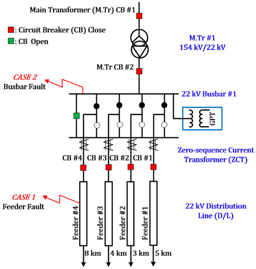
Figure 1.
The ungrounded distribution system under study.

Table 1.
System configuration.
2.1. SLG Fault in a Feeder
The angle difference between the zero-sequence voltage and current phasors is generally used to identify the faulty feeder in an ungrounded system. The zero-sequence angle difference of the mth feeder is given by:
where and are the angles of the zero-sequence current and voltage phasors at the mth feeder, respectively. Note that the angle of the zero-sequence voltage phasor should be identical at all feeders, because the GPT supplies the same zero-sequence voltage signal to each feeder IED.
Figure 2 shows the sequence networks, and their interconnections, in a case when an SLG fault developed in the fourth feeder. The notation is as follows:
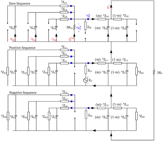
Figure 2.
Interconnections of sequence networks in the case of a single line-to-ground (SLG) fault developed in the fourth feeder.
- : Zero-sequence line impedance of the mth feeder;
- : Zero-sequence line-to-ground capacitive impedance of the mth feeder;
- : Zero-sequence load impedance of the mth feeder;
- : Zero-sequence source impedance including the transformer impedance;
- : Zero-sequence current at the CLR;
- : Zero-sequence current at the relay point of the mth feeder;
- : Zero-sequence voltage at the relay point of the mth feeder;
- : Zero-sequence current at the fault point.
Where 0 denotes the zero sequence and it is replaced with 1 and 2 to represent the positive and negative sequences, respectively.
The zero-sequence impedance of an ungrounded system is very large; therefore, the positive- and negative-sequence impedances can be ignored when considering the SLG fault in a feeder. This simplifies the sequence network, and thus the phasor diagram (Figure 3). Circuit analysis of the simplified sequence network yields the zero-sequence current at the fault point:
where the equivalent capacitive impedance of all feeders is
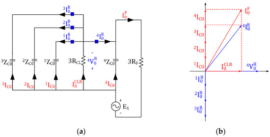
Figure 3.
Simplified sequence network and corresponding phasor diagram in the case of an SLG fault in the fourth feeder: (a) simplified sequence network; (b) corresponding phasor diagram.
In line with the current divider rule, the zero-sequence current at the relay point of the fourth feeder is:
where the equivalent capacitive impedance of the non-faulty feeders is .
As shown in Figure 3b, if a forward SLG fault develops in front of the relay point, the zero-sequence angle difference becomes between 0° and 90° depending on the size of the CLR. If a backward SLG fault develops behind the relay point, the theoretical zero-sequence angle difference becomes −90°.
2.2. SLG Fault in a 22 kV Busbar
For busbars in transmission systems, differential protection is commonly used. However, in distribution systems, overcurrent protection is considered to be adequate and thus preferred. For an ungrounded distribution system, however, neither differential nor overcurrent protection can be used to prevent busbar SLG faults because the fault current is small. A dedicated busbar protection is nonetheless required; therefore, we focused on IEC 61850-based protection. Figure 4 shows the sequence network and interconnections when an SLG fault develops in a 22 kV busbar.
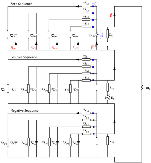
Figure 4.
Interconnections in the case of an SLG fault in a 22 kV busbar.
Similar to when an SLG faults develops in a feeder, the positive- and negative-sequence impedances can be ignored when considering an SLG fault in a busbar. This simplifies the sequence network and phasor diagram (Figure 5).
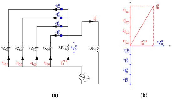
Figure 5.
Simplified sequence network and phasor diagram in the case of an SLG fault in a 22 kV busbar: (a) simplified sequence network; (b) corresponding phasor diagram.
Although the topology in Figure 5a differs from that in Figure 3a, the Thevenin equivalent circuits at the fault points, and thus also the zero-sequence currents, are identical. However, the zero-sequence current at the relay point is not the same as that of Equation (3), although it can be calculated using the current divider rule. For example, the zero-sequence current at the relay point of the fourth feeder is:
As shown in Figure 5b, if an SLG fault develops in a busbar, the zero-sequence angle differences become −90° at the relay points of all feeders; this enables identification of a busbar SLG fault.
3. IEC 61850-Based Centralized Protection
Figure 6 shows the configuration of the IEC 61850-based centralized protection scheme for ungrounded distribution systems. Each feeder IED measures the zero-sequence current and voltage signals at the relay point. After calculating the zero-sequence phasors, the IED transmits them to a central IED via a GOOSE message. The central IED identifies SLG faults based on the zero-sequence phasors. For accurate analysis, data desynchronization among feeder IEDs must be compensated for. Data desynchronization is caused by discrepancies in measurement times (i.e., when data sources update at different times) and time desynchronization (i.e., timestamp errors) [28]. Angle differences between the zero-sequence voltage phasors of feeder IEDs are used to estimate data desynchronization. This is possible because the GPT supplies the same zero-sequence voltage signal to each feeder IED (see Section 2.1). Therefore, centralized protection is based on the zero-sequence angle difference, instead of the angle itself of the zero-sequence voltage and current phasors. Data desynchronization is compensated for when the centralized protection calculates the zero-sequence angle difference.
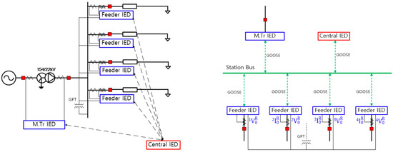
Figure 6.
Configuration of the International Electrotechnical Commission (IEC) 61850-based centralized protection scheme with intelligent electronic devices (IEDs).
3.1. Operation of the Central IED When an SLG Fault Occurs in a Feeder
If an SLG fault develops in a feeder, the central IED operates only when the following conditions are all satisfied for the mth feeder:
The zero-sequence voltage should be larger than the threshold value . Note that the zero-sequence voltage at each feeder should have the same phasor regardless of SLG fault location, because the Thevenin equivalent circuit at the CLR is identical. Below, we deal with an SLG fault in the fourth feeder; SLG faults in other feeders are handled similarly. As shown in Figure 3a, the zero-sequence voltage at the relay point is:
when the zero-sequence current at the CLR is:
Substitution of (2) into (3) yields:
Assuming that the fault resistance ranges up to 5 kΩ, it is possible to determine and using (6) and (8), respectively. The threshold value for the zero-sequence angle difference is also determined by (6) and (8). Note that the zero-sequence angle difference is independent of the fault resistance, as indicated by the relationship between and own in Figure 3b.
Although the sum of the zero-sequence currents at the relay points of non-faulty feeders is the same as the capacitive zero-sequence current at the relay point of the faulty feeder, the polarities are opposite. This is useful for determining whether the ZCT polarities are correct. For this purpose, an operator is defined as follows:
where and . Note that yields the component of orthogonal to . Therefore, the following condition should be satisfied if there is an SLG fault in the fourth feeder:
3.2. Operation of the Central IED When an SLG Fault Occurs in a Busbar
If the SLG fault is in a busbar, the central IED operates only when the following conditions are satisfied for every feeder:
The zero-sequence voltage at each feeder is identical for SLG faults with the same fault resistance; therefore, the of (5–1) is used in (11–1). As shown in Figure 5a, the zero-sequence voltage at the relay point is:
where the zero-sequence current at the CLR is:
The zero-sequence current at the relay point of the mth feeder is:
Similar to the case of an SLG fault in a feeder, assuming that the fault resistance ranges up to 5 kΩ, it is possible to determine and using (12) and (14), respectively. In addition, the threshold value for the zero-sequence angle difference can be easily found from (14); this becomes the angle of .
As shown in Figure 7, is between 0° and 90°, depending on the size of the CLR, while is −90° for all feeders.
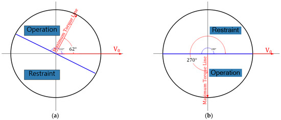
Figure 7.
Threshold values of the zero-sequence angle differences: (a) for an SLG fault in a feeder; and (b) for an SLG fault in a busbar.
3.3. Algorithm for Centralized Protection
Figure 8 shows the flowchart for centralized protection against SLG faults in a feeder and busbar. Each feeder IED periodically transmits its zero-sequence current and voltage phasors to the central IED via GOOSE messages. The central IED uses their magnitudes and angle differences to identify an SLG fault in a feeder or busbar. Data desynchronization is compensated for when the zero-sequence angle difference is calculated.
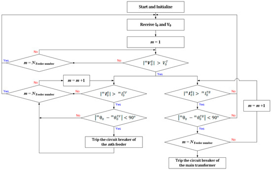
Figure 8.
Flowchart of the centralized protection scheme to prevent SLG faults.
The presence of an SLG fault is checked for each feeder sequentially. If the operating conditions given in Equation (5) are satisfied for the mth feeder, the central IED determines that an SLG fault develops in the mth feeder and then sends GOOSE messages to trip the circuit breaker of the mth feeder. As shown in Figure 8, the presence of an SLG fault in a busbar is checked independently of this process. If the operating conditions given in (11) are satisfied for every feeder, the central IED determines that an SLG fault develops in the busbar and then sends GOOSE messages to trip the circuit breaker of a main transformer.
4. Performance Evaluation
4.1. Test Environment
To determine the efficiency of the centralized protection scheme, the ungrounded distribution system shown in Figure 1 was modeled using PSCAD/EMTDC. As shown in Figure 9, the system had four feeders, each supplying a 5 MVA load (pf 0.98, delta connection). The distribution line was 20 km in total length.
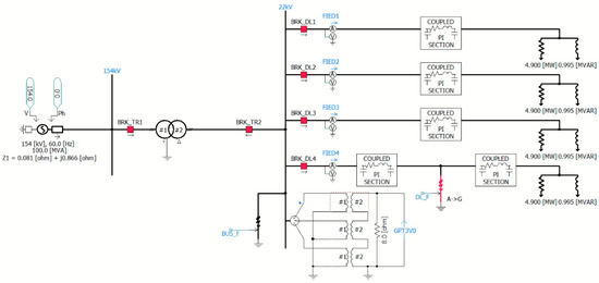
Figure 9.
Power System Computer Aided Design/Electro-Magnetic Transient Design and Control (PSCAD/EMTDC) modeling of the ungrounded distribution system.
IEC 61850-based feeder IEDs were implemented using MMS-Ease Lite Library 6.2000.2v, a commercial development tool from SISCO. As shown in Figure 10, the simulated fault signals were imported by the feeder IEDs in advance, and each feeder IED then transmitted zero-sequence phasors to the central IED every 100 ms via GOOSE messages. IEC 61850 packets, including the GOOSE messages, were monitored using IEDScout, a commercial testing tool from OMICRON. This environment was able to test the centralized protection because it is not sensitive to data desynchronization.
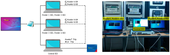
Figure 10.
The test environment for the centralized protection scheme.
4.2. Case Studies
4.2.1. SLG Faults in the Fourth Feeder
At a fault resistance of 5 kΩ, the threshold values and were set to 155.5 V and 1.555 mA using (6) and (8), respectively. The threshold value for the zero-sequence angle difference, , was set to 62.14° using both (6) and (8). In the case studies, six SLG faults (resistances of 0, 1, 2, 3, 4, and 5 kΩ) were considered. Figure 11 shows the test results for an SLG fault in the fourth feeder with a fault resistance of 0 kΩ.
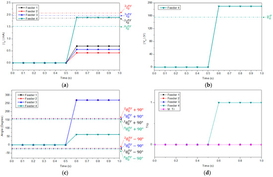
Figure 11.
Test results for SLG faults in the fourth feeder with a fault resistance of 0 kΩ. (a) Zero-sequence current. (b) Zero-sequence voltage. (c) Zero-sequence angle difference. (d) Trip signal.
All of the conditions in (5) were satisfied; the centralized protection scheme detected the fault and the central IED transmitted GOOSE messages that tripped the fourth feeder (Figure 12). Table 2 summarizes the test results according to the fault resistance. Up to a resistance of 4 kΩ, all of the conditions in (5) were satisfied for the fourth feeder. However, for a fault resistance of 5 kΩ, the measured values were the same or slightly lower than the threshold values, and the centralized protection scheme did not detect the fault. Thus, the fault resistance must be lower than a predefined value.
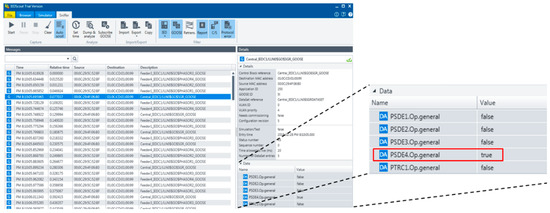
Figure 12.
Generic Oriented Object Substation Event (GOOSE) messages sent when an SLG fault developed in the fourth feeder with a fault resistance of 0 kΩ.
Table 2.
Test results for SLG faults in the fourth feeder with different fault resistances.
4.2.2. SLG Faults in a 22 kV Busbar
As mentioned in Section 3.2, was set to −90° for every feeder. At a fault resistance of 5 kΩ, the threshold value was set to 155.5 V using (12). The threshold values , , , and were set to 0.573, 0.344, 0.458, and 0.917 mA, respectively, using Equation (14).
Figure 13 shows the test results for an SLG fault in a busbar with a fault resistance of 3 kΩ. All of conditions in (11) were satisfied for every feeder, and the centralized protection scheme thus detected the SLG fault and transmitted GOOSE messages that tripped the main transformer (Figure 14).
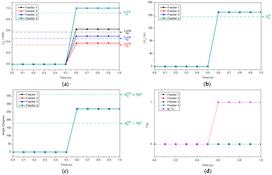
Figure 13.
Test results for a busbar SLG fault with a resistance of 3 kΩ. (a) Zero-sequence current. (b) Zero-sequence voltage. (c) Zero-sequence angle difference. (d) Trip signal.
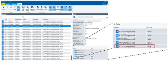
Figure 14.
GOOSE messages sent when an SLG fault developed in the busbar with a fault resistance of 3 kΩ.
Table 3 summarizes the test results for busbar SLG faults with resistances 1, 3, and 5 kΩ. All of the conditions in (11) were satisfied for every feeder when the resistances were 1 and 3 kΩ. For a fault resistance of 5 kΩ, the measured values were the same or slightly lower than the threshold values, and the centralized protection scheme did not detect the fault. To reiterate, centralized protection can detect SLG busbar faults when the fault resistance is lower than a predefined value.
Table 3.
Test results for SLG busbar faults with various resistances.
5. Conclusions
We proposed a centralized protection scheme against SLG faults in ungrounded distribution systems associated with centralized environments, such as digital substations, wherein data desynchronization occurs among IEC 61850-based IEDs. The proposed scheme detects against the SLG fault in each feeder and checks whether the ZCT polarities are correct. Particularly, in order to cope with the absence of protection against the SLG fault in a busbar, the proposed scheme provides a dedicated busbar protection with the help of centralized environments. Each feeder IED measures its zero-sequence current and voltage signals and periodically transmits zero-sequence phasors to a central IED via GOOSE messages. To detect SLG faults, the scheme analyzes the angle differences between, and magnitudes of, the zero-sequence current and voltage phasors. The zero-sequence voltage at each feeder IED should be identical; therefore, data desynchronization is compensated for when the zero-sequence angle difference is calculated.
The centralized protection was tested using IEC 61850-based IEDs and fault signals simulated by PSCAD/EMTDC. The ungrounded distribution system under study was modeled using PSCAD/EMTDC and then various cases were simulated considering fault location and fault resistance. IEC 61850-based IEDs were implemented using MMS-EASE Lite library 6.2000.2v, and the fault signals simulated by PSCAD/EMTDC were imported to the feeder IEDs. Each feeder IED transmitted its zero-sequence current and voltage phasors to the central IED every 100 ms via GOOSE messages. The central IED aggregated the zero-sequence phasors and transmitted GOOSE messages with trip signals when SLG faults were detected. The system detected SLG faults up to a fault resistance of 5 kΩ; six fault resistances were tested (0, 1, 2, 3, 4, and 5 kΩ). The scheme did not detect faults with resistances of 5 kΩ. These results demonstrated that the centralized protection scheme is useful for detecting the SLG faults in ungrounded systems when the fault resistance is lower than a pre-defined value.
Author Contributions
Conceptualization, S.-R.N. and W.-H.K.; methodology, S.-R.N., W.-H.K., S.K., S.-H.K. and N.-H.L.; supervision, S.-R.N.; validation, W.-H.K. and S.K.; writing—original draft preparation, S.-R.N. and W.-H.K.; writing—review and editing, S.K., S.-H.K. and N.-H.L. All authors have read and agreed to the published version of the manuscript.
Funding
This research was supported by the Korea Electric Power Corporation (KEPCO) (Grant number: R17XA05-2). This research was also supported by the Korea research foundation with funding from the government (Ministry of Education) in 2019 (No. NRF-2019R1F1A1059619).
Conflicts of Interest
The authors declare no conflict of interest.
References
- Nam, S.-R.; Kang, S.-H.; Ahn, S.-J.; Choi, J.-H. Single line-to-ground fault location based on unsynchronized phasors in automated ungrounded distribution systems. Electr. Power Syst. Res. 2012, 86, 151–157. [Google Scholar] [CrossRef]
- Communication Networks and Systems for Power Utility Automation—Part 8-1: Specific Communication Service Mapping (SCSM)—Mappings to MMS (ISO 9506-1 and ISO 9506-2) and to ISO/IEC 8802-3; IEC 61850-8-1 Ed.2; IEC: Geneva, Switzerland, 2011.
- Communication Networks and Systems for Power Utility Automation—Part 9-2: Specific Communication Service Mapping (SCSM)—Sampled Values over ISO/IEC 8802-3; IEC 61850-9-2 Ed.2; IEC: Geneva, Switzerland, 2011.
- Ustun, T.S.; Ozansoy, C.; Zayegh, A. Modeling of a Centralized Microgrid Protection System and Distributed Energy Resources According to IEC 61850-7-420. IEEE Trans. Power Syst. 2012, 27, 1560–1567. [Google Scholar] [CrossRef]
- Monadi, M.; Gavriluta, C.; Luna, A.; Candela, J.I.; Rodriguez, P. Centralized Protection Strategy for Medium Voltage DC Microgrids. IEEE Trans. Power Deliv. 2017, 32, 430–440. [Google Scholar] [CrossRef]
- Memon, A.A.; Kauhaniemi, K. An Adaptive Protection for Radial AC Microgrid Using IEC 61850 Communication Standard: Algorithm Proposal Using Offline Simulations. Energies 2020, 13, 5316. [Google Scholar] [CrossRef]
- Gao, H.; Liu, Y.; Zou, G.; Cui, D.; Liu, M.; Li, X. Principle and implementation of substation-area backup protection for digital substation. In Proceedings of the 12th IET International Conference on Developments in Power System Protection (DPSP 2014), Copenhagen, Denmark, 31 March–3 April 2014; pp. 1–5. [Google Scholar] [CrossRef]
- Liu, Y.; Gao, H.; Gao, W.; Peng, F. Development of a Substation-Area Backup Protective Relay for Smart Substation. IEEE Trans. Smart Grid 2017, 8, 2544–2553. [Google Scholar] [CrossRef]
- Aftab, M.A.; Roostaee, S.; Suhail Hussain, S.M.; Ali, I.; Thomas, M.S.; Mehfuz, S. Performance evaluation of IEC 61850 GOOSE based inter-substation communication for accelerated distance protection scheme. IET Gener. Transm. Distrib. 2018, 12, 4089–4098. [Google Scholar] [CrossRef]
- Ledesma, P.; Jafary, P.; Repo, S.; Álvarez, A.; Ramos, F.; Della Giustina, D.; Dedè, A. Event-Based Simulation of a Decentralized Protection System Based on Secured GOOSE Messages. Energies 2020, 13, 3250. [Google Scholar] [CrossRef]
- Sorrentino, E.; Navas, M. Two improvements related to overcurrent functions for bus protection in distribution systems. IEEE Trans. Power Deliv. 2015, 30, 1634–1635. [Google Scholar] [CrossRef]
- Coffele, F.; Booth, C.; Dysko, A. An adaptive overcurrent protection scheme for distribution networks. IEEE Trans. Power Deliv. 2015, 30, 561–568. [Google Scholar] [CrossRef]
- Silos, Á.; Señís, A.; De Pozuelo, R.M.; Zaballos, A. Using IEC 61850 GOOSE Service for Adaptive ANSI 67/67N Protection in Ring Main Systems with Distributed Energy Resources. Energies 2017, 10, 1685. [Google Scholar] [CrossRef]
- Ma, J.; Xiang, X.; Zhang, R.; Li, P.; Liu, J.; Thorp, J.S. Regional protection scheme for distribution network based on logical information. IET Gener. Transm. Distrib. 2017, 11, 4314–4323. [Google Scholar] [CrossRef]
- Gao, H.; Li, J.; Xu, B. Principle and implementation of current differential protection in distribution networks with high penetration of DGs. IEEE Trans. Power Deliv. 2017, 32, 565–574. [Google Scholar] [CrossRef]
- Li, W.; Tan, Y.; Li, Y.; Cao, Y.; Chen, C.; Zhang, M. A New Differential Backup Protection Strategy for Smart Distribution Networks: A Fast and Reliable Approach. IEEE Access 2019, 7, 38135–38145. [Google Scholar] [CrossRef]
- Cai, Y.; Cai, Z.; Liu, P.; Li, X.; Dai, G. Communication-Assisted Protection and Self-Healing Control Scheme for Distribution Networks Based on IEC 61850. IEEE Access 2020, 8, 72169–72178. [Google Scholar] [CrossRef]
- Jurišić, G.; Havelka, J.; Capuder, T.; Sučić, S. Laboratory Test Bed for Analyzing Fault-Detection Reaction Times of Protection Relays in Different Substation Topologies. Energies 2018, 11, 2482. [Google Scholar] [CrossRef]
- Yi, Y.H.; Zhang, J.J.; Liu, B.; Xu, L.Z.; Cao, Y.J.; Guo, C.X. A new-style centralized IED based on IEC 61850. In Proceedings of the IEEE Power and Energy Society General Meeting—Conversion and Delivery of Electrical Energy in the 21st Century, Pittsburgh, PA, USA, 20–24 July 2008; pp. 1–5. [Google Scholar] [CrossRef]
- Li, Q.; Zhou, Z.; Du, D.; Li, Z.; Li, W.; Wang, X. A novel substation area backup protection for smart substation. In Proceedings of the IEEE PES Asia-Pacific Power and Energy Engineering Conference (APPEEC), Kowloon, Hong Kong, 8–11 December 2013; pp. 1–4. [Google Scholar] [CrossRef]
- Della Giustina, D.; Deda, A.; Invernizzi, G.; Valle, D.P.; Franzoni, F.; Pegoiani, A.; Cremaschini, L. Smart grid automation based on IEC 61850: An experimental characterization. IEEE Trans. Instrum. Meas. 2015, 64, 2055–2063. [Google Scholar] [CrossRef]
- Brahma, S. Advancements in Centralized Protection and Control within a Substation. IEEE Trans. Power Deliv. 2016, 31, 1945–1952. [Google Scholar] [CrossRef]
- Ali, I.; Hussain, S.M.S.; Tak, A.; Ustun, T.S. Communication Modeling for Differential Protection in IEC-61850-Based Substations. IEEE Trans. Ind. Appl. 2018, 54, 135–142. [Google Scholar] [CrossRef]
- Albinali, H.F.; Meliopoulos, A.P.S. Resilient Protection System Through Centralized Substation Protection. IEEE Trans. Power Deliv. 2018, 33, 1418–1427. [Google Scholar] [CrossRef]
- Ali, N.H.; Eissa, M.M. Accelerating the protection schemes through IEC 61850 protocols. Int. J. Electr. Power Energy Syst. 2018, 102, 189–200. [Google Scholar] [CrossRef]
- Song, M.H.; Lee, N.H.; Nam, S.R. A study on IEC 61,850 based Centralized 22.9 kV Bus Protection considering Time Synchronization Errors. Trans. Korean Inst. Electr. Eng. 2019, 68, 965–971. [Google Scholar] [CrossRef]
- Teoh, C.P.; Newman, P.; Lloyd, G.; Qin, H.; Hunt, R.; Mendez, J.; Smith, T. A Solution to Eliminate Conventional Busbar Protection with Process Bus. In Proceedings of the Relay Conference, College Station, TX, USA, 25–28 March 2019. [Google Scholar]
- Song, M.H.; Kang, S.H.; Lee, N.H.; Nam, S.R. IEC 61850-Based Centralized Busbar Differential Protection with Data Desynchronization Compensation. Energies 2020, 13, 967. [Google Scholar] [CrossRef]


Publisher’s Note: MDPI stays neutral with regard to jurisdictional claims in published maps and institutional affiliations. |
© 2021 by the authors. Licensee MDPI, Basel, Switzerland. This article is an open access article distributed under the terms and conditions of the Creative Commons Attribution (CC BY) license (http://creativecommons.org/licenses/by/4.0/).