Article

Research on the Power Distribution Method for Hybrid Power System in the Fuel Cell Vehicle

1
Intelligent Manufacturing Institute, Hefei University of Technology, Hefei 230000,China
2
Chongqing Changan New Energy Technology Co., Ltd., Chonging 401120, China
*
Author to whom correspondence should be addressed.
Energies 2021, 14(3), 734; https://doi.org/10.3390/en14030734
Submission received: 15 December 2020 / Revised: 26 January 2021 / Accepted: 26 January 2021 / Published: 30 January 2021

Abstract

:
The power distribution strategy of hybrid power sources is an important issue for fuel cell vehicles. A good power distribution control strategy can realize the optimal control of the vehicle energy, which can save energy and improve the operating conditions of the power source. Therefore, this article proposes a power distribution strategy. First, in order to solve the problems existing in the existing fuel cell model and the lithium-ion battery model, an improved hybrid power system model with better dynamic performance was established in the Simulink. Second, in order to ensure the durability of the power system, operation constraints are added to the distribution strategy. Finally, the power allocation is regarded as a nonlinear programming optimization problem and solved by a nonlinear programming algorithm. The nonlinear programming algorithm selects the BFGS algorithm. The simulation results of other control strategies in MATLAB show that the proposed power distribution strategy greatly improves the durability of the vehicle and has good adaptability under urban conditions. This distribution method can provide support for the actual application of offline control strategies.

1. Introduction

A fuel cell is an electrochemical energy conversion device that converts energy from chemical energy to electrical energy through an electrochemical reaction [1]. Fuel cells have the advantages of high efficiency, low noise, and low emissions. However, the fuel cell provides a slow power response, and its lifespan is impacted dramatically when the demand power changes rapidly [2]. Therefore, current fuel cell vehicles usually adopt a hybrid architecture of fuel cells and lithium-ion batteries. The architecture of fuel cell vehicles and oil-electric hybrid vehicles is very similar, but the characteristics of fuel cells and internal combustion engines are very different. The internal combustion engine can cover all the working conditions of the car, and the addition of the battery as an auxiliary is only to achieve the improvement of fuel economy. However, the fuel cell alone cannot cope with all the working conditions of the car. The addition of a battery as an auxiliary is the demand of the car’s power system. Hannan et al. [3] proved the feasibility of using fuel cells and other auxiliary energy sources in light electric vehicles. The power distribution strategy for hybrid power systems is a research hotspot that has converted the research field of hybrid vehicles in recent years.
Modeling of hybrid architecture is the basis of research on power distribution. There are three major categories of existing component modeling ideas: mechanism modeling, experimental modeling, and hybrid modeling. The dynamic characteristics of mechanism modeling are poor, and they are not fitted to system control research. ADVISOR (Advanced Vehicle Simulator) has a variety of models according to different modeling ideas. Li et al. [4] proposed a power system model based on ADVISOR in order to shorten up-front working time. The results show that this method will lack key parameters in the model operation process, which will affect the subsequent formulation of control strategies. Wang et al. [5] established a fuel cell hybrid system model that integrates the mechanism model and experimental model. The model reduces the complexity of the past model, but it is not suitable for control strategy verification. The power system model needs to have dynamic characteristics and appropriate complexity. In addition, high-fidelity models suitable for HEV are also being used. Sockeel et al. [6] proposed a high-fidelity battery model for plug-in hybrid electric vehicles (PHEV) that has been used in MPC. In the simulation model, the high-fidelity battery model and the simple model are compared, and parameters such as absolute voltage, state of charge (SOC), and battery power loss error are analyzed. Based on the hybrid energy storage system of light-duty hybrid electric vehicles, Sockeel et al. [7] used the sensitivity analysis method to examine the relationship between model fidelity and controller performance. The influence of the fidelity of the battery model on the performance of the proposed PMS is analyzed.
Existing power distribution strategies can be divided into rule-based and optimization-based methods [8,9,10,11,12]. Xiong et al. [13] compared three typical power management strategies to obtain the performance of three types, which are based on rules, dynamic programming algorithms, and real-time reinforcement learning algorithms. A hardware-in-the-loop (HIL) simulation test bench has been established. The rule-based power distribution strategy mainly be classified as the switching mode and the power following mode, and the formulation of the rules is mainly based on the operating conditions of the vehicle. In recent years, rule-based control strategies are rarely used because of the disadvantages of settings that are too subjective. The optimization-based power distribution strategy plays an important role in the fields of fuel cell vehicles. Hong et al. [14] presented a dynamic programming algorithm strategy for the hybrid power source system. This article takes into account the energy range SOC of the auxiliary energy which aims to keep energy stable. The results indicate that the presented method has better dynamic properties and fuel economy. Different strategies have different focuses, such as Tribioli et al. [15], developed the controller for energy management of fuel cell/battery hybrid vehicles. The idea is a real-time sub-optimal solution to minimize fuel consumption. Bizon et al. [16] proposed a new switching strategy for load-following control and real-time optimization loops, which aims to improve the fuel economy of the system. Hu et al. [17] proposed a hybrid fuel cell vehicle allocation strategy based on a multi-objective optimization idea. The battery capacity and fuel cell service life are optimized for the system life cycle cost. However, it does not consider the power output of auxiliary energy and lacks constraints on the power demand of auxiliary energy. Torreglosa et al. [18] proposed a power allocation strategy that is based on the equivalent hydrogen consumption minimum principle method for the hybrid fuel cell vehicles. Kermani et al. [19] used a global optimization algorithm based on Lagrangian formalism in the model predictive control framework to formulate the current demand distribution among hybrid power systems. Yu et al. [20] applied numerical calculation methods (continuous and generalized minimum residual methods) to solve the model predictive control problem. The effect of using the recommended control method on improving fuel economy is analyzed.
These methods were designed to improve the fuel economy of the hybrid system through optimization algorithms. The battery capacity and fuel cell service life for the system life cycle cost are optimized. However, this article ignores the power source durability when developing the power distribution strategy. Many research articles still set the power distribution control strategy of fuel cell vehicles based on the idea of traditional oil-electric hybrid vehicles. This is very inappropriate, because they are very different in nature. The goal of traditional oil-electric hybrid vehicles is to achieve economic improvement. Existing research articles still design the power distribution control strategy of fuel cell vehicles based on economic goals, but the efficiency of the fuel cell itself is already very high, and it is not appropriate to only consider the fuel cost of the fuel cell. At present, the cost of fuel cells is very high. At the same time, as an electrochemical device, the life of the fuel cell is greatly affected by the operating conditions during use. Extending the life of hybrid energy storage system should be the main research goal of power distribution control strategy. Xu et al. [21] adopt the energy management strategy of Ponteriagin minimum principle intending to solve the problems of both fuel economy and durability of the fuel cell hybrid power system. However, this method does not analyze the cause of fuel cell life decline from a mechanism level, and only proposes a single indicator of power fluctuation, which lacks refinement on the setting of durability constraints.
As far as we know, there are few papers that take into account the working characteristics of fuel cells and lithium-ion batteries. Therefore, this research is combined with our previous work in system modeling and lithium-ion battery management system, trying to refine the characteristics of fuel cells and lithium-ion batteries into constraints, so that the economy and durability of the entire hybrid power system can be guaranteed. This article proposes two goals: one is to extend the life of hybrid energy storage systems. The second is to improve its economy. The goals of this article are prioritized, life goals are the first priority, and economic goals are the second priority. Economic optimization can only be carried out on the operating conditions that meet the life target. There are two original contributions of this paper that can be clearly distinguished from the aforementioned works of literature: First, a hybrid system model that satisfies nonlinear and time-varying characteristics is established. Second, a strategy based on a nonlinear programming algorithm is proposed. This strategy comprehensively considers the constraints of working conditions, power state estimation, and remaining capacity, which has comprehensively considered the power source durability of the hybrid system. The results indicate that, compared with the existing rule-based strategy, the presented strategy can extend the lifespan.
The paper is organized as follows. The architecture of the fuel cell hybrid system and model of lithium-ion battery and fuel cell are elaborated in Section 2. The output characteristics of fuel cells and lithium-ion batteries are analyzed in Section 3. The mathematical process of transforming this problem into an objective optimization problem is described in Section 4. The simulation experiment results of the adopted control strategy are introduced in Section 5. Finally, the conclusions are given in Section 6.

2. Model Framework of the Hybrid Power Sources

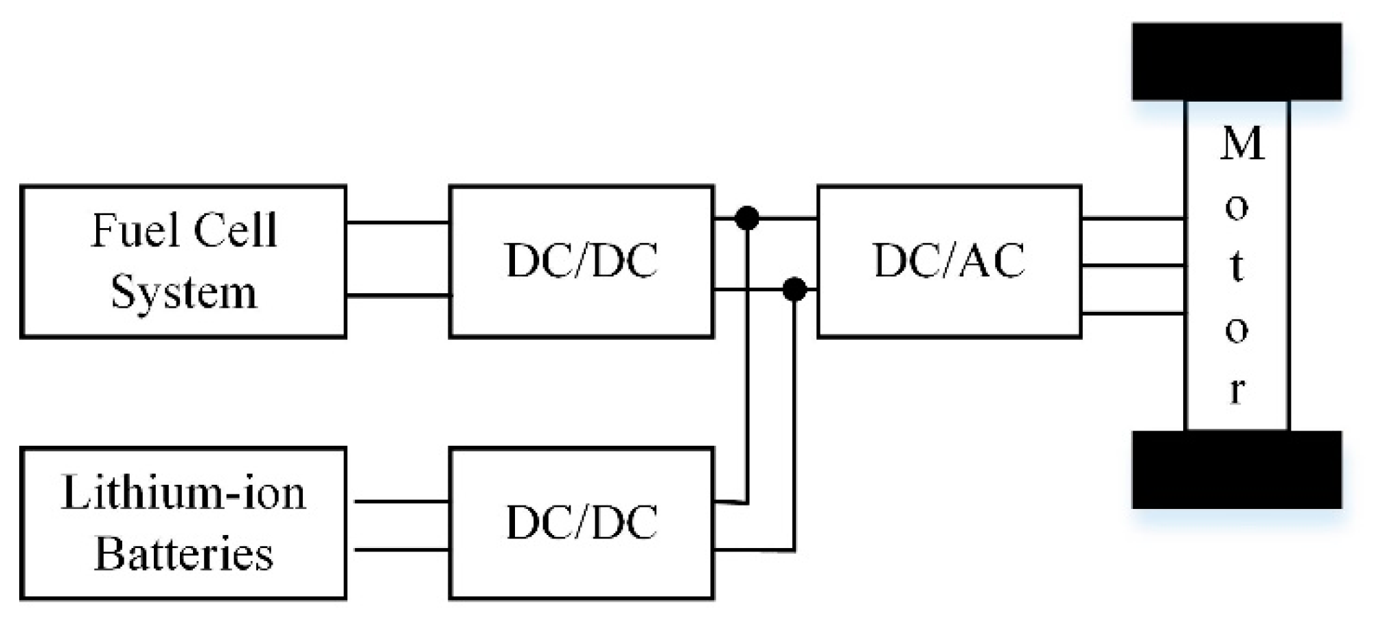
2.1. Power System Architecture

The hybrid power system mainly includes a fuel cell system, a lithium-ion battery pack, a DC/DC converter, etc., and its system architecture is shown in Figure 1. As the main energy source of the power system, the fuel cell outputs energy to the DC bus through a DC/DC converter. As an auxiliary energy source of the power system, lithium-ion batteries help fuel cells to suppress power fluctuations. Lithium-ion batteries can output energy to the DC bus, and can also store brake recovery energy and excess energy generated by fuel cells. The DC/AC converter completes the conversion of direct current and alternating current.
The power system architecture in this paper improves the fuel cell output characteristics and enhances the dynamic response capability of the power system. The structure of the hybrid power architecture is complex and requires a complete control strategy to control.

2.2. Fuel Cell Model

The equivalent circuit model of the fuel cell is shown in Figure 2. The behavior of the fuel cell exhibits a high degree of nonlinearity, and its output voltage has three losses: Activation losses due to reaction kinetics, Ohmic losses from ionic and electronic resistance, and mass transport causes concentration losses [22]:
V c e l l = E N e r n s t + η a c t + η o h m i c + η c o n c
where V c e l l represents the fuel cell voltage, E N e r n s t represents the Nernst voltage of the fuel cell, η a c t represents the activation voltage loss, η o h m i c represents the Ohmic voltage loss, and η c o n c represents the concentration voltage loss.
Proton exchange membrane fuel cells have an electric double layer phenomenon. The hydrogen ions that pass through the interface are separated from the electrons. Since the electrons gather on the surface of the electrode and the hydrogen ions gather on the surface of the electrolyte, the voltage generated between them can work like a capacitor [23]. This electrochemical reaction can be represented by the equivalent circuit model shown in Figure 2. The voltage loss corresponding to the activation loss and the quality loss can be calculated together.
The dynamic characteristic differential equation is expressed as:
d U C d l d t = I f c C d l U C d l ( R c o n c + R a c t ) C d l
where C d l represents the polarization capacitance, and U C d l represents the total polarization overvoltage.

2.3. Lithium-Ion Battery Model

The equivalent circuit model is selected in this paper in Figure 3. Furthermore, the model is selected for its good dynamic characteristics, and accuracy and complexity are all satisfied.
The electrical behavior of the cell model can be described as follows:
v = O C V R 1 I R 1 R 2 I R 2 R 0 I b a t
d I R 1 ( t ) d t = 1 R 1 C 1 I R 1 ( t ) 1 R 1 C 1 I b a t ( t )
d I R 2 ( t ) d t = 1 R 2 C 2 I R 2 ( t ) 1 R 2 C 2 I b a t ( t )
where v represents the cell terminal voltage, O C V represents the cell open-circuit voltage, R 1 and R 2 represent the polarization resistance, C 1 and C 2 represent the polarization capacitance of cell, R 0 represents the Ohmic internal resistance of cell, I R 1 and I R 2 represent the RC branch current, and I b a t represents the loop current.
Experimental data can be obtained through the lithium ion battery charge and discharge test device shown in Figure 4. The OCV-SOC curve can be obtained through the OCV-SOC calibration experiment. The voltage response of the lithium-ion battery to the current change is obtained through the pulse charge/discharge, and the parameter identification through the least square method can obtain the relationship between the model parameters and the SOC in the second-order RC equivalent circuit.

3. Analysis of Characteristics of Hybrid Power Source

3.1. Fuel Cell Characteristics Analysis

The fuel cell is a complex dynamic system with multi-input, nonlinear and time-varying characteristics. The operating conditions are key influence factors for the life of the fuel cell system [24]. The constraints can ensure the fuel cell to work under the right conditions, and its service life can be extended. In this section, we research the characteristics of the fuel cell (include steady-state characteristics and characteristics under dynamic conditions), and analyze the characteristics and corresponding mechanisms of fuel cell degradation and damage under different working conditions [25,26,27], and get the relevant constraints.
Fuel cell operation at the head of the polarization curve corresponding to the current density will lead to degradation of the catalytic layer. At the same time, its operation at the end of the polarization curve corresponding to the current density will cause the electrode surface current density distribution to be uneven. Constraints can be obtained from the polarization curve of the fuel cell:
i f c , p o l , min i f c i f c , p o l , max
where i f c represents fuel cell current density, and i f c , p o l , min and i f c , p o l , max represent current density limits considering the influence of polarization curve.
To the right of the maximum power point, the power density shows a downward trend, and its operating efficiency decreases. In actual operation, the fuel cell should avoid working in this area. Obtain constraints through the fuel cell power density curve:
i f c i f c , p w r , max
where i f c , p w r , max represents the current density limit considering the influence of maximum power density.
The voltage and current of a fuel cell have a coupling relationship. When the current changes, its voltage will change accordingly. Through the fuel cell Nernst equation, using Taylor’s formula expansion can obtain current density constraint:
i f c i f c , v o l , max
where i f c , v o l , max represent the current density limit considering the influence of terminal voltage.
It can be seen from the efficiency curve that the efficiency of the fuel cell system is very low when the power of the fuel cell system is small, so when the fuel cell is working normally, it needs to operate in the most efficient area of the fuel cell system. Obtain the constraints through the fuel cell efficiency curve:
i f c , e f f i c i e n c y , min i f c i f c , e f f i c i e n c y , max
where i f c , e f f i c i e n c y , min and i f c , e f f i c i e n c y , max represent the current density limits considering the influence of efficiency of the fuel cell system.
The current density of the fuel cell must meet various constraints:
{ i f c , max = min ( i f c , p o l , max , i f c , p w r , max ,   i f c , v o l , max , i f c , e f f i c i e n c y , max ) i f c , min = max ( i f c , p o l , min , i f c , e f f i c i e n c y , min )
The fuel cell voltage must also be within a certain range. If the voltage exceeds the voltage limit, the fuel cell will be damaged. Fuel cell voltage must also be within a certain range:
V f c , min V f c V f c , max
where V f c represents the fuel cell voltage, and V f c , min and V f c , max represent the voltage limits of the fuel cell.
Automobile load cycle is composed of start, idle speed, load change, high power demand, and stop cycle. Among them, start and stop and load change are the most important reasons for the aging of PEMFC [28,29,30]. Therefore, the number of start and stop times and status and load power changes can become effective indicators for evaluating the durability of PEMFC. In this paper, the role of lithium-ion battery is fully utilized, PEMFC is set to continue to turn on, and the lithium-ion battery is used to absorb excess energy to avoid life loss caused by startup and shutdown. Therefore, the load power change has become the main indicator for evaluating the deterioration of fuel cell life. During the vehicle operating conditions, changes in the motor load will affect the temperature and humidity of the proton membrane and the partial pressure of hydrogen and oxygen inside the fuel cell. Because of these factors, the fuel cell proton membrane will be physically damaged. It is necessary to set the fuel cell power fluctuation limit:
P f c _ lim i t P f c P f c _ lim i t
where P f c represents power change rate of the fuel cell, and P f c _ lim i t represents the power change rate limit.
Based on the previous analysis results, the start–stop of the fuel cell will cause life damage to the fuel cell. In order to avoid life damage caused by the start–stop of the fuel cell, the fuel cell is set to not stop during operation, and the excess energy can be stored in the lithium ion battery in. Therefore, the fuel cell needs to set the power output range:
P f c , min P f c P f c , max
where P f c , min represents minimum output power of the fuel cell, this value is set to the fuel cell idling power, P f c , max represents maximum output power of the fuel cell, and P f c represents output power of the fuel cell.

3.2. Lithium-Ion Battery Characteristics Analysis

As an auxiliary energy source, lithium-ion batteries have a significant impact on the performance of hybrid systems. The SOE (state of energy) is used to restrict the storage energy range of the lithium-ion battery [31], and the power capability is restricted by the SOP (state of power), so that the working performance and life of the lithium-ion battery are guaranteed.
The SOE of the battery cell is defined as follows:
S O E ( t ) = S O E ( t 0 ) + η t 0 t U b a t ( τ ) I ( τ ) d τ E
where E represents rated energy of the battery, and η represents energy efficiency:
S O E min S O E S O E max
where S O E min and S O E max represent limits of SOE.
SOP is an important indicator to predict the battery’s charge and discharge capabilities:
S O P = { P b , min c h g = max ( P b , min , V p a c k I b , min c h g ) P b , max d c h g = min ( P b , max , V p a c k I b , max d c h g )
where P b , min c h g and P b , max d c h g represent the minimum power capability for charging and maximum power capability for discharging (define negative for charging and positive for discharging), and P b , min and P b , max represent the cut-off power for charging and discharging. I b , min c h g and I b , max d c h g represent the minimum charging current and maximum discharging current that are affected by the designed current limits, the terminal voltage, and SOE:
{ I b , min c h g = max ( I b , min c h g , d e s , I b , min c h g , v o l t , I b , min c h g , S O E ) I b , max d c h g = min ( I b , max d c h g , d e s , I b , max d c h g , v o l t , I b , max d c h g , S O E )
where I b , min c h g , d e s and I b , max d c h g , d e s represent the designed current limits, I b , min c h g , v o l t and I b , max d c h g , v o l t represent the current considering the influence of terminal voltage, and I b , min c h g , S O E and I b , max d c h g , S O E represent the current considering the influence of SOE.
The calculation method of the above current is as follows:
{ I b , min c h g , v o l t = V o c v , k + L U 1 , k e L Δ t R 1 C 1 U 2 , k e L Δ t R 2 C 2 V b , max R 0 + R 1 ( 1 e Δ t R 1 C 1 ) j = 0 L 1 ( e Δ t R 1 C 1 ) L 1 j + R 2 ( 1 e Δ t R 2 C 2 ) j = 0 L 1 ( e Δ t R 2 C 2 ) L 1 j I b , max d c h g , v o l t = V o c v , k + L U 1 , k e L Δ t R 1 C 1 U 2 , k e L Δ t R 2 C 2 V b , min R 0 + R 1 ( 1 e Δ t R 1 C 1 ) j = 0 L 1 ( e Δ t R 1 C 1 ) L 1 j + R 2 ( 1 e Δ t R 2 C 2 ) j = 0 L 1 ( e Δ t R 2 C 2 ) L 1 j
{ I b , min c h g , S O E = ( S O E k S O E max ) E η L Δ t V k I b , max d c h g , S O E = ( S O E k S O E min ) E η L Δ t V k
where L represents continuous charge and discharge time (the value is 5s in the paper), and Δ t represents the sampling time.

4. Mathematical Modeling of Optimization Problems

The essence of the power distribution control strategy is the optimization problem. Its goal is to find a distribution plan that meets the cost target in the work area. In many fields such as electric power and energy storage, nonlinear programming algorithms have been well applied [32]. In this paper, the optimization results of power distribution can be obtained through a nonlinear programming algorithm.

4.1. Objective Function
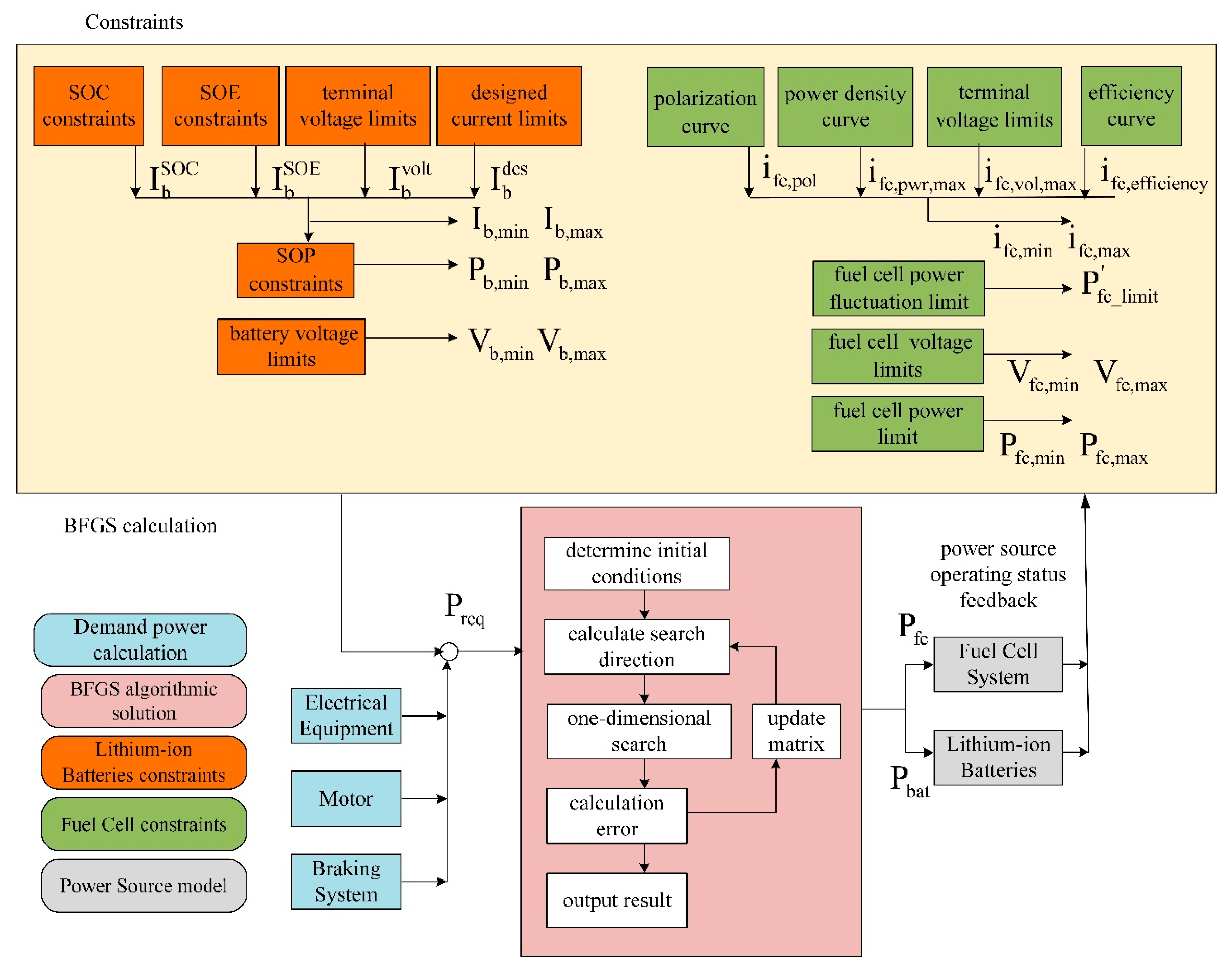
Fuel economy is an important characteristic of hybrid vehicles, and strategies aimed at minimizing fuel consumption are common [33,34]. When considering the fuel cost objective function, it is necessary to equivalently convert the electric energy consumption value of the battery pack:
min f ( x ) = M H 2 _ f c ( 1 + 0 T I b a t U b a t d t 0 T I s t a c k U s t a c k d t )
where I b a t and U b a t represent current and voltage of the lithium-ion battery, I s t a c k and U s t a c k represent current and voltage of fuel cell, and r M H 2 _ f c represents hydrogen consumption of the fuel cell.
The hydrogen consumption of fuel cell can be calculated as:
M H 2 _ f c = 0 T 2.02 × 10 3 P 2 F V d d t
where P represents the power fuel cell, F represents Faraday constant, and V d represents the single fuel cell voltage.

4.2. Constraints

Establish the behavior boundary of the power source based on the analysis of the characteristics of different power sources. In addition, the hybrid power system must meet the power requirements of the vehicle, and the hybrid power system must be able to supply the power required by the motor:
P f c η D C / D C , f c + P b a t η D C / D C , b a t = P r e q
where P r e q represents the required power of the motor; η D C / D C , f c represents the efficiency of the DC/DC converter connected to the fuel cell; and η D C / D C , b a t represents the efficiency of the DC/DC converter connected to the lithium ion battery.
All constraints of the nonlinear programming algorithm are as follows:
s . t . P f c η D C / D C , f c + P b a t η D C / D C , b a t = P r e q S O E min S O E S O E max I b , min c h g I b a t I b , max d c h g V b , min V b a t V b , max P b , min c h g P b a t P b , max d c h g i f c , min i f c i f c , max V f c , min V f c V f c , max P f c , min P f c P f c , max P f c _ lim i t P f c P f c _ lim i t
where s . t . represents subject to, and constraints are based on the above analysis of the characteristics of fuel cells and lithium-ion batteries. The formulation of these constraints can ensure that the power source operates well.

4.3. Nonlinear Programming Algorithm Calculation Process

The mathematical model of nonlinear programming is:
min f ( X ) s . t . { g i ( X ) 0 , i = 0 , 1 , 2 , m h j ( X ) = 0 , j = 1 , 2 , , l
where s . t . represents subject to, X represents the vector or point in n-dimensional Euclidean space; f ( X ) , g i ( X ) , and h j ( X ) represent the function defined in the space [35].
The quasi-Newton method is a classic method in nonlinear programming algorithms, suitable for dealing with engineering problems. The BFGS algorithm (Broy-den, C.G., Fletcher, R., Goldforb, D., Shanno, D.F. algorithm) [36] is a kind of nonlinear programming algorithm, which is used in this paper. The paper uses the fminunc function in MATLAB, which can choose to use the BFGS algorithm to solve nonlinear problems. The BFGS method is the most effective algorithm in the quasi-Newton method because the calculation amount of each iteration is small while maintaining super linear convergence. Refs. [37,38] elaborate on the convergence proof of the algorithm. The BFGS method replaces H 1 with a matrix B 1 without the second derivative, and its quasi-Newton condition is:
Δ x t = B t + 1 1 Δ g t
where Δ x t represents the distance of the iteration point, and Δ g t represents the gradient difference of the iteration point.
The specific steps of BFGS method calculation are:
  • Determine the initial point x ( 0 ) , allowable error ε , and the initial value of the approximate matrix B 0 1 .
  • Determine the search direction d ( t ) = B t 1 g t .
  • Do a one-dimensional search along d ( t ) from the current point x ( t ) to obtain the optimal step length λ t and update the current point x ( t + 1 ) = x ( t ) + λ t d ( t ) .
  • If | g t + 1 | < ε , stop the iteration; otherwise, go to step 5.
  • Calculate Δ g = g t + 1 g t , Δ x = x ( t + 1 ) x ( t ) update the approximate matrix B t + 1 1 . t = t + 1 , and go to step 2.
The BFGS algorithm calculation flowchart is shown in Figure 5. The power distribution strategy calculation process is shown in Figure 6.
After obtaining the required power of the motor, the hybrid power distribution control strategy performs power distribution in four steps:
  • Get the demand for motor power and input to the power distribution module with the operating parameter of the power source.
  • Determine the value of constraints. Some constraints are fixed, and some constraints change in real time with the state of the power sources. Real-time calculations are required for the value of constraints that change in real time. After the calculation, the feasible field of the operation point is determined.
  • The nonlinear programming algorithm solves the optimization problem based on initial conditions and variable thresholds. The algorithm takes the initial point as a starting point and performs a one-dimensional search along the search direction. When the gradient difference is satisfied, the iteration is stopped and the power distribution is over.
  • Fuel cell and lithium-ion battery output power based on the allocated result and feedback operating status. (Considering the calculation complexity and accuracy, this paper assumes that the optimization result is constant within the unit interval of the power distribution control strategy.)
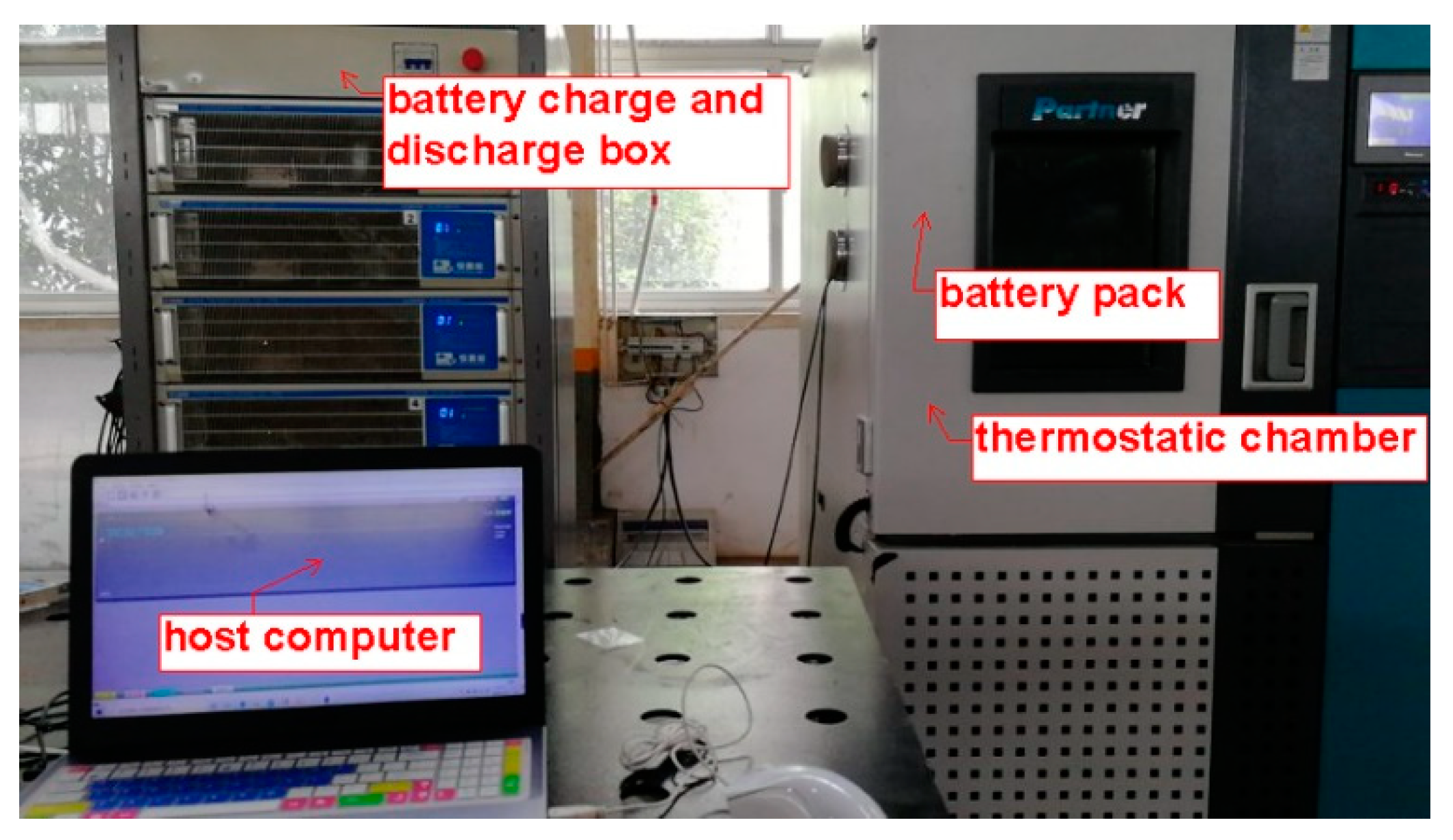
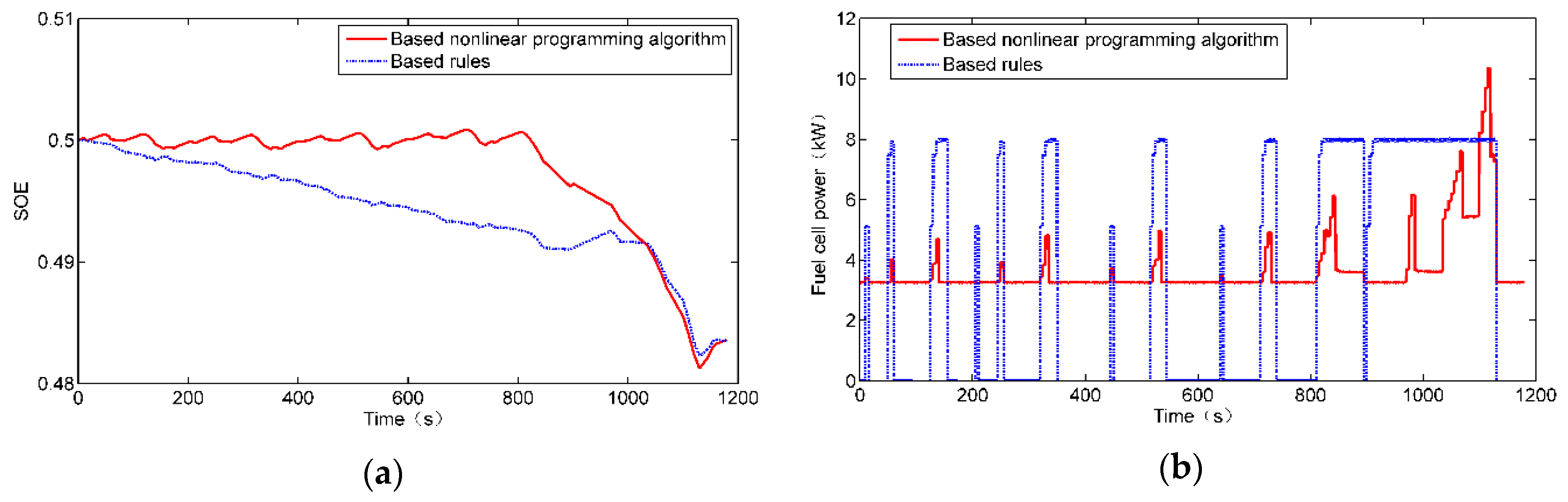
5. Simulation Study

This article uses NEDC (New European Driving Cycle) and UDDS (Urban Dynamometer Driving Schedule) as test conditions. NEDC is a synthetic driving condition formulated in accordance with European operating conditions. The first half is a traditional urban road driving condition, and the second half is an additional suburban driving condition. UDDS is a synthetic driving condition formulated in accordance with American operating conditions. This article uses a rule-based power distribution strategy for comparison. The dynamic indicators and related parameters used in this paper are shown in Table 1. This paper uses a rule-based power following power allocation strategy for comparison [39].
It can be seen from Figure 7 that the hybrid power system can meet the required power regardless of the NEDC operating condition or the UDDS operating condition. In the urban operating conditions in Figure 7a, four cycles of acceleration and deceleration were performed. Taking the data of the first cycle as an example, the required power increases at 20 s, 55 s, and 125 s. When the required power is small, all the constraints are met. At 975 s, when conditions are not met, fuel cell power is limited because durability has priority over the economy.
It can be seen from Figure 8a that, in a working condition cycle, the nonlinear programming algorithm keeps the SOE near a fixed value under the urban working condition. When the vehicle load increases rapidly, the SOE drops faster; this is to avoid the rapid change of the fuel cell power and make the lithium-ion battery output high power. The lithium-ion battery needs to bear the high-power output, which brings buffer time for the fuel cell system to increase the power, so that the fuel cell system can slowly increase the power. The lithium-ion battery has the ability of high power output in a short time, and such high power output will not affect its life span at all.
It can be seen from Figure 8b that, when the output power increases rapidly, the power of the fuel cell rises slowly, which is the result of corresponding constraints. The disadvantage of the fuel cell system is not that it cannot output high power. Its disadvantage is that it cannot output high power in a short time like an internal combustion engine. Short-term power fluctuations will damage the life of the fuel cell. For example, a sudden increase in airflow will result in dehydration of the proton exchange membrane, and a sudden decrease in airflow will result in a large amount of water that cannot be discharged with the airflow.
It can be seen from Figure 9a that, in the NEDC working state cycle, under the control of the control strategy based on the optimized algorithm, the power fluctuation of the lithium ion battery is more severe. This proves that the lithium-ion battery is responsible for the power distribution. More. Correspondingly, the fuel cell system can obtain smaller power fluctuations. The lithium-ion battery is like a buffer zone, which can output power as much as possible when the power demand is large; when the power demand is small or negative (recover braking energy), the excess power is recovered.
It can be seen from Figure 9b that the voltage performance of the fuel cell is very soft, and the voltage fluctuation caused by the change of the load current is relatively large, so it can be seen that the voltage and power changes have a corresponding relationship. The fuel cell voltage is in the safe range under the operating conditions of the two control strategies. The control strategy based on the optimization algorithm makes the voltage of the fuel cell change slowly and continuously, which helps to ensure its life.
The two control strategies are evaluated for economy and durability. It can be seen from Table 2 that, under the two operating conditions, the control strategy using the optimization algorithm is not economically superior to the rule-based control strategy. Constraints set by considering the lifetime will limit the operating range of the hybrid energy storage system, which reduces the operating range of the optimization algorithm. The algorithm can only search for the best within the range that meets the life requirements, which may not have economic advantages in terms of results, but the economic optimization under the premise of life guarantee has been achieved. However, its power fluctuation can be well suppressed. The standard deviation of its power fluctuation is 71.5% and 58.8% based on the rule strategy. Due to the high cost of fuel cells, it is worthwhile to obtain a substantial extension of fuel cell life with little loss of hydrogen consumption.
In order to study the influence of the constraint SOP on the results, the simulation results of adding and removing SOP are compared with the existing results, as shown in Table 3. This paper finds that the power capability constraint SOP greatly improves durability and economy. The use of SOP constraints can reduce high power shocks and extend the life of the power source. The energy loss of the DC/DC converter is also reduced as well as the fuel economy of the system is improved. The use of SOP constraints can reduce high-power shocks and extend the life of the power source. The energy loss of the DC/DC converter is therefore reduced, and the fuel economy of the system is improved. When SOP is used as the power constraint of lithium-ion batteries, the equivalent hydrogen consumption in NEDC and UDDS has dropped significantly. It can be seen from Table 3 that the equivalent hydrogen consumption decreased by 12.3% after using SOP constraint compared with the case without SOP. At the same time, its power fluctuation is also suppressed.

6. Conclusions

In this paper, based on the research of fuel cell hybrid electric vehicles, a simulation model of the fuel cell hybrid system was established. Analysis of the characteristics of fuel cells expands the constraints of fuel cell durability. The BFGS algorithm is used in the formulation of power distribution control strategies. Simulation results show that the formulated power distribution control strategies have good adaptability under urban conditions. Compared with the rule-based control strategy, the power distribution control strategy, which is based on the BFGS algorithm in this paper, makes the power source show better durability and is suitable for engineering applications.

Author Contributions

Conceptualization, Y.H. and X.Z.; methodology, J.W.; software, X.L. (Xintian Liu); validation, X.L. (Xingtao Liu); formal analysis F.H.; investigation, C.M.; resources, X.Z.; data curation, J.W.; writing—original draft preparation, C.M.; writing—review and editing, Y.H.; visualization, F.H.; supervision, Y.H.; project administration, Y.H.; funding acquisition, Y.H. All authors have read and agreed to the published version of the manuscript.

Funding

This work is supported in part by the Nature Science Research Project of Anhui province(2008085UD04) and in part by the Fundamental Research Funds for the Central Universities under Grant(No. JZ2019HGBZ0119).

Institutional Review Board Statement

Not applicable.

Informed Consent Statement

Not applicable.

Data Availability Statement

Not applicable.

Conflicts of Interest

The authors declare no conflict of interest.

References

  1. Ryan, O.; Sukwon, C.; Whitney, C. Fuel cell fundamentals, 3rd edition. Mech. Eng. 2016, 9, 1–6. [Google Scholar]
  2. Xiong, R.; Li, L.; Tian, J. Towards a smarter battery management system: A critical review on battery state of health monitoring methods. J. Power Sources 2018, 405, 18–29. [Google Scholar] [CrossRef]
  3. Hannan, M.A.; Azidin, F.A.; Mohamed, A. Multi-sources model and control algorithm of an energy management system for light electric vehicles. Energy Convers. Manag. 2012, 62, 123–130. [Google Scholar] [CrossRef]
  4. Li, Q.; Chen, W.; Liu, Z.; Li, M.; Ma, L. Development of energy management system based on a power sharing strategy for a fuel cell-battery-supercapacitor hybrid tramway. J. Power Sources 2015, 279, 267–280. [Google Scholar] [CrossRef]
  5. Wang, Z.; Xie, Y.; Sun, W.; Zang, P. Modeling and Energy Management Strategy Research of Fuel Cell Bus. J. Tongji Univ. (Nat. Ence) 2019, 47, 97-103+123. [Google Scholar]
  6. Sockeel, N.; Shahverdi, M.; Mazzola, M.; Meadows, W. High-Fidelity Battery Model for Model Predictive Control Implemented into a Plug-In Hybrid Electric Vehicle. Batteries 2017, 3, 13. [Google Scholar] [CrossRef] [Green Version]
  7. Sockeel, N.; Shi, J.; Shahverdi, M.; Mazzola, M. Sensitivity Analysis of the Battery Model for Model Predictive Control: Implementable to a Plug-In Hybrid Electric Vehicle. World Electr. Veh. J. 2018, 9, 45. [Google Scholar] [CrossRef] [Green Version]
  8. Garcia, P.; Fernandez, L.M.; Garcia, C.A.; Jurado, F. Energy Management System of Fuel-Cell-Battery Hybrid Tramway. IEEE Trans. Ind. Electron. 2009, 57, 4013–4023. [Google Scholar] [CrossRef]
  9. Li, Q.; Chen, W.; Wang, Y.; Jia, J.; Han, M. Nonlinear robust control of proton exchange membrane fuel cell by state feedback exact linearization. J. Power Sources 2009, 194, 338–348. [Google Scholar] [CrossRef]
  10. Florescu, A.; Bacha, S.; Munteanu, I.; Bratcu, A.I. Frequency-Separation-Based Energy Management Control Strategy of Power Flows within Electric Vehicles using Ultracapacitors. In Proceedings of the Conference of the IEEE Industrial Electronics Society IEEE, Montreal, QC, Canada, 25–28 October 2012. [Google Scholar]
  11. Wang, Y.; Sun, Z.; Chen, Z. Development of energy management system based on a rule-based power distribution strategy for hybrid power sources. Energy 2019, 175, 1055–1066. [Google Scholar] [CrossRef]
  12. Zhang, H.; Li, X.; Liu, X.; Yan, J. Enhancing fuel cell durability for fuel cell plug-in hybrid electric vehicles through strategic power management. Appl. Energy 2019, 241, 483–490. [Google Scholar] [CrossRef]
  13. Xiong, R.; Duan, Y.; Cao, J.; Yu, Q. Battery and ultracapacitor in-the-loop approach to validate a real-time power management method for an all-climate electric vehicle. Appl. Energy 2018, 217, 153–165. [Google Scholar] [CrossRef]
  14. Hong, Z.; Li, Q.; Han, Y.; Shang, W.; Zhu, Y.; Chen, W. An energy management strategy based on dynamic power factor for fuel cell/battery hybrid locomotive. Int. J. Hydrog. Energy 2018, 43, 3261–3272. [Google Scholar] [CrossRef]
  15. Tribioli, L.; Cozzolino, R.; Chiappini, D.; Iora, P. Energy management of a plug-in fuel cell/battery hybrid vehicle with on-board fuel processing. Appl. Energy 2016, 184, 140–154. [Google Scholar] [CrossRef]
  16. Bizon, N. Real-time optimization strategies of Fuel Cell Hybrid Power Systems based on Load-following control: A new strategy, and a comparative study of topologies and fuel economy obtained. Appl. Energy 2019, 241, 444–460. [Google Scholar] [CrossRef]
  17. Hu, Z.; Li, J.; Xu, L.; Song, Z.; Fang, C.; Ouyang, M.; Dou, G.; Kou, G. Multi-objective energy management optimization and parameter sizing for proton exchange membrane hybrid fuel cell vehicles. Energy Convers. Manag. 2016, 129, 108–121. [Google Scholar] [CrossRef]
  18. Torreglosa, J.; Jurado, F.; García, P.; Fernández, L. Hybrid fuel cell and battery tramway control based on an equivalent consumption minimization strategy. Control Eng. Pract. 2011, 19, 1182–1194. [Google Scholar] [CrossRef]
  19. Kermani, S.; Delprat, S.; Guerra, T.M.; Trigui, R. Predictive Control for HEV Energy Management: Experimental Results. In Proceedings of the IEEE Vehicle Power and Propulsion Conference (VPPC), Dearborn, MI, USA, 7–11 September 2009. [Google Scholar]
  20. Yu, K.; Xu, X.; Liang, Q.; Hu, Z.; Yang, J.; Guo, Y.; Zhang, H. Model Predictive Control for Connected Hybrid Electric Vehicle. Math. Probl. Eng. 2015, 2015. [Google Scholar] [CrossRef] [Green Version]
  21. Xu, L.; Ouyang, M.; Li, J.; Yang, F.; Lu, L.; Hua, J. Application of Pontryagin’s Minimal Principle to the energy management strategy of plugin fuel cell electric vehicles. Int. J. Hydrog. Energy 2013, 38, 10104–10115. [Google Scholar] [CrossRef]
  22. Khan, M.J.; Iqbal, M.T. Modelling and Analysis of Electro-chemical, Thermal, and Reactant Flow Dynamics for a PEM Fuel Cell System. Fuel Cells 2005, 5, 463–475. [Google Scholar] [CrossRef]
  23. Chen, H.; Pei, P. Dynamic model of a proton exchange membrane (PEM) fuel cell during load changes. J. Tsinghua Univ. 2014, 54, 1298–1303. [Google Scholar]
  24. Pei, P.; Chen, H. Main factors affecting the lifetime of Proton Exchange Membrane fuel cells in vehicle applications: A review. Appl. Energy 2014, 125, 60–75. [Google Scholar] [CrossRef]
  25. Rong, F.; Huang, C.; Liu, Z.S.; Song, D.; Wang, Q. Microstructure changes in the catalyst layers of PEM fuel cells induced by load cycling: Part II. Simulation and understanding. J. Power Sources 2008, 175, 712–723. [Google Scholar] [CrossRef]
  26. Shen, Q.; Hou, M.; Liang, D.; Zhou, Z.; Li, X.; Shao, Z.; Yi, B. Study on the processes of start-up and shutdown in proton exchange membrane fuel cells. J. Power Sources 2009, 189, 1114–1119. [Google Scholar] [CrossRef]
  27. Pei, P.; Chang, Q.; Tang, T. A quick evaluating method for automotive fuel cell lifetime. Int. J. Hydrog. Energy 2008, 33, 3829–3836. [Google Scholar] [CrossRef]
  28. Kocha, S.S. Electrochemical degradation: Electrocatalyst and support durability. In Polymer Electrolyte Fuel Cell Degradation; Academic Press: Oxford, UK, 2012; pp. a89–214. [Google Scholar]
  29. Ousfi-Steiner, N.Y.; Moc ¸otéguy, P.; Candusso, D.; Hissel, D. A review on polymer electrolyte membrane fuel cell catalyst degradation and starvation issues: Causes, consequences and diagnostic for mitigation. J. Power Sources 2009, 194, 130–145. [Google Scholar] [CrossRef]
  30. Zhang, X.; Yang, D.; Luo, M.; Dong, Z. Load profile based empirical model for the lifetime prediction of an automotive PEM fuel cell. Int. J. Hydrog. Energy 2017, 42, 11868–11878. [Google Scholar] [CrossRef]
  31. Zhang, Y.; Xiong, R.; He, H.; Shen, W. Lithium-Ion Battery Pack State of Charge and State of Energy Estimation Algorithms Using a Hardware-in-the-Loop Validation. IEEE Trans. Power Electron. 2017, 32, 4421–4431. [Google Scholar] [CrossRef]
  32. Xiong, R.; He, H.; Sun, F.; Liu, X.; Liu, Z. Model-based state of charge and peak power capability joint estimation of lithium-ion battery in plug-in hybrid electric vehicles. J. Power Sources 2013, 229, 159–169. [Google Scholar] [CrossRef]
  33. Xiong, R.; He, H.; Sun, F.; Zhao, K. Online Estimation of Peak Power Capability of Li-Ion Batteries in Electric Vehicles by a Hardware-in-Loop Approach. Energies 2012, 5, 1455–1469. [Google Scholar] [CrossRef]
  34. Wu, J.; Xing, X.; Liu, X.; Guerrero, J.M.; Chen, Z. Energy Management Strategy for Grid-Tied Microgrids Considering the Energy Storage Efficiency. IEEE Trans. Ind. Electron. 2018, 65, 9539–9549. [Google Scholar] [CrossRef] [Green Version]
  35. Nocedal, J.; Wright, S.J. Numerical Optimization, 2nd ed.; Springer: New York, NY, USA, 2006. [Google Scholar]
  36. Schraudolph, N.N.; Yu, J.; Günter, S. A Stochastic Quasi-Newton Method for Online Convex Optimization. J. Mach. Learn. Res. 2007, 2, 436–443. [Google Scholar]
  37. Grant, M.; Boyd, S.; Ye, Y. Disciplined Convex Programming. Nonconvex Optim. Its Appl. 2007, 84, 155–210. [Google Scholar]
  38. Grant, M.C.; Boyd, S.P. Graph Implementations for Nonsmooth Convex Programs. Lect. Notes Control Inf. Sci. 2008, 371, 95–110. [Google Scholar]
  39. Xing, X.; Su, Z.; Tinghong, W.; Fengxiang, C. A simulation on energy management strategy for the power system of a fuel cell/battery HEV based on Cruise/Simulink. Automot. Eng. 2010, 32, 373–378. [Google Scholar]
Figure 1. Powertrain system structure of the fuel cell vehicle.
Energies 14 00734 g001
Figure 2. Equivalent circuit model of PEMFC.
Energies 14 00734 g002
Figure 3. Equivalent circuit model of the lithium-ion battery.
Energies 14 00734 g003
Figure 4. Lithium ion battery charge and discharge test device.
Energies 14 00734 g004
Figure 5. BFGS algorithm calculation flowchart.
Energies 14 00734 g005
Figure 6. Power distribution computational model.
Energies 14 00734 g006
Figure 7. (a) The simulation of nonlinear programming in the NEDC condition; (b) the simulation of nonlinear programming in the UDDS condition.
Energies 14 00734 g007
Figure 8. (a) Battery SOE curves in NEDC condition; (b) fuel cell output power curves in the NEDC condition.
Energies 14 00734 g008
Figure 9. (a) Battery output power curves in the NEDC condition; (b) fuel cell output voltage curves in the NEDC condition.
Energies 14 00734 g009
Table 1. Type of reference parameters of the powertrain system.
ParameterValueParameterValue
Vehicle quality/kg1400Fuel cell rated power/kW30
Motor rated power/kW30Battery rated power/kW60
Motor peak power/kW60battery capacity/Ah30
Table 2. Simulation comparison between the nonlinear programming strategy and power following strategy.
Vehicle ConditionControl StrategyEquivalent Hydrogen Consumption (kg)Power Fluctuation (kW)
UDDSAlgorithm0.1151.084
UDDSRule0.0993.799
NEDCAlgorithm0.1071.524
NEDCRule0.1023.696
Table 3. Simulation comparison of SOP.
Vehicle ConditionSOPEquivalent Hydrogen Consumption (kg)Power Fluctuation (kW)
NEDCWithout SOP0.1221.585
NEDCWith SOP0.1071.524
UDDSWithout SOP0.1311.147
UDDSWith SOP0.1151.084
Publisher’s Note: MDPI stays neutral with regard to jurisdictional claims in published maps and institutional affiliations.

