Article

Evaluation of Formate Salt PCM’s for Latent Heat Thermal Energy Storage

1
National Renewable Energy Laboratory, 15013 Denver West Parkway, Golden, CO 80401, USA
2
Los Alamos National Laboratory, M711, Los Alamos, NM 87545, USA
*
Author to whom correspondence should be addressed.
Energies 2021, 14(3), 765; https://doi.org/10.3390/en14030765
Submission received: 10 December 2020 / Revised: 15 January 2021 / Accepted: 27 January 2021 / Published: 1 February 2021
(This article belongs to the Special Issue Phase Change Materials for Thermal Energy Storage Applications)

Abstract

:
This work examines formate salts as potential phase change materials (PCMs) for middle-high temperature (≤250 °C) latent heat thermal energy storage applications. The thermophysical properties of three formate salts were characterized: pure sodium formate and binary blends of sodium/potassium formate and sodium/calcium formate. The stability of formate PCM’s was evaluated by thermal cycling using differential scanning calorimetry where sodium formate and sodium/potassium formate appeared stable over 600 cycles, while sodium/calcium formate exhibited a monotonic decrease in heat of fusion over the test period. A longer test with sodium formate led to gas release and decomposition of the salt. FTIR analysis of the PCM showed degradation of formate to oxalate. T-history experiments with 50-g PCM quantities demonstrated a bulk supercooling of only 2–3 °C for these salts. Thermal conductivity enhancement of over 700% was achieved by embedding aluminum in the solid PCM. Finally, mild carbon steel was immersed in molten sodium formate for up to 2000 h. Sodium formate was found to be non-corrosive, as calculated by mass loss and confirmed by cross-sectional high-resolution microscopy. FTIR analysis of the PCM after 2000 h shows oxidation at the free surface, while the bulk PCM remained unchanged, further indicating a need to protect the formate from atmospheric exposure when used as a PCM.

1. Introduction

Industry is a major source of global carbon emissions and accounts for nearly 30% of the world’s annual energy consumption. Fossil fuel demand is often driven by the need for industrial process heat. A recent study found that while 90% of industrial process heat is currently provided by fossil fuels, over 50% of heat demand is for temperatures of 300 °C or below [1]. Solar thermal technology offers industry a more sustainable alternative thermal source, which may significantly reduce carbon emissions. Solar thermal energy is often associated with electricity generation using high temperature concentrating solar power (CSP). However, solar thermal energy for industrial process heat can be a much simpler and cheaper process compared to electricity production, as the heat can be efficiently utilized without heat-to-electricity conversion losses associated with electricity generation [2].
Solar thermal systems frequently seek to include thermal energy storage (TES) in order to provide greater operating flexibility. Thermal energy can be stored using sensible, latent, or thermochemical energy means. Latent heat storage stores heat at constant temperature by changing its phase, in addition to storing heat in the form of sensible heat. Phase change materials (PCMs) have significantly higher energy density and are typically smaller size compared to sensible heat storage [3]. Latent-heat TES is particularly relevant for steam generation systems, where the PCM melting point and steam supply temperature can ideally be aligned for efficient energy transfer [4]. Furthermore, modest pressure steam use is common throughout industry, making this application a good target for solar thermal energy. Steam supply at less than 260 °C, accounts for much of the steam demand across multiple manufacturing sectors in the United States [5]. However, finding suitable PCMs in this temperature range remains challenging. Waxes have been a well-studied PCM system, but these have melting points lower than the temperature demands for process heat steam [6]. Suitable molten salt PCMs are often limited to expensive lithium-bearing eutectics or suffer from low latent heat of fusion (e.g., sodium nitrate, ΔHfusion = 199 J/g·K) [7].
Finding an appropriate PCM requires matching the PCM melting point to the desired steam-supply range, with the desired melting point being slightly higher than the target steam supply saturation temperature. In addition to an appropriate melting point, an ideal PCM should have a large heat of fusion, good thermal conductivity, a sharp phase transition (minimal supercooling or superheating required), low toxicity, chemical stability, and low cost.
One of the major challenges of most low-cost PCMs is their relatively low thermal conductivity (between 0.2 and 0.7 W/m·K), which limits power into and out of the PCM [6]. Methods have been proposed in the literature for enhancing the thermal conductivity of PCMs, including introducing additive enhancers to the matrix, e.g., steel wool, carbon fiber, aluminum, copper, or graphite [6,8,9].
Long term stability of PCMs is also a critical point. Although a given PCM candidate may exhibit a desirable melting point and latent heat, commercial-scale thermal storage requires reliable thermal behavior after repeated thermal cycling. The PCM must exhibit no significant changes in the melting temperature or the latent heat, in order to be economically feasible for use in latent heat storage [10], and have a consistent performance over its life. The PCM and the storage container must also be chemically compatible. Success of commercial PCM storage is dependent on whether common, low-cost alloys are corrosion resistant to the PCM [11].
This work investigates a relatively unexplored class of PCMs based on formate salts. A previous study identified formate salts as potential candidates to meet the techno-economic requirements for latent heat TES [4]. Sodium formate is a commodity chemical with low hazard and health concerns, often used as a deicing agent. It is nonflammable, nonexplosive, and reportedly stable to at least 330 °C (decomposition reported at 400 °C) [12]. This temperature range suggests that sodium formate could be a viable thermal storage medium for industrial process heat and steam. With a reported low cost of $0.40/kg, this salt can be a viable economic option for latent heat TES [4]. Despite their apparent benefits, the thermochemical properties of formate salts as PCMs have not been thoroughly characterized. In this study, the thermal stability of sodium formate, sodium/potassium formate eutectic, and sodium/calcium formate eutectic are assessed by thermal cycling the PCM using differential scanning calorimetry (DSC). Bulk PCM supercooling is quantified using T-history experiments, and the corrosivity of molten formate salts is characterized over long duration exposure times up to 2000 h. The thermal conductivity of formate salt PCM is characterized with and without additive thermal conductivity enhancers (aluminum rings). These efforts evaluate the thermochemical properties of formate salts to assess their viability as low-cost, middle-high temperature PCMs for latent heat thermal energy storage.

2. Materials and Methods

The thermal and chemical properties of formate salt PCMs were investigated using multiple analytical characterization techniques, which assessed latent heat, thermal stability, thermal conductivity, supercooling, and corrosiveness. These properties were documented for sodium formate and eutectics of sodium/potassium formate and sodium/calcium formate. Sodium formate and potassium formate were sourced from Alpha Aesar (99.0% min.). Calcium formate was sourced from Sigma Aldrich (≥99.0%). Eutectic blends were prepared by mixing dry powders by hand at the proper ratios (44.2:55.8 wt.%, sodium formate: potassium formate and 68.4:31.6 wt.%, sodium formate: calcium formate). The powders were fully melted and cooled under nitrogen, crushed into powder, and stored under inert atmosphere due to their hygroscopic nature.

2.1. Latent Heat and Thermal Stability of PCMs

The stability of the PCMs was evaluated by performing thermal cycling and measuring the degradation of the latent heat of fusion (Hf) over the cycling duration inside a TA Q500 DSC. PCM samples ranging in mass between 10–20 mg were repeatedly cycled to measure stability over multiple melting and freezing events (up to 1500 cycles). PCMs were dried in a vacuum oven at 110 °C overnight to remove physisorbed water from the sample. The PCMs were then transferred quickly to an inert glovebox, where 10–20 mg of sample was hermetically sealed in aluminum pans with solid (no pinhole) lids. Latent heat and thermal stability experiments were conducted with a 20 °C/min ramp rate. The PCMs thermal cycle ranges were between 160 and 280 °C (sodium formate), 160 and 275 °C (sodium/calcium formate), and 100 and 200 °C (sodium/potassium formate). Degradation in PCMs was measured using a Nicolet 5700 Fourier transform infrared spectrometer (FTIR), equipped with a diamond attenuated total reflection (ATR) accessory.

2.2. Thermal Conductivity/Thermal Enhancement

Aluminum rings (~5 mm diameter and length × 0.01 mm thick) were manufactured out of Al 6061 sheet and deployed into the PCM to enhance thermal conductivity. Rings were placed inside a beaker containing approximately 50 g of PCM. The rings were oriented such that the rings spanned the entire depth of the PCM. Once the PCM was completely melted, the beaker of PCM was then simultaneously shaken and actively cooled from the bottom to remove air bubbles from the solidifying PCM. The circular solid wafer of PCM (nominally 50 mm in diameter and 8 mm thick) was then measured with and without aluminum rings using a TA DTC 300 steady-state guarded heat flow meter according to the ASTM E1530 standard. Per sample the effective volume fraction of the aluminum rings was approximately 5% to the approximately 95% volume of PCM.

2.3. T-History Method

Yinping et al. introduced the concept of T-history for measuring the latent heat, specific heat, and thermal conductivity of PCMs [13]. The proposed concept can also be used for measuring degree of supercooling. The T-history setup used glycerol as reference material. The mass of PCM used was 50 g. PCM and glycerol reference were placed in separate stainless-steel beakers. Stainless-steel beakers were chosen because of their chemical compatibility with molten formate salts and to reduce risk of vessel breakage by multiple freeze thaw events. The furnace temperature was adjusted to correlate with the PCM melting point. The PCM and the glycerol temperatures were gradually increased. Once the PCM was melted, the furnace was shut down. The PCM and the glycerol were gradually allowed to cool, and the cycle was repeated. Eight thermocouples were used in the PCM to increase accuracy of temperature measurement. The temperature vs. time plot for the PCM and the glycerol was then plotted to calculate the degree of supercooling.

2.4. Corrosion Studies

The corrosion of mild carbon steel in molten sodium formate was evaluated for up to 2000 h. Rectangular coupons of dimensions 1.0″ × 0.5″ × 0.06″ were machined using water jet cutting. A 13/64” (5.16 mm) diameter hole was drilled to support the immersed coupon. Multiple coupons of each alloy were hung of nickel wire hangers and suspended a glass beaker with 150 g of molten sodium formate (temperature 280 °C). Experiments were conducted inside a furnace which was constantly purged with nitrogen at 100 mL/min. However, the furnace was not fully sealed from atmosphere. The corrosion of the coupons was assessed in 500-h increments by calculating mass loss and confirmed by high resolution microscopy of cross-sectioned coupons.

3. Results and Discussion

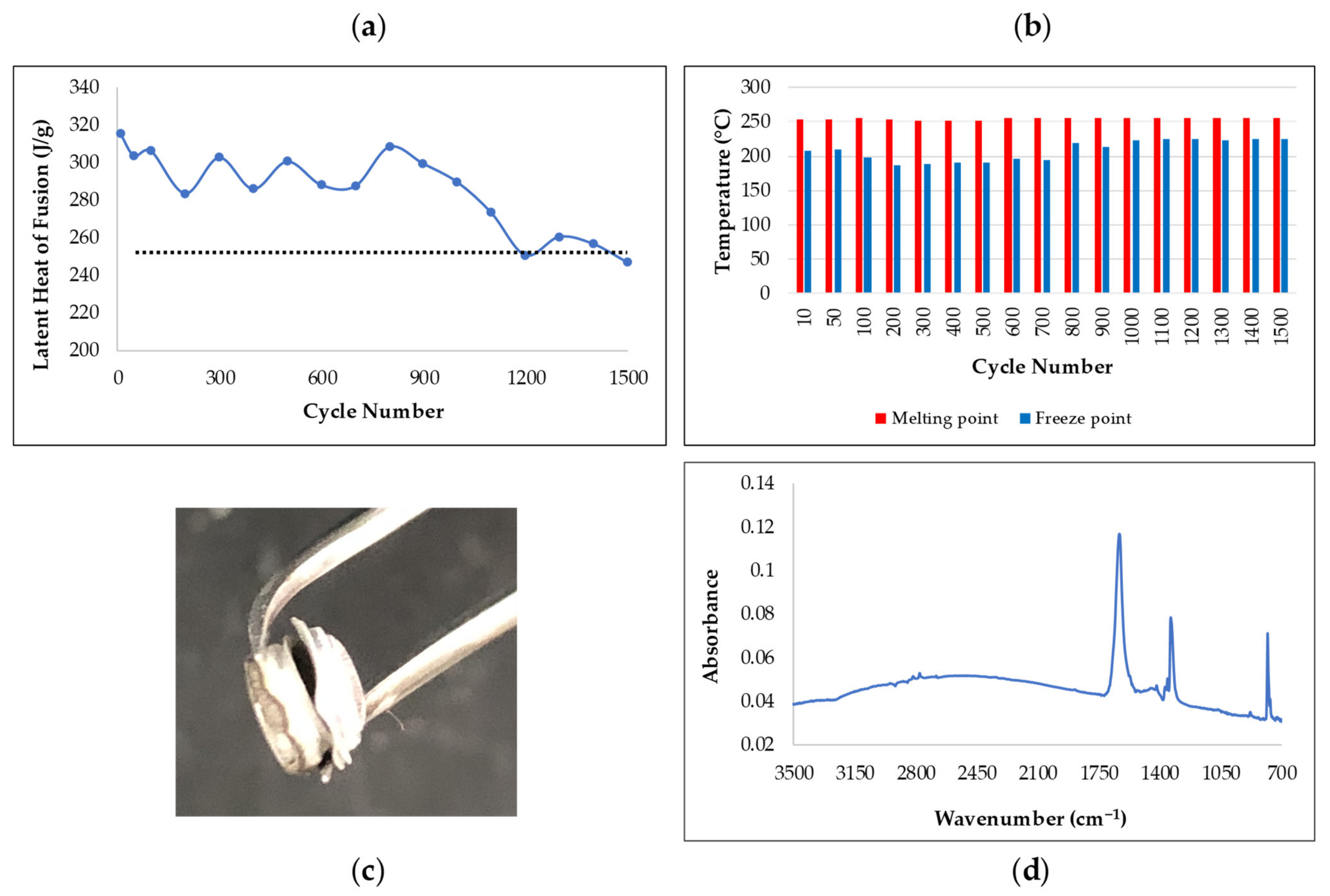
3.1. Latent Heat and Thermal Stability of PCMs

The absolute latent heat of fusion was measured for each formate PCM (Table 1). Sodium formate is the overall focus of the study, due its simplicity, low cost, and high latent heat of fusion. However, its high melting point may make sodium formate storage unattractive for some lower temperature applications, e.g., district heating [14]. For that reason, formate eutectics were also examined, which provide PCMs with lower melting points. As shown in Table 1, the lower melting points are coupled with a lower latent heat value.
Each PCM was thermally cycled in a DSC to measure the reduction in latent heat of fusion over 600 freeze/thaw cycles. Figure 1 shows the latent heat of cycled PCMs vs cycle number up to 600 cycles. Sodium formate maintains a stable latent heat over the course of the experiment (Figure 1a). Sodium/potassium (Figure 1b) exhibits similar stability. Multiple measurements of this PCM showed a loss of latent heat around 60–100 cycles, followed by stable values to 600 cycles. This step change in latent heat is attributed to homogenization of the salt mixture. High temperature eutectic salt PCMs have exhibited similar behavior, as multiple melting and freezing events allow the salt mixture to homogenize into the eutectic formulation [15]. The latent heat of sodium/calcium formate eutectic (Figure 1c) however decreases steadily over the 600-cycle experiment suggesting that this PCM is undergoing chemical degradation. For this reason, further studies concentrated on sodium formate and sodium/potassium formate eutectic PCMs.
The sodium formate was subjected to longer duration cycling experiments to further characterize material stability over a length-scale that was more industrially relevant (>1000 cycles). Figure 2a shows the latent heat degradation over 1500 cycles. The Hf remained stable until approximately cycle 800, whereupon the latent heat steadily decreased to a value of about 85% of the original value as indicated by the black dashed line. This decrease also corresponded to abnormalities in the observed melting and freezing point in the cycles. As shown in Figure 2b, while the melting point stayed relatively unchanged, the freeze point steadily increased from 195 °C to 225 °C. Although the melting and freezing point should be very similar and the wide disparity in melting/freeze points is an indication of supercooling in the PCM, the variation in freeze/thaw behavior is suggestive of possible chemical change in the PCM.The cycling experiment self-terminated as the pan ruptured inside the DSC. Figure 2c is an image showing a ballooned lid, which is partially detached from the pan. The DSC pan ruptured due to an excess of internal pressure within the pan. TA zero hermetic aluminum pans are rated to an internal pressure of 3 psi. The pan was also deformed and slightly crumpled at the base, which may have affected the accuracy of the measurement as heat flow is measured from the post on which the pan sits inside the instrument. A portion of the cycled PCM was collected for FTIR analysis (Figure 2d). The FTIR spectrum peaks at 780.7, 1336.4, and 1631.0 cm−1 all correspond to reported peak positions for sodium oxalate [16]. This chemical conversion from sodium formate to sodium oxalate is likely the cause for the pan rupture and may have been due to impurities in the formate or operation at temperatures that led to thermal decomposition. The thermal degradation of formate to oxalate evolves hydrogen gas as a byproduct [17].

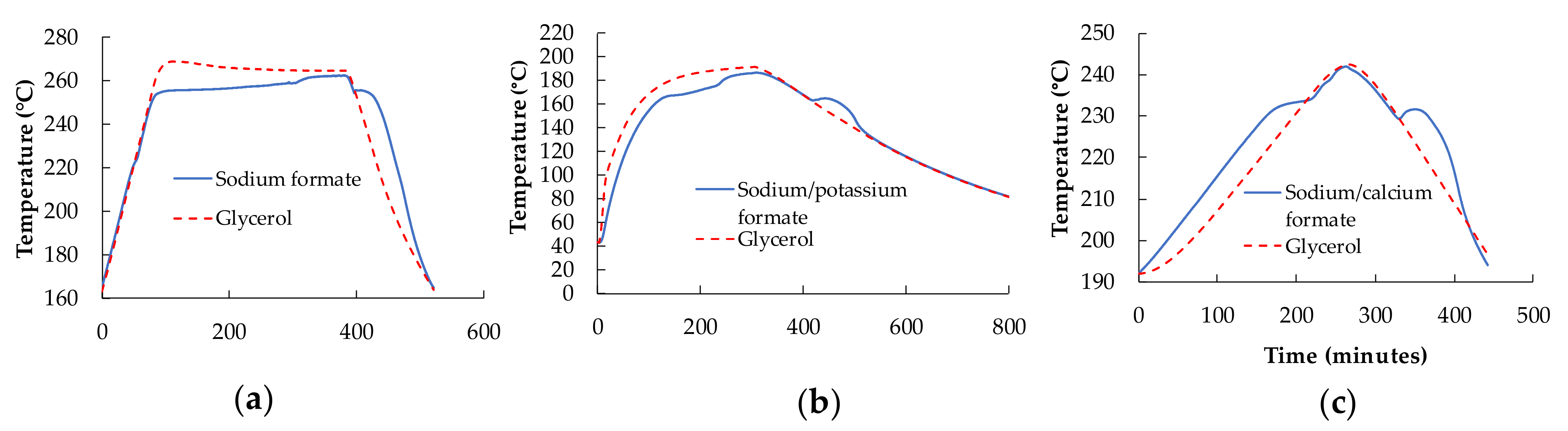
3.2. Supercooling Measurement Using T-History Method

The solidification temperatures of all three PCMs reported by the DSC experiments are lower than their melting temperatures by 20–30 °C. The difference in melting and solidification temperature is called supercooling. It can be the case that the small mass of PCM used in the DSC (~10 mg) cannot provide enough nucleation site for PCM to solidify, and this causes a decrease in solidification temperature [18]. Supercooling is a serious problem for latent heat storage as it effectively lowers the temperature required to trigger PCM freezing, resulting in possible misalignment of the PCM and the heat transfer fluid temperatures. The second problem with supercooling is creation of hysteresis in the freeze/thaw cycle. In the case of sodium/potassium formate, due to supercooling, the molten PCM loses its sensible heat up to 120 °C, whereupon the PCM starts to solidify and liberates latent heat (Figure S1). A portion of the stored energy is lost in reheating the PCM from the temperature at which nucleation occurs to the true phase-change temperature. Various methods have been proposed in literature for reducing supercooling such as seeding (providing a stable crystal of same material), nucleating agents (crystal of other material), and electrical means [18,19]. If needed, these methods result in an increase in complexity and cost of the thermal energy storage system.
The true nature of the supercooling characteristics was explored using a T-history experiment. A large amount of PCM (~50 g) was measured against a glycerol reference to better quantify supercooling in bulk formate PCMs. Figure 3 shows the T-history results for sodium formate (Figure 3a), sodium/potassium formate (Figure 3b), and sodium/calcium formate (Figure 3c).
In each case the supercooling observed was only 2.3 to 2.7 °C, which is 10 to 20 times less than what was observed in the DSC experiments. The supercooling value was identified by the hump observed in the PCM curve relative to the glycerol reference. The height of the hump was recorded as the supercooling value for the given PCM. These results indicate that formate salts are viable in bulk PCM storage systems, as the difference in melting and solidification temperatures was not drastically different. The full indication is that reduction in net temperature and hence lower heat transfer should not be expected in these systems. It should be noted that T-history experiments were only conducted with 50 g of PCM. The supercooling of 2–3 °C ± 0.1 °C may further decrease and may be completely negligible at PCM masses of kilograms and tons.

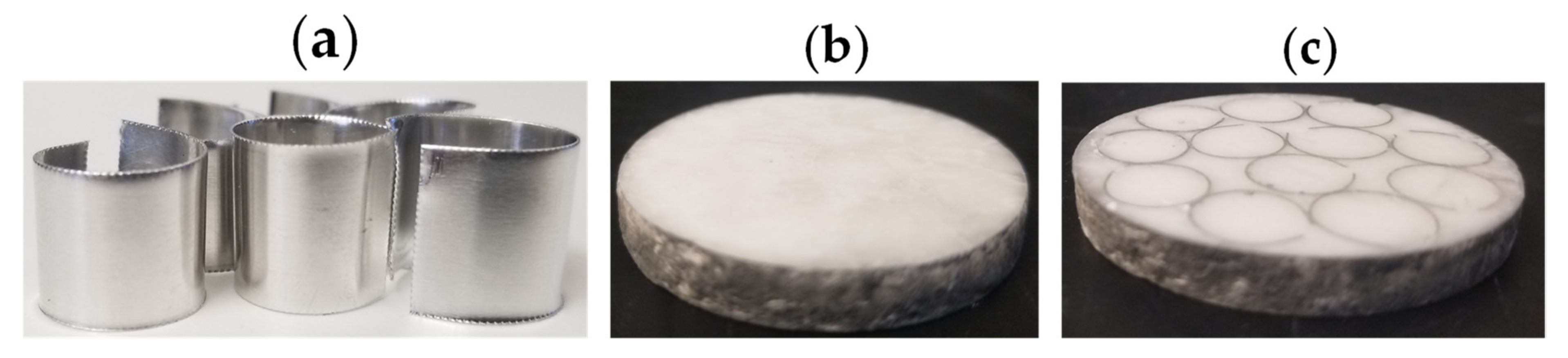
3.3. Thermal Conductivity Enhancement

As with most non-metallic PCMs, the formate salts suffer from a low thermal conductivity that may negatively impact heat flow into and out of the PCM. The implementation of structures to enhance thermal conductivity is essential to system performance, and these structures should ideally provide thermal conduction pathways without impeding convection within the liquid PCM. Thermal enhancement experiments were conducted using sodium/potassium formate eutectic PCM as the lower phase transition temperature simplified the experiment. Aluminum cylinders, simulating aluminum rings, were made from rolled aluminum sheet to act as thermal conductivity enhancers (Figure 4a). First, eutectic PCM was melting inside of a 100 mL glass beaker containing vertically oriented aluminum rings to fill the area of the vessel. Once molten, the beaker was quickly extracted, shaken lightly, and simultaneously cooled from the bottom of the beaker to remove void spaces forming in the solid PCM. The solidified PCM with aluminum rings was then removed from the beaker and polished to create smooth and level faces. The final product was a thin, circular disc (~50 mm in diameter and ~8 mm thick). Figure 4b,c shows the difference in PCM samples with and without aluminum rings.
The thermal conductivity of the PCM samples was measured using a TA DTC-300 guarded heat flow meter, in order to quantify the thermal enhancement provided by the added aluminum rings. Table 2 shows measured thermal conductivity values of the PCM samples as a function of increasing temperature from room temperature to over 100 °C. Aluminum rings provide a significant thermal conductivity enhancement to the eutectic PCM. The experiment may be further improved by increasing the measured sample size. This would decrease the surface to bulk ratio and potentially minimize edge effects, which may alter the measurement. The experimental data collected may better refine future efforts to theoretically model and experimentally study larger scale PCM storage.

3.4. Density Measurements

For most PCMs, the density of solid and liquid phases was different, with the liquid state less dense than the solid. The formates followed this same trend. Table 3 lists the measured density of solid and liquid phases for the formate salts near their melting points. Containment and heat exchanger systems must be designed to accommodate the volume of the PCMs liquid phase, as melting the PCM will result in a volumetric increase.

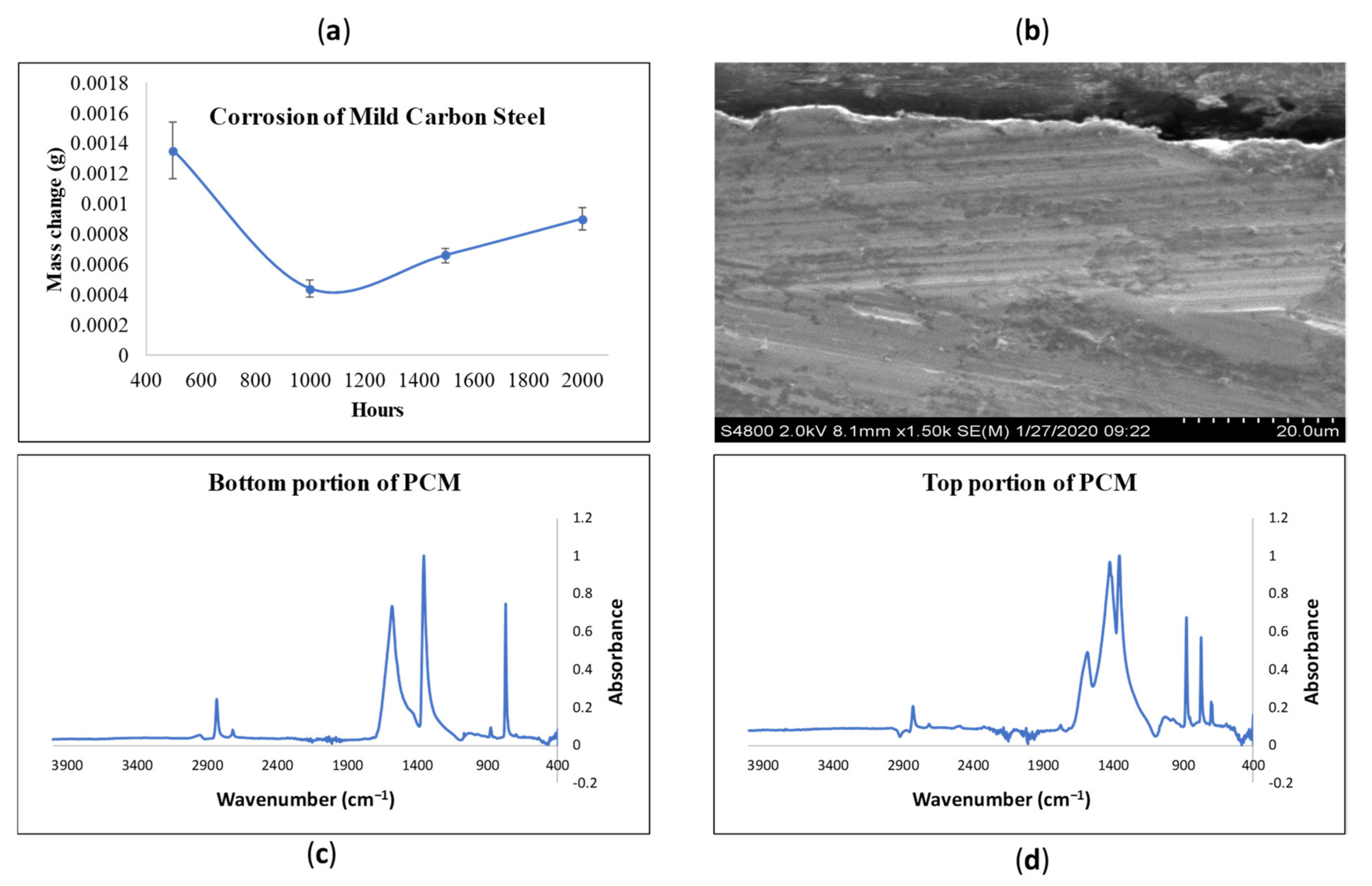
3.5. Corrosion Studies

In order for PCM storage to be economically feasible, storage tanks and heat exchangers must be constructed out of affordable alloys. In this study, mild carbon steel was tested. In order to gain better statistics, 15 carbon steel coupons were prepared and immersed completely into molten sodium formate at 280 °C (Figure 5). A corrosion rate of 45 μm/year or less was targeted. This is the allowed corrosion rate for stress-bearing alloys assuming a 1/16” thick alloy with a 10-year service lifetime as outlined in the American Society of Mechanical Engineers (ASME) Code PV §8.
The coupons were extracted, cleaned to remove all excess PCM, and weighed at 500-h increments. Figure 5a shows the change in mass after each 500-h interval. With known density and area of the coupons, the average final corrosion rate for carbon steel in microns/year of 1.37 μm/year ± 0.45 μm/year (assuming uniform corrosion) was calculated. These encouraging results indicated that carbon steel would be suitable for contact with sodium formate under the allowable code limits stated previously. To confirm the minimal corrosion, one carbon steel coupon from the 2000-h immersion was cross sectioned, mounted in phenolic resin, and polished for high resolution microscopy. The scanning electron microscopy (SEM) images in Figure 5b shows the corrosion interface at the top of the image with the bulk of the coupon extending towards the bottom of the image. There is little evidence of pitting, discoloration, or deposition of new material at the corrosion interface. Furthermore, energy dispersive X-ray spectroscopy (EDS) elemental mapping does not reveal corrosion products at the corrosion interface (Figure S2).
While the coupon did not appear to sustain corrosive damage by contact with the molten salt, the PCM was discolored at the conclusion of the 2000-h experiment. It had changed from white to brown, which increased suspicion of salt degradation. Upper and lower portions of the PCM used in the corrosion studies were sampled and analyzed using FTIR to characterize salt chemistry. Reference FTIR spectra for sodium formate, sodium oxalate, and sodium carbonate were acquired from the NIST Chemistry WebBook database and used to identify chemical species in the samples (Figure S3). Figure 5c is an FTIR spectrum of the PCM sample from the bottom of the containment vessel (i.e., furthest from the atmosphere). The spectrum matches that of sodium formate, indicating that no PCM degradation occurred in the region isolated from atmosphere. Figure 5d is FTIR data taken from PCM sampled from the atmosphere-exposed surface of the containment vessel. This shows clear evidence of PCM degradation to sodium oxalate and carbonate, as indicated by the growth of peaks at approximately 1354 cm−1 (oxalate) and 1420 cm−1, 876 cm−1 and 700 cm−1 (carbonate) (Figure S3). Figure 2d showed PCM decomposition that was arrested at oxalate formation. However, Figure 5d demonstrates that continued exposure of molten formate salt to atmosphere accelerates the irreversible decomposition of formate to oxalate and carbonate. These results further support the hypothesis that oxygen and moisture should be avoided to maintain formate stability at PCM operating temperatures [17].

4. Conclusions

This study assesses the thermochemical properties of formate salts as potential latent heat phase change materials. Characterization of sodium formate, sodium/potassium formate, and sodium/calcium formate PCMs was conducted, documenting the latent heat and melting point of each PCM. Thermal cycling to 600 cycles showed stable latent heat values for sodium formate and sodium/potassium formate, whereas sodium/calcium formate latent heat steadily degraded. Extended thermal cycling of sodium formate revealed a decrease in latent heat of fusion above 800 cycles. Post-test analysis revealed gas evolution from the sample and the formation of sodium oxalate. Further studies are proposed to explore the long-term stability of the formate salts and the influence of atmosphere and temperature on PCM stability.
Supercooling of the three formate PCMs was characterized using the T-history method. Each PCM exhibited 2–3 °C supercooling in the 50-g T-history testing, which was significantly smaller than the 20–30 °C supercooling observed via 10-mg DSC samples. Thermal conductivity enhancement of 7× was achieved by embedding aluminum rings into the PCM. The corrosive resistance of mild carbon steel was assessed in molten sodium formate for up to 2000 h. Little corrosion was noted on the steel; however, the free surface of the sodium formate showed some degradation to sodium oxalate and carbonate. This result further enforces the need to prevent exposure of the PCM to ambient air. Similar to sodium formate, sodium/potassium formate PCM would be of interest for follow-on study, due to its apparent thermal stability (up to 600 cycles) and applicability for lower temperature PCM storage systems, which likely aids its stability.

Supplementary Materials

The following are available online at https://www.mdpi.com/1996-1073/14/3/765/s1. Figure S1: DSC graph showing the consequences of supercooling: reduction in net temperature, lower total heat transfer. Figure S2: Energy dispersive X-ray spectroscopy (EDS) maps of spectra of cross-sectioned carbon steel coupon. The corrosion interface is located near the top of the image with the bulk of the coupon extending toward the bottom of the image. The coupon is mounted in a phenolic resin, which accounts for the high concentration of carbon and oxygen at the top of the image. There is no evidence of chromium-, iron-, or nickel-containing corrosion products at the corrosion interface. Figure S3: FTIR Reference spectra of sodium formate (left), sodium oxalate (middle), and sodium carbonate (right). References taken from the NIST Chemistry WebBook spectral database.

Author Contributions

Formal analysis, S.G., P.S. and J.N.; funding acquisition, C.T. and J.N.; investigation, S.G.; project administration, J.N.; writing—original draft, S.G.; writing—review and editing, S.G., P.S., C.T. and J.N. All authors have read and agreed to the published version of the manuscript.

Funding

This research was funded by U.S. Department of Energy, Topic 2: Low Cost Thermal Energy, Solar Desalination FOA: DE-FOA-0001778 in conjunction with Sunvapor, Inc. 145 N Sierra Madre Blvd., Unit 3, Pasadena, CA 91107.

Acknowledgments

This work was authored in part by the National Renewable Energy Laboratory, operated by Alliance for Sustainable Energy, LLC, for the U.S. Department of Energy (DOE) under Subcontract ADJ-9-92133-01 under Prime Contract No. DE-AC36-08GO28308. Funding provided by DOE Office of Energy Efficiency and Renewable Energy (EERE). The views expressed in the article do not necessarily represent the views of the DOE or the U.S. Government. The publisher, by accepting the article for publication, acknowledges that the U.S. Government retains a nonexclusive, paid-up, irrevocable, worldwide license to publish or reproduce the published form of this work, or allow others to do so, for U.S. Government purposes. The authors gratefully acknowledge Noah Klammer for performing initial screening experiments of various PCM candidates and Thao Truong for assisting in the corrosion studies. Sunvapor, Inc. is acknowledged for their technical input and discussions.

Conflicts of Interest

The authors declare no conflict of interest.

References

  1. McMillan, C.A.; Ruth, M. Using Facility-Level Emissions Data to Estimate the Technical Potential of Alternative Thermal Sources to Meet Industrial Heat Demand. Appl. Energy 2019, 239, 1077–1090. [Google Scholar] [CrossRef]
  2. Turchi, C.S.; Kurup, P.; Zhu, G. Revisiting Parabolic Trough Concentrators for Industrial Process Heat in the United States. In Proceedings of the ASME 2016 Power Conference collocated with the ASME 2016 10th International Conference on Energy Sustainability and the ASME 2016 14th International Conference on Fuel Cell Science, Engineering and Technology, Charlotte, NC, USA, 26–30 June 2016. [Google Scholar]
  3. Jin, X.; Hu, H.; Shi, X.; Zhou, X.; Zhang, X. Comparison of Two Numerical Heat Transfer Models for Phase Change Material Board. Appl. Therm. Eng. 2018, 128, 1331–1339. [Google Scholar] [CrossRef]
  4. Sharan, P.; Turchi, C.; Kurup, P. Optimal Design of Phase Change Material Storage for Steam Production Using Annual Simulation. Sol. Energy 2019, 185, 494–507. [Google Scholar] [CrossRef]
  5. Fox, D.B.; Sutter, D.; Tester, J.W. The Thermal Spectrum of Low-Temperature Energy Use in the United States; Cornell University: Ithaca, NY, USA, 2011. [Google Scholar]
  6. Pereira da Cunha, J.; Eames, P. Thermal Energy Storage for Low and Medium Temperature Applications Using Phase Change Materials—A Review. Appl. Energy 2016, 177, 227–238. [Google Scholar] [CrossRef] [Green Version]
  7. Xu, B.; Li, P.; Chan, C. Application of Phase Change Materials for Thermal Energy Storage in Concentrated Solar Thermal Power Plants: A Review to Recent Developments. Appl. Energy 2015, 160, 286–307. [Google Scholar] [CrossRef]
  8. Pielichowska, K.; Pielichowski, K. Phase Change Materials for Thermal Energy Storage. Prog. Mater. Sci. 2014, 65, 67–123. [Google Scholar] [CrossRef]
  9. Nakaso, K.; Teshima, H.; Yoshimura, A.; Nogami, S.; Hamada, Y.; Fukai, J. Extension of Heat Transfer Area Using Carbon Fiber Cloths in Latent Heat Thermal Energy Storage Tanks. Chem. Eng. Process. Process Intensif. 2008, 47, 879–885. [Google Scholar] [CrossRef]
  10. Shukla, A.; Buddhi, D.; Sawhney, R.L. Thermal Cycling Test of Few Selected Inorganic and Organic Phase Change Materials. Renew. Energy 2008, 33, 2606–2614. [Google Scholar] [CrossRef]
  11. Farid, M.M.; Khudhair, A.M.; Razack, S.A.K.; Al-Hallaj, S. A Review on Phase Change Energy Storage: Materials and Applications. Energy Convers. Manag. 2004, 45, 1597–1615. [Google Scholar] [CrossRef]
  12. Zhang, W.; Chen, X.; Liu, Z.; Sun, W.; Liu, S. Formation of Sodium Oxalate by Thermal Decomposition of Sodium Formate. J. Beijing Uni. Chem. Tech. 2007, 34, 566–569. [Google Scholar]
  13. Yinping, Z.; Yi, J.; Yi, J. A Simple Method, the History Method, of Determining the Heat of Fusion, Specific Heat and Thermal Conductivity of Phase-Change Materials. Meas. Sci. Technol. 1999, 10, 201–205. [Google Scholar] [CrossRef]
  14. Gadd, H.; Werner, S. Achieving Low Return Temperatures from District Heating Substations. Appl. Energy 2014, 136, 59–67. [Google Scholar] [CrossRef] [Green Version]
  15. Gomez, J.C. High-Temperature Phase Change Materials (PCM) Candidates for Thermal Energy Storage (TES) Applications; NREL/TP-5500-51446; National Renewable Energy Laboratory: Denver W Pkwy, CO, USA, 2011. [Google Scholar] [CrossRef] [Green Version]
  16. Acree, W.E.; Chickos, J.S. Evaluated Infrared Reference Spactra. In NIST Chemistry WebBook, NIST Standard Reference Database Number 69; Linstrom, P.J., Mallard, W.G., Eds.; National Institute of Standards and Technology: Gaithersburg, MD, USA, 2018. [Google Scholar] [CrossRef]
  17. Meisel, T.; Halmos, Z.; Seybold, K.; Pungor, E. The Thermal Decomposition of Alkali Metal Formates. J. Therm. Anal. 1975, 7, 73–80. [Google Scholar] [CrossRef]
  18. Beaupere, N.; Soupremanien, U.; Zalewski, L. Nucleation Triggering Methods in Supercooled Phase Change Materials (PCM), a Review. Thermochim. Acta 2018, 670, 184–201. [Google Scholar] [CrossRef]
  19. Cui, W.; Yuan, Y.; Sun, L.; Cao, X.; Yang, X. Experimental Studies on the Supercooling and Melting/Freezing Characteristics of Nano-Copper/Sodium Acetate Trihydrate Composite Phase Change Materials. Renew. Energy 2016, 99, 1029–1037. [Google Scholar] [CrossRef]
Figure 1. (a) Latent heat (Hf) as a function of cycle number up to 600 cycles for sodium formate, (b) sodium/potassium formate, and (c) sodium/calcium formate.
Energies 14 00765 g001
Figure 2. (a) Latent heat of sodium formate as a function of thermal cycles, (b) plot of melting and freezing points of sodium formation as a function of thermal cycles, (c) Image of ruptured differential scanning calorimetry (DSC) pan, and (d) FTIR spectrum of cycled sodium formate phase change material (PCM), showing degradation to sodium oxalate.
Energies 14 00765 g002
Figure 3. T-history experimental results of PCM vs. glycerol reference: (a) sodium formate, (b) sodium/potassium formate, and (c) sodium/calcium formate. The temperature difference between the onset of the hump in the cool-down curve and the maximum rise in the hump represents the degrees of supercooling [13].
Energies 14 00765 g003
Figure 4. (a) Image of aluminum 6061 rings, (b) image of PCM without aluminum rings, (c) image of eutectic PCM with aluminum rings PCM discs were nominally 8 mm thick and 50 mm in diameter.
Energies 14 00765 g004
Figure 5. (a) Corrosion of mild carbon steel in molten sodium formate. Corrosion data are expressed as average mass change of coupons with standard error over 2000 h, measured at 500-h increments. (b) SEM images of cross sectioned carbon steel coupon after 2000-h immersion in molten sodium formate. Magnification 1500×. (c) FTIR of the bottom portion of the PCM after corrosion experiment was completed. (d) FTIR of the top portion of the PCM after corrosion experiment was completed.
Energies 14 00765 g005
Table 1. Measured melting point and latent heat of fusion of three target formate PCMs.
Sodium FormateSodium/Calcium FormateSodium/Potassium Formate
Average Hf (J/g)252.3 ± 0.7171.1 ± 0.7134.0 ± 1.1
Average melting point (°C)256.5 ± 2.8229.4 ± 0.1155.3 ± 0.3
Table 2. Thermal conductivity enhancement of sodium/potassium formate PCM from Al 6061 rings.
Temperature (°C)Thermal Conductivity (W/m·K) without RingsThermal Conductivity (W/m·K) with Rings
320.423.5
570.443.7
820.463.7
1070.473.7
Table 3. Solid and liquid density of formate PCMs.
PCMLiquid Density (g/mL)Solid Density (g/mL)
Sodium/potassium formate1.671.72
Sodium/calcium formate1.611.76
Sodium formate1.501.64
Publisher’s Note: MDPI stays neutral with regard to jurisdictional claims in published maps and institutional affiliations.

