Article

Torque Ripple Suppression of PMSM Based on Robust Two Degrees-of-Freedom Resonant Controller

1
Changchun Institute of Optics, Fine Mechanics and Physics, Chinese Academy of Sciences, Changchun 130033, China
2
University of Chinese Academy of Sciences, Beijing 100049, China
*
Author to whom correspondence should be addressed.
Energies 2021, 14(4), 1015; https://doi.org/10.3390/en14041015
Submission received: 13 January 2021 / Revised: 10 February 2021 / Accepted: 11 February 2021 / Published: 15 February 2021

Abstract

:
This paper concentrates on a robust resonant control strategy of a permanent magnet synchronous motor (PMSM) for electric drivers with model uncertainties and external disturbances to improve the control performance of the current loop. Firstly, to reduce the torque ripple of PMSM, the resonant controller with fractional order (FO) calculus is introduced. Then, a robust two degrees-of-freedom (Robust-TDOF) control strategy was designed based on the modified resonant controller. Finally, by combining the two control methods, this study proposes an enhanced Robust-TDOF regulation method, named as the robust two degrees-of-freedom resonant controller (Robust-TDOFR), to guarantee the robustness of model uncertainty and to further improve the performance with minimized periodic torque ripples. Meanwhile, a tuning method was constructed followed by stability and robust stability analysis. Furthermore, the proposed Robust-TDOFR control method was applied in the current loop of a PMSM to suppress the periodic current harmonics caused by non-ideal factors of inverter and current measurement errors. Finally, simulations and experiments were performed to validate our control strategy. The simulation and experimental results showed that the THDs (total harmonic distortion) of phase current decreased to a level of 0.69% and 5.79% in the two testing environments.

1. Introduction

Permanent magnet synchronous motors (PMSMs) have been widely employed in servo control systems, such as in electrical vehicles, numerical control machines, and robotic fields, owing to its advantages of high power density, low electric power loss, and small structural size [1,2,3,4]. However, parameter mismatching, nonlinearity of the controlled model, and uncertain disturbances inevitably exist in the PMSM servo system, which decreases the tracking performance and stability [5].
To overcome the drawbacks of PMSMs, several useful control theories such as sliding mode control (SMC), model predictive control (MPC), and active disturbance rejection control (ADRC) have been developed, which are represented in references [6,7,8]. Compared with traditional PID controller, these control methods can improve the robustness and tracking performance in different aspects. However, some of these control methods rely on ideal assumptions and large computational amounts, which limits these advanced control methods in industry application to some degree [9,10].
A robust two degrees-of-freedom control (Robust-TDOF) strategy has been proposed by Umeno [11,12]. This control method was established by using a free parameter within the set of strictly proper and stable rational functions, which has the advantages of simplicity, providing desired dynamic responses and strong robustness to model uncertainty and unknown disturbances. Therefore, it has been implemented in other servo control systems [12,13].
On the other hand, it is pointed out that this control method is considered as obsolete, but it provides a practical solution of the robust control in the electric drive field [13]. The robustness of Robust-TDOF, with respect to model mismatch and external disturbance, has been verified by means of experimental verification in references [14,15]. Despite its advantages, this control method is only designed for the speed loop control of a DC motor. With the development of power electronic technology especially the field-oriented methodology decoupling control of torque and flux, the servo system of PMSM can be constructed by the control of two first linear order plants with a PI (proportional–integral) controller. Just like the above-mentioned advanced control methods, the Robust-TDOF control method for PMSM has been extended in the current or speed loops to replace a PI controller [16].
Considering the non-liner electrical dynamics, the stability of the Robust-TDOF control method applied in PMSMs with round and salient rotors has been discussed in reference [17]. The resulting stability condition provides an idea of tuning the parameters of the Robust-TDOF controller. It should be note that though the design guideline of tradition frequency domain Robust-TDOF controller have been thoroughly investigated [11,12]. It was demonstrated that the Robust-TDOF filters (especially the Q filter) serve as the key component in the controller design, which directly affects the robust performance. The Robust-TDOF controller can effectively suppress these slow-time varying disturbances by setting an appropriate bandwidth of the filter. However, due to the non-linear factors of inverter, current measurement errors and periodic disturbances, i.e., harmonic components, will occur in PMSM operation [4]. These periodic disturbances (conventionally occurring several times more often as the fundamental frequency) may be near or outside of the corner frequency of the Q filter (corresponding to the bandwidth), which decreases the control performance and results in torque ripple when classical a Robust-TDOF controller applied to PMSM. The magnitude of these high frequency components with periodic characteristics is pretty small, which would be insignificant. Nevertheless, it should be taken into consideration especially in a high-performance drive system.
To suppress the periodic disturbance, some control methods have been proposed. An iterative learning control (ILC) method by combining with sliding mode control (SMC) or model predictive control (MPC) has been proposed to minimize the repetitive disturbance [18,19]. However, this control method may result in large overshoots during the transient process before the iteration error converges [20]. A repetitive control (RC) method has been designed in a current loop to compensate the low- and high-frequency harmonics, but it needed a certain storage space and increased the computational burden [21]. Additionally, a control method using two decoupled PI controllers has been employed to minimize the periodic torque ripples [22]. This strategy constitutes a simple and practical option to suppress the torque ripples. However, as the study describes its disadvantage, the parameter variation is not considered.
Resonant controller is a popular control method used to deal with AC signals, which has the advantages of small computation and easy digital implementation. Therefore, it is widely used in grid-connected inverters [23] and doubly fed induction generators [24]. It is a common understanding that the resonant controller can suppress the harmonics and reduce torque ripple. However, the structure of parallel connection of multi-resonant terms has been adopted in more novel works [25,26]. Different from the previous study, a series connect structure has been designed in this paper, which is more straightforward and simpler. Meanwhile, the fractional-order calculus is introduced to the resonant term, which can further improve harmonic suppression performance (see references [27,28,29,30,31] for detailed information about the fractional order system).
Consequently, an enhanced Robust-TDOF control strategy named as Robust-TDOFR controller is proposed by embedding the series resonant terms. Furthermore, based on the derived stability and robust stability condition, a simple tuning method is provided, and possible trade-offs are explored. Finally, the proposed control method is applied to current loop to eliminate the slow-varying and unmodeled periodic disturbances.
The outline of paper is organized as follows. Section 2 gives a dynamic model of the PMSM, and Section 3 demonstrates the performance analysis and design process of the developed control method. Section 4 presents the simulation and experimental results of the proposed algorithm. Finally, our findings and conclusions are summarized in Section 5.

2. Dynamic Model of a PMSM

The mathematical model of the PMSM in the rotating reference frame can be expressed as follows [8]:
{ d i q d t = 1 L q ( u q R q i q n p ω L d i d n p ω ψ f ) d i d d t = 1 L d ( u d R d i d + n p ω L q i q ) d ω d t = 1 J ( T e T f T L ) d θ e d t = n p ω
in which
{ T e = 1.5 n p [ ψ f i q + ( L d L q ) i d i q ] T f = B ω ω
where i q and i d denote the state currents in d- and q-axes; u d and u q are the stator voltages; and L d , L q , R d and R q represent the stator inductance and resistance along the d–q-axis. T e , T f , T L , ψ f , n p , B ω , ω and θ e are the electromagnetic torque, friction torque and load torque, flux linkage, number of pole pairs, frictional coefficient, mechanical speed and electrical angle, respectively.
If the surface-mounted PMSM is selected, it indicates:
{ L d = L q T e = 1.5 n p ψ f i q

3. Design of Robust-TDOFR Controller

We start with a brief description of the traditional Robust-TDOF controller to analyze its main advantages and disadvantages; this drawbacks motivated us to design the proposed Robust-TDOFR controller, which will be detailed in this section.

3.1. Preliminaries of Robust-TDOF Controller

Figure 1 demonstrates the control diagram of Robust-TDOF controller which utilizes the controlled plant model as an explicit part of controller parameters. The Robust-TDOF can provide strong robustness with respect to model uncertainty and external disturbance and guarantee desired dynamic response by using the serial compensator C A ( s ) and detector C B ( s ) [11,32]. G p ( s ) is the model of control plant.
Based on two degrees-of-freedom control methodology, C A ( s ) and C B ( s ) have the following expressions:
{ C A ( s ) = G r y ( s ) ( 1 G r y ( s ) ) G p n ( s ) ( 1 Q ( s ) ) C B ( s ) = Q ( s ) ( 1 Q ( s ) ) G p n ( s )
where G r y ( s ) = 1 / ( τ s + 1 ) is the preset dynamic behavior, and τ is the time constant associated with the dynamic response. G p n ( s ) = 1 / ( L 0 s + R 0 ) is the nominal model of control plant; L 0 and R 0 are the parameters of the nominal model, which can be determined by a crude estimation; Q ( s ) is the internal model filter, given by:
Q ( s ) = 2 λ s + 1 ( λ s ) 2 + 2 λ s + 1
where λ is a parameter determining the robustness of Robust-TDOF.
Based on Equations (4) and (5), the C A ( s ) and C B ( s ) are derived as follows:
{ C A ( s ) = ( ( τ s ) 2 + 2 λ s + 1 ) ( L 0 s + R 0 ) τ s 3 C B ( s ) = 2 λ L 0 s 2 ( s + 1 2 λ ) ( s + R 0 L 0 )
According to Equation (5), and using the inverse Laplace transform, the control law u I M C ( t ) of Robust-TDOF can be expressed as:
u I M C ( t ) = k p e e ( t ) + k i e 1 0 t e ( t ) d t + k i e 2 0 t [ 0 θ e ( θ ) d θ ] d t + k i e 3 0 t [ 0 θ [ 0 f e ( f ) d f ] d θ ] d t k p y i ( t ) k i y 1 0 t i ( t ) d t k i y 2 0 t [ 0 θ i ( θ ) d θ ] d t
where e ( t ) = i r e f i ( t ) , k p e = L 0 λ , k i e 1 = L 0 τ ( 1 λ + R 0 L 0 ) , k i e 2 = L 0 τ ( 1 λ 2 + 2 R 0 L 0 λ ) , k i e 3 = R 0 τ λ 2 , k p y = 2 L 0 λ , k i y 1 = L 0 ( 1 λ 2 + 2 R 0 L 0 λ ) , k i y 2 = R 0 λ 2 .
The integral links in Equation (7) may result in iterated integral overflow. To avoid this problem, the following state variables are defined:
z 1 = e ( t ) ,   z 2 = 0 t e ( t ) d t i r e f α 1 k p e ( k i e 1 + k i y 1 ) ,   z 3 = 0 t [ 0 r e ( δ ) d δ i r e f γ 1 k i y 1 k i e 2 + k i y 2 ] d r i r e f α 2 k p y ( k i e 2 + k i y 2 ) , z 4 = 0 t { 0 r [ 0 d e ( θ ) d θ i r e f k i y 2 k i e 3 ] d δ γ 2 k i y 1 k i e 3 i r e f } d r R i r e f k i e 3 α 3 i r e f k p y k i e 3
where α 1 , γ 1 R + and α 2 , α 3 , γ 2 R . If α 1 , α 2 , α 3 , γ 1 and γ2 satisfy the following condition:
{ α 1 + α 2 + α 3 = 1 γ 1 + γ 2 = 1 α 1 k p e k i e 1 + k i y 1 = k i y 2 k i e 3 = γ 1 k i y 1 k i e 2 + k i y 2 α 2 k p y ( k i e 2 + k i y 2 ) = γ 2 k i y 1 k i e 3
We can write:
z ˙ 4 = z 3 ,   z ˙ 3 = z 2 ,   z ˙ 2 = z 1
Then, the control law in Equation (7) can be expressed as:
u I M C ( t ) = ( k p e + k p y ) z 1 + ( k i e 1 + k i y 1 ) z 2 + ( k i e 2 + k i y 2 ) z 3 + k i e 3 z 4

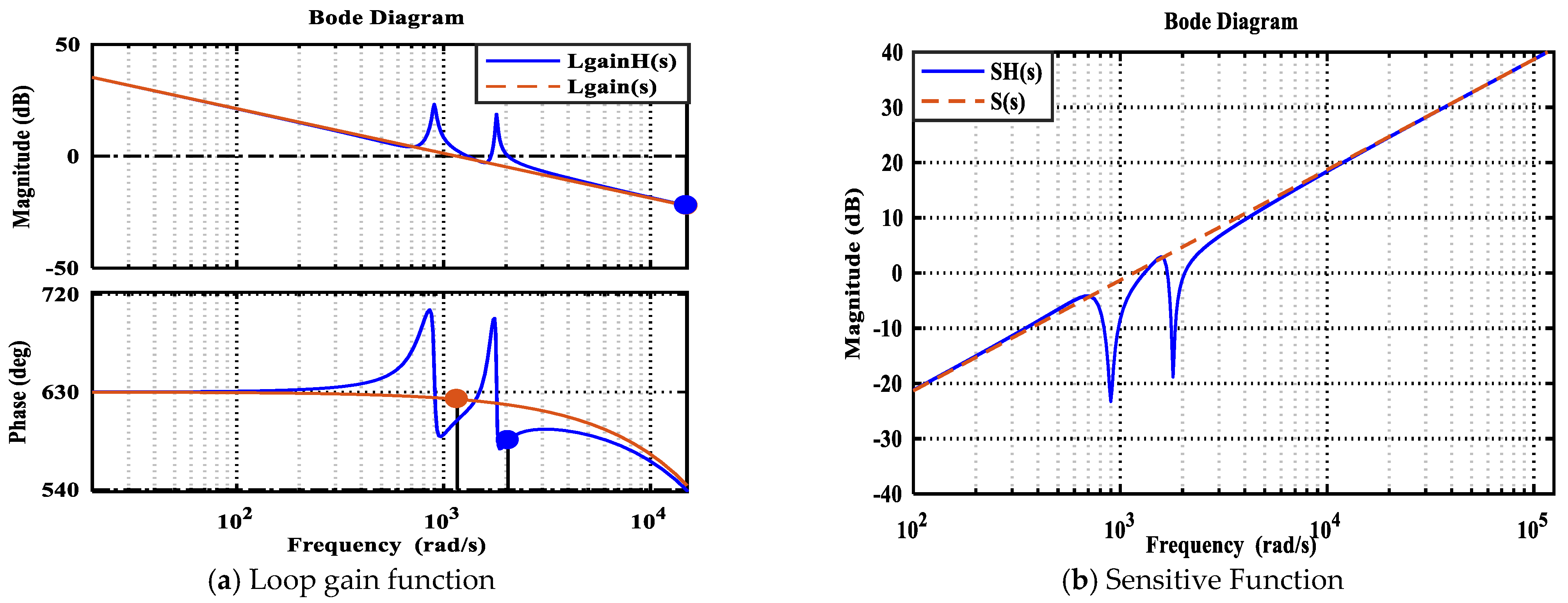
3.2. Robust Performance Analysis of Robust-TDOF

If the error between the actual model and nominal model occurs, i.e., G p ( s ) = G p n ( s ) ( 1 + Δ G p n ( s ) ) , the closed transfer function with Robust-TDOF can be obtained as:
i ( s ) [ 1 + ( 1 Q ( s ) ) D G p n ( s ) ] G r y ( s ) i r e f ( s ) + ( 1 Q ( s ) ) ( 1 G r y ( s ) ) d ( s )
where i r e f ( s ) and i ( s ) represent the input and output signals of i r e f and i ( t ) , respectively.
The lumped disturbance and uncertainty L d ( s ) can be denoted as:
L d ( s ) ( 1 Q ( s ) ) [ Δ G p n ( s ) + ( 1 G r y ( s ) ) d ( s ) ]
Here, ( 1 Q ( s ) and ( 1 G r y ( s ) ) are the high pass filters, and their cut off frequencies satisfied 1 / λ 1 / τ . The preset dynamic response can be regarded as a given tracking trajectory to be designed; hence, τ is a known parameter rather than tuning gain. The robustness of Robust-TDOF is only affected by the λ tuning.
To ensure satisfactory robustness of Robust-TDOF, the high pass filter 1 Q ( s ) should be maintained enough transients decay rate in the bandwidth of ( 0 , 1 / τ ) , i.e., | ( 1 Q ( j ω ) ) | = 0 for ω = 0 and | ( 1 Q ( j ω ) ) | > 0 for ω > 0 . Therefore, the external disturbance can be attenuated. Meanwhile, it is apparently observed that the attenuation ability decreases with the increase in ω , because the magnitude difference between | ( 1 Q ( j ω ) ) | and 0 dB line decreases depending on the bandwidth of the Q ( s ) . The frequency domain analysis indicates λ should be selected as small as possible to achieve a good robust performance. However, this will introduce large high frequency noise to control system [11,17]. In practice, choosing λ is balanced between robustness and noise suppression, which limits the anti-disturbance ability.

3.3. Disturbance Suppression with Resonant Controller

When the external disturbance is a constant, the Robust-TDOF can ensure satisfactory anti-disturbance ability. However, the traditional Robust-TDOF controller has difficult to attenuate to the high frequency periodic disturbances, owing to the fact that these high frequency periodic signals may be outside the bandwidth of 1 Q ( s ) . To further improve the anti-disturbance ability of Robust-TDOF, the resonant controller with series connection structure is embedded in the forward path, which has the following expression:
[ C A ( s ) C B ( s ) ] = [ H A ( s ) 0 0 H B ( s ) ] [ C A ( s ) C B ( s ) ]
H A ( s ) and H B ( s ) are the periodic disturbance suppression controllers to be designed. C A ( s ) and C B ( s ) represent the modified controllers.
According to Equation (4) and Equation (13), the closed transfer function of current loop can be obtained as:
i ( s ) = G r y ( s ) H A ( s ) i r e f ( s ) T ( s ) + ( 1 Q ( s ) ) ( 1 G r y ( s ) ) G p ( s ) d ( s ) T ( s )
where:
Τ ( s ) = ( 1 Q ( s ) ) ( 1 G r y ( s ) ) + G r y ( s ) H A ( s ) + ( 1 G r y ( s ) ) Q ( s ) H B ( s )
If H A ( s ) = H B ( s ) = H ( s ) , Equation (15) can be derived as:
T ( s ) = ( 1 Q ( s ) ) ( 1 G r y ( s ) ) ( 1 H ( s ) ) + H ( s )
According to the analysis in Section 3.2, ( 1 Q ( s ) ) is a high pass filter; hence, when ω 1 / τ , it is not difficult to verify that:
[ ( 1 Q ( s ) ) ( 1 G r y ( s ) ) ( 1 H ( s ) ) ] H ( s )
Then, Equation (14) can be further simplified as:
i ( s ) = G r y ( s ) i r e f ( s ) + ( 1 Q ( s ) ) ( 1 G r y ( s ) ) G p ( s ) d ( s ) H ( s )
According to Equation (18), it can be observed that the preset dynamic response remains unaffected by the designed controller owing to the filter ( 1 Q ( s ) ) . This provides an approach that can independently design the high frequency periodic disturbance suppression controller. Moreover, it can be also observed that the d ( s ) can be attenuated if d ( s ) is in the bandwidth of (0,1/ λ ). However, the current loop contains some high frequency harmonics components, i.e., the sixth and the twelfth, which may be outside the bandwidth of attenuation frequencies or closed to the cutoff frequency. In such cases, these harmonic components cannot be effectively suppressed.
Conventionally, the high frequency periodic disturbance in current loops can be expressed as Fourier series as follows:
d ( t ) = n = 1 ρ n c o s ( n ω h ) + n = 1 δ n s i n ( n ω h )
where ρ n and δ n are the amplitudes of disturbance, and ω h is the electrical angular frequency.
Based on Laplace transform, Equation (19) can be derived as:
d ( s ) = n = 1 ρ n s + δ n n ω h s 2 + ( n ω h ) 2
To attenuate the periodic disturbances of d ( s ) and avoid unstable poles at s = ± j n ω h , the H ( s ) should be chosen as follows:
H ( s ) = F ( s ) n = 1 R n ( s ) = k s α ( ϑ s α + 1 ) n = 1 2 s s 2 + 2 ξ s + ( n ω h ) 2
where F ( s ) is the fractional order operator introduced to improve the ability of periodic disturbance suppression, and α ( 0 , 1 ) ; ϑ = 1 / ( 2 π f ) is the time constant; f is the sampling frequency of current loop. R n ( s ) represents the controller used to suppress nth harmonics; k is the tuning gain, and ξ is the damping cutoff frequency satisfied ξ n ω h .
By combining Equation (7) and Equation (21), the Robust-TDOF with a series resonant controller can be expressed as:
U ( s ) = ( 1 + H ( s ) ) ( C A ( s ) C B ( s ) )
The corresponding control structure is shown in Figure 2, and the added new controller is enclosed by the blue dashed rectangle.

3.4. Parameters Analysis of the Resonant Controller

According to the analysis in reference 25, the sixth and twelfth harmonics are the dominant components of periodic disturbances. Thus, the center frequencies can be first determined by 6 ω h = 900   r a d / s and 12 ω h = 1800   r a d / s . The sampling frequency f of the current loop is 10 kHz, and the constant value ϑ can be calculated by ϑ = 1 / ( 2 π f ) = 1.59   ×   10 5 . k , ξ and α are essential parameters which determine the periodic disturbance suppress ability. To analyze the effect of the three parameters on the periodic disturbance suppression, characteristics of 1 + H ( s ) with different values of k , ξ and α are investigated.
Figure 3a demonstrates the amplitude-phase characteristics of 1 + H ( s ) with increasing k , with α and ξ remaining at 0.1 and 10 rad/s, respectively. It can be observed that the larger k can ensure larger gain at resonant frequencies. However, the bandwidth is not changed. Figure 3b shows the characteristics of resonant gain and bandwidth with the variation of ξ when k = 10 and α = 0.1 . The bandwidth increases as ξ increases; however, this will reduce the gain. In practical resonant controller design, ξ values of 5~15 rad/s have been found to provide a good tradeoff [33]. Figure 3c exhibits the Bode diagram of 1 + H ( s ) with α sweeping, and k and ξ maintaining the constant values of 5 and 10 rad/s, respectively. It can be seen that the bandwidth and resonant gain are improved as α increases. Furthermore, it is interesting to note that the amplitude of resonant gain at 1800   rad / s is higher than that at 900   rad / s , which is quite different from the k and ξ tuning. The effect of α on the resonant gain can be described as k ( n ω h ξ ) ( n ω h ) α . The resonant gain increases exponentially with the resonant frequency, and the increase rate is the fraction order term α . α cannot be set as very large, because the characteristics of other frequencies may change.

3.5. Robust-TDOF with Resonant Controller (Robust-TDOFR) Analysis

The resonant controllers were used in the control system, which will result in oscillation and decrease the dynamic response. A similar conclusion has been presented in [34,35]. The traditional solution is to add a low-pass filter to the reference input and improve the phase margin [35]. However, this will increase the delay of control system. To analyze the impact of resonant controller on the Robust-TDOF, the following transfer function is defined:
Φ ( s ) = ( 1 Q ( s ) ) ( 1 G r y ( s ) ) ( 1 H ( s ) )
Figure 4 demonstrates the bode diagram of Φ ( s ) and H ( s ) with different resonant gain. It can be seen that two resonant peaks appear in the original Robust-TDOF (k = 0). The value of magnitude difference between Φ ( s ) and H ( s ) increases as resonant gain and frequency increase when ω 1 / τ . The value of the magnitude difference at 1 / τ (corresponding to the bandwidth of G r y ( s ) ) is 60 dB, which suggests the condition represented in Equation (17) can be maintained. Thus, the poles of the resonant controller which lead to oscillation and overshoot on the dynamic response can be cancelled. The simulation result indicates that the Robust-TDOFR controller can not only ensure satisfactory robustness and suppress the high frequency harmonics, but also attenuate the negative impact of resonant controller on the dynamic response.

3.6. Design of Robust-TDOFR Controller

The stability and robust stability are first analyzed, and the derived conditions will be regarded as the constraint to design the parameters of the Robust-TDOFR controller.
According to Figure 2 and Equation (22), the closed transfer function of the closed loop can be expressed as:
i ( s ) = C A ( s ) ( 1 + H ( s ) ) G p ( s ) 1 + ( C A ( s ) + C B ( s ) ) ( 1 + H ( s ) ) G p ( s ) i r e f ( s ) + G p ( s ) 1 + ( C A ( s ) + C B ( s ) ) ( 1 + H ( s ) ) G p ( s ) d ( s )
Theorem 1
(Stability). The Robust-TDOFR controller is stable if the following condition is satisfied:
H ( s ) < 1 + ( C A ( s ) + C B ( s ) ) G p ( s ) ( C A ( s ) + C B ( s ) )
Proof. 
The traditional Robust-TDOF and control plant can be written as:
{ G p ( s ) = N ( s ) D 1 ( s ) U I M C ( s ) = [ C B ( s ) , C A ( s ) + C B ( s ) ] = D c 1 ( s ) [ K ( s ) , N c ( s ) ]
where U I M C ( s ) is a coprime fraction description of Robust-TDOF, and N ( s ) , D 1 ( s ) , D c 1 ( s ) , K ( s ) and N c ( s ) are proper and stable rational functions. □
The system with Robust-TDOF is only internally stable if D c ( s ) and N c ( s ) satisfy the following condition [12]:
D c ( s ) D ( s ) + N c ( s ) N ( s ) = 1
When the series resonant controller H ( s ) is considered, the characteristic polynomial of the closed loop is modified as follows:
L ( s ) = [ 1 + G p ( s ) ( C A ( s ) + C B ( s ) ) ] × [ 1 + ( C A ( s ) + C B ( s ) ) H ( s ) 1 + G p ( s ) ( C A ( s ) + C B ( s ) ) ]
Assuming that Equation (27) is satisfied, the stability of the Robust-TDOFR controller only determined by:
Ω ( s ) = ( C A ( s ) + C B ( s ) ) H ( s ) 1 + G p ( s ) ( C A ( s ) + C B ( s ) )
According to small gain theorem [36], the necessary and sufficient condition for closed loop system stability can be represented as:
Ω ( s ) ( C A ( s ) + C B ( s ) ) 1 + G p ( s ) ( C A ( s ) + C B ( s ) ) H ( s ) < 1
According to Equation (30), the stability condition in Equation (31) can be obtained. Equation (25) indicates that the gains at resonant frequencies cannot be set too large. Therefore, it is clear that a tradeoff between stability performance and harmonic suppression ability is imposed.
Theorem 2
(Robust Stability). The closed loop system is robust stability if the following condition is satisfied:
Δ G p ( s ) < 1 L ( s ) 1
Proof. 
When the model uncertainty is considered, the characteristic polynomial of closed loop can be expressed as:
L ˜ ( s ) = 1 + G p ( s ) ( 1 + Δ G p ( s ) ) × ( C A ( s ) + C B ( s ) ) ( 1 + H ( s ) ) )           = [ 1 + G p ( s ) ( C A ( s ) + C B ( s ) ) ( 1 + H ( s ) ] × [ 1 + G p ( s ) ( C A ( s ) + C B ( s ) ) ( 1 + H ( s ) ) 1 + G p ( s ) ( C A ( s ) + C B ( s ) ) ( 1 + H ( s ) Δ G p ( s ) ]               = L ( s ) ( 1 + Ξ ( s ) Δ G p ( s ) )
where Ξ ( s ) = G p ( s ) ( C A ( s ) + C B ( s ) ) ( 1 + H ( s ) ) 1 + G p ( s ) ( C A ( s ) + C B ( s ) ) ( 1 + H ( s ) .
L ( s ) can be maintained stable by satisfying the assumption of Equation (25). Thus, to guarantee the robust stability of current loop, ( 1 + Ξ ( s ) Δ G p ( s ) ) should be stable. Based on the small gain theorem represented in ref 36, a sufficient condition for the robust stability can be deduced as follows:
Ξ ( s ) Δ G p ( s ) Ξ ( s ) Δ G p ( s ) < 1
This indicates that:
Δ G p ( s ) 1 + G p ( s ) ( C A ( s ) + C B ( s ) ) ( 1 + H ( s ) ) G p ( s ) ( C A ( s ) + C B ( s ) ) ( 1 + H ( s ) ) < 1 G p ( s ) ( C A ( s ) + C B ( s ) ) ( 1 + H ( s )
According to Equation (34), Equation (31) can be derived. □
Based on the stability and robust ability analysis, a tuning method guideline is constructed by trading off the constraints of the two conditions and harmonics suppression performance (corresponding to resonant gain values).
In order to design the parameters of the proposed Robust-TDOFR controller, the inner loop and sensitive function are introduced. For the classical Robust-TDOF, the sensitive function S ( s ) and inner loop gain of L g a i n ( s ) can be represented as:
S ( s ) = 1 Q ( s ) ,   L g a i n ( s ) = 1 S ( s ) S ( s ) = Q ( s ) 1 Q ( s )
Combining Equation (5) and Equation (13), their explicit expressions can be written as:
L g a i n ( s ) = 2 λ s + 1 ( λ s ) 2 ,   S ( s ) = ( λ s ) 2 ( λ s ) 2 + 2 λ s + 1
When the H ( s ) is considered, then the modified functions are given as follows:
L g a i n H ( s ) = ( 2 λ s + 1 ( λ s ) 2 ) ( 1 + H ( s ) ) ,   S H ( s ) = 1 1 + L g a i n H ( s )
It is not difficult to verify | L g a i n H ( s ) | 1 ; hence, | S H ( j n ω 0 ) | | L g a i n H ( j n ω 0 ) | 1 can be maintained.
Assume that time delay is the only unmodeled part, which is given by:
Δ G p ( s ) = e 1 10,000 s
Firstly, we select Q ( s ) so that L g a i n ( s ) Δ G p ( s ) has the preferred phase margin of φ M = 80 ° ; then, the upper bound of the bandwidth of the Q ( s ) can be determined, which is denoted as [ 1 / λ ] B m a x π / 2 φ M 0.75 f = 40,000 π / 27 rad/s [37]. Assuming the constant parameter of G r y ( s ) is given as 0.028, this imposes:
G r y ( s ) = 1 0.028 s + 1
Secondly, the target across target crossover frequency is selected as [ 1 / λ ] C = 1000   rad / s , satisfying [ 1 / λ ] C < [ 1 / λ ] B m a x . Combining the stability condition in Equation (25), the maximum magnitude gain ( H m a x ( s ) ) at resonant frequencies can be achieved, which can be considered as a constraint of the system. Therefore, the desired magnitude values of sensitive function at resonant frequencies are chosen as:
| S H ( j n ω 0 ) | = | L g a i n H ( j n ω 0 ) | 1 = A n h 1 = { 20 0 1 ( 25.3   dB ) n = 6 16 0 1 ( 20   dB ) n = 12
where A n h represents the nth resonant gain.
Finally, the preset bandwidth at resonant frequencies can be determined by:
| L g a i n H ( j ε n ω 0 ) 1 + α ) | = A n h 2
where ε > 1 (see reference [38] for the detailed derivation).
The non-linear equations with four unknown parameters, i.e., λ , k , α and ξ are established to describe the frequency domain characteristic of the proposed controller, and they can be obtained by releasing one (or more) requirement(s) and repeat until determined (MATLAB SIMULINK software is recommended to specify these parameters). The Bode diagrams of H m a x ( s ) , loop gain, and sensitive functions are shown in Figure 5 and Figure 6.

4. Simulation and Experimental Verification

Simulations and experiments were carried out to verify the performance of the proposed controller. Table 1 presents the parameters of the PMSM. To validate the proposed effectiveness of the proposed control method, the PI and PIR (proportional–integral–resonant) [25] controllers were conducted in the simulation and experimental evaluation process, as observed in Figure 7.

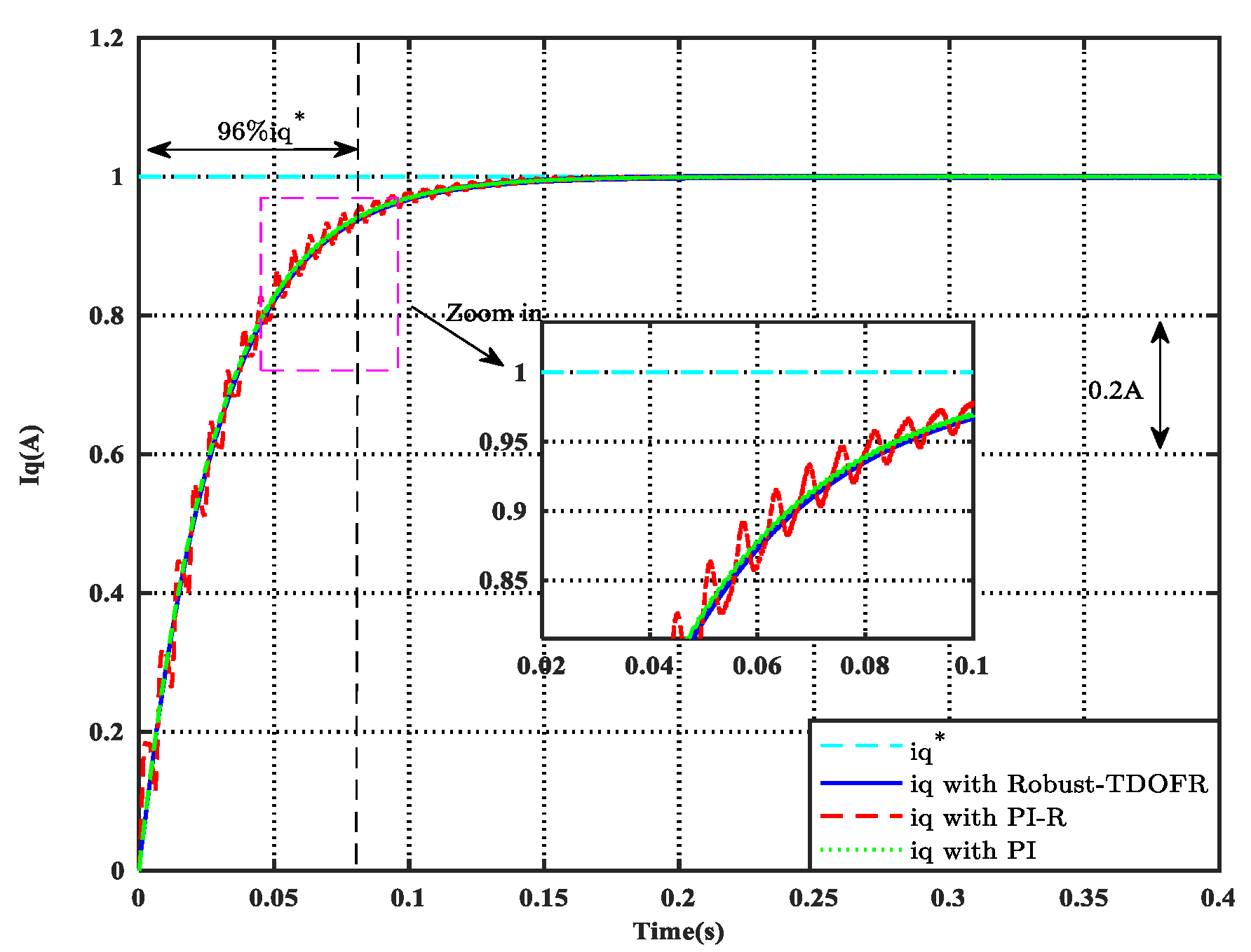
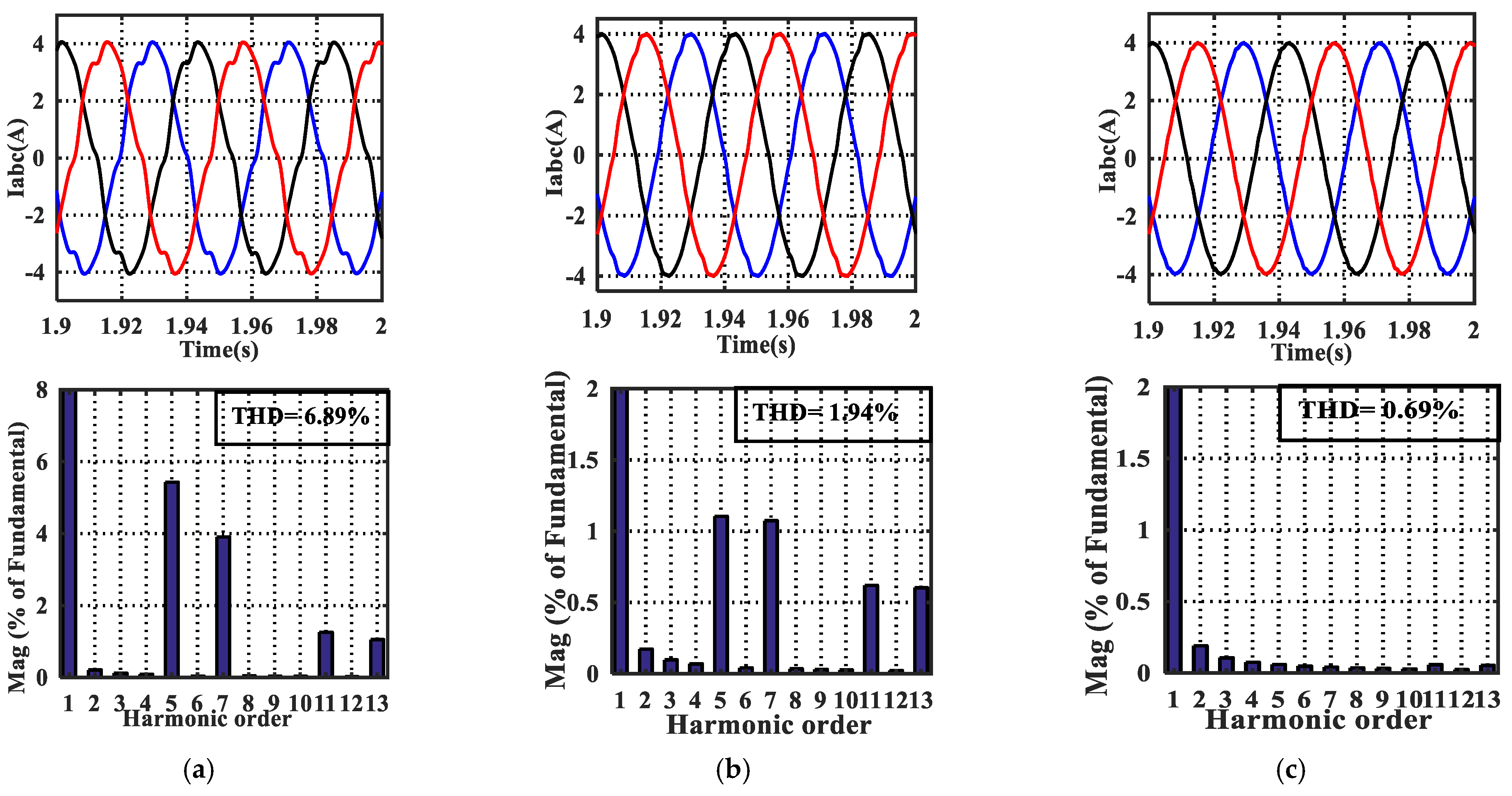
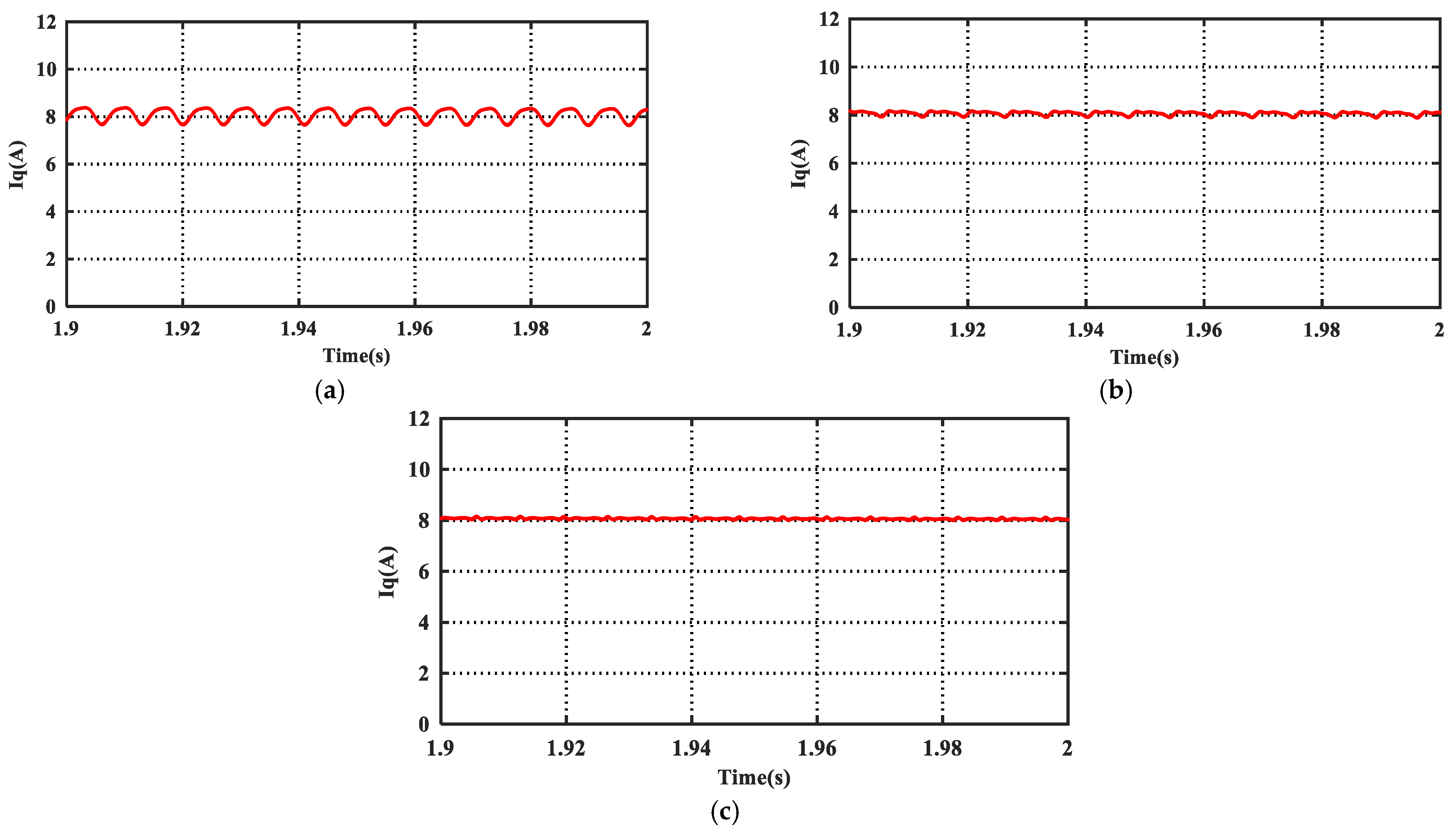
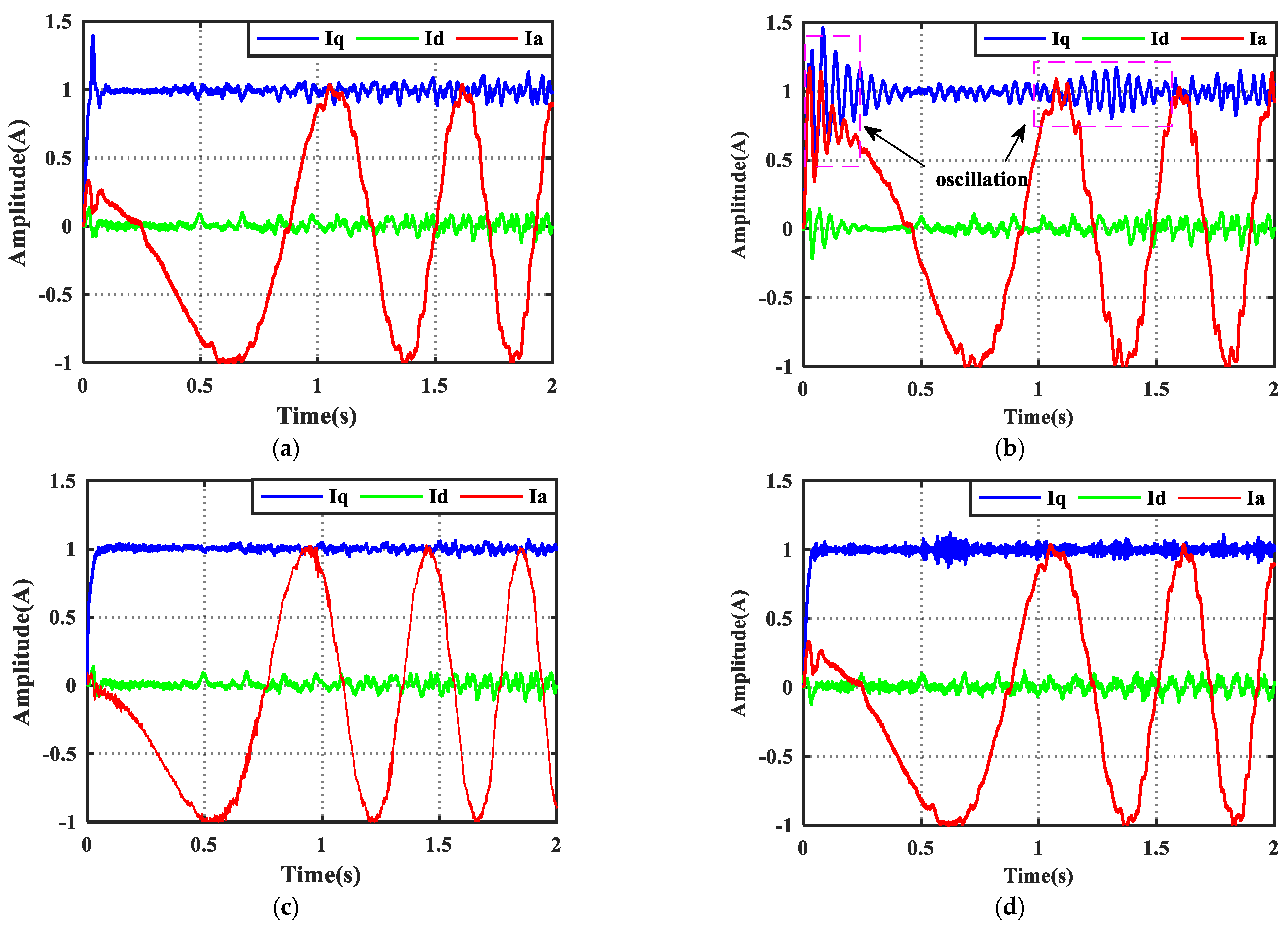
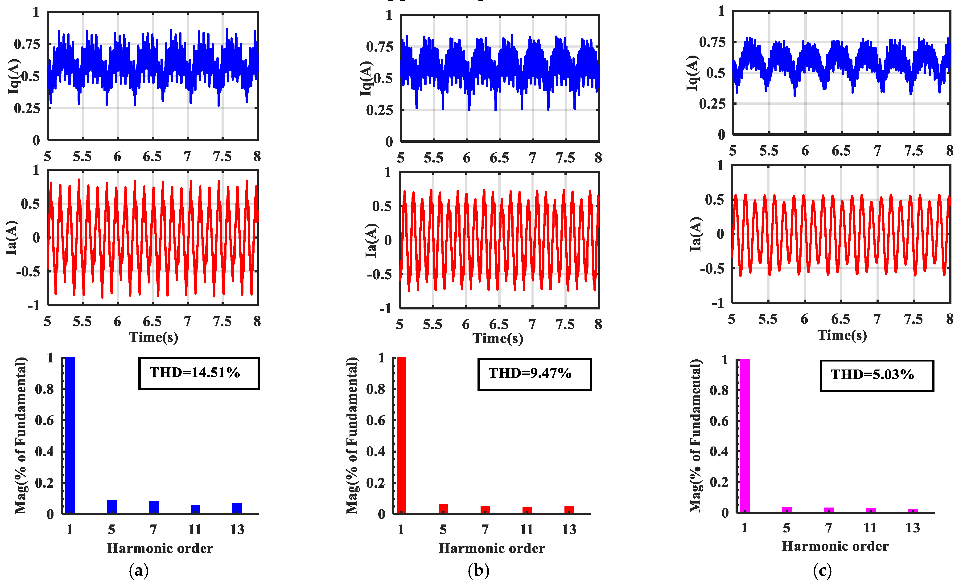
4.1. Simulation Results

The control diagram of PMSM shown in Figure 7 was conducted in MATLAB-SIMULINK to verify the proposed Robust-TDOFR controller. The field orientated control method (FOC) was used to obtain maximum output torque and maintain i d = 0 . The switching frequency and bus voltage of inverter were set as 10 kHz and 380 V, respectively. Note that the control diagram of PMSM constructed in MATLAB was an ideal model, and the dead time effect of inverter and current measure errors were not considered in the modeling. Hence, the current harmonics will not appear in a current loop. To simulate the actual motor drive system, the sixth and twelfth harmonic components are injected in the inverter. The simulation mainly focuses on the dynamic response, current loop robustness and harmonics suppression performances.
(1) Dynamic response evaluation: to highlight the effectiveness of the proposed controller on minimizing the oscillation caused by resonant controller, the PI controller and Robust-TDOFR controller were tuned to make the dynamic response reach the 96% i q r e f within the same time. Then, the dynamic response with PI-R and Robust-TDOFR are compared.
The parameters of PI-R and Robust-TDOFR are presented in Table 2.
Figure 8 shows the dynamics response of PIR and Robust-TDOFR. It can be seen that the oscillation occurs in the transition process when the PIR controller is employed in current loop. The oscillation seriously weakens the dynamic response of control system. Thus, it can be concluded that the PI controller has limited ability to suppress the oscillation caused by resonant controllers. When the proposed Robust-TDOFR is used, the oscillation is effectively eliminated. The negative impact of resonant controllers has been reduced to an extremely low level, which indicates better dynamic response can be obtained.
Figure 9 exhibits the dynamic response of the PI and Robust-TDOFR when parameters of PMSM variation. As can be seen from Figure 9a, a large overshoot occurs in the current loop when the PI controller is used after inductance changes to L = 3 L 0 . The overshoot extends the settling time to reach the steady state. As opposed to the PI controller, the tracking trajectory with Robust-TDOFR showed little changed. The trace trajectory still reached the steady state according to the preset dynamic behavior. Figure 9b demonstrates the dynamic response under the parameter variation of R = 6 R 0 . The trajectory with the PI controller reached the command current without overshoot; nevertheless, a long settling time was required. By contrast, the dynamic response with Robust-TDOFR controller was not affected by the reluctance variation. The simulation results proved that the Robust-TDOFR has strong robustness with respect to parameter mismatch.
(2) Current loop harmonic suppression performance evaluation: To verify the proposed control method, the PI and PIR controllers were selected for comparison. The parameters of PI and PIR are listed in Table 2. The motor ran in the operation of load and no-load under a speed of 1500 /π r/ min. The electrical angular frequency can be calculated by ω h = 150   rad / s . Figure 10a shows the phase current and FFT (fast Fourier transform) analysis with the PI controller. It can be observed that the phase current was distorted by the fifth, seventh, eleventh, and thirteenth harmonic components. The amplitude of fundamental frequency (23.87 Hz) was 3.97 A, and the amplitude of the fifth, seventh, eleventh, and thirteenth harmonics were 0.22 A, 0.16A, 0.049 A and 0.042 A, respectively. The total harmonic distortion (THD) is used to evaluate the quality of the phase current, and is calculated by:
T H D = i = 2 n ( I n I 1 ) 2
where I n and I 1 represent the amplitude of nth harmonics and fundamental frequency, respectively.
According to Equation (42), the THD value with a PI controller is 6.89%, which is relatively large. These harmonic components will weaken the steady state performance, which should be suppressed in high performance drive system.
Figure 10b shows the phase current with a PIR controller; it can be seen that the phase current quality is better, and the magnitudes of the fifth, seventh, eleventh, and thirteenth harmonic components are reduced by 80% (from 0.22 to 0.044 A), 73.75% (from 0.16 to 0.042 A), 50.20% (from 0.049 to 0.0244 A) and 43.33% (from 0.042 to 0.0238 A), respectively. The THD is decreased by 71.84% (from 6.89% to 1.94%). The FFT analysis suggests that the PIR controller can obtain satisfactory harmonics suppression performance to the fifth and seventh harmonics. However, the eleventh and thirteenth harmonic components equivalent to the twelfth in the dq-axis cannot be suppressed effectively.
Figure 10c exhibits the simulation result with the proposed Robust-TDOFR controller. It can be seen that the phase current is further improved, and the fifth, seventh, eleventh, and thirteenth amplitudes are decreased by 98.95% (from to 0.22 to 0.0023 A), 99% (from 0.16 to 0.0016 A), 95.5% (from 0.049 to 0.0022 A) and 95% (from 0.042 to 0.0021 A), respectively, compared with the PI controller. The THD has dropped to a value of 0.69%. The simulation results prove that the proposed controller can effectively suppress the sixth and twelfth harmonics in the dq-axis. The magnitudes of the fifth, seventh, eleventh, and thirteenth harmonics with three control methods under the operation of no load are listed in Table 3.
Figure 11 exhibits the steady-state performance of the q-axis current with three control methods. The ratio of peak-to-peak current to average current is used as an index of the torque ripple evaluation, which can be expressed as:
S R F = S p c / S a c
As can be seen from Figure 11a, the q-axis current fluctuates with sixth and twelfth harmonic components when the PI controller is utilized for current regulation. The SRF of the PI controller reaches a value of 9.12%. By comparing with a PI controller, the SRF with PIR controllers (corresponding to Figure 11b) have decreased to 3.43%. In contrast to PI and PIR controllers, the q-axis SRF value has reduced to a level of 1.56%. Therefore, the effectiveness of the proposed controller is verified.
(3) Harmonics suppression evaluation with a sudden load: Figure 12 shows the current waveform with three control methods under the operation of sudden load, at a load time of 2 s. The signal from 2.5 s to 2.6 is used to analyze the harmonic components. When the PI controller was used, the THD reaches a value of 8.35%, and the amplitude of the fifth, seventh, eleventh, and thirteenth harmonic components were 0.33 A, 0.25 A, 0.092 A and 0.079 A, respectively. Compared with the PI controller, the THD with the PIR controller decreased by 42.5%. Meanwhile, the fifth, seventh, eleventh, and thirteenth harmonic components were reduced by 65.15%, 60.8%, 44.56% and 45.57%, respectively. Figure 12c shows the current and FFT analysis when the Robust-TDOFR controller was utilized in current loop. By comparing with PI controller, the harmonic components are decreased by 83.94% (fifth), 85.6% (seventh), 76.08% (eleventh) and 77.21% (twelfth). Furthermore, the THD has a drop of 50.41%. The simulation results with a sudden load are shown in Table 4.
Figure 13 demonstrates the q-axis current curve with a loading case. It can be observed that the transition process from a no-load to load state with the proposed Robust-TDOFR controller is smoother than with the PI and PIR controllers. Furthermore, the SRF value with the Robust-TDOFR control method (from 3.6 s to 4.0 s) has dropped to 1.58%, while that with PI and PIR controllers are 8.91% and 3.16%, respectively. Hence, it can be concluded that the proposed Robust-TDOFR controller can achieve better dynamic response and smaller torque ripple in the case of load conditions.

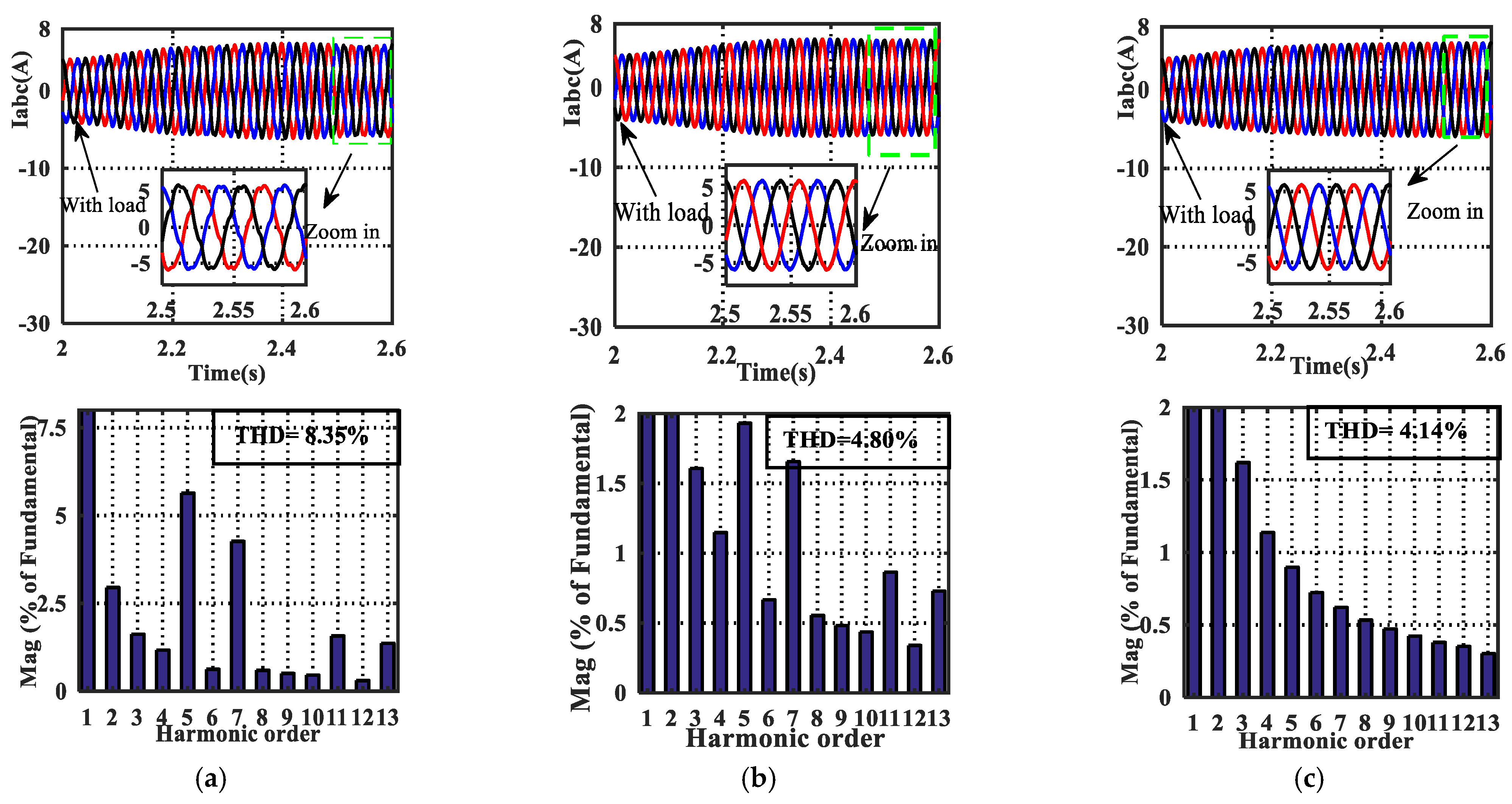
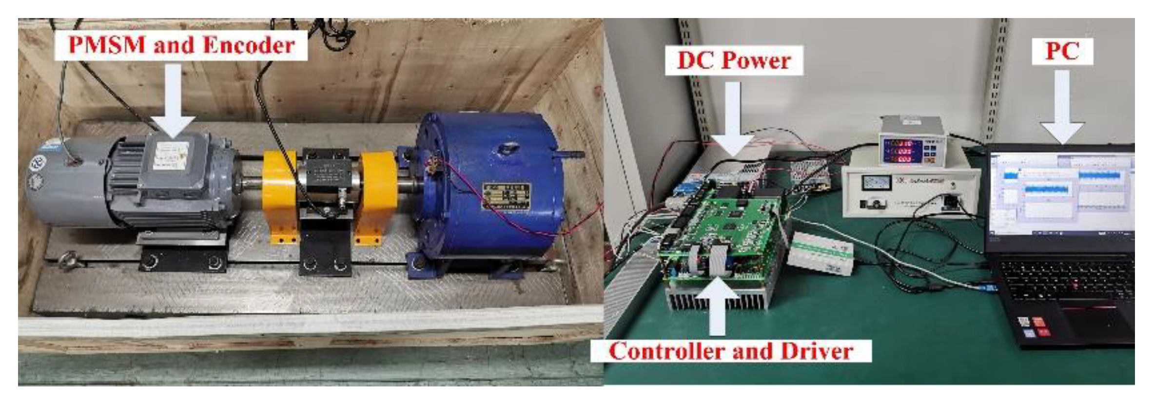
4.2. Experimental Results

In order to verify the effectiveness of our proposed Robust-TDOFR control strategy, the experiment was performed in the test setup shown in Figure 14. The hardware architecture of DSP TMS320F28335 with FPGA-EP3C40F324 was adopted in the servo control system. A diagram of the overall structure of the PMSM is shown in Figure 15. The FPGA (field programmable gate array device) was used for encoder reading and generating IGBT (insulated gate bipolar transistor) control signals, and the DSP was employed to control the motor. The sampling frequencies of the speed and current loops were set as 1 kHz and 10 kHz, respectively.
(1) Current dynamic response: As can be seen from Figure 16a, the dynamic response with a traditional PI controller occurred with a certain overshoot, which resulted in a long settling time. Meanwhile, the oscillation further deteriorated the transition response when a resonant controller was used in the current loop (corresponding to Figure 16b). It is demonstrated from Figure 16c that the proposed controller shows better tracking performance in terms of settling time and overshoot. Figure 16d demonstrates the dynamic response of the proposed controller when parameter mismatch L = 3 L 0 and R = 6 R 0 . It can be seen that the tracking trajectory in such a case shows little change compared with the original dynamic response (corresponding to Figure 16c). The experimental results show that the proposed controller has a strong robust ability to parameter mismatches.
(2) Current loop harmonic suppression performance evaluation without load: Figure 17 shows the phase current and q-axis current when PI, PIR and our method used in current loop. The magnitudes of the fifth, seventh, eleventh, and thirteenth harmonic components with the PI controller were 0.037 A, 0.033 A, 0.023 A and 0.028 A, respectively, and the THD was 14.51%. It can be observed that the current waveform was improved when a PIR controller is used in the current loop. The magnitudes of the harmonic components decreased to 0.018 A, 0.0148 A, 0.012 A and 0.014 A, respectively. Meanwhile, the THD was reduced to 9.47%. As can be observed from Figure 17c, the current quality was further improved when the proposed Robust-TDOFR controller was employed in the current loop. The magnitudes of the harmonic components and THD dropped to 0.0075 A, 0.0072 A, 0.006 A, 0.0052 A and 5.03%, respectively (the experimental results are summarized in Table 5). The experimental results show that the proposed controller can obtain better harmonic suppression performance than PI and PIR controllers.
(3) Harmonic suppression evaluation with sudden load: Figure 18a shows the phase current of I a with the PI controller; it can be observed that the current was distorted by the current harmonics, and the THD reached a value of 18.67%. By comparing Figure 18b with Figure 18a, the quality of phase current was improved, and the THD was reduced to 10.16%. It can be concluded that the PIR controller can suppress the harmonic components to some degree. Figure 18c demonstrates the phase current with the proposed Robust-TDOFR controller, and the THD further decreased to a value of 5.79%. The corresponding q-axis current is shown in Figure 19. These experimental results exhibit that the proposed controller can ensure a better harmonic suppression performance than PI and PIR controllers under the condition of sudden load. Table 6 summarizes the results of the three control methods.

5. Conclusions

This study proposed an improved Robust-TDOF controller with multiple series resonant controllers to suppress the current harmonics and reduce torque ripple. The Robust-TDOF controller was designed to guarantee robust performance to model uncertainty and achieve a satisfactory dynamic response, and the resonant controller with a series connection structure was used to reject the high-frequency unmodeled disturbances. The stability and robust stability conditions derived in this paper were set as two constraints to determine the controller parameters. We also found that the Robust-TDOF controller can eliminate the oscillation caused by the resonant controller. Therefore, a hybrid control method combining Robust-TDOF and series resonant controllers was explored, which can not only realize satisfactory dynamic response, but also ensure strong robustness to parameter mismatch and periodic disturbance. The simulations and experiments were carried out to verify the effectiveness of our method.

Author Contributions

M.H., Y.D. and H.L. designed the proposed control strategy; M.H., Y.D., M.S. and Q.F. conducted the experiments, modeling, and simulations; Y.D. and J.L. helped with writing the paper. All authors have read and agreed to the published version of the manuscript.

Funding

This work was supported in part by the National Natural Science Foundation of China (No. 11603024 and 11973041) and the Youth Innovation Promotion Association, CAS (2019218).

Institutional Review Board Statement

Not applicable.

Informed Consent Statement

Not applicable.

Data Availability Statement

Data is contained within the article.

Conflicts of Interest

The authors declare no conflict of interest.

References

  1. Zhou, X.; Sun, J.; Li, H.; Song, X. High performance three-phase PMSM open-phase fault-tolerant method based on reference frame transformation. IEEE Trans. Ind. Electron. 2019, 66, 7571–7580. [Google Scholar] [CrossRef]
  2. Hang, J.; Zhang, J.; Xia, M.; Ding, S.; Hua, W. Interturn fault diagnosis for model-predictive-controlled-PMSM based on cost function and wavelet transform. IEEE Trans. Power Electron. 2020, 35, 6405–6418. [Google Scholar] [CrossRef]
  3. Yuan, X.; Zhang, S.; Zhang, C. Enhanced robust deadbeat predictive current control for PMSM drives. IEEE Access. 2019, 7, 148218–148230. [Google Scholar] [CrossRef]
  4. Zhang, X.; Sun, L.; Zhao, K.; Sun, L. Nonlinear Speed Control for PMSM System Using Sliding-Mode Control and Disturbance Compensation Techniques. IEEE Trans. Power Electron. 2013, 28, 1358–1365. [Google Scholar] [CrossRef]
  5. Deng, Y.; Wang, J.; Li, H.; Liu, J.; Tian, D. Adaptive sliding mode current control with sliding mode disturbance observer for PMSM drives. ISA Trans. 2019, 88, 113–126. [Google Scholar] [CrossRef]
  6. Zhang, X.; Li, Z. Sliding-mode observer-based mechanical parameter estimation for permanent magnet synchronous motor. IEEE Trans. Power Electron. 2016, 31, 5732–5745. [Google Scholar] [CrossRef]
  7. Liu, M.; Chan, K.W.; Hu, J.; Xu, W.; Rodriguez, J. Model predictive direct speed control with torque oscillation reduction for PMSM drives. IEEE Trans. Ind. Informat. 2019, 15, 4944–4956. [Google Scholar] [CrossRef]
  8. Li, J.; Ren, H.; Zhong, Y. Robust Speed Control of Induction Motor Drives Using First-Order Auto-Disturbance Rejection Controllers. IEEE Trans. Ind. Appl. 2015, 51, 712–720. [Google Scholar] [CrossRef]
  9. Guo, T.; Sun, Z.; Wang, X.; Li, S.; Zhang, K. A simple current-constrained controller for permanent-magnet synchronous motor. IEEE Trans. Ind. Informat. 2019, 15, 1486–1495. [Google Scholar] [CrossRef]
  10. Dai, C.; Guo, T.; Yang, J.; Li, S. A disturbance observer-based current-constrained controller for speed regulation of PMSM systems subject to unmatched disturbances. IEEE Trans. Ind. Electron. 2021, 68, 767–775. [Google Scholar] [CrossRef]
  11. Umeno, T.; Hori, Y. Robust DC servosystem design based on the parametrization of two degrees-of-freedom control systems. In Proceedings of the 15th Annual Conference of IEEE Industrial Electronics Society, Philadelphia, PA, USA, 6–10 November 1989; Volume 2, pp. 313–318. [Google Scholar]
  12. Umeno, T.; Hori, Y. Robust speed control of dc servomotor using modern two degrees-of-freedom controller design. IEEE Trans. Ind. Electron. 1991, 38, 363–368. [Google Scholar] [CrossRef]
  13. Harnefors, L.; Saarakkala, S.E.; Hinkkanen, M. Speed control of electrical drives using classical control methods. IEEE Trans. Ind Appl. 2013, 49, 889–898. [Google Scholar] [CrossRef]
  14. Chuen-Gan, W.; Qiu, L. Robust two degree of freedom regulators for velocity ripple elimination of AC permanent magnet motors. In Proceedings of the 2000 IEEE International Conference on Control Applications, Anchorage, AK, USA, 25–27 September 2000; pp. 156–161. [Google Scholar]
  15. Son, Y.I.; Kim, I.H.; Choi, D.S.; Shim, H. Robust cascade control of electric motor drives using dual reduced-order PI observer. IEEE Trans. Ind. Electron. 2015, 62, 3672–3682. [Google Scholar] [CrossRef]
  16. Xia, C.; Ji, B.; Shi, T.; Yan, Y. Two-degree-of-freedom proportional integral speed control of electrical drives with Kalman-filter-based speed estimation. IET Electr. Power Appl. 2016, 10, 18–24. [Google Scholar] [CrossRef]
  17. Mendoza-Mondragón, F.; Hernández-Guzmán, V.M.; Rodríguez-Reséndiz, J. Robust Speed Control of Permanent Magnet Synchronous Motors Using Two-Degrees-of-Freedom Control. IEEE Trans. Ind. Electron. 2018, 65, 6099–6108. [Google Scholar] [CrossRef]
  18. Fei, Q.; Deng, Y.; Li, H.; Liu, J.; Shao, M. Speed ripple minimization of permanent magnet synchronous motor based on model predictive and iterative learning controls. IEEE Access. 2019, 7, 31791–31800. [Google Scholar] [CrossRef]
  19. Liu, J.; Li, H.; Deng, Y. Torque ripple minimization of PMSM based on robust ILC via adaptive sliding mode control. IEEE Trans. Power Electron. 2018, 33, 3655–3671. [Google Scholar] [CrossRef]
  20. Zhu, Q.; Song, F.; Xu, J.; Liu, Y. An Internal Model Based Iterative Learning Control for Wafer Scanner Systems. IEEE/ASME Trans. Mechatron. 2019, 24, 2073–2084. [Google Scholar] [CrossRef]
  21. Wang, L.; Freeman, C.T.; Chai, S.; Rogers, E. Predictive-repetitive control with constraints: From design to implementation. J. Process Control. 2013, 23, 956–967. [Google Scholar] [CrossRef]
  22. Feng, G.; Lai, C.; Kar, N.C. Speed harmonic based decoupled torque ripple minimization control for permanent magnet synchronous machine with minimized loss. IEEE Trans. Energy Convers. 2020, 35, 1796–1805. [Google Scholar] [CrossRef]
  23. Seifi, K.; Moallem, M. An adaptive PR Controller for synchronizing grid-connected inverters. IEEE Trans. Ind. Electron. 2019, 66, 2034–2043. [Google Scholar] [CrossRef]
  24. Pang, B.; Nian, H.; Wu, C.; Cheng, P. Stator harmonic current suppression for DFIG system considering integer harmonics and inter harmonics. IEEE Trans. Ind. Electron. 2019, 66, 7001–7011. [Google Scholar] [CrossRef]
  25. Xia, C.; Ji, B.; Yan, Y. Smooth speed control for low-speed high-torque permanent-magnet synchronous motor using proportional–integral–resonant controller. IEEE Trans. Ind. Electron. 2015, 62, 2123–2134. [Google Scholar] [CrossRef]
  26. Wang, Z.; Zhao, J.; Wang, L.; Li, M.; Hu, Y. Combined vector resonant and active disturbance rejection control for PMSLM current harmonic suppression. IEEE Trans. Ind. Informat. 2020, 16, 5691–5702. [Google Scholar] [CrossRef]
  27. Chen, Y.Q.; Petras, I.; Xue, D. Fractional order control—A tutorial. In Proceedings of the 2009 American Control Conference (ACC), St. Louis, MO, USA, 10–12 July 2009; pp. 1397–1411. [Google Scholar]
  28. Malti, R.; Moreau, X.; Khemane, F.; Oustaloup, A. Stability and resonance conditions of elementary fractional transfer functions. Automatica 2011, 47, 2462–2467. [Google Scholar] [CrossRef]
  29. Sami, I.; Ullah, S.; Basit, A.; Ullah, N.; Ro, J.-S. Integral super twisting sliding mode based sensorless predictive torque control of induction motor. IEEE Access. 2020, 8, 186740–186755. [Google Scholar] [CrossRef]
  30. Sami, I.; Ullah, S.; Ullah, N.; Ro, J.-S. Sensorless fractional order composite sliding mode control design for wind generation system. ISA Trans. 2020. [Google Scholar] [CrossRef]
  31. Sami, I.; Ullah, S.; Ali, Z.; Ullah, N.; Ro, J.-S. A super twisting fractional order terminal sliding mode control for DFIG-Based wind energy conversion system. Energies 2020, 13, 2158. [Google Scholar] [CrossRef]
  32. Araki, M.; Taguchi, H. Two-degree-of-freedom PID controllers. Int. J. Control Autom. Syst. 2003, 1, 401–411. [Google Scholar]
  33. Teodorescu, R.; Blaabjerg, F.; Liserre, M.; Loh, P.C. Proportional resonant controllers and filters for grid-connected voltage-source converters. IEEE Proc. Electric Power Appl. 2006, 153, 750–762. [Google Scholar] [CrossRef] [Green Version]
  34. Hao, Y.; Zhuo, F.; Wang, F. Analysis about overshoot peaks appearing in the current loop with resonant controller. IEEE J. Emerg. Sel. Topics Power Electron. 2016, 4, 26–36. [Google Scholar]
  35. Li, D.; Iwaji, Y.; Notohara, Y.; Kishita, K. Harmonic Current Cancellation Method for PMSM Drive System using Resonant Controllers. In Proceedings of the 2018 International Power Electronics Conference (IPEC-Niigata 2018—ECCE Asia), Niigata, Japan, 20–24 May 2018; pp. 1301–1307. [Google Scholar]
  36. Li, C.-X.; Gu, G.-Y.; Yang, M.-J.; Zhu, L.-M. High-speed tracking of a nanopositioning stage using modified repetitive control. IEEE Trans. Autom. Sci. Eng. 2017, 14, 1467–1477. [Google Scholar] [CrossRef]
  37. Holmes, D.G.; Lipo, T.A.; McGrath, B.P.; Kong, W.Y. Optimized design of stationary frame three phase AC current regulators. IEEE Trans. Power Electron. 2009, 24, 2417–2426. [Google Scholar] [CrossRef]
  38. Elkayam, M.; Kolesnik, S.; Kuperman, A. Guidelines to classical frequency-domain disturbance observer redesign for enhanced rejection of periodic uncertainties and disturbances. IEEE Trans. Power Electron. 2019, 34, 3986–3995. [Google Scholar] [CrossRef]
Figure 1. Diagram of the robust two degrees-of-freedom (Robust−TDOF) controller.
Energies 14 01015 g001
Figure 2. Control diagram of Robust−TDOF cascaded resonant controller.
Energies 14 01015 g002
Figure 3. Bode diagram of 1 + H ( s ) : (a) increasing k with constant ξ = 10 rad/s and α = 0.1 , (b) increasing ξ with constant k = 10 and α = 0.1 , and (c) increasing α with constant k = 5 and ξ = 10 rad/s.
Energies 14 01015 g003
Figure 4. Bode diagram of Φ ( s ) and H ( s ) .
Energies 14 01015 g004
Figure 5. Bode diagram of H m a x ( s ) .
Energies 14 01015 g005
Figure 6. Bode diagram performance comparison of the traditional Robust-TDOF and Robust-TDOFR controller: (a) loop gain function and (b) sensitive function.
Energies 14 01015 g006
Figure 7. Structure diagram of the proposed Robust-TDOFR controller.
Energies 14 01015 g007
Figure 8. Step response comparison results of Robust-TDOFR and PIR.
Energies 14 01015 g008
Figure 9. (a) Step response comparison results of Robust-TDOFR and PIR when L = 3 L 0 , R = R 0 and (b) step response comparison results of Robust-TDOFR and PI when L = L 0 , R = 6 R 0 .
Energies 14 01015 g009
Figure 10. Simulation results of phase current and FFT analysis without load: (a) with a PI controller, (b) with a PIR controller and (c) with the Robust-TDOFR controller.
Energies 14 01015 g010
Figure 11. Simulation results of the q-axis current in the steady-state without load: (a) with a PI controller, (b) with a PIR controller and (c) with a Robust-TDOFR controller.
Energies 14 01015 g011
Figure 12. Simulation results of phase current and FFT analysis with load: (a) with a PI controller, (b) with a PIR controller and (c) with a Robust-TDOFR controller.
Energies 14 01015 g012
Figure 13. Simulation results of q-axis current during the load operation: (a) with a PI controller, (b) with a PIR controller and (c) with a Robust-TDOFR controller.
Energies 14 01015 g013
Figure 14. Photograph of the experimental platform.
Energies 14 01015 g014
Figure 15. Structural diagram of the PMSM servo system.
Energies 14 01015 g015
Figure 16. Step response comparison results: (a) with a PI controller, (b) With a PIR controller, (c) with the proposed Robust-TDOFR controller ( L = L 0 , R = R 0 ) and (d) with the proposed Robust-TDOFR controller ( L = 3 L 0 , R = 6 R 0 ).
Energies 14 01015 g016
Figure 17. Phase current and FFT analysis results: (a) with a PI controller, (b) with a PIR controller and (c) with a Robust-TDOFR controller.
Energies 14 01015 g017
Figure 18. Simulation results of phase current and FFT analysis with load: (a) with a PI controller, (b) with a PIR controller and (c) with a Robust-TDOFR controller.
Energies 14 01015 g018
Figure 19. Experimental results of q-axis current during the load operation: (a) with a PI controller, (b) with a PIR controller and (c) with a Robust-TDOFR controller.
Energies 14 01015 g019
Table 1. Parameters of the permanent magnet synchronous motor (PMSM).
SymbolQuantityValue
Ld–q frame inductance0.0085 H
RArmature resistance0.569 Ω
PNumber of pole pairs3
FFlux linkage0.00175 Wb
JInertia0.0012 kg·m2
Table 2. Parameters of the FOVR-Robust-IMC.
Robust-TDOFR λ τ L 0 R 0 k ξ α
0.00060.0280.00850.56920150.3
PI-R k p k i k 6 k 12 ω c
0.320202015
Table 3. Simulation results under the operation of no-load.
Harmonic OrderFifthSeventhEleventhThirteenthTHD (%)
PIAmplitude
(A)
0.220.0020.0490.0426.89
PIR0.0440.0420.02440.02381.94
Robust-TDOFR0.00230.00160.00220.00210.69
Table 4. Simulation results under the operation of load.
Harmonic OrderFifthSeventhEleventhThirteenthTHD (%)
PIAmplitude
(A)
0.330.250.0920.0798.35
PIR0.1150.0980.0510.02384.80
Robust-TDOFR0.0530.0370.0220.0174.14
Table 5. Experimental results under the operation of load.
Harmonic OrderFifthSeventhEleventhThirteenthTHD (%)
PIAmplitude
(A)
0.0370.0330.0230.02814. 51
PIR0.0180.01480.0120.0149.47
Robust-TDOFR0.00750.00720.0060.00525.03
Table 6. Experimental results under the operation of sudden load.
Harmonic OrderFifthSeventhEleventhThirteenthTHD (%)
PIAmplitude
(A)
0.0480.0420.0330.03118. 67
PIR0.0200.01520.01250.015510.16
Robust-TDOFR0.00860.008170.00690.006185.79
Publisher’s Note: MDPI stays neutral with regard to jurisdictional claims in published maps and institutional affiliations.

