Article

A Novel Iron Chloride Red-Ox Concentration Flow Cell Battery (ICFB) Concept; Power and Electrode Optimization

by
Robert Bock
1,
Björn Kleinsteinberg
2,3,
Bjørn Selnes-Volseth
1 and
Odne Stokke Burheim
1,*
1
Department of Energy and Process Engineering, Norwegian University of Science and Technology, NO-7491 Trondheim, Norway
2
Electrochemical Energy Conversion and Storage Systems Group, Institute for Power Electronics and Electrical Drives (ISEA), RWTH Aachen University, 52062 Aachen, Germany
3
Helmholtz Institute Münster (HI MS), IEK-12, Forschungszentrum Juelich, Corrensstrasse 46, 48149 Münster, Germany
*
Author to whom correspondence should be addressed.
Energies 2021, 14(4), 1109; https://doi.org/10.3390/en14041109
Submission received: 10 December 2020 / Revised: 9 February 2021 / Accepted: 11 February 2021 / Published: 19 February 2021
(This article belongs to the Special Issue Advanced Technology to Improve Energy Efficiency and Storage)

Abstract

:
For renewable energies to succeed in replacing fossil fuels, large-scale and affordable solutions are needed for short and long-term energy storage. A potentially inexpensive approach of storing large amounts of energy is through the use of a concentration flow cell that is based on cheap and abundant materials. Here, we propose to use aqueous iron chloride as a reacting solvent on carbon electrodes. We suggest to use it in a red-ox concentration flow cell with two compartments separated by a hydrocarbon-based membrane. In both compartments the red-ox couple of iron II and III reacts, oxidation at the anode and reduction at the cathode. When charging, a concentration difference between the two species grows. When discharging, this concentration difference between iron II and iron III is used to drive the reaction. In this respect it is a concentration driven flow cell redox battery using iron chloride in both solutions. Here, we investigate material combinations, power, and concentration relations.

1. Introduction

As essential as banking is in a monetary economy, energy storage is in a renewable energy economy. A fossil-based energy economy benefits from liquid and gaseous fuels being compatible with bunkering. As particularly photovoltaics made from silica rocks, and wind power turbines made from other abundant materials are continuously falling in price, even below coal and natural gas power plants, their energy output, electricity, is not easily storable. Therefore, vast new energy storage systems are needed. These systems will differ depending on what they are intended for. Transportation will need systems that are based on high specific power and energy, and low volumetric footprints while stationary systems will rely on materials that are cheap and efficient. Cheap in this context means that systems that can use omnipresent materials stand a good chance of becoming important systems. Concentration redox flow cells like the one suggested here, are based on iron oxide ores in an aqueous chloride solution, hydrocarbon-based membranes, and graphite materials [1,2,3].

1.1. Redox Cells vs. Concentration Cells

Currently two types of flow cells are discussed in the literature; concentration cells and redox cells. A redox cell consists of two different solutions stored in separate tanks which are pumped through a reactor whenever energy is needed [4]. Each solution contains a soluble transition metal salt, where the metal has the property of being dissolved in different oxidation states [1]. Nickel, copper, cobalt, iron and many other transition metal salts have this ability [5,6,7,8]. In many redox flow batteries one solution contains one metal and the other solution another metal, like, e.g., Nickel (II/III) in one and Chromium (IV/III) in the other. Typically, both solutions are stabilized by a low pH (−1 to 2) and in the absence of oxygen [2]. Thus, it is the difference in standard reversible potential that is the main driving force. These systems then have massive tanks containing the reactive solutions (and thus the energy capacity of the systems) with adapted reactors sided (for the power capacity of the system). Thus, these systems are very flexible to scale in terms of power and energy capacity needs [4].
A challenge of systems with two different metals is the inevitable crossover of the metals between the two solutions. Eventually, they must be cleaned to restore the original quality. To overcome this challenge, the vanadium redox flow cell battery was introduced [9,10]. Vanadium has the ability to sustain four different distinct oxidation numbers; I, II, III, and IV. By having the redox couple between I and II in one solution and III and IV in the other one, one can obtain a good standard redox potential of around 1.3 V between the two compartments [9]. If some vanadium crosses over, it will be reduced or oxidized into the appropriate oxidation state [11]. Several measures have been taken in order to improve the efficiency of the vanadium redox flow battery, like membrane optimization [12], also by thickness reduction [13], electrode fiber modification [14], and electrolyte optimization [2]. A remaining challenge is that vanadium is an environmentally unfriendly and pollutive material [15]. Therefore its ascendancy is deemed to have an intermediate character within the segment of flow cell energy storage systems.
Concentration cells are best defined by electrodialysis (ED) and reverse ED (RED). In such a system two saline solutions (e.g., NaCl) are fed into a stack of alternated cation and anion exchange membranes (AEM and CEM) while a current is applied to accumulate the salt in every second compartment and the remaining water in the other compartments [16,17,18,19]. By appropriate manifolding, a tank of brine and dilute is established. When the energy is needed, the two solutions are mixed during the reversed process. The challenge of this process is that it requires immense amounts (square kilometers) of membranes [20].
Here, we propose a hybrid solution between the benefits of having one component, a single membrane, and omnipresent raw materials. Several approaches to such an all-iron flow battery have been proposed, which rely on producing metallic iron at the anode, thus abolishing the independence of reactor size and storage capacity [21,22]
We propose to, during discharge, feed the anode with a solution with a very high concentration ratio of Fe(II)/Fe(III) and the cathode compartment with a very high ratio of Fe(III)/(II). In this way, crossover is not a problem and less membrane area than for RED/ED is needed. Additionally, the materials are environmentally friendly and fairly abundant. On a long term basis, membrane interaction and iron stability has to be addressed, but this challenge can be overcome by utilizing sorbitol, ascorbic acid or similar low molecular weight organic acids that are known to stabilize iron in aqueous solutions [23].

1.2. Problem Formulation

In this study we will show the performance and prove the concept of an Iron chloride concentration cell redox flow battery with water based electrolyte. Produced power related to the state of charge and the shape of the graphite electrodes is being investigated and discussed. The open circuit potential of the cell is studied using a potentiostat. We started this investigation to establish future routes for developing a pathway for this concept to become a technological solution.

2. Theory

2.1. Cell Description, at Discharge

The electrochemical cell is a concentration cell with two compartments separated by an anion exchange membrane (AEM) with each compartment containing three components in addition to water:
Anode | FeCl ( 2 , aq . ) An , FeCl ( 3 , aq . ) An , NaCl ( aq . ) An | | AEM FeCl ( 2 , aq . ) Cath , FeCl ( 3 , aq . ) Cath , NaCl ( aq . ) Cath | Cathode
In the case described here, both the cathode and anode material are carbon or carbon-based. The sodium chloride has a main role in supplying ionic conductivity and transport of anions through the membrane and in the electrolyte, and thus increase energy efficiency. At the electrodes Iron(II) and Iron(III) are reduced and oxidized on the cathode and anode correspondingly. The reduction reaction at standard conditions is given in Equation (1) along with its standard reduction potential.
FeCl 3 , diss + e FeCl 2 , diss + Cl diss , E 0 = 0.77 V
During discharge, the direction in Equation (1) is right to left on the anode side, while it is left to right on the cathode, as illustrated in Figure 1.
As illustrated, the concentration of FeCl 2 and FeCl 3 will change during charging/ discharging. This will be reflected on both electrodes. That means, the concentration of FeCl 2 at the anode and FeCl 3 at the cathode will change equally, as do FeCl 2 at the cathode and FeCl 3 at the anode, they are interlocked.

Reversible Reduction Potential

The reversible potential of Equation (1) requires the concentration of the redox species (Fe diss 2 + and Fe diss 3 + ) to be the same in the electrolyte where the half-cell reaction takes place, i.e., their ratio to be unity (not necessarily being 1M each). As soon as the two concentrations differ from each other the reversible reduction potential will deviate from the standard one;
E REV = E 0 R T F ln a FeCl 2 a Cl a FeCl 3
R is the ideal gas constant, T the temperature, F the Faraday constant and a the activity of the components and species. The activity of a dissolved salt can be described as the product of the activity of each of the dissolved species, which in this case are iron (2 + and 3 + ) and chloride. Thus Equation (2) can be written as
E REV = E 0 R T F ln a Fe 2 + a Cl 2 a Cl a Fe 3 + a Cl 3
The activity of a species can be written as the product of the species concentration ( c i ) and the salt mean molar activity coefficient ( γ ¯ ± ). Because the system considered here is such that the concentration of chlorides does not change, they will cancel each other out, so that Equation (3) becomes
E REV = E 0 R T F ln γ ¯ ± , FeCl 2 4 c Fe 2 + c Cl 3 γ ¯ ± , FeCl 3 4 c Fe 3 + c Cl 3 = E 0 R T F ln γ ¯ ± , FeCl 2 4 c Fe 2 + γ ¯ ± , FeCl 3 4 c Fe 3 +
This can in turn be written into
E REV = E 0 R T F ln c FeCl 2 c FeCl 3 R T F ln β i 4
where β i = γ ¯ ± , FeCl 2 γ ¯ ± , FeCl 3 . Because we compare a ratio of two activity coefficients, the concentration of sodium chloride is always constant, and the contribution to the iron chloride mean molar activity coefficients is the same factor in both the nominator and denominator, we can use this simplification (of β ). When comparing the last and second last terms in Equation (5), we can see that they depend differently with the iron (II) and iron(III) concentration ratio. As the ratio of these grow extreme (several orders of magnitude) and one compares the reversible potential to ideal solution, one can then expect a fourth (or simplified to second order) deviation. That is, the beta factor will appear as a quadratic function of the logarithmic concentration ratio of iron (II) and iron(III) chlorides.

2.2. Membrane Potential

So far we have only described the half cell potential. The idea behind this study is that as the relative content of iron(III) increases in one solution and decreases in the other solution, the two half cell potentials given by the concentration and activity coefficient terms give rise to a cell potential;
E cell REV = E anode REV E cathode REV = R T F ln c FeCl 2 , an c FeCl 3 , an 4 R T F ln β an + R T F ln c FeCl 2 , ca c FeCl 3 , ca + 4 R T F ln β ca
E cell REV = R T F ln c FeCl 2 , ca c FeCl 3 , ca c FeCl 3 , an c FeCl 2 , an β ca β an 4
Moreover, because of the symmetry of the system one can expect the activity coefficients in the two chambers to deviate symmetrically so that β ca = β an 1 = β .
Because of the co-transport of water and the possible lack of selectivity towards cations, the actual (open cell) potential, E OCP , will be lower than the reversible potential of the cell, E cell REV . Irrespective of the physical chemical reasons behind this potential drop across the membrane, the ratio between the open cell and the reversible potential is traditionally termed the apparent perm-selectivity, α , so that Equation (6) leads to
E OCP = α R T F ln c FeCl 2 , ca c FeCl 3 , ca c FeCl 3 , an c FeCl 2 , an β 8 .
Under the given circumstances (constant chloride concentrations), the apparent perm-selectivity α , can be expected to only change with temperature while the activity coefficient deviation, β can be expected to change with the state of charge, or the ratio of iron(II) and iron(III) in the different solutions. Because of the power of 8, the behavior with state of charge will appear second order polynomial and symmetric around zero state of charge [24,25,26].

2.3. Power of the Battery

The power of a battery depends on the state of charge of the battery and on the mode, charging or discharging. It usually follows a quadratic function. The power P of a battery is defined in Equation (8).
P = E OCP · j R inner · j 2
E OCP is the open circuit potential, R inner is the inner resistance and j is the current density. A derivation of Equation (8) with respect to j leads to an expression for the current density at maximum power:
P j = E OCP 2 · R inner · j P max = 0
j P max = E OCP 2 · R inner .
To check the consistency of the obtained current density for maximum power j P max , it needs to be compared to the limiting current density j lim :
j P max j lim 1
Different electrode shapes result in differing performances of the cell. The electrode shapes affect the surface area where the reactions take place, the time the electrolyte spends inside the cell, and the pressure drop. The focus in this study is on estimating the potential power of the cell. By testing different electrode configurations, we demonstrate the concept and cycling possibility, and investigate how the potential changes with the state of charge (ratio of iron II and III).

3. Experimental

3.1. Measurement Setup

Potentiostatic measurements were undertaken to determine the open circuit potential. A small flow cell was set up (10 mm × 10 mm active area) and supplied with electrolytes. The electrolytes were circulated with a peristaltic pump (Watson Marlow 400DM2) at a volumetric flow rate of 3 mL/min. The electrochemical reaction takes place in both reaction chambers. A sketch of the battery setup is shown in Figure 2.
The electrolyte is pumped through this cell from the bottom to the top to prevent gas inclusion. The potentiostat used for the measurements (Gamry Interface 5000E) was connected to the cell via two plug holes, as seen in Figure 2b. The respective electrolytes were prepared in a bottle flask by adding deionized water to the required amount of additives until the solution reaches a volume of 100 mL.

3.2. Electrodes

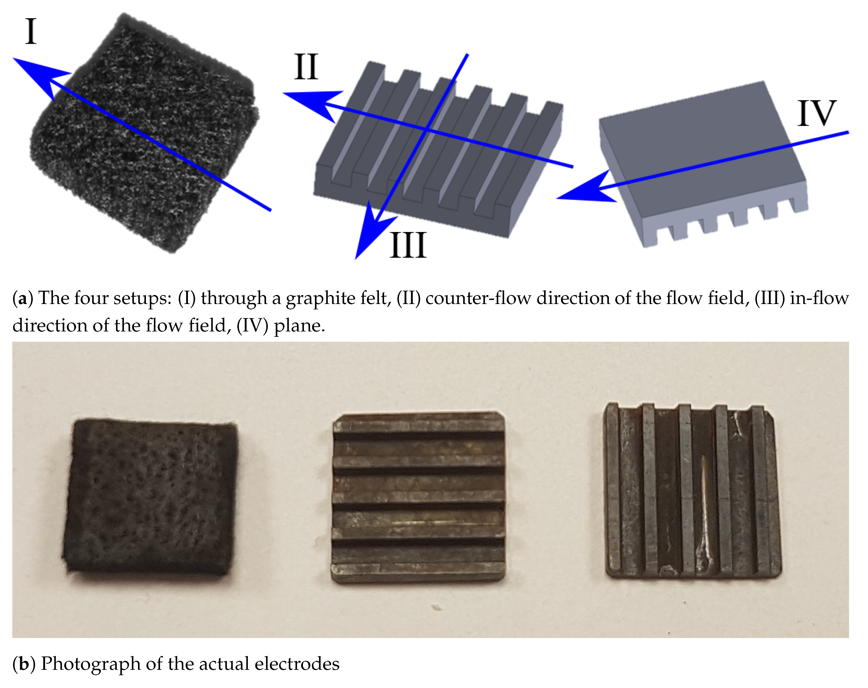
Inside the reaction chambers different graphite electrodes are used, as shown in Figure 3. A plane geometry was tested in comparison to a solid carbon composite flow field geometry with the flow field ribs (1 mm wide, 1 mm high) and channels (1.5 mm wide) parallel as well as transverse to the flow direction of the electrolyte. In addition, a graphite felt (Sigratherm GFD, 4.6 mm thick) was used to maximize the surface area, shown to have very positive effects on power density for vanadium flow cells by Aaron et al. [27].

3.3. Ion Exchange Membrane

The membrane used for this experiment was a FuMA-Tech Fumasep FAP-1 anion exchange membrane. It is reported by the manufacturer to have a permselectivity of 0.9. It was chosen because it was readily available in our lab and shown to be highly mechanically stable.

3.4. Measurement Technique

The measurements were performed with electrolytes of different concentrations of FeCl 2 (Iron(II)chloride tetrahydrate, EMSURE®for analysis, Supelco®), FeCl 3 (Iron(III) chloride, anhydrous, GPR RECTAPUR®) and NaCl (Sodium chloride ≥98%, VWR Chemicals). The applied concentrations are shown in Table 1 with their calculated states of charge (SOC).
The electrodes were supplied with two different, inverse concentration ratios of iron chloride (II/III) (thus with the same SOC). For the open circuit potential measurements, OCP was allowed to settle for an initial period of at least 30 s and was then measured for 300 s.
To obtain the polarization curves, linear sweep voltammetry was used. The maximum current was set to 10,000 A m 2 and the voltage was cycled from 0 to 770 mV with a scan rate of 1 mV s 1 . The conditioning time before every measurement was 15 s followed by a delay of 120 s for the system to equilibrate again.
For the cycling measurements the maximum absolute current was set to 1 mA. For charging, the maximum voltage was set to 770 mV and the cell was charged until the charging current dropped below 0.75 mA or 4 h had passed. For discharging, the minimum voltage was set to 120 mV and the cell was discharged until the cell voltage dropped below that or until 4 h had passed.

4. Results and Discussion

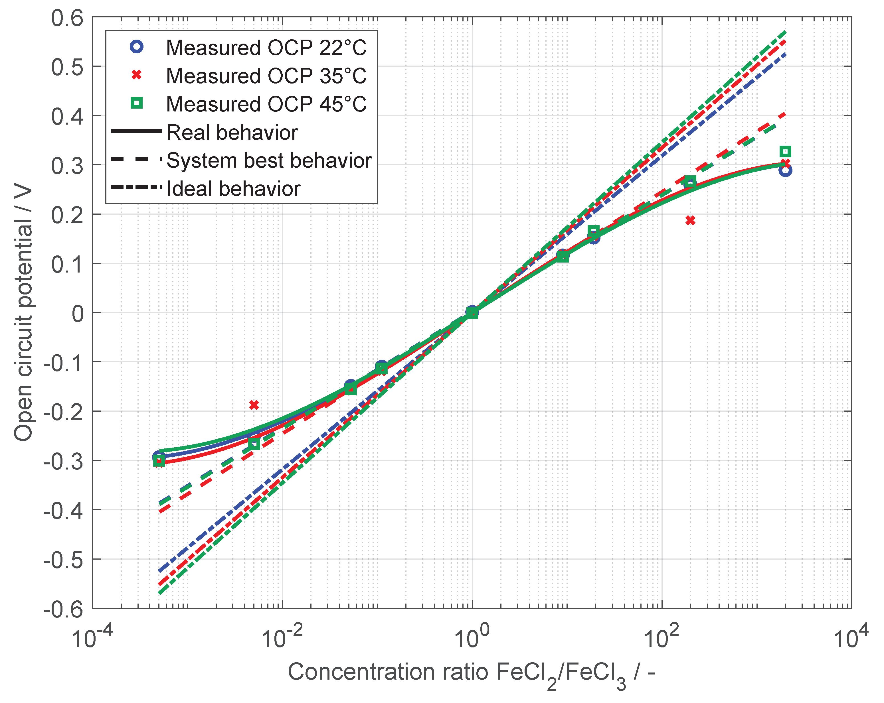
In Figure 4 the measured open circuit potential versus the concentration ratio of FeCl 2 / FeCl 3 is shown at different temperatures.
A concentration ratio of 1 means a fully discharged cell, with the concentration ratio increasing and decreasing during charging in the anolyte and catholyte, respectively. To determine the performance of the cell, open circuit potential (OCP) measurements were done with different electrodes and different premixed FeCl 2 /FeCl 3 concentration ratios. The measured OCPs are shown for the felt electrodes in Figure 4 with different markers for three different system temperatures, 22 °C, 35 °C and 45 °C. The dash-dotted lines show the ideal behavior of such a cell based on the concentration gradient without losses. The dashed lines show the OCP for the best behavior of this system, with losses attributed to the change in activity coefficient ratio expressed by β . They follow the slope of a fit at a concentration ratio of 1. The solid lines show the modification explained in Equation (1) ( β ca = β an 1 = β ) with a fit to the measured OCPs for this range of concentrations. These lines include the losses due to the apparent perm-selectivity and describe the real behaviour of the cell best. The OCPs for the remaining electrode designs did not deviate from the shown ones for felt electrodes and were thus omitted for better visibility.
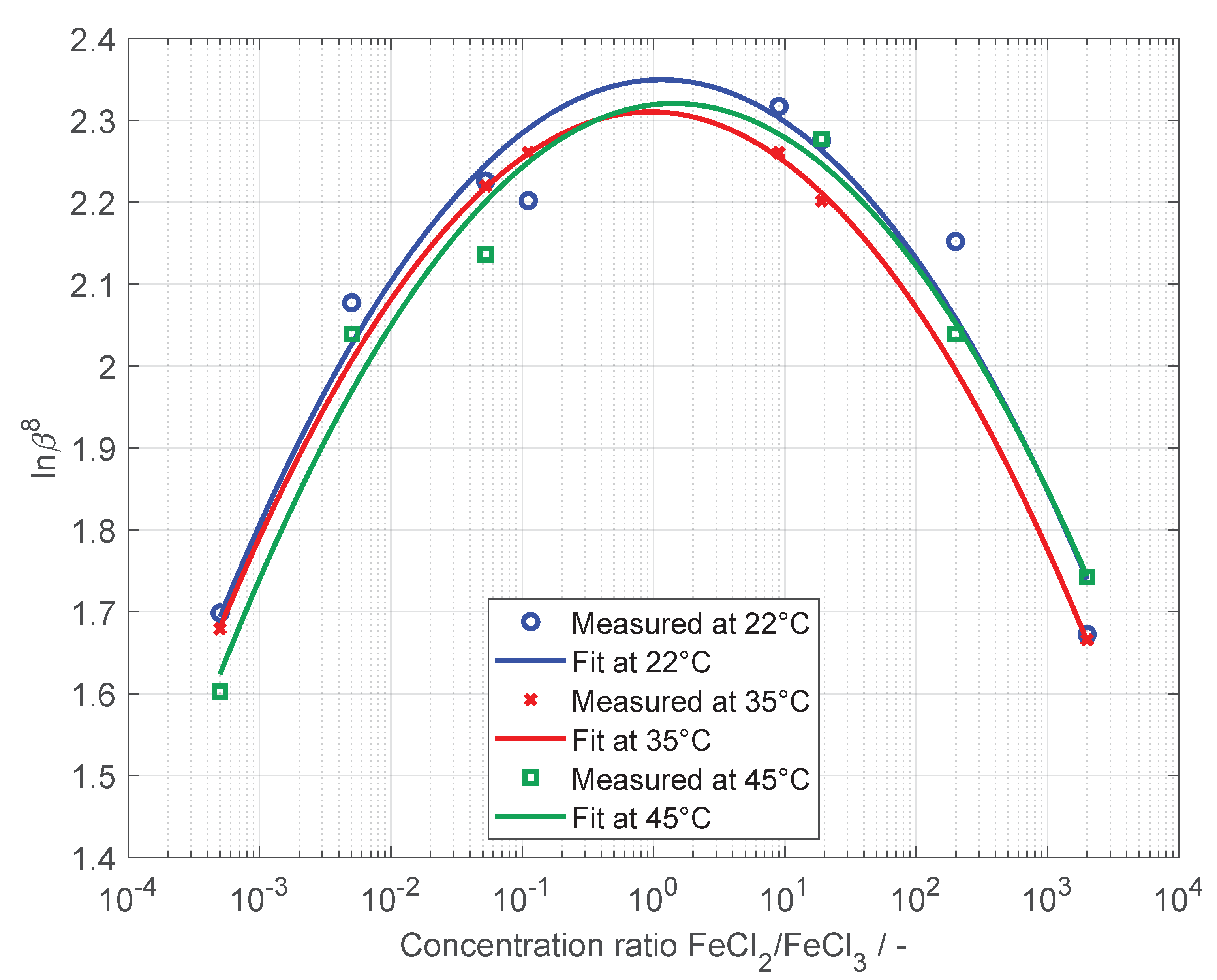
The values obtained for β were calculated using Equation (7), using the measured OCPs, a permselectivity of 0.9 for the membrane and the premixed concentration ratios used during the experiment. The results are plotted in Figure 5 as ln( β 8 ) against the concentration ratio of FeCl 2 /FeCl 3 . They follow a quadratic behaviour around the concentration ratio of 1. The open circuit potentials at an FeCl 2 /FeCl 3 concentration ratio of 0.005 and 0.995 for 35 °C were identified as outliers and excluded from this figure and the calculations of the beta fit curves. As β describes the relation of the activity coefficients of FeCl 2 and FeCl 3 , Figure 5 shows that their ratio is not subject to significant change, keeping in mind that the figure spans seven dimensions of FeCl 2 to FeCl 3 concentration ratio. Measured values for β range from 1.6 to 2.4. It is also clear that a change in temperature does not have a significant effect on how β changes with concentration.
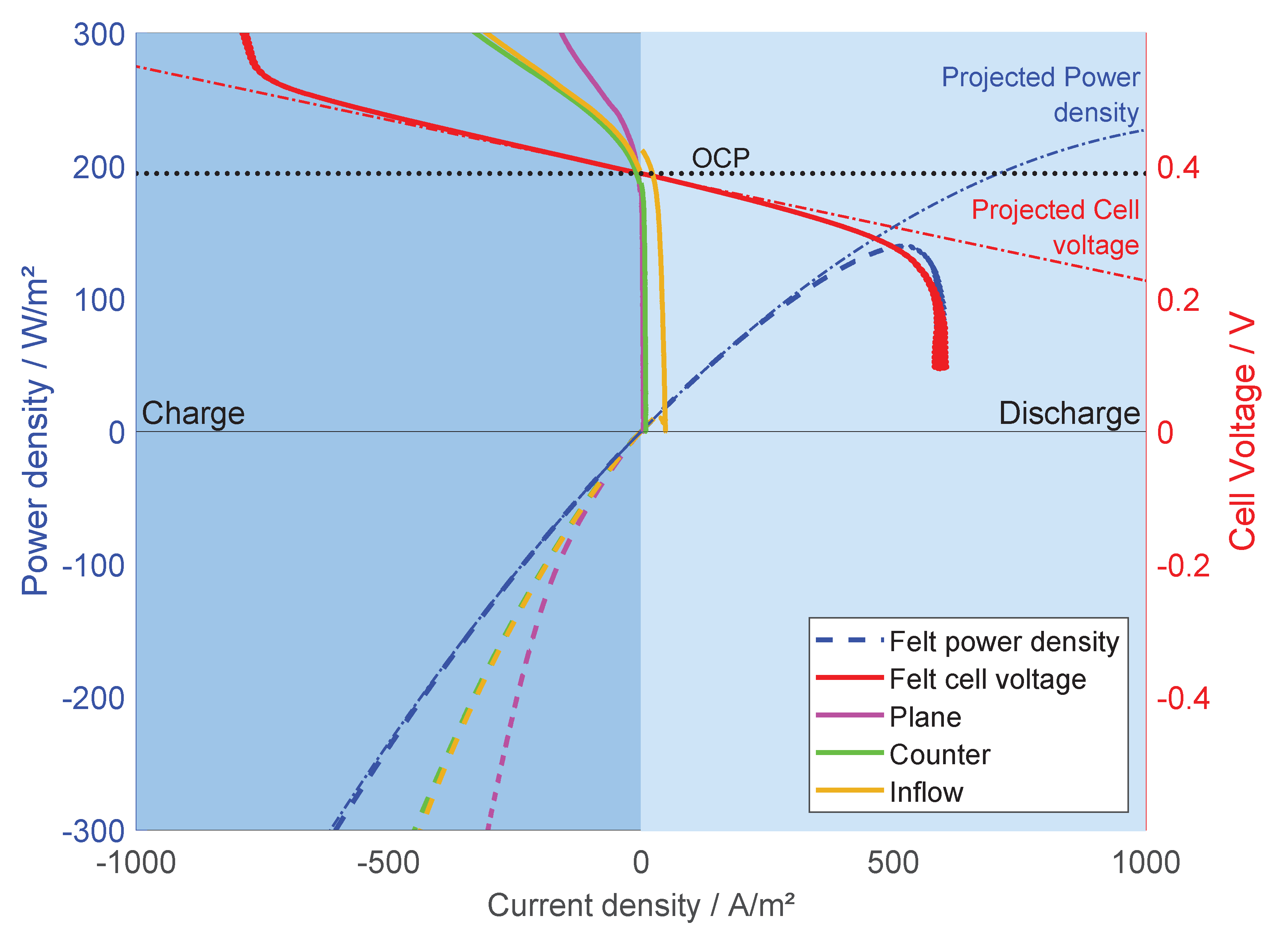
The power of the cell is calculated with the results from the linear sweep voltammetry and plotted versus current density in Figure 6.
The polarization curve for the felt electrode (red dashed line) follows the ideal cell voltage (red dash-dot line) from −800 A/m 2 to about 250 A/m 2 , then starting to deviate and rapidly drop off towards 600 A/m 2 . The other electrodes have a much smaller usable voltage window with steep polarization curves which renders them less useful. The power of the felt electrode (blue solid line) is following the theoretical power (blue dash-dot line) closely in the range (shown here) of −600 A/m 2 to about 250 A/m 2 , then starting to deviate and peaking at around 500 A/m 2 . The other three electrodes reach the maximum power very close to OCP. This suggests that the power is distinctly related to the electrode surface area. To show that the tested system is able to actually store energy, up to 100 charge and discharge cycles were performed and analyzed. To evaluate the possibility of charge and discharge, the battery was set up with plane graphite electrodes. It was then charged and discharged in the voltage range of 0.12–0.77 V with a maximum current of 1 mA. The charge strategy was “constant current constant voltage” as the cell is not optimized and the resistance of the cell is big compared to its size.
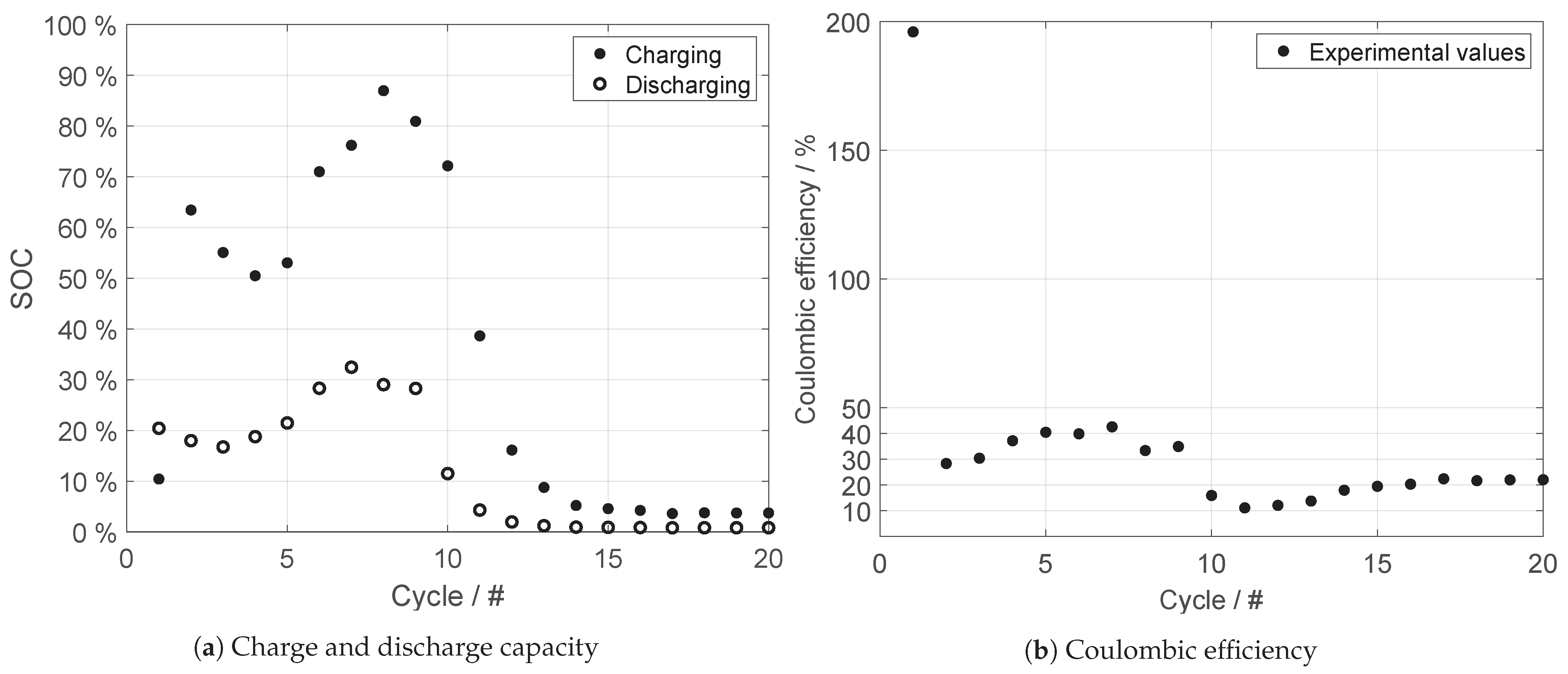
In Figure 7a the charge and discharge loads are shown versus the number of cycles, with the Coulombic efficiency ( η c = Q discharge / Q charge ) for these cycles in Figure 7b.
The coulombic efficiency of cycling was obtained with open beakers. It should be repeated with closed beakers (foil on top) and while purged with nitrogen/argon/inert gas. Oxygen/air contamination is probably the reason for low efficiency. The discharge capacity of the battery in the first 10 cycles varies in a range of 16–32% of SOC. From cycle 10 and onward the discharge capacity decreases steadily. From cycle 14 on the discharge capacity is at about 1% of SOC and stays constant until cycle 20. It is likely that from here on only the double layer was charged and discharged due to significant degradation of the electrolyte and the electrodes.
Figure 7b shows that the FeCl concentration cell is chargeable and dischargeable, but with a low coulombic efficiency. As the battery was set up with nearly charged electrolyte the first cycle has an efficiency above 100 %. The battery was not fully charged for each cycle. This allows to perform this amount of cycles with a low coulombic efficiency. The discrepancy between 100 % and the calculated coulombic efficiency is energy spent in side reactions and is likely damaging the battery. In this case sediments on the electrode surfaces were visible after 55 cycles. The sediments are likely oxidation layers, or classical rust, from a precipitation reaction.

Outlook and Research Needs

Future design optimization will increase the performance, decrease electrical resistance and enhance fluid flow. Especially the following points need to be addressed:
  • Increase the surface area of the carbon felt electrode and tailor them to the needs of this system to increase power output;
  • Investigate different inhibitors and other electrolyte stabilizing measures to increase cyclability;
  • Investigate and understand the scalability of the system, both in terms of cell cross sectional area, flow rates and stacking;
  • Investigate different membranes in terms of permselectivity of ions and water transport.

5. Conclusions

In this study, we have proven the concept of using iron chloride (II) and (III) as primary substance for an energy storage concentration cell or battery. We have demonstrated that in principal the cell can be cycled, but that stabilization of the electrolyte is needed, and have given suggestions for further research. In this study, we have also shown that by using porous carbon fibre electrodes one can remove most of limitations that prevent utilising the maximum power density of the cell and that this is a path to follow in the continuation of developing this concentration cell battery. We have also shown that future studies of kinetics with respect to cycling stability and general system performance are needed. Using an electrode with a larger surface area will decrease the resistance of charge transfer further and thus contribute to higher voltage levels over the entire current density spectrum. Concerning the cyclability, the literature reports that measures exist to stabilize iron-based electrolytes, such as the addition of organic acids like citric acid or ascorbic acid. Furthermore, the purging of the electrolytes with an inert gas will decrease the oxidation rate and will also contribute to better long-term stability.

Author Contributions

Conceptualization, O.S.B. and B.K.; Methodology, O.S.B.; Validation, B.K. and B.S.-V.; Formal Analysis, R.B., B.K. and O.S.B.; Investigation, B.K. and B.S.-V.; Resources, B.S.-V.; Data Curation, R.B. and B.K.; Writing—Original Draft Preparation, R.B. and B.K; Writing—Review & Editing, O.S.B.; Visualization, R.B.; Supervision, O.S.B.; Project Administration, B.K. and O.S.B.; Funding Acquisition, B.K. and O.S.B. All authors have read and agreed to the published version of the manuscript.

Funding

This research received no external funding.

Data Availability Statement

The data presented in this study are available on request from the corresponding author.

Acknowledgments

R.B. would like to thank NTNU for awarding him a Postdoctoral Research Fellowship. B.K. would like to thank the E.ON Stipendienstiftung for financing. We thank Kristina Lopez Hatlen for performing many of the experiments in this work during her time in our lab.

Conflicts of Interest

The authors declare no conflict of interest.

References

  1. Weber, A.Z.; Mench, M.M.; Meyers, J.P.; Ross, P.N.; Gostick, J.T.; Liu, Q. Redox flow batteries: A review. J. Appl. Electrochem. 2011, 41, 1137–1164. [Google Scholar] [CrossRef] [Green Version]
  2. Skyllas-Kazacos, M.; Cao, L.; Kazacos, M.; Kausar, N.; Mousa, A. Vanadium Electrolyte Studies for the Vanadium Redox Batter—A Review. ChemSusChem 2016, 9, 1521–1543. [Google Scholar] [CrossRef]
  3. Burheim, O.S. Engineering Energy Storage, 1st ed.; Academic Press: Cambridge, MA, USA, 2017. [Google Scholar]
  4. Hoberecht, M.; Thaller, L. Design Flexibility of Redox Flow Systems; Technical Report No. NASA-TM-82854; NASA Lewis Research Center: Cleveland, OH, USA, 1982.
  5. Pletcher, D.; Wills, R. A novel flow battery—A lead acid battery based on an electrolyte with soluble lead (II): III. The influence of conditions on battery performance. J. Power Sources 2005, 149, 96–102. [Google Scholar] [CrossRef]
  6. De Leon, C.P.; Frías-Ferrer, A.; González-García, J.; Szánto, D.; Walsh, F.C. Redox flow cells for energy conversion. J. Power Sources 2006, 160, 716–732. [Google Scholar] [CrossRef] [Green Version]
  7. Cheng, J.; Zhang, L.; Yang, Y.S.; Wen, Y.H.; Cao, G.P.; Wang, X.D. Preliminary study of single flow zinc–nickel battery. Electrochem. Commun. 2007, 9, 2639–2642. [Google Scholar] [CrossRef]
  8. Lai, Q.; Zhang, H.; Li, X.; Zhang, L.; Cheng, Y. A novel single flow zinc–bromine battery with improved energy density. J. Power Sources 2013, 235, 1–4. [Google Scholar] [CrossRef]
  9. Skyllas-Kazacos, M. New All-Vanadium Redox Flow Cell. J. Electrochem. Soc. 1986, 133, 1057. [Google Scholar] [CrossRef]
  10. Rychcik, M.; Skyllas-Kazacos, M. Characteristics of a new all-vanadium redox flow battery. J. Power Sources 1988, 22, 59–67. [Google Scholar] [CrossRef]
  11. Skyllas-Kazacos, M. Efficient Vanadium Redox Flow Cell. J. Electrochem. Soc. 1987, 134, 2950. [Google Scholar] [CrossRef]
  12. Shi, Y.; Eze, C.; Xiong, B.; He, W.; Zhang, H.; Lim, T.; Ukil, A.; Zhao, J. Recent development of membrane for vanadium redox flow battery applications: A review. Appl. Energy 2019, 238, 202–224. [Google Scholar] [CrossRef]
  13. Schwenzer, B.; Zhang, J.; Kim, S.; Li, L.; Liu, J.; Yang, Z. Membrane Development for Vanadium Redox Flow Batteries. ChemSusChem 2011, 4, 1388–1406. [Google Scholar] [CrossRef]
  14. Kim, K.J.; Park, M.S.; Kim, Y.J.; Kim, J.H.; Dou, S.X.; Skyllas-Kazacos, M. A technology review of electrodes and reaction mechanisms in vanadium redox flow batteries. J. Mater. Chem. A 2015, 3, 16913–16933. [Google Scholar] [CrossRef]
  15. Shaheen, S.M.; Alessi, D.S.; Tack, F.M.; Ok, Y.S.; Kim, K.H.; Gustafsson, J.P.; Sparks, D.L.; Rinklebe, J. Redox chemistry of vanadium in soils and sediments: Interactions with colloidal materials, mobilization, speciation, and relevant environmental implications—A review. Adv. Colloid Interface Sci. 2019, 265, 1–13. [Google Scholar] [CrossRef] [PubMed]
  16. Post, J.W.; Veerman, J.; Hamelers, H.V.; Euverink, G.J.; Metz, S.J.; Nymeijer, K.; Buisman, C.J. Salinity-gradient power: Evaluation of pressure-retarded osmosis and reverse electrodialysis. J. Membr. Sci. 2007, 288, 218–230. [Google Scholar] [CrossRef] [Green Version]
  17. Ramon, G.Z.; Feinberg, B.J.; Hoek, E.M. Membrane-based production of salinity-gradient power. Energy Environ. Sci. 2011, 4, 4423–4434. [Google Scholar] [CrossRef]
  18. Kingsbury, R.S.; Chu, K.; Coronell, O. Energy storage by reversible electrodialysis: The concentration battery. J. Membr. Sci. 2015, 495, 502–516. [Google Scholar] [CrossRef]
  19. Krakhella, K.W.; Bock, R.; Burheim, O.S.; Seland, F.; Einarsrud, K.E. Heat to H2: Using Waste Heat for Hydrogen Production through Reverse Electrodialysis. Energies 2019, 12, 3428. [Google Scholar] [CrossRef] [Green Version]
  20. Krakhella, K.W.; Morales, M.; Bock, R.; Seland, F.; Burheim, O.S.; Einarsrud, K.E. Electrodialytic Energy Storage System: Permselectivity, Stack Measurements and Life-Cycle Analysis. Energies 2020, 13, 1247. [Google Scholar] [CrossRef] [Green Version]
  21. Manohar, A.K.; Kim, K.M.; Plichta, E.; Hendrickson, M.; Rawlings, S.; Narayanan, S.R. A High Efficiency Iron-Chloride Redox Flow Battery for Large-Scale Energy Storage. J. Electrochem. Soc. 2015, 163, A5118–A5125. [Google Scholar] [CrossRef]
  22. Yensen, N.; Allen, P.B. Open source all-iron battery for renewable energy storage. HardwareX 2019, 6, e00072. [Google Scholar] [CrossRef]
  23. Silverman, J.; Dodson, R.W. The Exchange Reaction between the Two Oxidation States of Iron in Acid Solution. J. Phys. Chem. 1952, 56, 846–852. [Google Scholar] [CrossRef]
  24. Zlotorowicz, A.; Strand, R.V.; Burheim, O.S.; Wilhelmsen, Ø.; Kjelstrup, S. The permselectivity and water transference number of ion exchange membranes in reverse electrodialysis. J. Membr. Sci. 2017, 523, 402–408. [Google Scholar] [CrossRef] [Green Version]
  25. Melin, T.; Rautenbach, R. Membranverfahren: Grundlagen der Modul-und Anlagenauslegung; Springer: Berlin/Heidelberg, Germany, 2007. [Google Scholar]
  26. Nagarale, R.; Gohil, G.; Shahi, V.K. Recent developments on ion-exchange membranes and electro-membrane processes. Adv. Colloid Interface Sci. 2006, 119, 97–130. [Google Scholar] [CrossRef] [PubMed]
  27. Aaron, D.; Liu, Q.; Tang, Z.; Grim, G.; Papandrew, A.; Turhan, A.; Zawodzinski, T.; Mench, M. Dramatic performance gains in vanadium redox flow batteries through modified cell architecture. J. Power Sources 2012, 206, 450–453. [Google Scholar] [CrossRef]
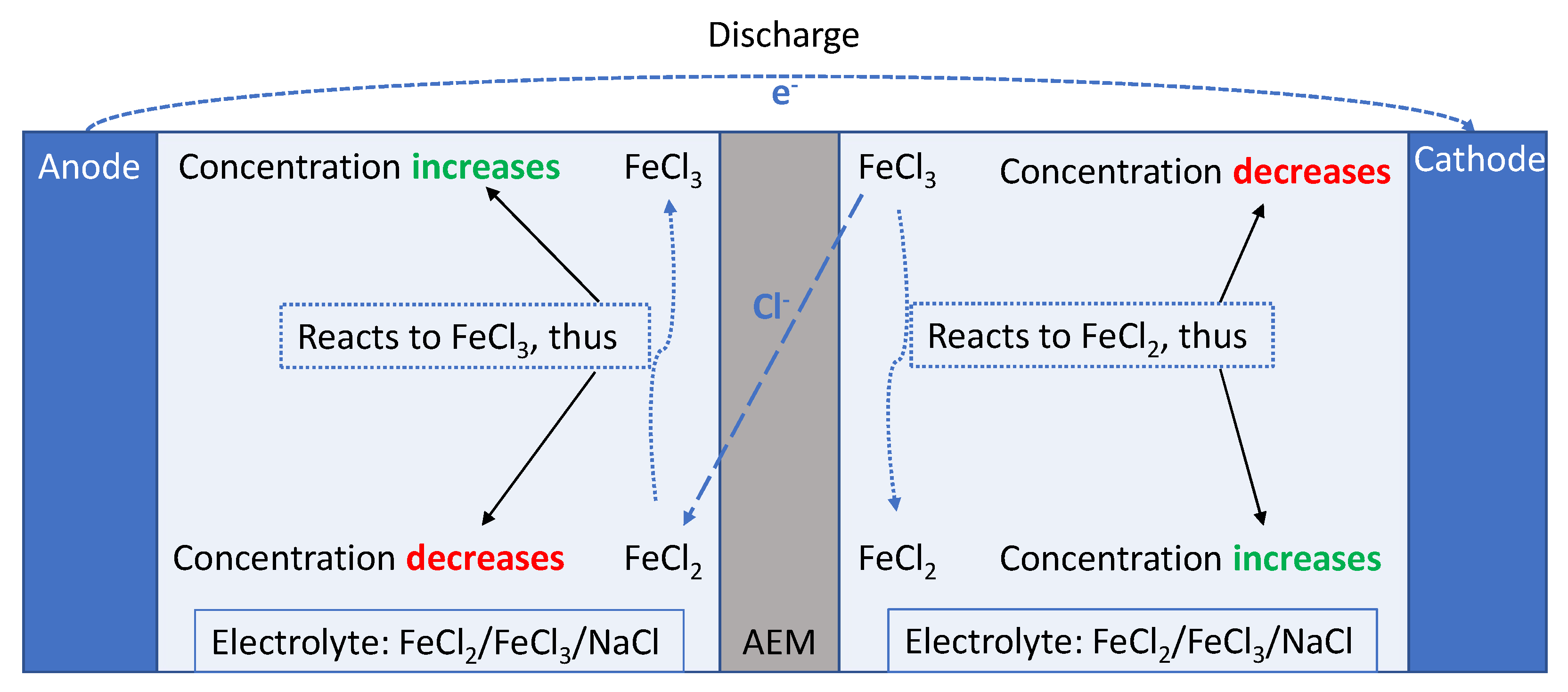
Figure 1. Cell mechanism at discharge until concentration ratio of FeCl 2 /FeCl 3 is 1 on both sides.
Energies 14 01109 g001
Figure 2. Illustration of the flow cell setup. (a) Setup schematic (b) Photograph with peristaltic pump and solutions in the background.
Energies 14 01109 g002
Figure 3. Four different graphite electrodes setups are used in the experiments.
Energies 14 01109 g003
Figure 4. Measured open circuit potentials with the carbon fiber felt electrodes at different concentration ratios of FeCl 2 / FeCl 3 and temperatures.
Energies 14 01109 g004
Figure 5. Measured β s at different temperatures and FeCl 2 / FeCl 3 concentration ratios with quadratic fits.
Energies 14 01109 g005
Figure 6. Power density in respect to current density and polarisation curve of the flow cell for the four electrode types. Negative current density values denote charging of the cell, positive current density values denote discharging.
Energies 14 01109 g006
Figure 7. Capacities and efficiencies for the first 20 cycles of the FeCl concentration cell.
Energies 14 01109 g007
Table 1. Overview of the used concentrations and their respective states of charge (SOC).
FeCl 2 FeCl 3 NaClSOC
mol/Lmol/Lmol/L%
0.99950.0005199.95
0.9950.005199.50
0.950.05194.74
0.90.1188.89
0.50.510
0.10.9188.89
0.050.95194.74
0.0050.995199.50
0.00050.9995199.95
Publisher’s Note: MDPI stays neutral with regard to jurisdictional claims in published maps and institutional affiliations.