Article

Numerical Study of Spray-Induced Turbulence Using Industrial Fire-Mitigation Nozzles

1
DES-DM2S-STMF, CEA, Université Paris-Saclay, 91191 Gif-sur-Yvette, France
2
Institute for Applied Sciences, INSA Rouen Normandie, Clean Combustion Laboratory, CORIA UMR 6614 CNRS, 76000 Rouen, France
3
EDF R&D, Fluid Dynamics Power Generation and Environment, 78401 Chatou, France
4
Aix Marseille University, LIS UMR 7020 CNRS, F-13397 Marseille, France
*
Author to whom correspondence should be addressed.
Energies 2021, 14(4), 1135; https://doi.org/10.3390/en14041135
Submission received: 13 January 2021 / Revised: 4 February 2021 / Accepted: 10 February 2021 / Published: 20 February 2021
(This article belongs to the Section K: State-of-the-Art Energy Related Technologies)

Abstract

:
A numerical investigation of the spray-induced turbulence generated from industrial spray nozzles is carried out to better understand the roles of the nozzle spray on the fires or explosions in different accidental scenarios. Numerical simulations are first validated against experimental data in the single nozzle case using the monodisperse and polydisperse assumption for droplet diameters. The polydispersion of the nozzle spray is proven to be necessary to correctly predict the gas and droplet velocities. The turbulent kinetic energy has dominant values inside the spray cone, decreases rapidly with the vertical distance from the spray nozzle, and is strongly affected by the spray droplet diameter. On the contrary, the integral length scale is found to have high values outside the spray cone. Two interacting sprays injected from different nozzles are then investigated numerically using the validated polydisperse model. The water sprays generated from such industrial nozzles can generate turbulence of high intensity in the near-nozzle region, and this intensity decreases with the distance from the nozzles. A better understanding of the turbulence generated by the spray system can be beneficial for the evaluation of several important phenomena such as explosion enhancement. The guideline values obtained from this investigation of single and double nozzles can be useful for large-scale numerical simulations.

1. Introduction

Water spray systems are commonly used as emergency devices for fire mitigation purposes in gas processing plants [1], power plants, and offshore platforms [2]. These systems play essential roles in the prevention of severe industrial accidents, such as explosions of hydrogen or other gas fuels [3]. Different flame propagation regimes may exist during the explosion, such as fast deflagration or detonation, depending on the fuel, water steam concentration, as well as ambient pressure and temperature distribution [4]. Various experimental and numerical studies show that the spray systems can have effective mitigation effects on the flame propagation as a result of water droplet evaporation [5,6]. However, the explosion enhancement can also be observed in some experimental studies, due to the spray-generated turbulence in the gas mixture [7]. Thus, an estimation of the turbulence intensity induced by the water spray is needed to evaluate the overall mitigation or enhancement ability of the water spray during accidental explosions.
Spray- or particle-induced turbulence has been an active research field for several decades [8,9,10,11,12,13]. The presence of spray droplets or particles in the gas can disturb and change the intrinsic turbulence topology of the carrier flow, which is known as turbulence modulation [14]. Several important factors arise that contribute to the turbulence modulation such as [14,15]: droplet surface, inertia, response, and mass loading. For the case where the carrier phase has a non-zero intrinsic turbulence intensity, the presence of a particle or droplet cloud may have two opposite effects: turbulence attenuation or enhancement [16]. Some criteria are proposed to distinguish between these two opposite effects, such as the length scale ratio [17], the particle momentum number P a [18], etc. For the system without intrinsic turbulence, the spray injection can directly generate turbulent fluctuations in the gas system.
Numerical evaluations of the turbulent intensity induced by an industrial fire mitigation water spray are scarcely available in the literature. Many factors are involved in the physical modeling, such as the water flow rate, droplet size distribution, injection velocity, etc. These factors are usually coupled and have different values depending on the nozzle types. The water spray generated from an industrial nozzle has a polydisperse nature. Spray droplets directly generated from the nozzle can have diameters varying from 10 m to 1000 m [19,20]. Spray nozzles are often placed in linear or circular rows in the dome of a building, as shown in Figure 1. The interaction of the spray droplets generated from different nozzles can be important, leading to the droplet collision, coalescence, etc. [21,22]. This might change the droplet size distributions, as well as the turbulent parameters in the spray interaction zone. Far from the spray nozzle, the typical value of the spray droplet volume fraction is reported to be α = O ( 10 4 ) in industrial applications [23], for which the collisions of the droplets can be neglected [24]. For simplicity, solid particles are often used instead of water droplets in many experimental and numerical investigations [25,26,27,28,29,30]. Compared to water droplets, solid particles are easier to control and have less complicated interaction mechanisms.
In terms of the numerical simulation of the spray-/particle-induced turbulence, different approaches exist according to the geometrical scale of the problem. Spray injection of very small scales can be simulated using highly-resolved Direct Numerical Simulations (DNSs) [31]. For a variety of engineering applications, the Large Eddy Simulation (LES) models are widely applied [32] for fuel spray injection in engines of a geometry scale of O (10 cm). However, the industrial fire mitigation water sprays have much larger geometries ( O (1–10 m)) than the fuel sprays in combustion. Moreover, these two approaches can hardly be applied directly in engineering applications of large-scale geometries as a result of important computational costs. An example of the large-scale simulations can be hydrogen explosions in a nuclear containment building (volume V = 10 4 10 5 m 3 ) or offshore facilities (volume V = 10 5 10 6 m 3 ). The smallest grid sizes for these problems can be around Δ x O ( 10 cm ) , and the direct application of these highly-resolved turbulence models, involving the action of spray and spray-flame interaction, can give erroneous results. The description of spray-induced turbulence in the current commercial engineering code is mostly based on empirical correlations where several factors are user-defined using a set of experimental data and are strongly case-dependent [33]. In this study, we try to use the Reynolds-Averaged Navier–Stokes (RANS) models to evaluate the turbulence generated from one single and two interacting industrial spray nozzles in order to find guideline values for the turbulence intensity in large-scale simulations. The RANS models are widely used for the evaluation of turbulence in many industrial applications [34]. Important parameters are investigated here such as the turbulence kinetic energy and the integral length scale of turbulence.
The objectives of this paper are threefold: (i) evaluation using RANS models of spray-induced turbulence; (ii) investigation of the effects of the spray polydispersion model on the spray-induced turbulence intensity; (iii) qualitative study of the turbulence induced by two interacting sprays generated from two separate nozzles. Section 2 gives the basic assumptions and governing equations of the numerical modeling; Section 3 presents the numerical investigations on the single nozzle spray, containing the mesh grid choice, code validation, as well as the simulation results for both the monodisperse and polydisperse spray of a single nozzle; the study of two interacting sprays is carried out and presented in Section 4; finally, conclusions and perspectives are given in Section 5.

2. Numerical Modeling

2.1. Modeling Assumptions

The following assumptions and simplifications are made in the numerical simulations: (i) the spray droplets are considered to be inert, spherical, rigid particles with constant heat capacity and a uniform temperature distribution; (ii) the volume fraction of the particles is relatively small so that the collision between particles is neglected; (iii) the viscous drag forces and gravity are supposed to act on the particles. The Basset force is neglected, since the particle-to-gas density ratio is high O ( 10 3 ) and the acceleration of particles by the gas flow is small [35]. It is assumed that the particles do not spin; thus, the Magnus force is neglected.

2.2. Governing Equations

The NEPTUNE_CFD code is a Navier–Stokes solver developed jointly by EDF (Électricité de France) and CEA (Commissariat à l’Énergie Atomique et aux Énergies Alternatives) for three-dimensional multi-fluid flows [36,37]. Different turbulence models are implemented in this solver such as the k- ε model, the R i j - ε model, etc. NEPTUNE_CFD relies on a finite volume discretization and can use various mesh types (tetra- or hexa-hedral) for different flow regimes: steady/unsteady, compressible/incompressible, laminar/turbulent.
The governing equations for the two-phase system in Neptune_CFD consist of mass, momentum, and energy conservation laws. The mass conservation equation can be expressed as [38]:
t ( α κ ρ ¯ κ ) + · ( α κ ρ ¯ κ V ¯ κ ) = Γ κ , κ = l , g ,
where α κ denotes the volume fraction of the phase κ , ρ ¯ κ is the mass density, V ¯ κ is the local mean velocity of the phase κ , Γ κ is the interphase mass transfer rate, and l and g denote the liquid and gas phases, respectively.
The momentum conservation gives:
t ( α κ ρ ¯ κ V ¯ κ ) + · ( α κ ρ ¯ κ V ¯ κ 2 ) = α κ p ¯ + M κ + α κ ρ ¯ κ f g + · [ α κ ( τ ¯ κ + τ ¯ κ T ) ] , κ = l , g ,
where p ¯ is the gas pressure, f g the gravity acceleration, M κ the interphase momentum transfer term, and τ ¯ κ , τ ¯ κ T denote the viscous and Reynolds stress tensors, respectively [39].
The total enthalpy conservation has the expression:
t α κ ρ ¯ κ h ¯ κ + V ¯ κ 2 2 + · α κ ρ ¯ κ h ¯ κ + V ¯ κ 2 2 V ¯ κ = α κ p ¯ t + α κ ρ ¯ κ f g V ¯ κ + Γ κ h ¯ κ , i n t + V ¯ κ 2 2 + q κ A i n t + q w k · [ α κ ( q ¯ κ + q ¯ κ T ) ] .
where h κ stands for the phase-averaged specific enthalpy for the phase κ , h ¯ κ , i n t the interfacial-averaged enthalpy, and Γ κ and q κ A i n t denote the interfacial transfer of mass and heat, respectively. q w k is the wall-to-fluid heat transfer flux term, and the turbulent heat fluxes in phase κ are represented by q ¯ κ and q ¯ κ T , respectively. The flow quantities to resolve are α κ , ρ κ , V κ , and h κ . More discussions about this two-phase model and turbulent closure laws of different terms can be found in [36,40].
The k- ε turbulence model is used in this study for the description of the gas turbulence. The turbulent variables solved are the turbulent kinetic energy k and the turbulent dissipation rate ε , with the k equation:
ρ ¯ g k t + d i v ρ ¯ g V ¯ g k μ g + μ t σ k g r a d k = P + G ρ ¯ g ε + k d i v ( ρ ¯ g V ¯ g ) ,
The equation for ε reads:
ρ ¯ g ε t + d i v ρ ¯ g V ¯ g ε μ g + μ t σ ε g r a d ε = C ε 1 ε k P + ( 1 C ε 3 ) G ρ ¯ g C ε 2 ε 2 k + ε d i v ( ρ ¯ g V ¯ g ) ,
where P is the shear stress production term:
P = ρ ¯ g R i , j V ¯ g , i x j
G represents the gravity term:
G = 1 ρ ¯ g μ t σ t ρ ¯ g x i g i
The eddy viscosity is:
μ t = ρ ¯ g C μ k 2 ε
with the constants C μ = 0.09 ; C ε 1 = 1.44 ; C ε 2 = 1.92 ; σ k = 1 ; σ ε = 1.3 ; and C ε 3 = 1 .

3. Study of a Single Spray Nozzle

3.1. Spray Nozzle

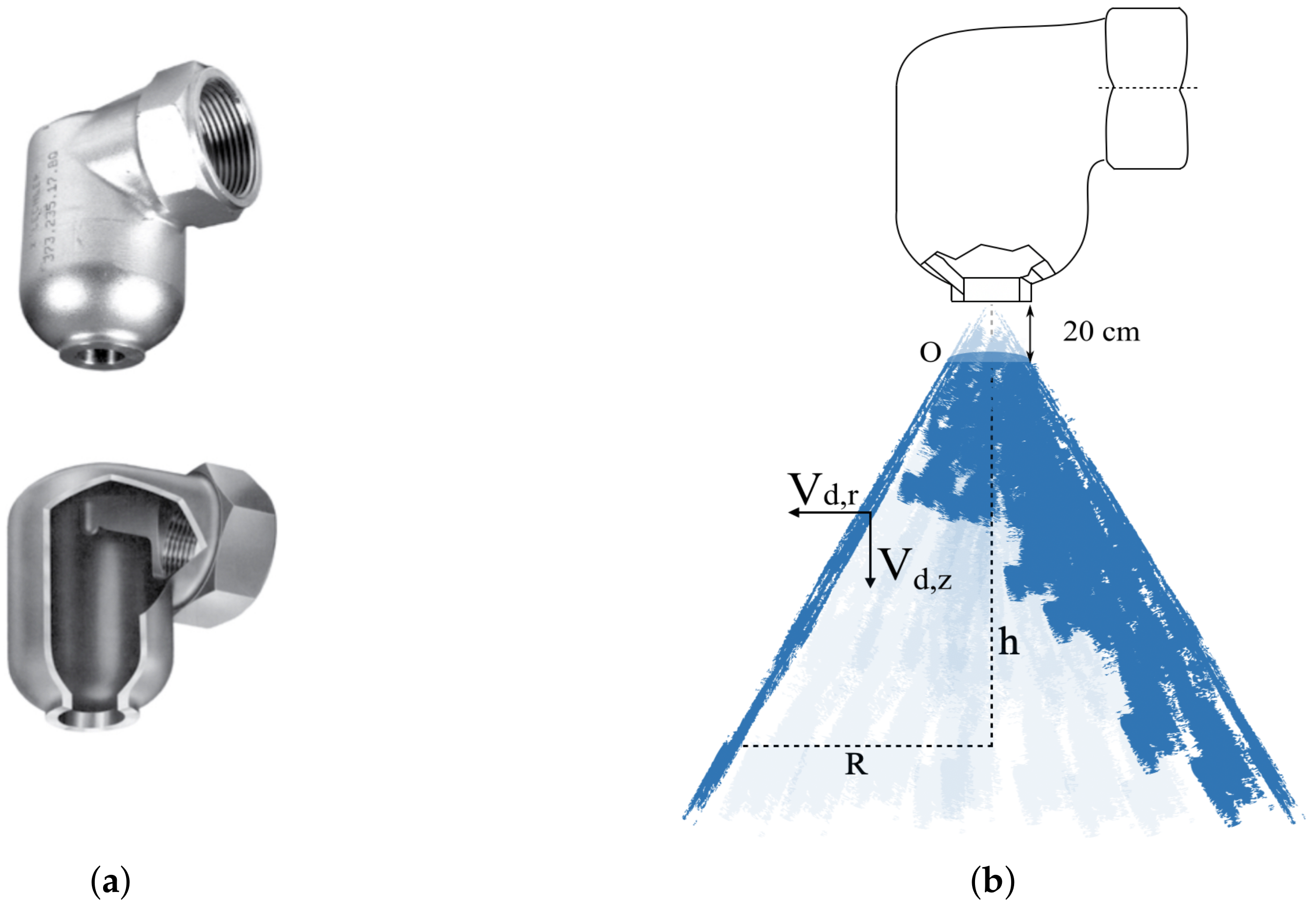
A nozzle commonly used for industrial fire mitigation applications, the nozzle SPRACO 1713A (ref. 373.084.17.BN), shown in Figure 2a [41], is considered. This ramp bottom nozzle can be applied for gas cooling and mixing, dust suppression, etc. The spray generated from the nozzle has the shape of a hollow cone, as shown in Figure 2b. The axial distance from nozzle is denoted as h, while R represents the radial distance from the spray central line. Spray droplets from the nozzle have diameters ranging from 50 m to 1000 m with a mean Sauter diameter of 300 m, with a mass injection rate of 1 kg/s.

3.2. Geometry, Mesh, and Spray Characteristics

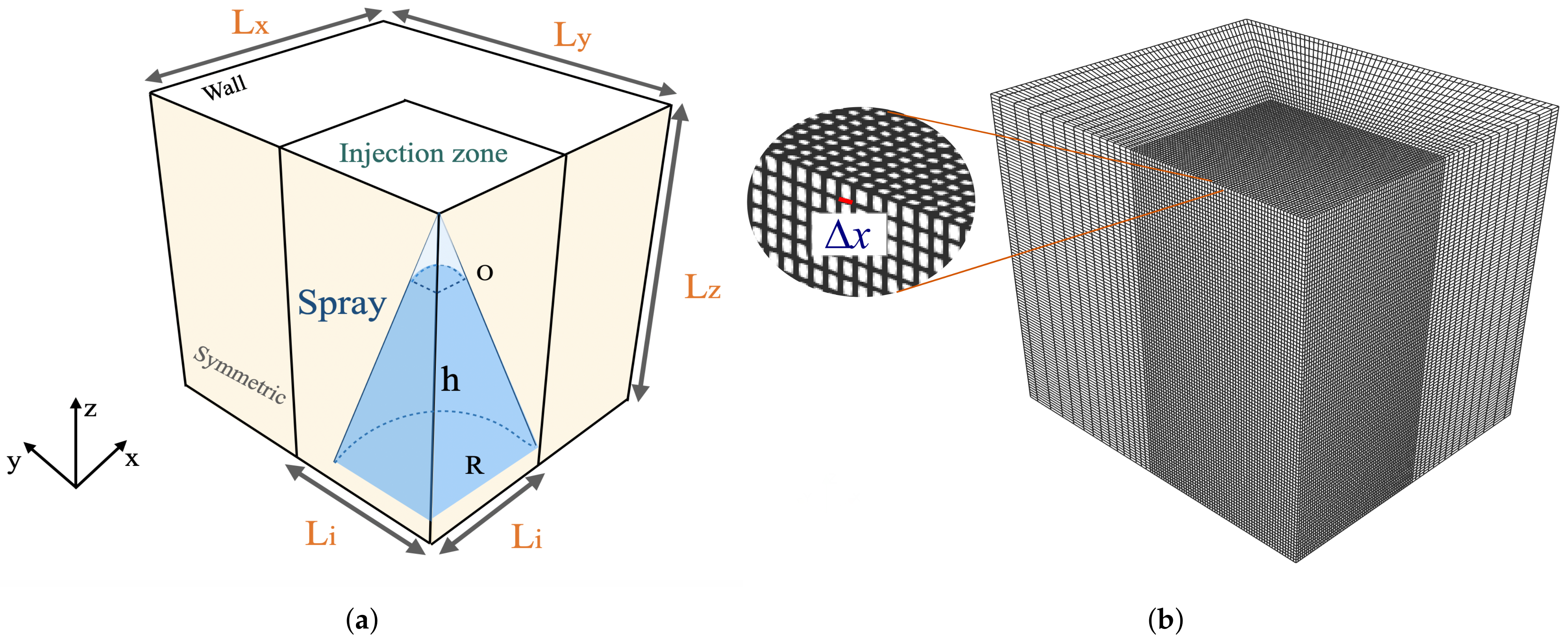
The numerical geometry is a cuboid with a size of 3 × 3.5 × 3.5 m 3 , representing a quarter of the spray domain, as shown in Figure 3. A spray injection zone is refined around the nozzle central line as depicted in Figure 3a. Symmetric boundary conditions are set on the two vertical surfaces crossed by the centerline of the spray nozzle, shown in yellow in Figure 3a. Wall conditions are set to the other boundaries of the geometry for the gas phase. The bottom of the geometry is set to be a free outlet of the droplets. Different mesh sizes are used in the injection region ranging from Δ x = 3 cm to Δ x = 0.67 cm. An example of the mesh grid is illustrated in Figure 3b.
In the numerical simulations, the primary atomization of the water ligaments out of the nozzle is not considered. The spray droplets are considered to be spherical, solid particles, which are injected at a distance h = 20 cm from the nozzle with initial axial and radial velocities obtained from experimental measurements [42,43]. The droplets are injected in a circular ring between R = 8 cm and R = 15 cm. In order to simplify the simulation, the deformation, breakup, evaporation, and coalescence of the droplets are not considered. Two different spray models are implemented and compared in this section: monodisperse and polydisperse models for the droplet diameter distribution.
In the monodisperse case, the spray droplets share a uniform diameter of 300 m with an injection mass flow rate of 1 kg/s. The initial axial and radial velocities of the droplets are 17.7 m/s and 7.6 m/s, respectively. In the polydisperse case, the droplets are divided into nine classes, each having different diameters (55 m, 166 m, 277 m, 388 m, 499 m, 611 m, 722 m, 833 m, and 944 m), as shown in Table 1. The injection velocities of the nine different classes of droplets are determined by experimental measurements.

3.3. Simulation Convergence

3.3.1. Mesh Size Effects

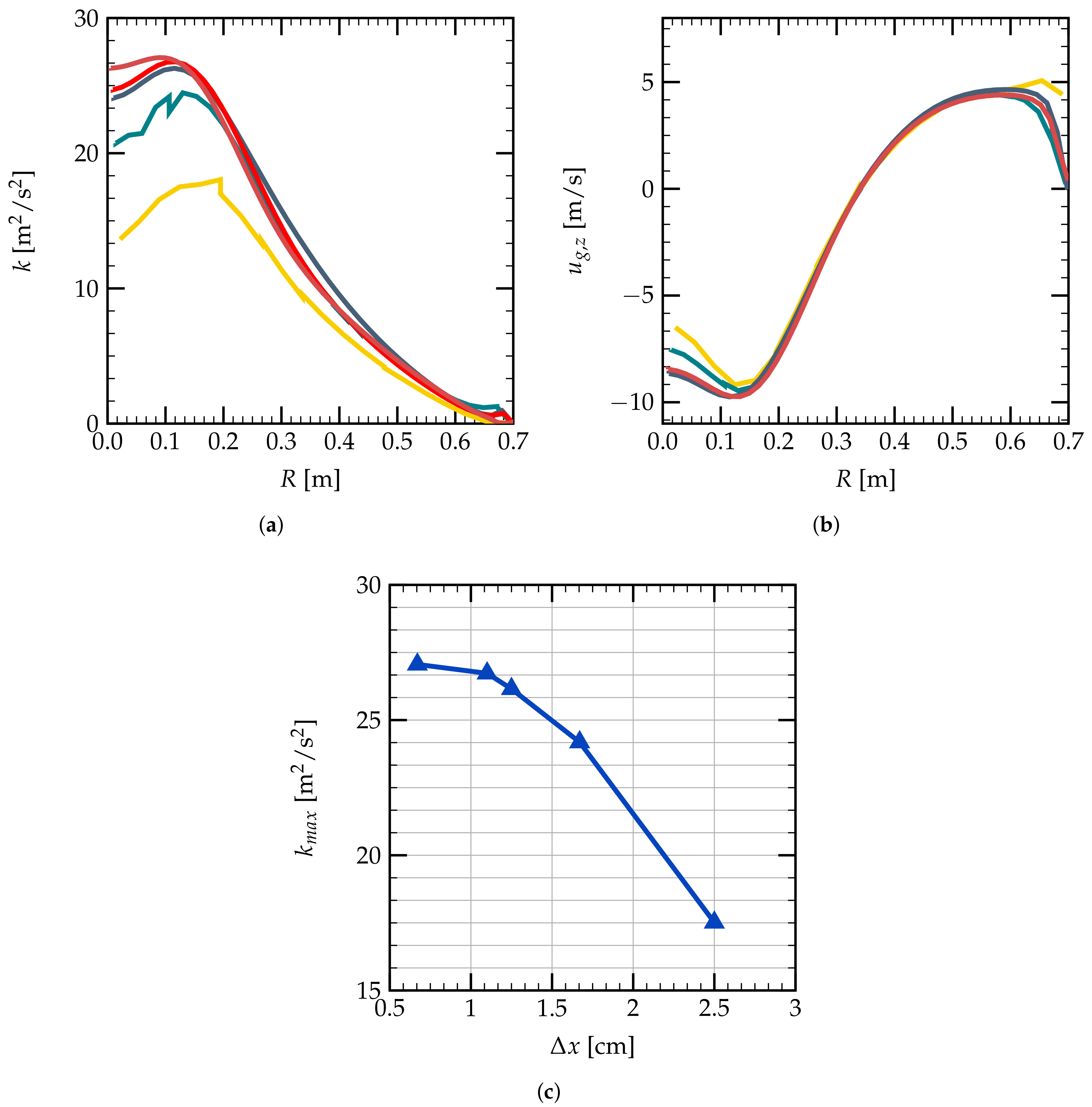
The mesh convergence study is performed using the monodisperse spray model for the grids of different mean mesh sizes in the injection region, ranging from D e l t a x = 0.67 cm to D e l t a x = 2.5 cm, as shown in Figure 4. The evolutions of the turbulent kinetic energy as a function of radial distance R are presented in Figure 4a. The convergence of k with the mean mesh size can be seen more clearly in Figure 4c, where one can see that k tends to converge when the mean mesh size becomes smaller than Δ x = 1 cm. Figure 4b shows the axial gas velocity evolutions for different mesh sizes. The droplet and gas velocities, as well as the droplet volume fractions are noted to be less sensitive to the variation of the mesh sizes.
Considering the computational cost, the mesh grid of a mean size of Δ x = 1.5 cm in the spray injection region is used in the following simulations for both the mono- and poly-dispersion cases. From Figure 4c, with Δ x = 1.5 cm, one can have a good order of magnitude of the turbulence kinetic energy k.

3.3.2. Time Convergence

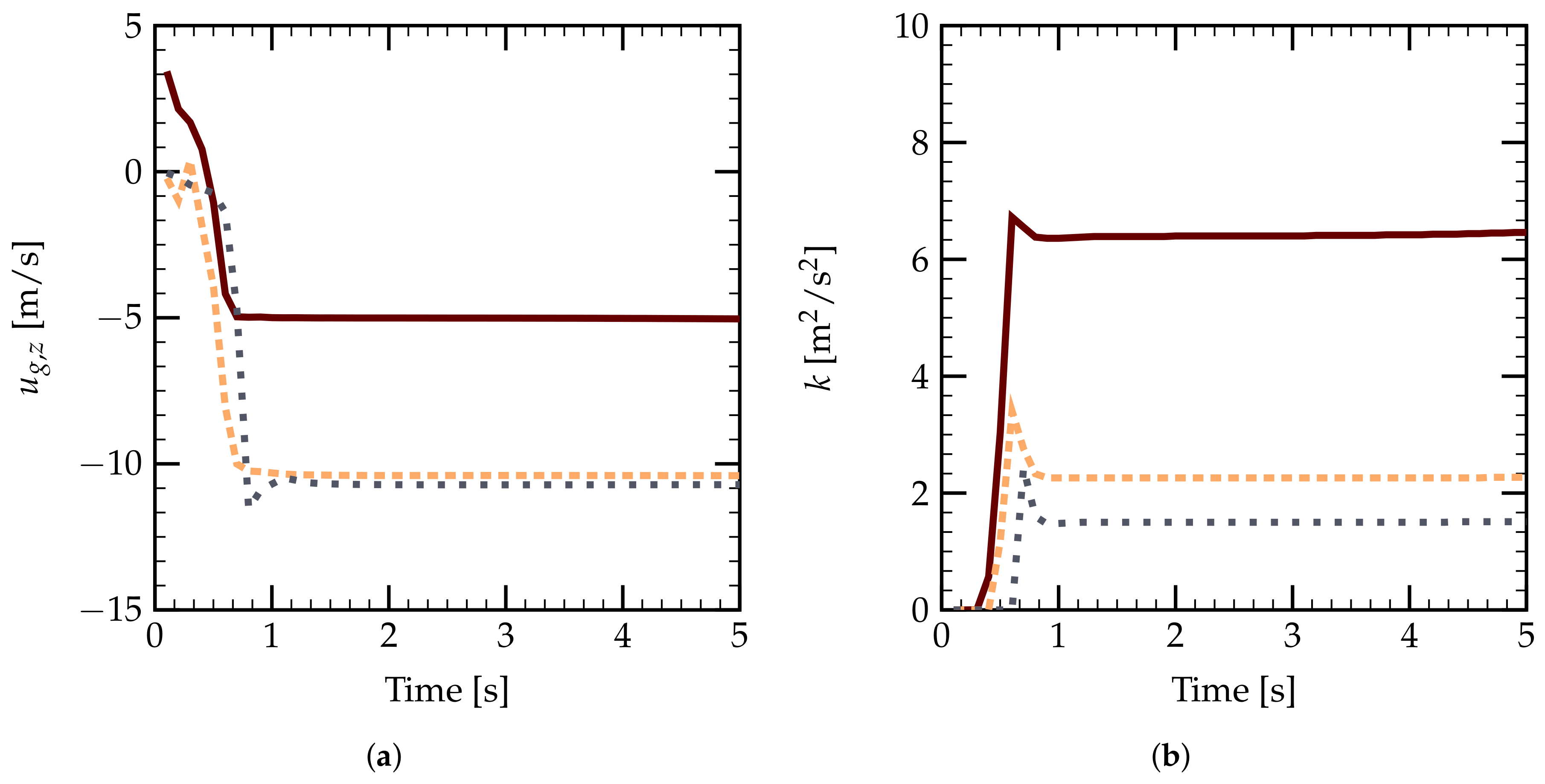
The temporal convergence of k and gas axial velocity is presented in Figure 5. Three numerical point probes are set inside the spray cone to record the evolution of the temporal gas properties. These results are obtained with the monodisperse spray for a calculation time t = 10 s with time step Δ t = 0.001 s in a refined grid of mean mesh size Δ x = 1.5 cm.
Figure 5a gives the temporal evolution of the axial gas velocity u g , z for three probe positions, having vertical coordinates of h = 0.5 m, 1.5 m, and 2.3 m from the nozzle, respectively. One can see that steady states are obtained very quickly after about 1.5 s of injection for the monodisperse spray. The evolutions of turbulent kinetic energy k also show a quasi-steady state after 1 s, as shown in Figure 5b. Generally, we observe a time convergence for these numerical simulations for a simulation time of 10 s.

3.4. Code Validation

We begin with the validation of the Neptune_CFD code on the velocity of the gas and droplets using the measurements of CALISTexperiments [42,43]. The results of the numerical simulations of the single nozzle spray performed in the work of Foissac et al. [21] are also used as references.

3.4.1. Monodisperse Spray

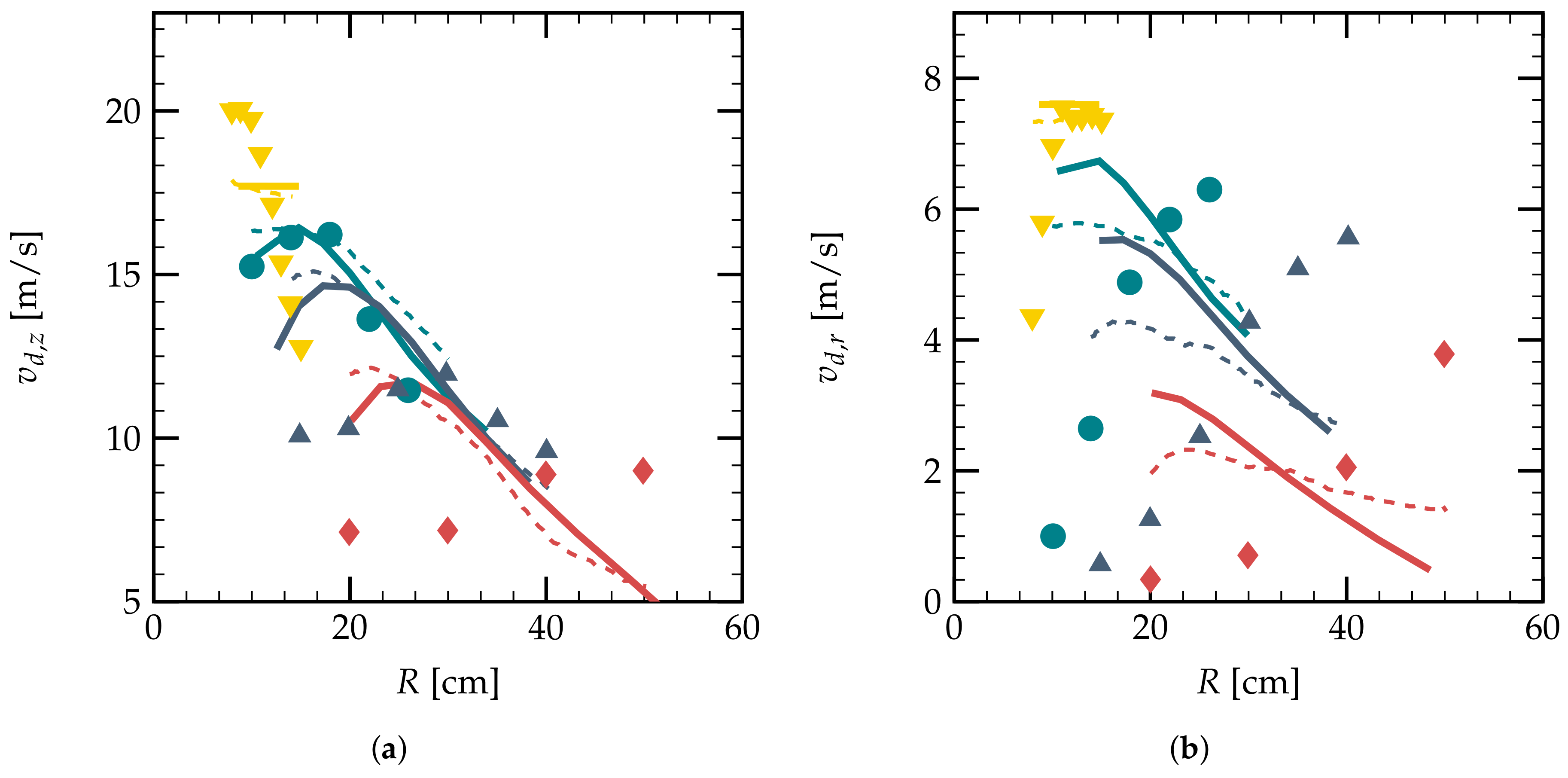
The validation of the monodisperse case is performed for t = 10 s using the grid of mean mesh size Δ x = 1.5 cm, as presented in Figure 6. Figure 6a shows the droplet velocity at different vertical distances h = 20 cm, 40 cm, 60 cm, and 95 cm as a function of axial distance R. One can see that the current calculations have a good agreement with the reference numerical simulations of [21] for the axial velocity of droplets. However, the tendency of the droplet velocity given by the numerical simulations is not correct compared to the experimental measurements. This is due to the fact that the monodisperse assumption using a mean value for all spray droplet diameters is not sufficient to predict the dynamics of a real spray.
Figure 6b gives the radial velocity evolution of the droplets at different vertical distances from the spray nozzle h. The numerical calculations can give a rough estimation of the order of magnitude of the experimental results. However, the tendency of the velocity is quite different. The monodisperse assumption is too strong for the simulation of a real spray.

3.4.2. Polydisperse Spray

For the polydisperse spray modeling, we have nine different diameters for the droplets, each of which has its own velocity behavior after injection. The mean velocity of all classes of droplets v ¯ d can be a representative quantity. Two definitions can be reasonable in this context, either averaged by the volume fraction of each droplet class or averaged by the number of droplets in a given calculation cell. In this study, the number-averaged spray velocity is used for the polydisperse spray. It is emphasized that the cells with a very small quantity ( α t o t < 1 × 10 6 ) of droplets are neglected during the calculations of the mean velocity.
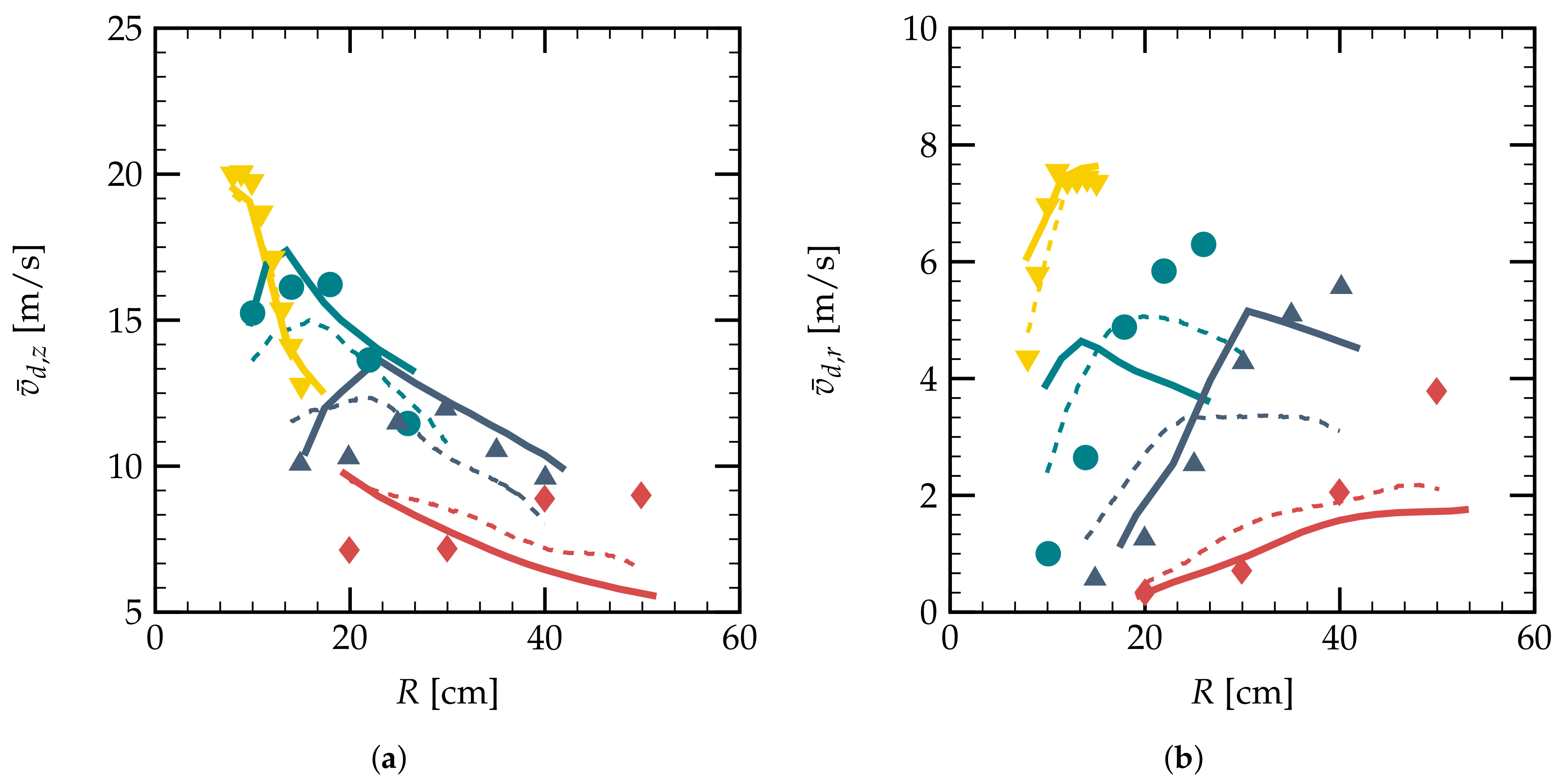
Figure 7a shows the mean axial velocity of droplets at different positions along the z axis. One can note that the numerical results have similar behaviors for vertical distances h < 60 cm compared to the experimental measurements. Even though the results for h = 95 cm give the opposite tendency, one can still have the same order of magnitude for the axial velocities at different radial distances. Compared to the experimental measurements, the current numerical results for the vertical droplet velocity can have a mean relative error of 3.3 % for h = 20 cm, 7.6 % for h = 40 cm, 12.88 % for h = 60 cm, and 27 % for h = 95 cm. The relative error increases with the vertical distance of measurement.
The evolutions of the radial components of the mean droplets’ velocity are presented in Figure 7b. The relative errors for the droplet radial velocities in the polydisperse spray are larger than the axial velocities. The current numerical results have the same order of magnitude as the experimental results and the numerical results of Foissac [21]. For h = 20 , 60, and 95 cm, the tendency of the radial velocity matches the experimental data.
Comparing Figure 7 to Figure 6, one can deduce that the consideration of the spray polydispersion can significantly improve the estimation accuracy on the different components of the droplet velocities. Comparing to the former study, we have numerical results of similar accuracy with a less dense mesh grid. The good estimation of both the droplet and gas dynamics is essential for the determination of the turbulence intensity induced by the water spray.

3.5. Turbulent Properties of the Monodisperse Spray

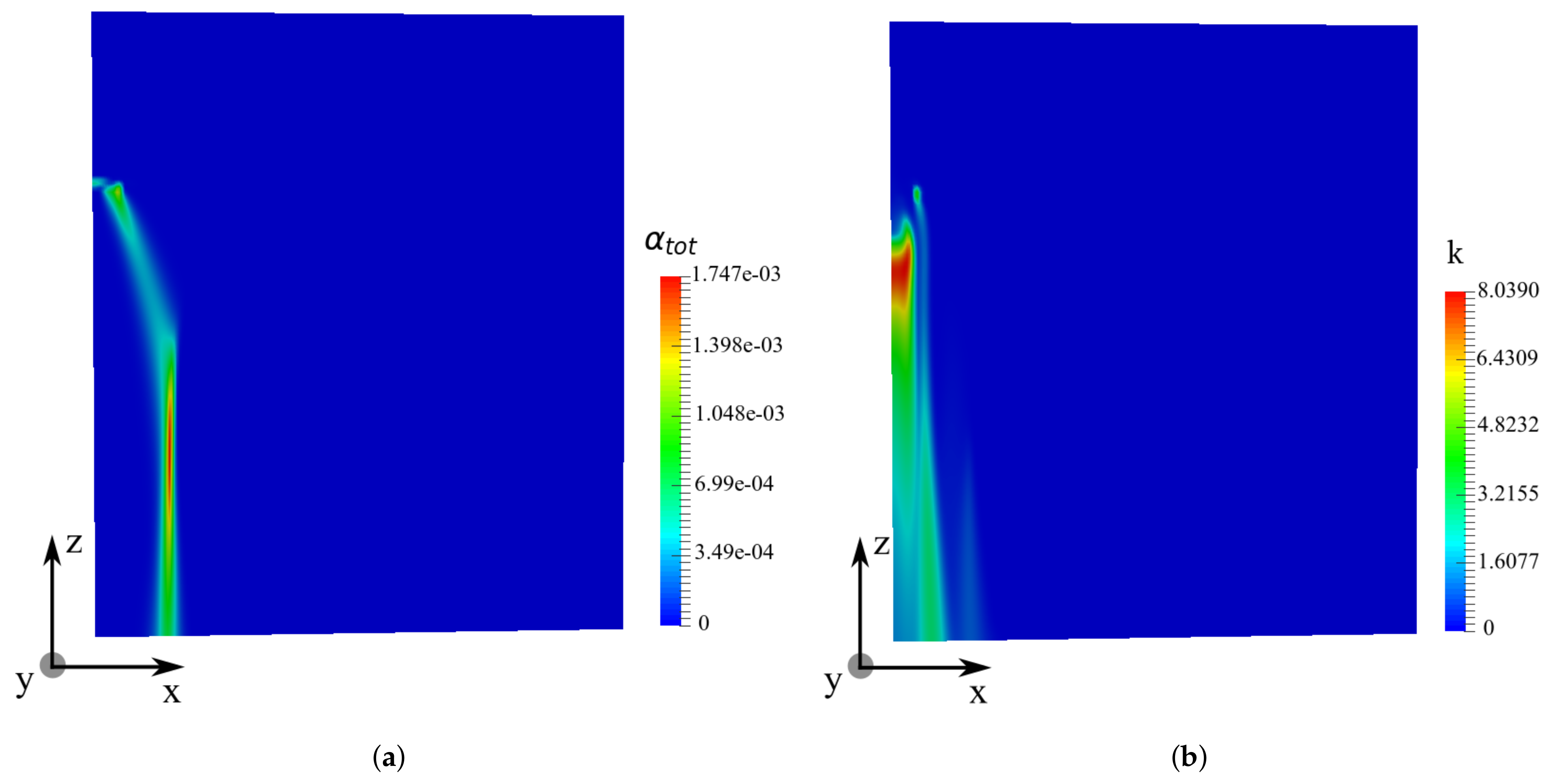
Figure 8 shows the spatial distribution of droplet volume fraction α t o t and turbulent kinetic energy k for the monodisperse spray injected from a single nozzle. One can see a side view of the droplet volume fraction distribution on the XZplane with y = 0.05 m, in Figure 8a. The droplets of diameter 300 m form a hollow spherical cone after being injected. Then, the radial velocity decreases, and the spray cone has a constant diameter far from the spray nozzle. The turbulent kinetic energy is noted to have high values inside this spray cone, as shown in Figure 8b. With an increasing vertical distance from the spray nozzle, the turbulent kinetic energy k decreases from 8 m 2 / s 2 near the nozzle to 1 m 2 / s 2 at h = 2 m.

3.6. Turbulent Properties of the Polydisperse Spray

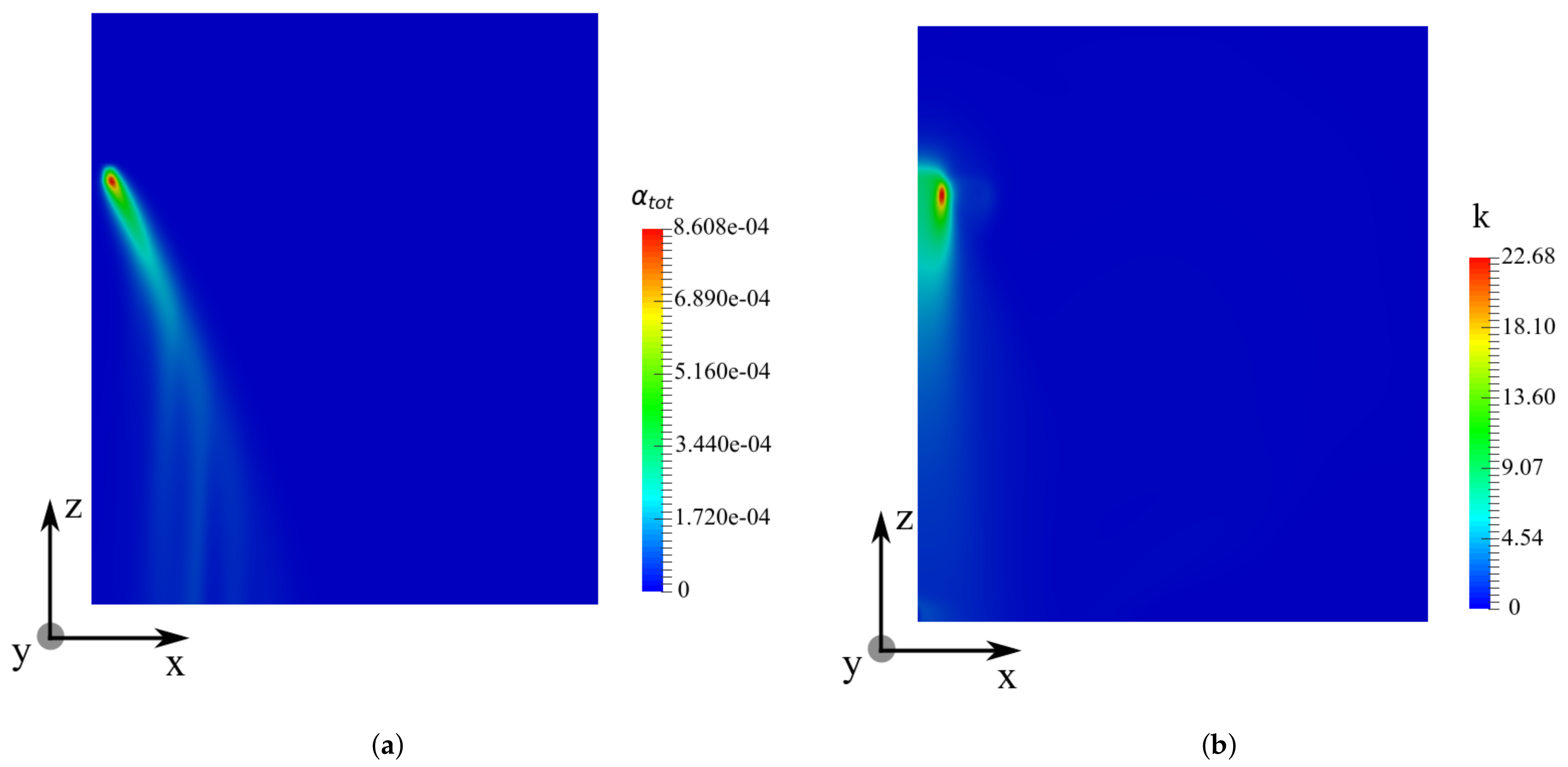
Figure 9 presents the numerical results of α t o t and k on the XZ plane at y = 0.05 m for t = 10 s. The same mesh grid is used in the simulations for Figure 8 and Figure 9. One can see the total liquid volume fraction distribution in Figure 9a. Large droplets are noted to be dominant on the outer rim of the spray cone, whereas the small ones are retained on the inner side of the spray.
Comparing to the monodisperse case, the spray cone is larger in the polydisperse spray. The spatial distribution of the turbulent kinetic energy k is presented respectively in Figure 9b. Comparing to Figure 9a, we can find that the region where k has high values is located inside the spray cone, which is the same for the turbulent dissipation rate ε . The turbulence intensity of the air outside the spray cone is less affected by the injection of the spray, which is similar to the monodisperse spray case, as depicted in Figure 8.
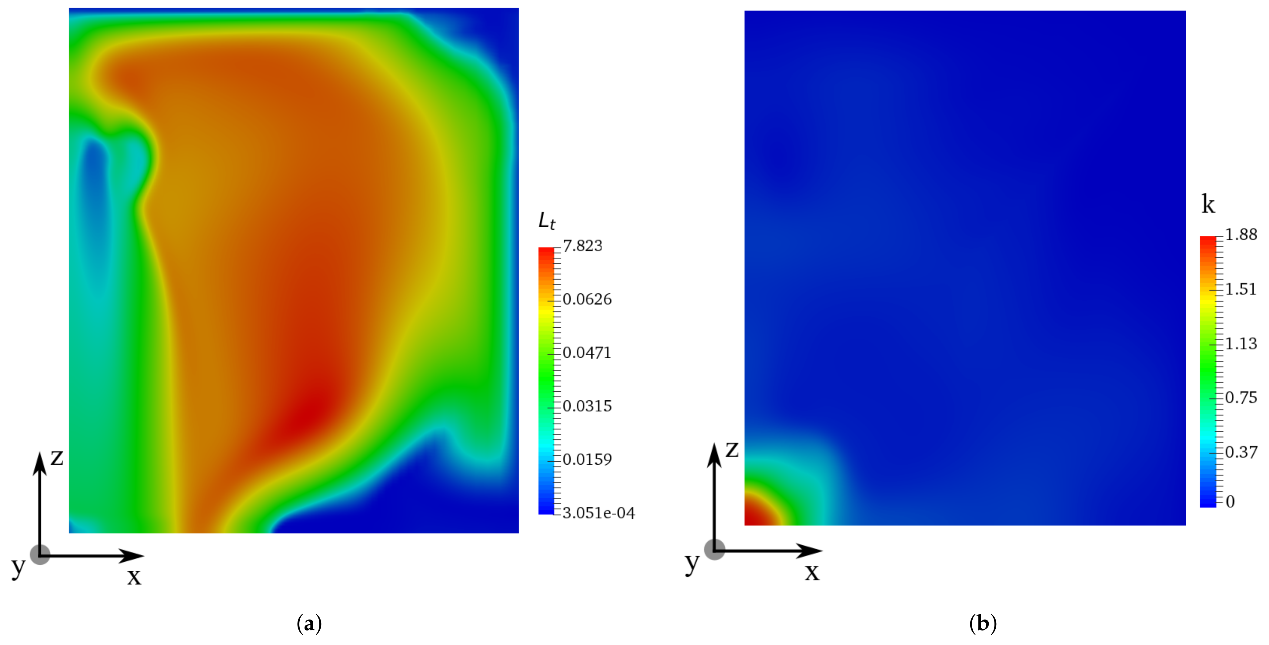
Figure 10 shows the distribution of turbulence integral length scale L t and turbulent kinetic energy k on the XY plane at h = 1.5 m. The integral length scale L t is noted to have high values in the near-field outside the region of the spray cone. Inside the spray cone, L t is relatively small and increases with the vertical distance from the nozzle.
Form Figure 10b, one can see that the turbulent kinetic energy is maximal around the symmetric axis of the geometry, in the center of the spray cone. The turbulent intensity seems to decrease with the radial distance R from the symmetric axis.

3.6.1. Droplet Volume Fraction

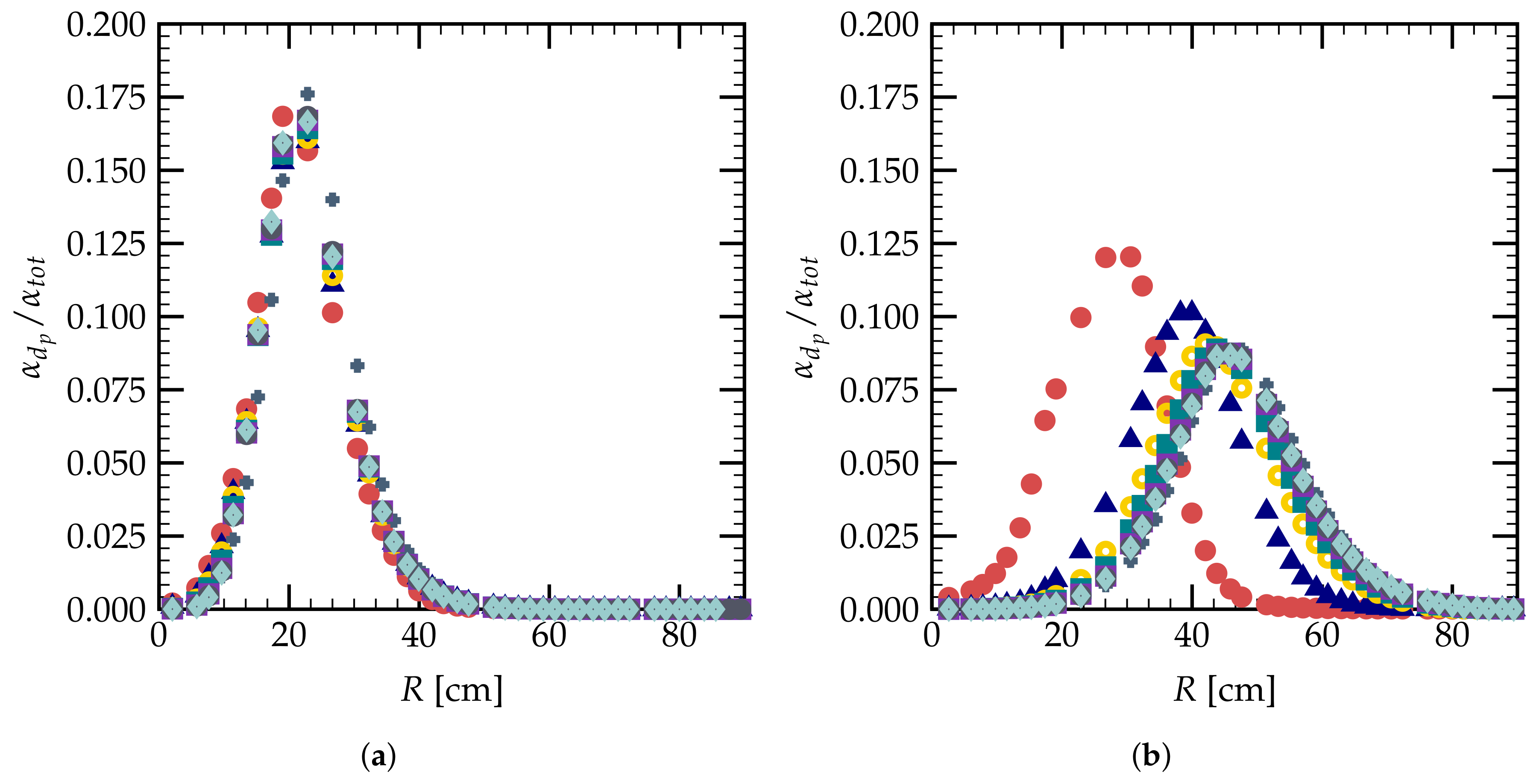
Figure 11 shows the evolutions of the normalized droplet volume fraction for different droplet classes. The distribution of droplet volume fraction α t o t at h = 40 cm is given in Figure 11a. One can see that the droplets of different diameters have almost the same radial distribution at h = 40 cm, where a maximal value at radial distance R 20 cm is noted. However, for h = 95 cm, the maximal values separate for droplets of different diameters. Larger droplets show a maximal volume fraction at a radial distance farther than the small ones. This phenomena is due to the droplet inertia, i.e., with the same initial injection radial velocity, the large droplets need a larger distance to be decelerated by the drag force.

3.6.2. Droplet Size Distribution

From another point of view, Figure 12 shows the histogram of normalized volume and number fractions for different droplets on vertical planes of h = 20 cm and h = 95 cm. These quantities can be important for the turbulence analysis since the spray bulk flow and droplet wake flow can both contribute to the turbulence generation in particle-laden flows [7,44]. One can see that at h = 20 cm, the droplets of diameter between 500 and 600 m have the highest volume fraction compared to the droplets of other diameters in the polydisperse spray. However, smaller droplets of 300–400 m are seen to be dominant in terms of the volume fraction at the plane h = 95 cm, as shown in Figure 12a. For the number fraction, one can see from Figure 12b that the small droplets of d p 300–400 m are dominant at h = 20 cm in terms of droplet numbers. This domination is more significant for the planes farther from the nozzle, such as the plane of h = 95 cm. Thus, small droplets play a more important role in the zone far from the injection nozzle.

3.6.3. Surface-Averaged Volume Fraction

In order to study the vertical distribution of the droplet volume fraction below the spray nozzle, one can introduce the surface-averaged droplet volume fraction α ¯ defined as:
α ¯ = S X Y α d S S X Y
where S X Y is the surface of the plane orthogonal to the axis z, which has a constant value of 10 m 2 in the current geometry for single nozzle simulations.
One can note the evolution of α ¯ as a function of the vertical distance h of the droplets along the z axis in Figure 13a. In both the monodisperse and the polydisperse cases, α ¯ increases with the falling of the droplets. For the monodisperse case, α ¯ increases and converges to a stable value of around 6 × 10 6 . The droplets fall with an initial velocity and accelerate as a result of the gravity, until α ¯ reaches a constant value when the gravity reaches equilibrium with the gas friction. For the polydisperse case, one can see that α ¯ keeps increasing, since for the droplets of large diameters, a larger equilibrium distance of the two forces on the droplets is required.
Figure 13b gives the evolution of the maximal turbulent kinetic energy k m a x as a function of vertical distance h from the spray nozzle. For the polydisperse spray, the turbulent intensity decreases rapidly with the distance from the spray nozzle, which corresponds to Figure 10b. Two regions can be distinguished: within a distance h < 1 m from the nozzle, the turbulence intensity is relatively high, and for h > 1 m, the turbulent kinetic energy decreases to low values. Comparing to the monodisperse spray, the maximal value of k for the polydisperse spray is smaller for a vertical distance h > 0.5 m. As discussed above, the small droplets remain on the inner side of the spray cone, as depicted in Figure 11b. They have small inertia and can very quickly reach their terminal velocity, which is closely related to the turbulence intensity. From Figure 13a, one can see that the small droplets of 300 m have reached their terminal velocities for h > 1 m. The dynamics of small droplets have important impacts on the turbulence intensity inside the spray cone.

4. Study of Two Interacting Nozzles

In this section, two interacting nozzles of polydisperse sprays are investigated numerically. Two polydisperse sprays are injected on the top of the geometry, as shown in Figure 14a, with a horizontal distance of 0.2 m between them. The injected spray droplets can form two hollow spray cones in the lower part. The two sprays have identical injection properties as defined in the polydisperse simulation, except for their positions. A mesh grid with mean mesh size Δ x = 2 cm in the injection region was used for the simulation of the two-nozzle case, as depicted in Figure 14b. The simulation results on the XZ plane of y = 0.05 m are given in Figure 15.
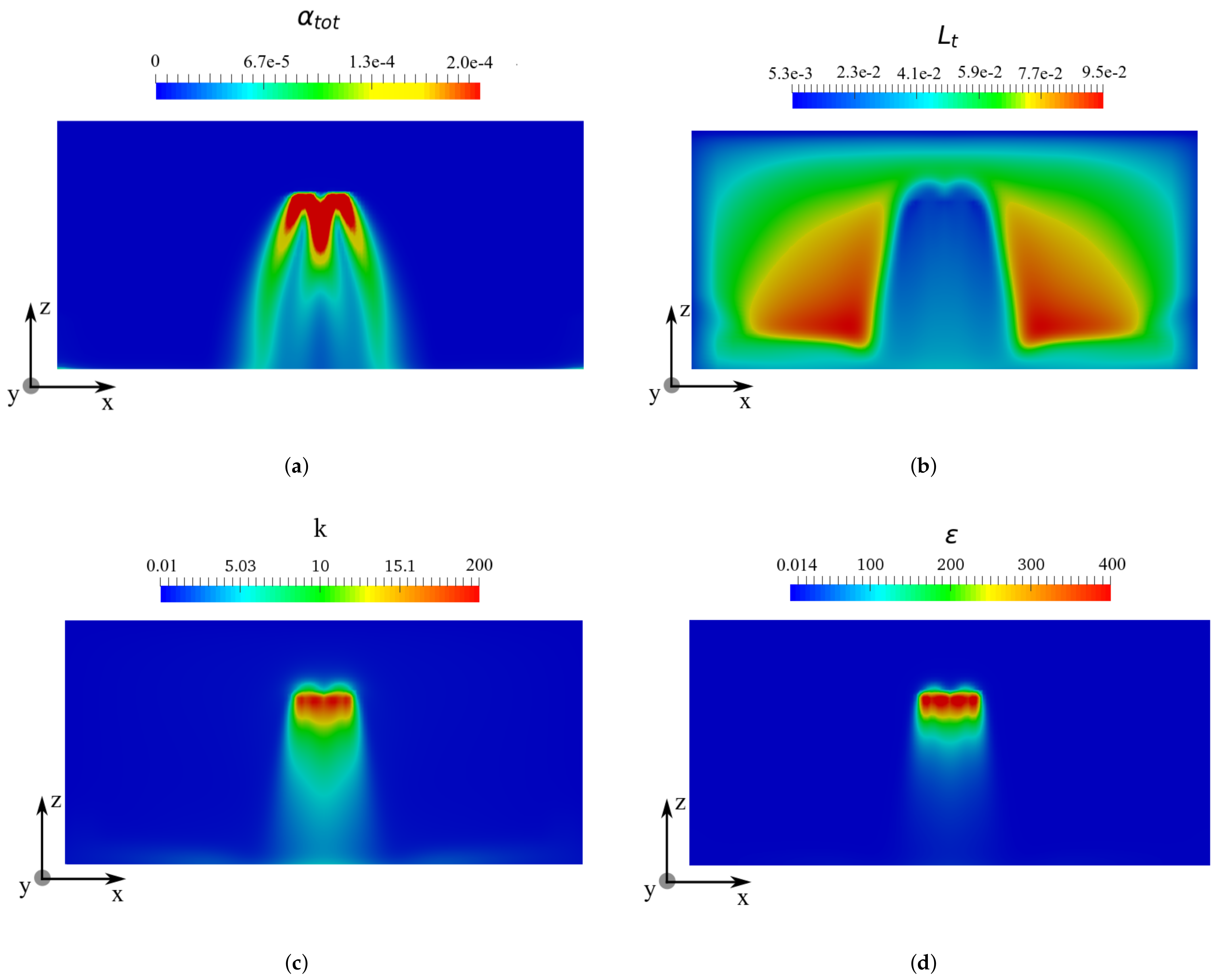
Figure 15a shows the spatial droplet volume fraction distribution on the XZ plane. The spray droplets injected from two nozzles form an intersection region below the injection plane O. Generally, one can see that the droplet volume fraction α t o t decreases with the vertical distance. Figure 15b gives the evolution of the turbulence integral length scale in the case of two interacting sprays. Large droplets are noted to be important in numbers at the outer rim of the two spray cones. Similar to the single nozzle case, the turbulent kinetic energy k and the turbulent dissipation rate ε have high values inside the spray cones, as shown in Figure 15c,d. The droplet collision was considered; however, it is not the main contributor to the turbulence generation in this region. The droplet volume fraction in the interaction region is around O ( 10 4 ) , under which the collision probability can be quite small [10]. The TKE increase in this region is mainly due to the gas flow interaction induced by spray droplets’ movements from the two different nozzles. For the lower region with h > 1 m, the turbulent kinetic energy k, as well as the dissipation rate decrease to a low value.
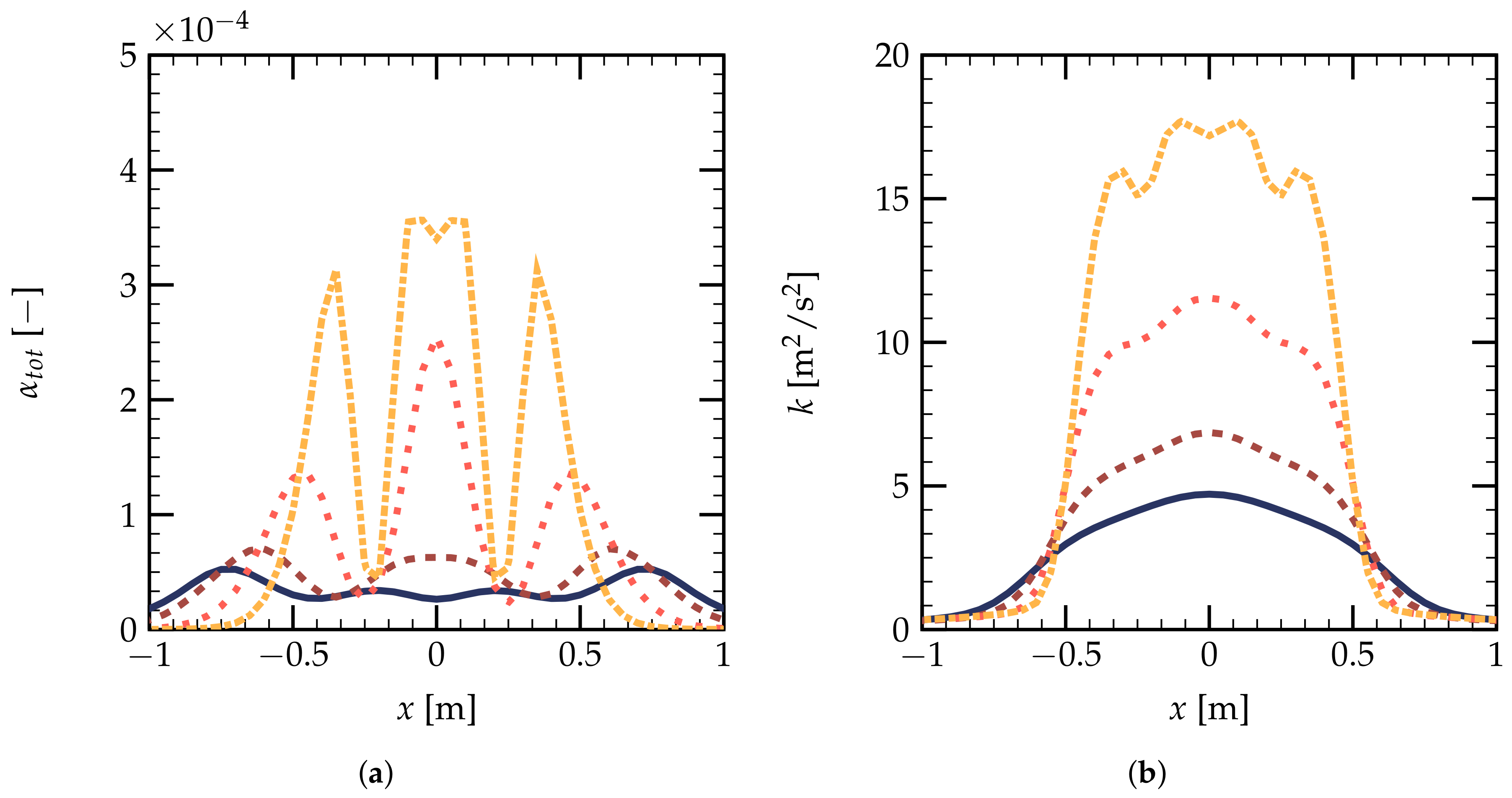
Figure 16 gives the evolutions of droplet volume fraction α t o t and turbulent kinetic energy k as a function of x on the XZ plane at y = 0.05 m. One can see that the interaction of the two polydisperse sprays begins for a vertical distance larger than h = 0.2 m. Figure 16a shows that the droplet volume fraction has three peaks at h = 0.2 m. The interaction zone has a higher value of α t o t than the spray cone generated from a single nozzle. The overall values for α t o t decrease with the vertical distance h, ranging from α t o t = 3.5 × 10 4 to α t o t = 2 × 10 5 . One can see from Figure 16b that the interaction of the spray droplet can locally increase the TKE. Farther from the two spray nozzles, the TKE decreases with the vertical distance h. For h > 1.0 m, the distribution of the TKE becomes more homogeneous compared to the near-nozzle region.
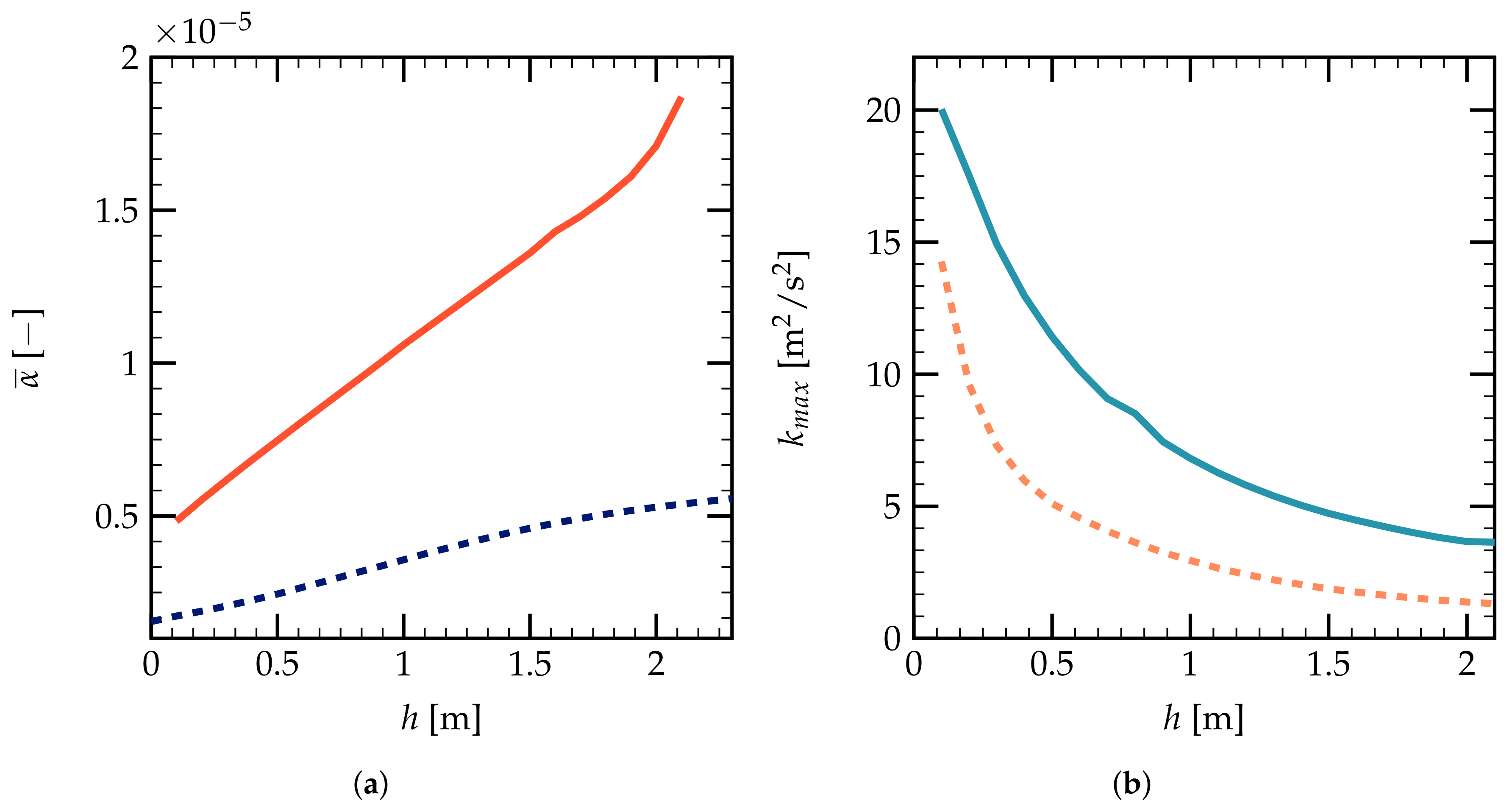
Figure 17a,b shows the evolutions of the surface-averaged droplet volume fraction α ¯ and maximal turbulent kinetic energy k m a x on the XY plane as a function of h. In Figure 17a, α ¯ increases linearly with h, as a result of the polydispersion of droplets generated from the two nozzles. The big droplets have not reached their terminal velocities in this range of vertical distance h. The value of α ¯ is noted to be larger than the single nozzle case shown in the dark blue dashed line. Figure 17b gives the evolution of k m a x on the z direction, which has an analogous trend as the polydisperse spray out of a single nozzle. k m a x has similar values near the spray nozzles; however, one can have a higher value for k m a x for the two-nozzle case than the case of a single nozzle in the far-from-the-nozzle region. This can be due to the fact that the water injection rate is doubled in the two-nozzle case.

5. Conclusions and Perspectives

The spray-induced turbulence generated from industrial nozzles is investigated numerically using an RANS turbulence model. Water sprays injected from a single nozzle, as well as two interacting nozzles are studied both qualitatively and quantitatively. The polydisperse model is proven to be more accurate than the monodisperse one for the evaluation of the gas and droplet velocities. In both the single- and two-nozzle cases, the spray-induced turbulence is noted to be more intense inside the spray cone. The turbulent kinetic energy inside a polydisperse spray seems to be lower than the monodisperse case since the small droplets locate on the inner rim of the polydisperse spray cone, which can diminish the turbulence intensity. The turbulent kinetic energy decreases with the vertical distance from the nozzle, which maintains a low value for a distance larger than 1 m. For large-scale simulations, the near-nozzle region and far-from-the-nozzle region can be simulated separately, since the turbulent properties in the latter region are more homogenous. Comparing the single- and two-nozzle cases, the far-field turbulence intensity is larger with a higher water injection rate. However, the collisions of the droplets have small impacts on the turbulence generation as a result of the low droplet volume fraction in the interaction region. Future studies can be carried out on the effects of water spray on explosive gas-air mixing. The droplet collision effects can be important for nozzles with higher water injection rates.

Author Contributions

Conceptualization, G.G., S.K., and S.M.; methodology, S.K. and A.H.; software, G.G. and S.M.; validation, G.G., S.K., and O.T.; formal analysis, G.G. and O.T.; investigation, G.G. and S.K.; resources, G.G. and S.M.; data curation, G.G., O.T., and S.M.; writing—original draft preparation, G.G. and S.K.; writing—review and editing, S.M., O.T., and A.H.; visualization, G.G. and S.K.; supervision, S.K., A.H., and O.T.; project administration, A.H.; funding acquisition, S.K. All authors read and agreed to the published version of the manuscript.

Funding

This research was funded by Accord Tripartie CEA/EDF/Framatome Institut 2020—F35158.

Institutional Review Board Statement

Not applicable.

Informed Consent Statement

Not applicable.

Data Availability Statement

The data that support the findings of this study are available from the corresponding author upon request.

Acknowledgments

The authors gratefully acknowledge the financial support from Electricité de France (EDF) within the framework of the Generation II & III reactor research program.

Conflicts of Interest

The authors declare no conflict of interest.

Abbreviations

d p Droplet diameter
f g Gravity acceleration
hVertical distance from the spray nozzle
h κ Phase-averaged specific enthalpy for phase κ
k m a x Maximal turbulent kinetic energy
L x , L y , L z Geometry sizes
L t Turbulence integral length scale
MInterphase momentum transfer term
N d p Number of droplets of diameter d p
pGas pressure
P a Droplet momentum number
qHeat transfer flux
RRadius from spray cone center
R i , j Reynolds stress
u g Gas velocity
v p Particle velocity
α t o t Total volume fraction of droplets
α ¯ Surface-averaged droplet volume fraction
ρ Mass density
ε Turbulent dissipation rate
Γ Interphase mass transfer rate
Δ t Time step
Δ x Grid size
DNSDirect Numerical Simulation
RANSReynolds-Averaged Navier–Stokes
LESLarge Eddy Simulation
TKETurbulent Kinetic Energy

References

  1. Landahl, H.; Herrmann, R. Sampling of liquid aerosols by wires, cylinders, and slides, and the efficiency of impaction of the droplets. J. Colloid Sci. 1949, 4, 103–136. [Google Scholar] [CrossRef]
  2. Thomas, G. On the conditions required for explosion mitigation by water sprays. Process. Saf. Environ. 2000, 78, 339–354. [Google Scholar] [CrossRef] [Green Version]
  3. Gai, G.; Kudriakov, S.; Hadjadj, A.; Studer, E.; Thomine, O. Modeling pressure loads during a premixed hydrogen combustion in the presence of water spray. Int. J. Hydrogen Energy 2019, 44, 4592–4607. [Google Scholar] [CrossRef] [Green Version]
  4. Kudriakov, S.; Dabbene, F.; Studer, E.; Beccantini, A.; Magnaud, J.; Paillère, H.; Bentaib, A.; Bleyer, A.; Malet, J.; Porcheron, E.; et al. The TONUS CFD code for hydrogen risk analysis: Physical models, numerical schemes and validation matrix. Nucl. Eng. Des. 2008, 238, 551–565. [Google Scholar] [CrossRef] [Green Version]
  5. Wingerden, K.; Wilkins, B. The influence of water sprays on gas explosions. Part 2: Mitigation. J. Loss Prevent. Proc. 1995, 8, 61–70. [Google Scholar] [CrossRef]
  6. Gai, G.; Kudriakov, S.; Rogg, B.; Hadjadj, A.; Studer, E.; Thomine, O. Numerical study on laminar flame velocity of hydrogen-air combustion under water spray effects. Int. J. Hydrogen Energy 2019, 44, 17015–17029. [Google Scholar] [CrossRef]
  7. Wingerden, K.; Wilkins, B. The influence of water sprays on gas explosions. Part 1: Water-spray-generated turbulence. J. Loss Prevent. Proc. 1995, 8, 53–59. [Google Scholar] [CrossRef]
  8. Hetsroni, G.; Sokolov, M. Distribution of mass velocity and intensity of turbulence in a two-phase turbulent jet. ASME J. Appl. Mech. 1971, 38, 315–327. [Google Scholar] [CrossRef]
  9. Hetsroni, G. Particles-turbulence interaction. Int. J. Multiph. Flow 1989, 15, 735–746. [Google Scholar] [CrossRef]
  10. Elghobashi, S. On predicting particle-laden turbulent flows. Appl. Sci. Res. 1994, 52, 309–329. [Google Scholar] [CrossRef]
  11. Sadiki, A.; Chrigui, M.; Janicka, J.; Maneshkarimi, M.R. Modeling and simulation of effects of turbulence on vaporization, mixing and combustion of liquid-fuel sprays. Flow Turbul. Combust. 2005, 75, 105–130. [Google Scholar] [CrossRef]
  12. Mallouppas, G.; George, W.; van Wachem, B. Dissipation and inter-scale transfer in fully coupled particle and fluid motions in homogeneous isotropic forced turbulence. Int. J. Heat. Fluid Flow 2017, 67, 74–85. [Google Scholar] [CrossRef] [Green Version]
  13. Gadalla, M.; Kannan, J.; Tekgül, B.; Karimkashi, S.; Kaario, O.; Vuorinen, V. Large-eddy simulation of ECN spray A: Sensitivity study on modeling assumptions. Energies 2020, 13, 3360. [Google Scholar] [CrossRef]
  14. Crowe, C.; Schwarzkopf, J.; Sommerfeld, M.; Tsuji, Y. Multiphase Flows with Droplets and Particles; CRC, Taylor and Francis: Boca Raton, FL, USA, 2012; ISBN 9781439840504. [Google Scholar]
  15. Gai, G.; Hadjadj, A.; Kudriakov, S.; Thomine, O. Particles-induced turbulence: A critical review of physical concepts, numerical modelings and experimental investigations. Theor. App. Mech. Lett. 2020, 10, 1–7. [Google Scholar] [CrossRef]
  16. Gore, R.; Crowe, C. Modulation of turbulence by a dispersed phase. ASME J. Fluids Eng. 1991, 113, 304–307. [Google Scholar] [CrossRef]
  17. Gore, R.; Crowe, C. Effect of particle size on modulating turbulent intensity. Int. J. Multiph. Flow 1989, 15, 279–285. [Google Scholar] [CrossRef]
  18. Tanaka, T.; Eaton, J. Sub-Kolmogorov resolution particle image velocimetry measurements of particle-laden forced turbulence. J. Fluid Mech. 2010, 643, 177–206. [Google Scholar] [CrossRef]
  19. Lefebvre, A.; McDonell, V.G. Atomization and Sprays; CRC, Taylor and Francis: Boca Raton, FL, USA, 2016. [Google Scholar]
  20. Kim, K.; Lim, O. Investigation of the spray development process of gasoline-biodiesel blended fuel sprays in a constant volume chamber. Energies 2020, 13, 4819. [Google Scholar] [CrossRef]
  21. Foissac, A. Modélisation des Interactions Entre Gouttes en Environnement Hostile. Ph.D. Thesis, Université Pierre & Marie Curie, Paris, France, 2011. [Google Scholar]
  22. Keser, R.; Ceschin, A.; Battistoni, M.; Im, H.; Jasak, H. Development of a eulerian multi-fluid solver for dense spray applications in OpenFOAM. Energies 2020, 13, 4740. [Google Scholar] [CrossRef]
  23. Mimouni, S.; Lamy, J.S.; Lavieville, J.; Guieu, S.; Martin, M. Modeling of sprays in containment applications with A CMFD code. Nucl. Eng. Des. 2010, 240, 2260–2270. [Google Scholar] [CrossRef] [Green Version]
  24. Elghobashi, S.; Balachandar, S.; Prosperetti, A. An updated classification map of particle-Laden turbulent flows. IUTAM Symp. Comput. Approaches Multiph. Flow 2006, 81, 3–10. [Google Scholar]
  25. Yuan, Z.; Michaelides, E. Turbulence modulation in particulate flows. A theoretical approach. Int. J. Multiph. Flow 1992, 18, 779–785. [Google Scholar] [CrossRef]
  26. Yarin, L.; Hetsroni, G. Turbulence intensity in dilute two-phase flows -3 The particles-turbulence interaction in dilute two-phase flow. Int. J. Multiph. Flow 1994, 20, 27–44. [Google Scholar] [CrossRef]
  27. Wacks, D.H.; Chakraborty, N. Flame structure and propagation in turbulent flame-droplet interaction: A direct numerical simulation analysis. Flow Turbul. Combust. 2016, 96, 1053–1081. [Google Scholar] [CrossRef] [Green Version]
  28. Crowe, C. On models for turbulence modulation in fluid-particle flows. Int. J. Multiph. Flow 2000, 26, 719–727. [Google Scholar] [CrossRef]
  29. Mandø, M. Turbulence Modulation by Non-Spherical Particles. Ph.D. Thesis, Aalborg Universitet, Aalborg, Denmark, 2009. [Google Scholar]
  30. Mandø, M.; Lightstone, M.; Rosendahl, L.; Yin, C.; Sørensen, H. Turbulence Modulation in Dilute Particle-Laden Flow. Int. J. Heat. Fluid Flow 2009, 30, 331–338. [Google Scholar] [CrossRef]
  31. Elghobashi, S. Direct numerical simulation of turbulent flows laden with droplets or bubbles. Annu. Rev. Fluid Mech. 2019, 51, 217–244. [Google Scholar] [CrossRef] [Green Version]
  32. Banerjee, S.; Rutland, C. Study of spray induced turbulence using large eddy simulations. At. Sprays 2015, 25, 285–316. [Google Scholar] [CrossRef] [Green Version]
  33. Gexcon, A.S. FLACS Code User Manual. 2020. Available online: http://www3.gexcon.com/files/manual/flacs/html/index.html (accessed on 12 November 2020).
  34. Khan, M.; Zou, R.; Yu, A. Computational simulation of air-side heat transfer and pressure drop performance in staggered mannered twisted oval tube bundle operating in crossflow. Int. J. Therm. Sci. 2021, 161, 106748. [Google Scholar] [CrossRef]
  35. Thomine, O. Development of Multi-Scale Methods for the Numerical Simulation of Biphasic Reactive Flows. Ph.D. Thesis, University of Rouen, Mont-Saint-Aignan, France, 2011. [Google Scholar]
  36. Mimouni, S.; Boucker, M.; Laviéville, J.; Guelfi, A.; Bestion, D. Modeling and computation of cavitation and boiling bubbly flows with the NEPTUNE_CFD code. Nucl. Eng. Des. 2008, 238, 680–692. [Google Scholar] [CrossRef]
  37. Neptune_CFD Version 4.3.1 Theory Guide; EDF: Paris, France, 2019.
  38. Ishii, M.; Hibiki, T. Thermo-Fluid Dynamics of Two-Phase Flow; Springer: Berlin, Germany, 2006. [Google Scholar]
  39. Pironneau, O.; Mohammadi, B. Analysis of the k-Epsilon Turbulence Model; Mason: Paris, France, 1994. [Google Scholar]
  40. Mimouni, S. Modeling and cavitation flows: A two-phase flow approach. La Houille Blanche 2006, 6, 121–128. [Google Scholar] [CrossRef]
  41. Lechler. Precision Spray Nozzles and Engineered Solutions for the Chemical Industry; Technical Report; Lechler: Metzingen, Germany, 1996. [Google Scholar]
  42. Foissac, A.; Malet, J.; Vetrano, R.; Buchlin, J.; Mimouni, S.; Feuillebois, F.; Simonin, O. Experimental measurements of droplet size and velocity distributions at the outlet of a pressurized water reactor containment swirling spray nozzle. In Proceedings of the XCFD4NRS-3, Bethesda, MD, USA, 14–16 September 2010. [Google Scholar]
  43. Foissac, A.; Sestier-Carlin, R.; Malet, J. Dimensionnement du Banc CALIST; Rapport IRSN/DSU/SERAC/LEMAC/10-28; IRSN: Paris, France, 2010. [Google Scholar]
  44. Risso, F. Agitation, mixing, and transfers induced by bubbles. Annu. Rev. Fluid Mech. 2018, 50, 25–48. [Google Scholar] [CrossRef] [Green Version]
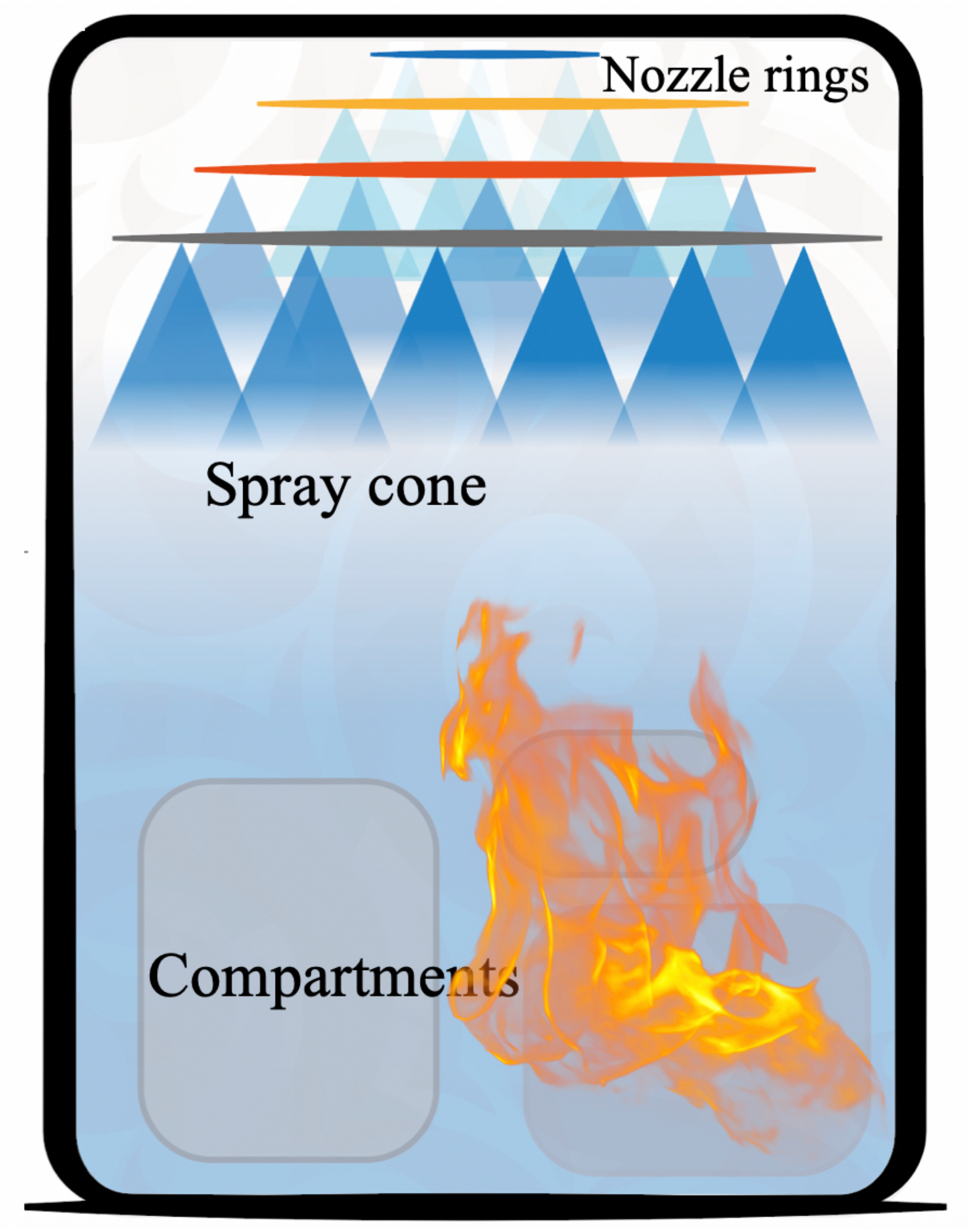
Figure 1. A sketch of the spray system for fire mitigation in an industrial building.
Energies 14 01135 g001
Figure 2. (a) Ramp bottom nozzle and its section view [41]; (b) hollow cone spray with fine droplets. h, the vertical distance from the nozzle; R, the radial distance from the spray central line; O, the numerical injection plane.
Energies 14 01135 g002
Figure 3. Geometry and mesh grid of a single spray nozzle: (a) a sketch of the geometry and spray nozzle position; (b) a grid of mean mesh size Δ x = 1.5 cm in the injection zone L i = 1.5 m; L x = 3.5 m, L y = 3 m, and L z = 3.5 m; with O the numerical injection plane; symmetric and wall boundary conditions highlighted.
Energies 14 01135 g003
Figure 4. Mesh convergence of different flow parameters as a function of the radial distance from the center R at plane h = 60 cm; results of the mean mesh size Δ x = 2.5 cm ( Energies 14 01135 i001), Δ x = 1.67 cm ( Energies 14 01135 i002), Δ x = 1.25 cm ( Energies 14 01135 i003), Δ x = 1.11 cm ( Energies 14 01135 i004), and Δ x = 0.67 cm ( Energies 14 01135 i005); (a) turbulence kinetic energy k, (b) axial gas velocity u g , z , and (c) the mesh convergence tendency for k m a x as a function of mean mesh size Δ x at plane h = 60 cm ( Energies 14 01135 i006).
Energies 14 01135 g004
Figure 5. Time convergence of the axial gas velocity u g , z and the turbulent kinetic energy k ( m 2 / s 2 ), with Δ x = 1.5 cm, Δ t = 1 ms: Position 1 ( h = 0.5 m) ( Energies 14 01135 i007), Position 2 ( h = 1.5 m) ( Energies 14 01135 i008), and Position 3 ( h = 2.3 m) ( Energies 14 01135 i009); (a) vertical gas velocity and (b) turbulent kinetic energy as a function of time.
Energies 14 01135 g005
Figure 6. Validation of the droplet velocity at different vertical positions as a function of the radial distance from the center R for a monodisperse spray; (a) axial velocity v d , z and (b) radial velocity v d , r . Experimental measurements at h = 20 cm, ( Energies 14 01135 i010), h = 40 cm ( Energies 14 01135 i011), h = 60 cm ( Energies 14 01135 i012), h = 95 cm ( Energies 14 01135 i013); numerical simulation of [21] at h = 20 cm ( Energies 14 01135 i014), h = 40 cm ( Energies 14 01135 i015), h = 60 cm ( Energies 14 01135 i016), h = 95 cm ( Energies 14 01135 i017); current simulation at h = 20 cm ( Energies 14 01135 i001), h = 40 cm ( Energies 14 01135 i002), h = 60 cm ( Energies 14 01135 i003), h = 95 cm ( Energies 14 01135 i005).
Energies 14 01135 g006
Figure 7. Validation of the droplet velocity at different vertical positions as a function of the radial distance from the center R for a polydisperse spray; (a) mean axial velocity v ¯ d , z and (b) mean radial velocity v ¯ d , r . Experimental measurements at h = 20 cm, ( Energies 14 01135 i010), h = 40 cm ( Energies 14 01135 i011), h = 60 cm ( Energies 14 01135 i012), h = 95 cm ( Energies 14 01135 i013); Numerical simulation of [21] at h = 20 cm ( Energies 14 01135 i001), h = 40 cm ( Energies 14 01135 i002), h = 60 cm ( Energies 14 01135 i003), h = 95 cm ( Energies 14 01135 i005); current simulation at h = 20 cm ( Energies 14 01135 i001), h = 40 cm ( Energies 14 01135 i002), h = 60 cm ( Energies 14 01135 i003), h = 95 cm ( Energies 14 01135 i005).
Energies 14 01135 g007
Figure 8. Spatial distribution of the properties on XZ plane at y = 0.05 m for a monodisperse spray, t = 10 s, Δ x = 1.5 cm, Δ t = 1 ms; (a) droplet volume fraction α t o t and (b) turbulent kinetic energy k ( m 2 / s 2 ).
Energies 14 01135 g008
Figure 9. Spatial distribution of the properties on XZ plane at y = 0.05 m for a polydisperse spray, t = 10 s, Δ x = 1.5 cm, Δ t = 1 ms; (a) droplet volume fraction α t o t and (b) turbulent kinetic energy k ( m 2 / s 2 ).
Energies 14 01135 g009
Figure 10. (a) Turbulent integral length scale L t (m) on the XZ plane at y = 0.05 m; (b) turbulent kinetic energy k ( m 2 / s 2 ) on the XY plane at h = 1.5 m.
Energies 14 01135 g010
Figure 11. Evolution of normalized volume fraction α d p / α t o t for droplets of different diameters: d p = 166 μm ( Energies 14 01135 i018), d p = 277 μm ( Energies 14 01135 i019), d p = 388 μm ( Energies 14 01135 i020), d p = 500 μm ( Energies 14 01135 i021), d p = 611 μm ( Energies 14 01135 i022), d p = 722 μm ( Energies 14 01135 i023), d p = 833 μm ( Energies 14 01135 i024), d p = 944 μm ( Energies 14 01135 i025); (a) h = 40 cm and (b) h = 95 cm.
Energies 14 01135 g011
Figure 12. Histogram for different droplet diameters at vertical distances from the nozzle h = 20 cm and h = 95 cm; (a) normalized volume fraction α d p / α t o t and (b) normalized number fraction N d p / N t o t .
Energies 14 01135 g012
Figure 13. (a) Evolution of the surface-averaged droplet volume fraction α ¯ as a function of h; monodisperse spray ( Energies 14 01135 i014), polydisperse spray ( Energies 14 01135 i026); (b) Evolution of k m a x at different vertical surfaces as a function of the vertical distance; monodisperse spray ( Energies 14 01135 i027), polydisperse spray ( Energies 14 01135 i028).
Energies 14 01135 g013
Figure 14. (a) Geometry and (b) mesh of the two spray nozzles Δ x = 2 cm; L i = 3 m, L x = 7 m, L y = 3 m, and L z = 3.5 m with O the numerical injection plane; symmetric and wall boundary conditions highlighted in (a).
Energies 14 01135 g014
Figure 15. Properties on the XZ plane at 30 s; (a) droplet volume fraction α t o t , (b) integral length scale L t (m), (c) turbulent kinetic energy k ( m 2 / s 2 ), and (d) turbulent dissipation rate ε ( m 2 / s 3 ).
Energies 14 01135 g015
Figure 16. Evolutions of the droplet volume fraction α t o t (a) and the turbulent kinetic energy k ( m 2 / s 2 ) (b) on the XY plane y = 0.05 m as a function of x, h = 0.2 m ( Energies 14 01135 i029), h = 0.5 m ( Energies 14 01135 i030), h = 1.0 m ( Energies 14 01135 i031), and h = 1.5 m ( Energies 14 01135 i031).
Energies 14 01135 g016
Figure 17. (a) Evolution of the surface averaged droplet volume fraction α ¯ as a function of h: tow nozzles ( Energies 14 01135 i032) and single nozzle ( Energies 14 01135 i033); (b) evolution of k m a x as a function of the vertical distance h: two nozzles ( Energies 14 01135 i034) and single nozzle ( Energies 14 01135 i035).
Energies 14 01135 g017
Table 1. Particles with different diameters in the polydisperse spray [21].
Particle ClassDiameter (m)
155
2166
3277
4388
5500
6611
7722
8833
9944
Publisher’s Note: MDPI stays neutral with regard to jurisdictional claims in published maps and institutional affiliations.