
Selective Water Plugging Technology for Horizontal Well with Screen Completion

Abstract
:
1. Introduction
2. Development and Performance Evaluation of Selective Water Plugging System
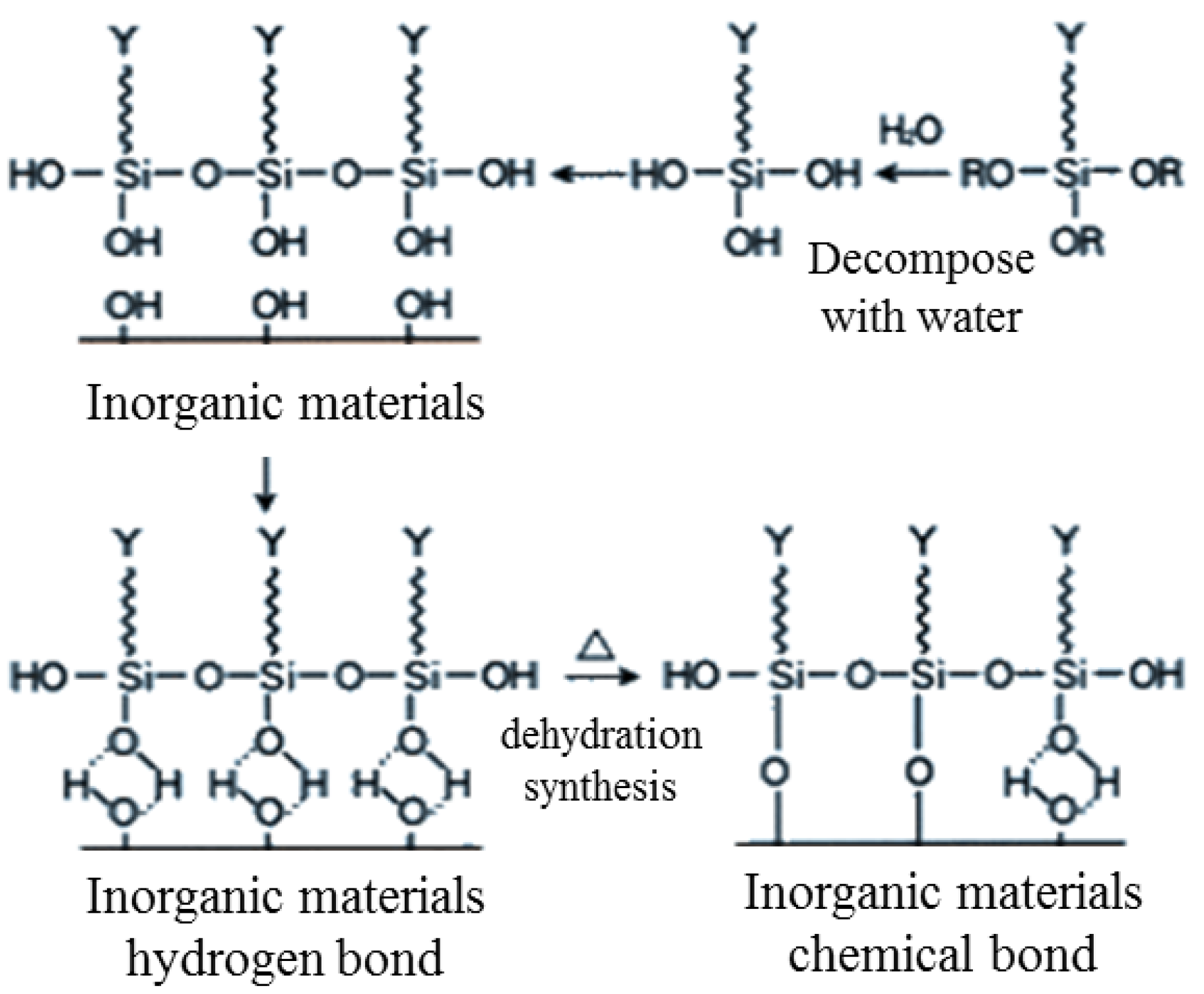
2.1. Water Plugging Mechanism
2.2. Selectivity Evaluation Experiment of Plugging Agent
2.2.1. Evaluation of SD107 Gelling Selectivity
- (1)
- Experimental materials
- (2)
- Experimental process
- (3)
- Experimental results
2.2.2. Evaluation of SD107 Gel Blocking Selectivity
- (1)
- Selection of experimental materials and formulas
- (2)
- Experimental method
- (3)
- Experimental results
2.2.3. Evaluation of SD107 Gel Blocking Effect
- (1)
- Selection of experimental materials and formulas
- (2)
- Experimental methods and procedures
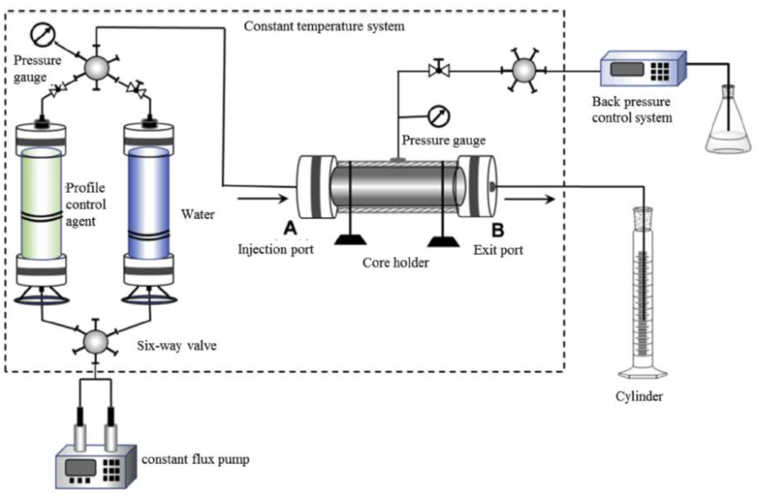
- Experiments were carried out with simulated oil displacement equipment and supporting facilities (Petroleum Scientific Research Instrument Co., Ltd., Haian County, China), and nine sets of sand-filled core model tubes with low permeability (size: length 50 cm, diameter 2.5 cm) were made. As per the permeability requirements, the permeability of 1.0 μm2 and 3.0 μm2 was designed, according to the mass ratio of 80–100 mesh:100–120 mesh:160–200 mesh = 2:2:1 to fill 1.0 μm2; according to 80–100 mesh:100–120 mesh:160–200 mesh = 3:1.5:0.5 mass ratio of sand filled 3.0 μm2, after mixing uniformly, fill the core tube model according to a certain degree of compaction.
- The dry weight of the core was measured as m1, the saturated formation water was evacuated, the wet weight was measured as m2, the pore volume was measured (v = (m2–m1)/p water), and the porosity was calculated.
- The pipelines were connected in accordance with the experimental procedure and the water permeability was measured. The pressure change range of 30 min was less than 5% or unchanged, and the permeability was calculated as per Darcy’s law.
- At a constant temperature of 55 °C, the high and low permeability cores were saturated with oil, respectively, and the saturated oil was stopped when the outlet oil content was greater than 98%.
- The high and low permeability cores were connected in parallel and the water flood tests was carried out, and the water flood tests were stopped when the comprehensive water cut reached 98%.
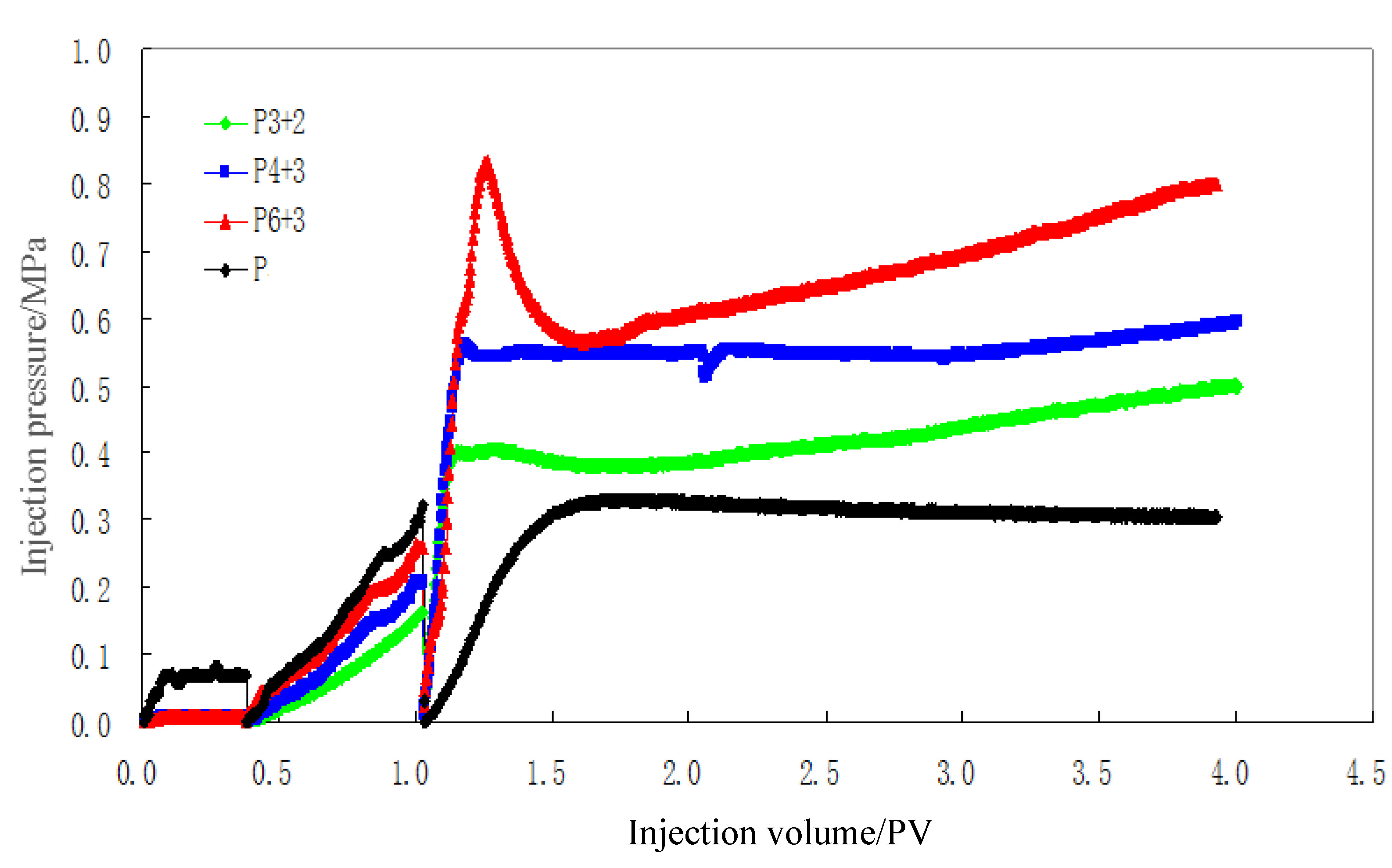
- On nine sets of parallel cores, plugged the high-permeability cores, and injected the plugging agent system 0.1, 0.2, 0.3, 0.4, 0.5, 0.6, 0.7, 0.8 and 1.0 times the volume of the high-permeability cores, and kept the temperature at 5 °C for 48 h.
- After the constant temperature process, the resistances of the high- and low-permeability cores were tested, respectively. After the test, the high- and low-permeability cores were connected in parallel for the subsequent water flood experiments, and the water flood experiments were stopped until the comprehensive water cut reaches 98%.
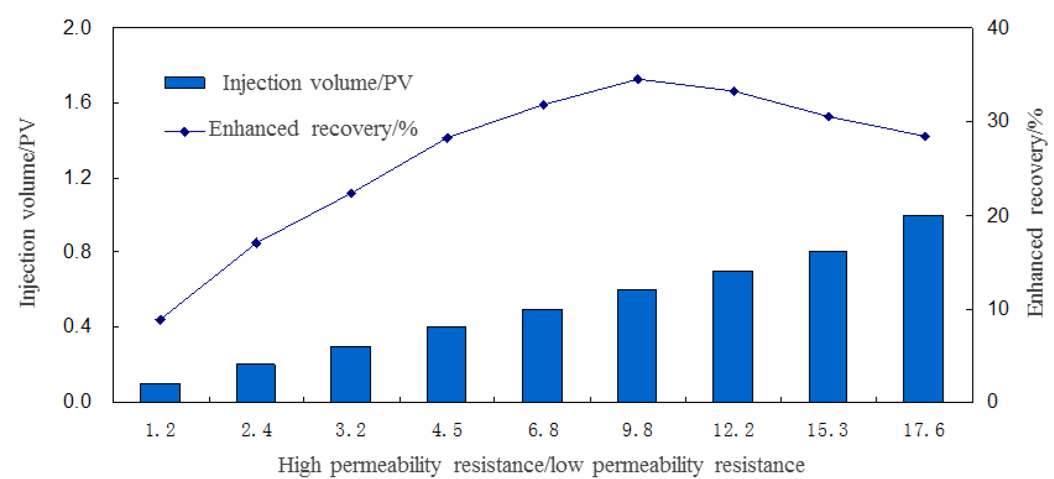
- After the entire process of the displacement experiment and the high-permeability plugging, the relationship between the ratio of resistance to the flow of high-permeability and low-permeability cores and enhanced oil recovery was analyzed.
- (3)
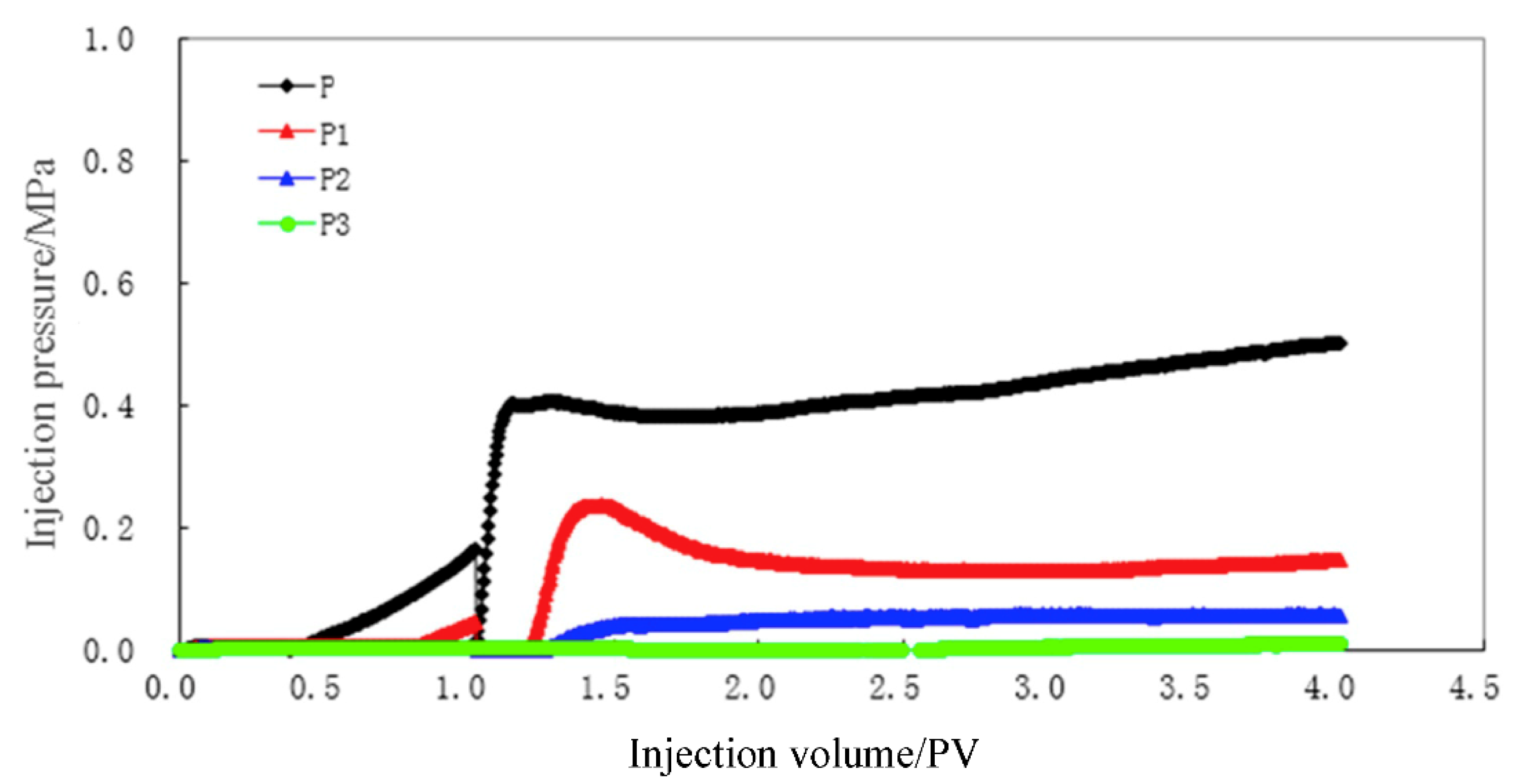
- Experimental results
3. Determination of Key Parameters of Water Plugging in Horizontal Wells
3.1. Calculation of Seepage Resistance of Oil-Water Seepage Channels
3.2. Prediction of Water Plugging Depth of Horizontal Wells
3.3. Calculation of Water Plugging Consumption for Horizontal Wells
4. Field Application
4.1. Production Dynamics and Effluent Analysis
4.2. Water Blocking Test
5. Conclusions
- (1)
- The main composition of the SD107 jelly system developed is: polymer concentration 0.30~0.50% + cross-linking agent concentration 0.30~0.40% + enhancer concentration 0.25~0.35%; the system has good oil-water selectivity Glue and oil-water selective plugging properties; the enhanced oil recovery rate is highest when the high–low permeability core resistance ratio after plugging is about 10.0.
- (2)
- On the basis of the equivalent seepage resistance method, the resistance of the oil section, the resistance of the high water cut section, and the resistance of the water outlet section after plugging are calculated, which are the horizontal well water plugging process parameters (plugging depth, plugging agent strength, plugging agent dosage, combination mode, and on-site injection pressure control, etc.) design provides a basis for improving the pertinence and theory of horizontal well water plugging design.
- (3)
- Results of the field test indicate that the daily fluid production before water plugging is 20.4 t/d, the daily oil production is 4.9 t/d, the water content is 76.0%, the daily fluid production after water plugging is 27.3 t/d, and the daily oil production is 20.4 t/d, Water cut is 25.3/%; daily oil increase is 15.5 t/d, water cut is reduced by 50.7%, a good water plugging effect is seen, and a new successful model for water plugging of horizontal wells with slotted screens of the same type has been established.
- (4)
- The selection of a good oil-water phase selective plugging agent and accurate water plugging process parameter calculation method established a new model and successful experience for water plugging in horizontal wells with slotted screens of the same type, and improved the pertinence and theory of horizontal well water plugging technology.
Author Contributions
Funding
Institutional Review Board Statement
Informed Consent Statement
Data Availability Statement
Acknowledgments
Conflicts of Interest
Nomenclature
| R0 | the resistance of the oil outlet section, Pa/(cm3/s) |
| µ0 | viscosity of underground crude oil, mPa·s |
| µgel | viscosity of the gel, mPa·s |
| µw | viscosity of oil-water mixture in water channel, mPa·s |
| K | the average permeability of the formation, μm2 |
| h0 | length of oil outlet section, cm |
| Rw | resistance of the outlet section, Pa/(cm3/s) |
| hw | length of outlet section, cm |
| re | liquid supply radius, cm |
| rw | wellbore radius, cm |
| Rff | residual resistance coefficient of jelly |
| re1 | blocking range of plugging agent, cm |
| Q | production, m3/d |
| ∆P | production pressure difference, Pa |
| R | section resistance, Pa/(cm3/s) |
| R | resistance, Pa/(cm3/s) |
| Qp | the amount of plugging agent, m3 |
| c | correction factor |
| L | the length of plugging section, m |
| Φ | effective porosity |
References
- Yikun, L.; Pin, H.; Jihua, F.; Daiyu, Z. The background, current situation and development trend of water plugging in horizontal wells. J. Oil Gas Technol. 2005, 27, 757–760. [Google Scholar]
- Falin, W.; Yuzhang, L.; Yikun, L.; Xiaofen, T.; Chunming, X. Current status and development trend of water plugging technology in horizontal wells with slotted liners. Pet. Drill. Prod. Technol. 2007, 29, 40–43. [Google Scholar]
- Hongjiang, G.; Jingfeng, G.; Qiling, L.; Xijun, L. Research on chemical water plugging supporting agents for horizontal wells. Oilfield Chem. 2009, 26, 387–390. [Google Scholar]
- Jiasheng, L. Improvement and test of water plugging technology for horizontal wells in heavy oil reservoirs with edge and bottom water. Mod. Chem. Ind. 2013, 42, 290–293. [Google Scholar]
- Wei, L.; Pingping, Q.; Yefei, W. Research on inorganic precipitates as water plugging and profile control agents. Inorg. Salt Ind. 2007, 39, 41–43. [Google Scholar]
- Guangyan, L.; Fei, Q.; Wenming, W.; Liang, L.; Zhaowen, Z. Water production analysis and supporting water plugging technology for horizontal wells in Tahe sandstone reservoir. Fault Block Oil Gas Field 2013, 20, 248–251. [Google Scholar]
- Ghosh, B.; Bemani, A.S.; Wahaibi, Y.M.; Hadrami, H.; Boukadi, F.H. Development of a novel chemical water shut-off method for fractured reservoirs: Laboratory development and verification through core flow experiments. J. Pet. Sci. Eng. 2011, 96, 176–184. [Google Scholar] [CrossRef]
- Kadyrov, R.R.; Nizaev, R.K.; Yartiev, A.F.; Mukhametshin, V.V. A novel water shut-off technique for horizontal wells at fields with hard-to-recover oil reserves. Neftyanoe Khozyaistvo 2017, 5, 44–47. [Google Scholar] [CrossRef]
- Zaripov, A.T.; Beregovoi, A.N.; Shaikhutdinov, D.K.; Khafizov, R.I.; Zakharov, Y.V.; Bisenova, A.A. Improving the Efficiency of Steam-Assisted Heavy Oil Production Using Gel-Forming Systems. Tekhnologii Nefti I Gaza 2018, 1, 35–38. [Google Scholar]
- Czarnota, R.; Stopa, J.; Janiga, D.; Kosowski, P.; Wojnarowski, P. Semianalytical horizontal well length optimization under pseudosteady-state conditions. In Proceedings of the 2018 2nd International Conference on Smart Grid and Smart Cities (ICSGSC), Kuala Lumpur, Malaysia, 12–14 August 2018. [Google Scholar]
- Ghahri, P.; Jamiolahmadi, M.; Alatefi, E.; Wilkinson, D.; Dehkordi, F.S.; Hamidi, H. A new and simple model for the prediction of horizontal well productivity in gas condensate reservoirs. Fuel 2018, 223, 431–450. [Google Scholar] [CrossRef] [Green Version]
- Fang, Y.J.; Yang, E.L.; Cui, X.N. Study on profile control and water shut-off performance of interpenetrating network polymer gel composite system in shallow low temperature fractured oil layer. Chem. Sel. 2019, 4, 27. [Google Scholar] [CrossRef]
- Chen, X.C.; Feng, Q.H.; Wang, Q. Performance prediction of gel water shutoff in horizontal wells using a newly coupled reservoir-wellbore model. J. Energy. Resour. ASME 2014, 136, 2. [Google Scholar]
- Fulin, Z.; Dong, C.; Jinfu, Z. Alkaline silica gel water plugging agent. J. Univ. Pet. Ed. Nat. Sci. 1988, 12, 1–9. [Google Scholar]
- Zhenwei, G. Water plugging in horizontal wells in bottom water sandstone reservoirs in Tahe Oilfield to enhance oil recovery. Fault Block Oil Gas Field 2010, 17, 372–375. [Google Scholar]
- Makkia, A.; Redhah, S.A.; Saleh, A.; Saeed, S. Rigless Water Shut-Off Experience in Offshore Saudi Arabia; SPE: Dubai, United Arab Emirates, 2003; p. 81443. [Google Scholar]
- Davarpanah, A.; Mirshekari, B. Mathematical modeling of injectivity damage with oil droplets in the waste produced water re-injection of the linear flow. Eur. Phys. J. Plus 2019, 134, 180–187. [Google Scholar] [CrossRef]
- Uddin, S.; Jimmy, D.; Dolan, R.A. Lessons Learned from the First Open Hole Horizontal Well Shutoff Job Using Two New Polymer Systems—A Case History from Wafra Ratawi Field; SPE: Dubai, United Arab Emirates, 2003; p. 81447. [Google Scholar]
- Hu, X.; Xie, J.; Cai, W.; Wang, R.; Davarpanah, A. Thermodynamic effects of cycling carbon dioxide injectivity in shale reservoirs. J. Pet. Sci. Eng. 2020, 195, 107717. [Google Scholar] [CrossRef]
- Caili, D.; Fulin, Z.; Yaolin, L.; Decheng, F.; Shang, R. Water ridge advance control technology of horizontal wells in offshore oilfields. Acta Pet. Sin. 2005, 26, 69–72. [Google Scholar]
- Zaitoun, A.; Kohler, N.; Montemurro, M.A. Control of Water Influx in Heavy-Oil Horizontal Wells by Polymer Treatment; SPE: Sunnyvale, CA, USA, 1992; p. 24611. [Google Scholar]
- Lovel Land, K.R.; Bond, A.J. Recent Application of Coiled Tubing in Remedial Well Work at Prude Bay; SPE: Sunnyvale, CA, USA, 1996; p. 35587. [Google Scholar]
- Hu, X.; Li, M.; Peng, C.; Davarpanah, A. Hybrid thermal-chemical enhanced oil recovery methods; An experimental study for tight reservoirs. Symmetry 2020, 12, 947. [Google Scholar] [CrossRef]
- Arangth, R.; Mkpasi, E.E. Water Shut-Off Treatments in Open Hole Horizontal Wells Completed with Slotted Liners; SPE: Sunnyvale, CA, USA, 2002; p. 74806. [Google Scholar]
- Nesic, S.; Zolotukhin, A.; Mitrovic, V.; Govedarica, D.; Davarpanah, A. An analytical model to predict the effects of suspended solids in injected water on the oil displacement efficiency during waterflooding. Processes 2020, 8, 659. [Google Scholar]
- Davarpanah, A.; Mirshekari, B. A simulation study to control the oil production rate of oil-rim reservoir under different injectivity scenarios. Energy Rep. 2018, 4, 664–670. [Google Scholar] [CrossRef]
- Davarpanah, A. Parametric study of polymer-nanoparticles-assisted injectivity performance for axisymmetric two-phase flow in EOR processes. Nanomaterials 2020, 10, 1818. [Google Scholar] [CrossRef] [PubMed]
- Wojnarowski, P.; Czarnota, R.; Janiga, D.; Stopa, J. Novel liquid-gas corrected permeability correlation for dolomite formation. Int. J. Rock Mech. Min. Sci. 2018, 112, 11–15. [Google Scholar] [CrossRef]
- Jun, Y.; Jianwei, G.; Aimin, L. Principles and Methods of Reservoir Engineering; University of Petroleum Press: Dongying, China, 2000. [Google Scholar]


| Number | Polymer Concentration/% | Cross-linking Agent Concentration/% | Enhancer Concentration/% |
|---|---|---|---|
| 1 | 0.3 | 0.2 | 0.25 |
| 2 | 0.4 | 0.3 | 0.3 |
| 3 | 0.6 | 0.3 | 0.35 |
| Medium Types | Jelly Formula/% | System Viscosity/mPa·s | Steady Pressure/MPa | Core Permeability/μm2 | Permeability of Subsequent Flooding 2 PV/μm2 | Follow-Up Drive 2 PV Blocking Rate/% | Follow-Up Drive 2 PV Residual Resistance |
|---|---|---|---|---|---|---|---|
| Water phase | 0.3 + 0.2 + 0.25 | 140 | 0.00675 | 2.514 | 0.0440 | 98.25 | 57.19 |
| 0.4 + 0.3 + 0.30 | 380 | 0.0075 | 2.263 | 0.0309 | 98.64 | 73.33 | |
| 0.6 + 0.3 + 0.35 | 980 | 0.0075 | 2.263 | 0.0278 | 98.77 | 81.47 | |
| Oil phase | 0.6 + 0.3 + 0.35 | 980 | 0.072 | 2.628 | 0.5900 | 77.55 | 4.45 |
| Parameter | Value | Parameter | Value |
|---|---|---|---|
| Underground crude oil viscosity/mPa·s | 800 | Residual drag coefficient | 15 |
| Length of oil outlet section/cm | 5000 | Water channel mixture viscosity/mPa·s | 120 |
| Liquid supply radius/cm | 25,000 | Gel viscosity/mPa·s | 200 |
| Wellbore radius/cm | 5 | Average permeability of formation/μm2 | 2.1 |
| Porosity/% | 35 | Length of oil outlet section/cm | 1000 |
Publisher’s Note: MDPI stays neutral with regard to jurisdictional claims in published maps and institutional affiliations. |
© 2021 by the authors. Licensee MDPI, Basel, Switzerland. This article is an open access article distributed under the terms and conditions of the Creative Commons Attribution (CC BY) license (http://creativecommons.org/licenses/by/4.0/).
Share and Cite
Deng, B.; Jia, Z.; Liu, W.; Liu, X.; Gu, J.; Ye, W.; Wen, H.; Qu, Z. Selective Water Plugging Technology for Horizontal Well with Screen Completion. Energies 2021, 14, 791. https://doi.org/10.3390/en14040791
Deng B, Jia Z, Liu W, Liu X, Gu J, Ye W, Wen H, Qu Z. Selective Water Plugging Technology for Horizontal Well with Screen Completion. Energies. 2021; 14(4):791. https://doi.org/10.3390/en14040791
Chicago/Turabian StyleDeng, Bo, Zhiwei Jia, Wei Liu, Xiaoqiang Liu, Jianwei Gu, Weibao Ye, Hongbin Wen, and Zhanqing Qu. 2021. "Selective Water Plugging Technology for Horizontal Well with Screen Completion" Energies 14, no. 4: 791. https://doi.org/10.3390/en14040791