Article

Model-Free Control Using Improved Smoothing Extended State Observer and Super-Twisting Nonlinear Sliding Mode Control for PMSM Drives

1
College of Electrical Engineering and Control Science, Nanjing Tech University, Nanjing 211899, China
2
College of Electrical Engineering, Tongling University, Tongling 244061, China
*
Author to whom correspondence should be addressed.
Energies 2021, 14(4), 922; https://doi.org/10.3390/en14040922
Submission received: 4 January 2021 / Revised: 2 February 2021 / Accepted: 5 February 2021 / Published: 9 February 2021

Abstract

:
This paper proposes a novel model-free super-twisting nonlinear sliding mode control (MFSTNLSMC) strategy with an improved smoothing extended state observer (SESO) for permanent magnet synchronous motor (PMSM) drives. First of all, the improved SESO is introduced to estimate the unknown term of the PMSM ultra-local model. Secondly, a novel nonlinear sliding mode surface (NLSMS) is designed, which can effectively overcome the disadvantages of simple and rough signal processing of the conventional linear sliding mode surface. At the same time, a super-twisting (ST) structure is chosen to suppress the chattering phenomenon and improve system robustness. Then, the Lyapunov stability theorem is used to prove the stability of the proposed control algorithm. Finally, both comparative simulations and experimental demonstrations verify the excellent speed tracking performance and robustness of the proposed control strategy.

1. Introduction

As the permanent magnet synchronous motor (PMSM) has low energy consumption, reliable operation, and simple structure, it has been widely used in coal conveyor systems [1], mine traction electric locomotives [2], electric vehicles [3,4], water pumping applications [5] and so on. However, the PMSM dynamic model has the characteristics of coupling and is multivariable. It is difficult for the traditional model-based control strategy to meet the control requirements.
Han proposed a nonlinear extended state observer (ESO) [6]. Because of its simple structure and high estimation efficiency, the nonlinear ESO has been widely used in many applications such as welding robot [7], linear system with incipient fault [8], aerial inertially stabilized platform [9], teleoperated robotic system [10] and so on. The sliding mode controller (SMC) strategy has become an important research branch in the field of automatic control. During the past few decades, various SMC strategies have been widely used in the PMSM speed control system such as fractional order SMC [11,12], integral SMC [13], fuzzy SMC [14,15], high-order SMC [16] and non-singular terminal SMC [17]. As a high-order SMC algorithm, the super-twisting (ST) structure has been widely studied by many scholars. In a Sami et al. paper [18], a ST switching control law was designed for a doubly fed induction generator. In a Wang et al. paper [19], a ST switching control law was designed for a cable-driven manipulator. In another research [20], a ST switching was used for a three-phase grid-connected photovoltaic system.
Reference [21] proposed a model free sliding mode control (MFSMC) strategy, which integrating model free control theory, intelligent proportional integral (iPI) controller, SMC strategy, and an observer. The tracking error can be brought to zero by the MFSMC strategy without the mathematical model of the controlled object. Because of its simple structure, strong robustness, and strong practicability, the MFSMC strategy is widely used in doubly fed induction generator wind turbine systems [21], active vehicle suspension systems [22], laboratory twin rotor aerodynamic systems [23], quadrotor helicopters [24], and so on. The design of the MFSMC strategy is usually divided into two parts. The first part is mainly composed of an iPI controller and an observer, the second part is mainly composed of the equivalent controller and switching controller of the SMC strategy.
Considering the previous research, an improved smoothing extended state observer (SESO) and a novel model-free super-twisting nonlinear sliding mode control (MFSTNLSMC) strategy for the PMSM speed servo system are proposed in this paper. The proposed control strategy is based on the ultra-local model of the PMSM, which is independent of the exact mathematical model of the controlled object. Firstly, an improved SESO is proposed to estimate the unknown terms of the ultra-local model while overcoming the flutter phenomenon caused by the traditional ESO. Secondly, a novel nonlinear sliding mode surface (NLSMS) is designed, which can effectively overcome the disadvantages of simple and rough signal processing of the conventional linear sliding mode surface. Finally, the proposed MFSTNLSMC strategy is designed by the novel NLSMS and a ST approaching law.
To sum up, through comparisons with the existing studies, three contributions of this article are highlighted as:
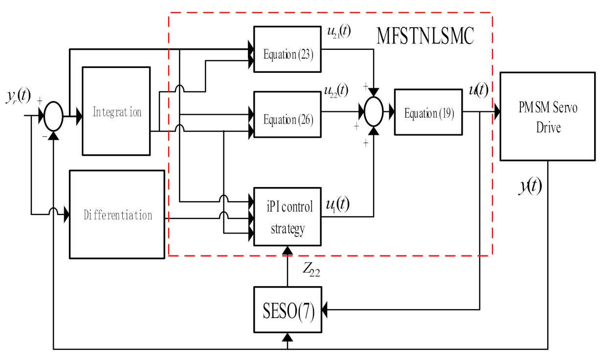
  • This paper is the first to propose a novel MFSTNLSMC strategy that integrates the ST approaching law, the novel NLSMS and the MFC strategy. The particular emphasis here is that the proposed MFSTNLSMC strategy does not require the detailed mathematical models of PMSM.
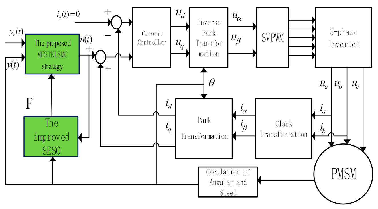
  • An improved SESO is proposed to estimate the unknown terms, which is based on the novel MFSTNLSMC strategy proposed for the PMSM speed servo system.
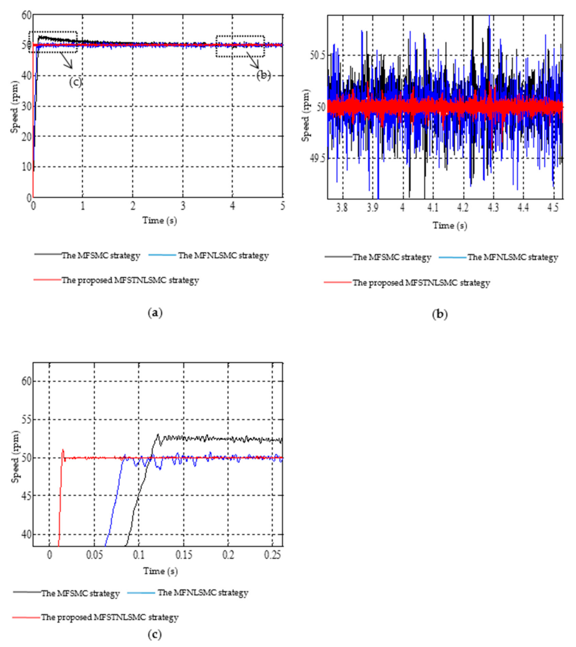
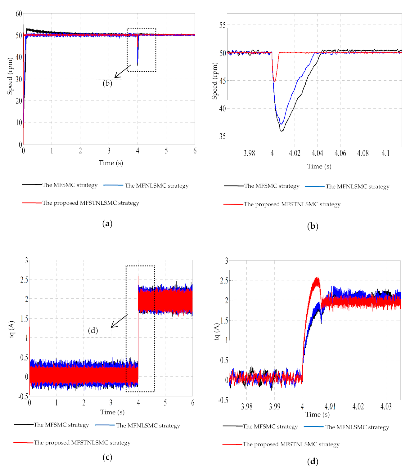
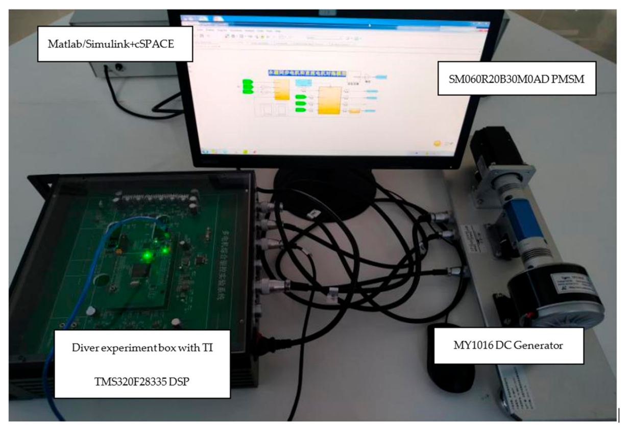
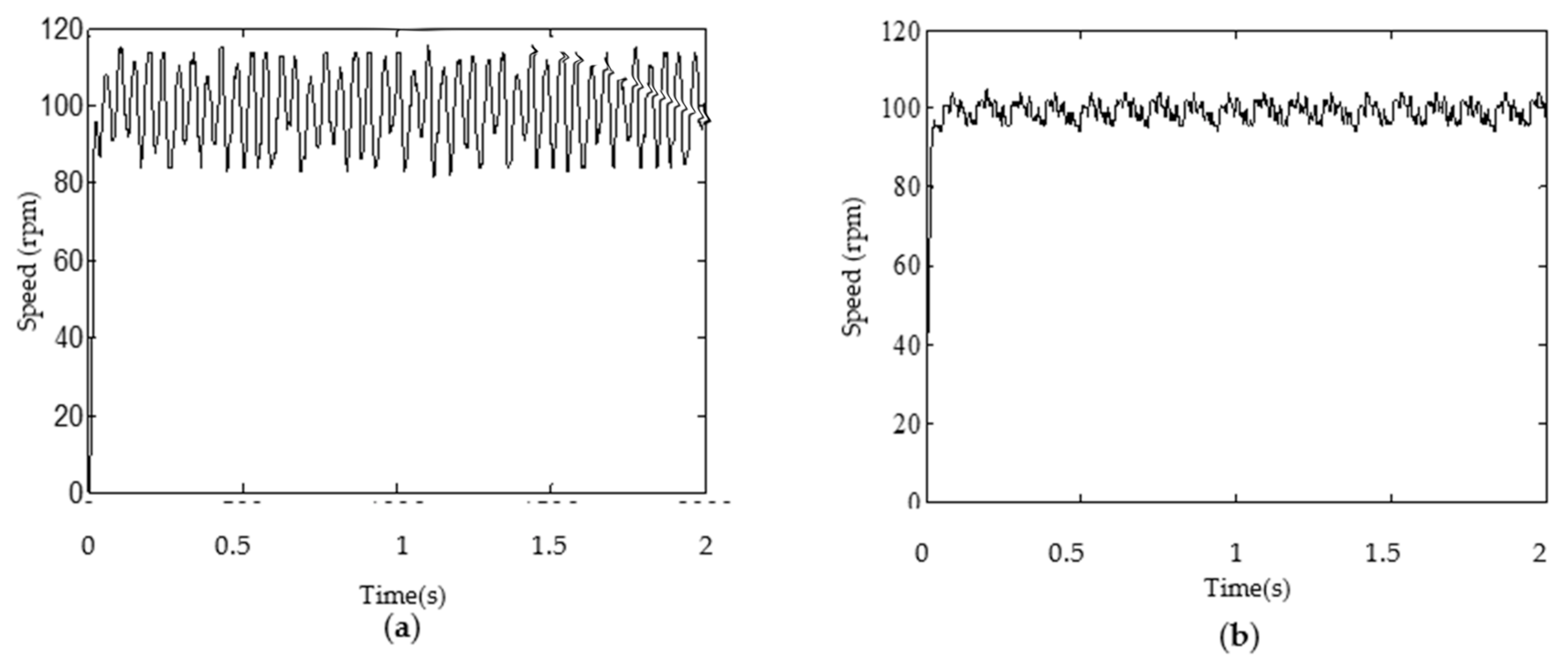
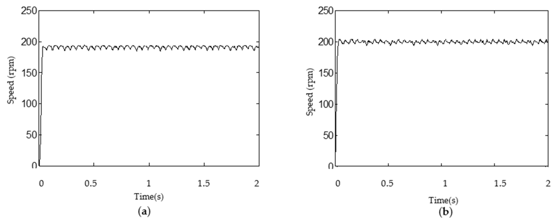
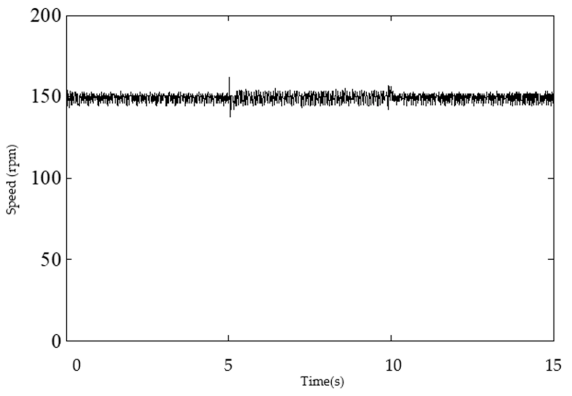
  • The effectiveness of the proposed control strategy is proved by the comparative simulations and experimental demonstrations.
Furthermore, this paper is organized as:
In Section 2, the ultra-local model of PMSM is briefly presented. Section 3 deduces the improved SESO and the novel MFSTNLSMC strategy. In the next Section, the comparative simulations and experimental demonstrations are given. Finally, Section 5 addresses conclusions and future work.

2. Problem Formulation

The mechanical torque equation and dynamic equation of PMSM are expressed in (1) and (2), respectively. The linear ultra-local model of the PMSM is expressed in (3) and the system track error is denoted in (4) [25,26,27].
T e T L = J ω ˙ + B ω T e = 1.5 p n φ f i q
ω ˙ = 3 p n φ f 2 J i q B J ω 1 J T L
y ˙ = a u + F
e = y r y
where  T e  and  T L  is the electromagnetic torque and load torque, respectively; φ f  is the flux linkage;  p n  is the pole pairs; i q  is the q-armature current; ω  is the mechanical rotor angular speed; B is the damping coefficient;  J  is the rotational inertia; y  is the output of the ultra-local model; u  is the ultra-local model input; a  is the input parameter, which should be therefore clear that its numerical value and is obtained by trials and errors; F  is the unknown term of the linear ultra-local model, which contains uncertain values due to the damping coefficient and the load torque; y r  and  e  is the desired output and tracking error, respectively.

3. Main Results

This section proposes a novel model free control strategy using an improved SESO and a MFSTNLSMC strategy for the PMSM speed servo system. Figure 1 shows the novel PMSM speed servo system using the novel model free control strategy. As illustrated in Figure 1, the d-armature current is set to zero.

3.1. Design of Improved SESO

Define  x 1 = y and  x 2 = F , the ultra-local model of PMSM (3) can be described as:
x ˙ 1 = x 2 + a u x ˙ 2 = ϑ
where the differential result of x 2 is ϑ .
Define:
e 1 = Z 21 x 1 e 2 = Z 22 x 2
In this paper, the improved SESO with the following expression is designed as:
Z ˙ 21 = Z 22 β 1 e 1 + b 0 u Z ˙ 22 = β 2 ξ e 1 , θ
where
ξ e 1 , θ = θ e 1 > θ 1 θ e 1 2 + 2 e 1 θ e 1 0 1 θ e 1 2 + 2 e 1 0 > e 1 θ θ e 1 < θ
where  β 1 and  β 2 are the designed positive parameters of the observer; Z 21  and  Z 22  are the estimations of the output and the unknown term, respectively; b 0 = a . Reference [28] gave a detailed description of the smoothing function ξ e 1 , θ .

3.2. Design of the Proposed MFSTNLSMC Strategy

The conventional linear sliding mode surface with the following expression is shown as [29,30]:
s 1 = η 1 e + η 2 e ,
where  η 1 > 0  and  η 2 > 0 .
Definition 1.
Together with the SESO, the conventional model-free Sliding Mode Control (MFSMC) strategy is designed as:
u = u 1 + u 2 = 1 a K p e + K i e + y ˙ r Z 22 + u 2 u 2 = u 21 + u 22
where  K p R + K i R + ; u 1  and  u 2  are the iPI control strategy and the conventional MFSMC strategy, respectively.
According to [31], the equivalent control can be obtained as:
u 21 = 1 a K p e K i e + η 2 η 1 a e
The following conventional switching control is usually chosen as:
u 22 = 1 a η s i g n s 1
s i g n s 1 = 1 s 1 > 0 0 s 1 = 0 1 s 1 < 0
In this paper, the following novel nonlinear Sliding Mode surface (NLSMS) is proposed as:
s 2 = η 1 s i g e α ^ + η 1 s i g e α ^
s i g e α ^ = e α ^ s i g n e
where  η 1 > 0 , η 2 > 0 and 0 < α ^ < 1 .
When  s 2 = 0 , (14) can be written as:
η 1 e α ^ s i g n e + η 2 e α ^ s i g n e = 0
Let  X = e α ^ s i g n e , (16) can be rewritten as:
X + η 2 η 1 X = 0
Then
X = X ˜ exp η 2 η 1 t
where X ˜ is the coefficients determined by the initial condition.
According to (18), we can get  e 0  when  t , so the stability of the system (16) can be guaranteed.
Definition 2.
Together with the SESO, a model-free nonlinear Sliding Mode Control (MFNLSMC) strategy and the proposed MFSTNLSMC strategy are designed in the following format.
u = u 1 + u 2 = 1 a K p e + K i e + y ˙ r Z 22 + u 2 u 2 = u 21 + u 22
where  u 2 , u 21  and  u 22  can be obtained through the following process.
According to (3), (4) and (19), we can get:
e ˙ + a u 2 + K p e + K i e + Δ d = 0
where  Δ d  is the error of the observation.
Taking derivative of (14), it can be obtained that:
s ˙ 2 = η 1 α ^ e α ^ 1 e ˙ + η 2 s i g e α ^
Substituting (20) in (21), the following equality can be obtained as:
s ˙ 2 = η 1 α ^ e α ^ 1 a u 2 K p e K i e Δ d + η 2 s i g e α ^
According to (22) and ignoring the observation error, the equivalent control can be obtained as:
u 21 = 1 a K p e K i e + η 2 η 1 a α ^ e α ^ 1 s i g e α ^
For the MFNLSMC strategy, the following traditional switching control is chosen as:
u 22 = 1 a η s i g n s 2
For the purpose of eliminating the chattering phenomenon and improving the ability to compensate for disturbances, the following ST scheme is chosen in the proposed MFSTNLSMC strategy [31].
s ˙ 2 = k 1 s 2 1 / 2 s i g n s 2 k 2 s i g n s 2
where  k 1 R + , k 2 R + are scalar constants.
Consequently, the following ST switching control of the proposed MFSTNLSMC strategy is obtained, which is based on the ST scheme (25).
u 22 = 1 a k 1 s 2 1 / 2 s i g n s 2 + k 2 s i g n s 2
The proposed MFSTNLSMC strategy structure diagram is given in Figure 2.

3.3. Stability Analysis

Inspired by the references [32,33,34,35], this section will prove the stability of the proposed MFSTNLSMC strategy and the improved SESO.
According to (6) and (7), the estimation error systems can be given as:
e ˙ 1 = e 2 β 1 e 1 e ˙ 2 = β 2 ξ e 1 , θ ϑ
Define:
e 21 = e 1 e 22 = e 2 β 1 e 1
The derivative of (28) is given by:
e ˙ 21 = e 22 e ˙ 22 = β 1 e 22 β 2 ξ e 21 , θ ϑ
According to [32], the Lyapunov function is designed as:
V 1 = 0 e 21 2 β 2 ξ τ , θ d τ + e 22 2
According to the mean-value theorem for integrals, there exists a  χ 0 , e 21 satisfies the following equation:
V 1 = 0 e 21 2 β 2 ξ τ , θ d τ + e 22 2 = 2 β 2 ξ χ , θ e 21 + e 22 2 > 0
Assumption 1.
The positive gain  β 1 is set such that inequality is satisfied as:
e 22 > ϑ β 1 i f   ϑ > 0 e 22 > ϑ β 1 i f   ϑ < 0
According to Assumption 1, the derivative of (30) is given by as:
V ˙ 1 = 2 e 22 β 2 ξ e 21 , θ + 2 e 22 β 2 ξ e 21 , θ ϑ β 1 e 22 = 2 e 22 β 2 ξ e 21 , θ 2 e 22 β 2 ξ e 21 , θ 2 e 22 ϑ 2 β 1 e 22 2 = 2 e 22 ϑ + β 1 e 22 < 0
In conclusion, V ˙ 1  is a negative definite, which can make  Z 22  converge to the ultra-local model unknown term  F .
In the following paragraphs, the stability of the MFNLSMC strategy and the proposed MFSTNLSMC strategy will be discussed, respectively.
Assumption 2.
The value of Δ d is satisfied as follows:
Δ d < Φ
where Φ is a positive constant.
The Lyapunov function for the MFNLSMC strategy is chosen as:
V 2 = 1 2 s 2 2 > 0
Computing the time derivative of the equation (35), it can be shown as follows:
V ˙ 2 = s 2 s ˙ 2 = s 2 η 1 α ^ e α ^ 1 e ˙ + η 2 s i g e α ^ = s 2 η 1 α ^ e α ^ 1 a u 2 K p e K i e Δ d + η 2 s i g e α ^
According to (23), (24), and (36), we obtain the following equation:
V ˙ 2 = η η 1 α ^ e α ^ 1 s 2 s i g n s 2 s 2 η 1 α ^ e α ^ 1 Δ d
For convenience, we define as:
K ˜ = η 1 α ^ e α ^ 1
We know the value of  K ˜ satisfies the following condition:
K ˜ > 0
Assumption 3.
The value of  η satisfies the following condition:
η > Φ
Actually, according to Assumption 2 and Assumption 3, we can get:
V ˙ 2 = η K ˜ s 2 K ˜ s 2 Δ d η K ˜ s 2 + K ˜ s 2 Δ d < η K ˜ s 2 + K ˜ s 2 Φ < 0
Accordingly, we can easily conclude that s 2 t = 0  can be satisfied. The proof of the MFNLSMC strategy is completed.
In what follows, the stability of the proposed MFSTNLSMC strategy will be discussed.
According to (23), (26), and (36), we obtain the following equation:
s ˙ 2 = K ˜ k 1 s 2 1 / 2 s i g n s 2 K ˜ k 2 s i g n s 2 K ˜ Δ d
The Lyapunov function for the proposed MFSTNLSMC strategy is chosen as:
V 2 = 1 2 s 2 2 > 0
According to (42) and (43), we obtain the following equation:
V ˙ 2 = s ˙ 2 s 2 = K ˜ s 2 k 1 s 2 1 / 2 s i g n s 2 + k 2 s i g n s 2 + Δ d
According to previous studies [33,34,35], when positive parameters k 1 and k 2 are selected as appropriate values, we can get:
k 1 s 2 1 / 2 s i g n s 2 + k 2 s i g n s 2 > Δ d
Then
s 2 k 1 s 2 1 / 2 s i g n s 2 + k 2 s i g n s 2 + Δ d < 0
According to (39) and (46), we can get:
V ˙ 2 = K ˜ s 2 k 1 s 2 1 / 2 s i g n s 2 + k 2 s i g n s 2 + Δ d < 0
As a matter of fact, it can be observed that the proposed control strategy can lead the sliding mode surface (14) to zero. Hereto, the proof is thus completed.

4. Comparative Simulations and Experimental Demonstrations

4.1. Comparative Simulations

In this section, we will use MATLAB (2014a) software to implement the comparative simulations. Table 1 gives the key PMSM parameters used in the simulation. The key parameter of the improved SESO is set as  θ = 1 . The parameters of the MFSMC strategy, the MFNLSMC strategy, and the proposed MFNLSMC strategy are listed in Table 2, Table 3 and Table 4 respectively.
The following comparative simulation is first carried out to display the influence of the smoothing and derivable function. Figure 3 compares the time response curves of the same unknown item value with the improved SESO and the traditional ESO. Figure 3a shows that both the traditional ESO and the improved SESO can estimate the unknown item value well. However, it can be seen obviously from Figure 3b that the improved SESO has a better ability to suppress the high-frequency flutter phenomenon than the traditional ESO.
To compare the various controllers’ performance, the reference speed (50 rpm) and the simulation time (5 s) are initial parameters. Based on different control schemes, the speed response curves of the PMSM with  2   N m and without load starting and stable operation, are compared in Figure 4 and Figure 5, respectively. From Figure 4a and Figure 5a, the adjustment time of the proposed MFSTNLSMC strategy is the shortest, in contrast with the MFSMC strategy and the MFNLSMC strategy. It clearly reveals that the proposed MFSTNLSMC strategy has the optimal transient performance. From Figure 4b and Figure 5b, we also can obviously conclude that it is significant for the proposed MFSTNLSMC strategy to eliminate the chattering phenomenon.
To further check the anti-disturbance performance of the proposed MFSTNLSMC strategy, the external load is changed suddenly, which becomes 2   N m  from 0   N m  at 4 s. As shown in Table 5, the speed perturbation and the speed recovery time of different control strategies due to sudden load change, are compared. Figure 6 shows the speed response contrastive curves and the circuit response curves of the q axis of different control strategies under the sudden load change. It can be seen from Table 5 and Figure 6, the shortest recovery time and the smallest perturbation amplitude are all gotten by the proposed MFSTNLSMC strategy, which indicates that the proposed MFSTNLSMC strategy has stronger robustness.

4.2. Experimental Results

Aimed to further check on the effectiveness of the proposed MFSTNLSMC strategy, a cSPACE (Control signal process and control engineering) based PMSM speed control experimental platform was applied in this paper. The cSPACE experimental platform was produced by Hedong Intelligent Company in Hefei, China. The cSPACE experimental platform of the PMSM drive system consisted of four basic components, which are shown in Figure 7. A SM060R20B30M0AD PMSM, a Matlab/Simulink+cSPACE, a diver experiment box with TI TMS320F28335 DSP, and a MY1016 DC Generator were selected in the experiment. The Matlab/Simulink software is a math software from American Mathworks Company. In order to verify the wider applicability of the proposed control strategy, the motor selected in the experimental verification was different from the motor used in the simulation verification. The key PMSM parameters used in the experiment are listed: rated power is 200   W ; stator inductance is  0.9   m H ; stator resistance is 0.33 Ω ; rated speed is 3000   r p m ; rotational inertia is 0.189   k g m 2 10 4 and flux linkage is  0.175   W b . The sampling time of the speed loop is set to 0.001s, and the switching frequency is 15KHz. A rotary encoder is used to measure the speed variable of the PMSM. The current is detected by the Hall current sensor. The bus voltage is transmitted to the A/D port of the DSP after the voltage is distributed by the resistances to complete the detection.
The key parameters of the MFSMC strategy are listed as follows:  η 1 = 1 ; η 2 = 80 ; η = 10 . The key parameters of the proposed MFSTNLSMC strategy are listed as follows:  η 1 = 1 ; η 2 = 20  and  α ^ = 0.25 . The parameters of the improved SESO are set as θ = 1 .
The experimental speed response curves of tracking the aim speeds (100 rpm and 200 rpm) under the MFSMC strategy and the proposed MFSTNLSMC strategy are shown in Figure 8 and Figure 9, respectively. In Figure 8 and Figure 9, it is clearly shown that the proposed control strategy to acquire that the experimental speed response curves of the PMSM has a better steady state than that of the MFSMC strategy. It is a fact that the proposed control strategy shows the superior kinematics characteristic.
The anti-disturbance ability of the proposed control strategy for the PMSM is shown in Figure 10. In detailing, there are 15 s in the experiment. A sudden load 0.04   N m  is added at 5 s and then the load  0.04   N m  is removed at 10 s. The experimental result can be concluded that the proposed MFSTNLSMC strategy has a strong anti-disturbance ability for load disturbance. It is clear for the proposed control strategy can conveniently suppress external disturbance.
In summary, the experimental demonstrations verify the excellent speed tracking performance and robustness of the proposed MFSTNLSMC strategy.

5. Conclusions and Future Work

In this study, a novel model-free control strategy is proposed for the PMSM speed regulation system, by using an improved SESO and a novel MFSTNLSMC strategy. The improved SESO is designed to overcome the shaking phenomenon caused by the traditional ESO while accurately observing the unknown terms of the system. A novel NLSMS is designed. The proposed MFSTNLSMC strategy is designed by the novel NLSMS and a ST approaching law, which has excellent performance. Both comparative simulations and experimental demonstrations verify the excellent speed tracking performance and robustness of the proposed control strategy. In view of the fact that there is an increasing complexity of the control algorithm due to the multiple parameters of the proposed strategy, we will choose an intelligent optimization algorithm to complete the selection of the multiple parameters in future work.

Author Contributions

This is a joint work and the authors were in charge of their expertise and capability: P.G. for investigation, analysis, and writing; G.Z. for funding support. X.L. for manuscript revision. All authors have read and agreed to the published version of the manuscript.

Funding

This research was supported by the National Natural Science Foundation of China under Grant (no.61703202), by the Natural Science Foundation of Universities of Anhui Province (no. KJ2020A0692), and by the Building Electrical and Intelligent Professional Excellence Engineer Training Innovation Project (no. 2020zyrc153).

Data Availability Statement

Data sharing not applicable.

Acknowledgments

The authors would like to express their gratitude to all those who helped them during the writing of this paper. The authors would like to thank the reviewers for their valuable comments and suggestions.

Conflicts of Interest

The authors declare no conflict of interest.

References

  1. Li, S.; Zhou, X. Sensorless energy conservation control for permanent magnet synchronous motors based on a novel hybrid observer applied in coal conveyer cystems. Energies 2018, 11, 2554. [Google Scholar] [CrossRef] [Green Version]
  2. Yan, J.; Wang, H.; Huang, S.; Lan, Y. Load disturbance observer-based complementary sliding mode control for PMSM of the mine traction electric locomotive. Int. J. Fuzzy Syst. 2019, 21, 1051–1058. [Google Scholar] [CrossRef]
  3. Zhang, Z.; Ma, R.; Wang, L.; Zhang, J. Novel PMSM control for anti-lock braking considering transmission properties of the electric vehicle. IEEE Trans. Veh. Technol. 2018, 67, 10378–10386. [Google Scholar] [CrossRef]
  4. Dhulipati, H.; Mukundan, S.; Li, Z.; Ghosh, E.; Tjong, J.; Kar, N.C. Torque performance enhancement in consequent pole PMSM based on magnet pole shape optimization for direct-drive EV. IEEE Trans. Magn. 2020. [Google Scholar] [CrossRef]
  5. Prabhakaran, K.K.; Karthikeyan, A.; Varsha, S.; Perumal, B.V.; Mishra, S. Standalone single stage PV fed reduced switch inverter based PMSM for water pumping application. IEEE Trans. Ind. Appl. 2020. [Google Scholar] [CrossRef]
  6. Han, J. From PID to active disturbance rejection control. IEEE Trans. Ind. Electron. 2009, 56, 900–906. [Google Scholar] [CrossRef]
  7. Wang, P.C.; Hang, D.F.; Lu, B.C. ESO based sliding mode control for the welding robot with backstepping. Int. J. Control 2020. [Google Scholar] [CrossRef]
  8. Hua, X.X.; Huang, D.; Guo, S.H. Extended state observer based on ADRC of linear system with incipient fault. Int. J. Control Autom. Syst. 2020, 18, 1425–1434. [Google Scholar] [CrossRef]
  9. Zhou, X.; Zhu, J.; Zhao, B. Extended state observer/proportion integration differentiation compound control based on dynamic modelling for an aerial inertially stabilized platform. Int. J. Adv. Robot. Syst. 2017, 14, 1–10. [Google Scholar] [CrossRef]
  10. Hua, C.; Li, J.; Yang, Y.; Guan, X. Extended-state-observer based finite-time synchronization control design of teleoperation with experimental validation. Nonlinear Dyn. 2016, 85, 317–331. [Google Scholar] [CrossRef]
  11. Gao, P.; Lv, X.; Ouyang, H.M.; Mei, L.; Zhang, G.M. A novel model-free intelligent proportional-integral super twisting nonlinear fractional-order sliding mode control of PMSM speed regulation system. Complexity 2020. [Google Scholar] [CrossRef]
  12. Gao, P.; Zhang, G.M.; Ouyang, H.M.; Mei, L. An adaptive super twisting nonlinear fractional order PID sliding mode control of permanent magnet synchronous motor speed regulation system based on extended state observer. IEEE Access 2020, 8, 53498–53510. [Google Scholar] [CrossRef]
  13. Gao, P.; Zhang, G.M.; Lv, X.D. Model-free hybrid control with intelligent proportional integral and super-twisting sliding mode control of PMSM drives. Electronics 2020, 9, 1427. [Google Scholar] [CrossRef]
  14. Mao, W.; Liu, G. Development of an adaptive fuzzy sliding mode trajectory control strategy for two-axis PMSM-driven stage application. Int. J. Fuzzy Syst. 2019, 21, 793–808. [Google Scholar] [CrossRef]
  15. Leu, V.Q.; Choi, H.H.; Jung, J. Fuzzy sliding mode speed controller for PM synchronous motors with a load torque observer. IEEE Trans. Power Electron. 2012, 27, 1530–1539. [Google Scholar] [CrossRef]
  16. Merabet, A. Cascade second order sliding mode control for permanent magnet synchronous motor drive. Electronics 2019, 8, 1508. [Google Scholar] [CrossRef] [Green Version]
  17. Lu, E.; Li, W.; Yang, X.; Liu, Y. Anti-disturbance speed control of low speed high-torque PMSM based on second-order non-singular terminal sliding mode load observer. ISA Trans. 2018, 88, 142–152. [Google Scholar] [CrossRef] [PubMed]
  18. Sami, I.; Ullah, S.; Ali, Z.; Ullah, N.; Ro, J.S. A super twisting fractional order terminal sliding mode control for DFIG-based wind energy conversion system. Energies 2020, 13, 2158. [Google Scholar] [CrossRef]
  19. Wang, Y.; Chen, J.W.; Yan, F.; Zhu, K.W.; Chen, B. Adaptive super-twisting fractional-order nonsingular terminal sliding mode control of cable-driven manipulators. ISA Trans. 2019, 86, 163–180. [Google Scholar] [CrossRef] [PubMed]
  20. Zeb, K.; Busarello, T.D.B.; Islam, S.U.; Uddin, W.; Raghavendra, K.V.G.; Khan, M.A.; Kim, H.J. Design of super twisting sliding mode controller for a three-phase grid-connected photovoltaic system under normal and abnormal conditions. Energies 2020, 13, 3773. [Google Scholar] [CrossRef]
  21. Li, S.; Wang, H.; Aitouch, A.; Klein, J. Direct power control of DFIG wind turbine systems based on an intelligent proportional-integral sliding mode control. ISA Trans. 2016, 64, 431–439. [Google Scholar] [CrossRef]
  22. Wang, H.P.; Mustafa, G.I.; Tian, Y. Model-free fractional-order sliding mode control for an active vehicle suspension system. Adv. Eng. Softw. 2018, 115, 452–461. [Google Scholar] [CrossRef]
  23. Precup, R.E.; Radac, M.B.; Roman, R.C.; Petriu, E.M. Model-free sliding mode control of nonlinear systems: Algorithms and experiments. Inf. Sci. 2017, 381, 176–192. [Google Scholar] [CrossRef]
  24. Wang, H.; Ye, X.; Tian, Y.; Zheng, G.; Christov, N. Model-free based terminal SMC of quadrotor attitude and position. IEEE Trans. Aerosp. Electron. Syst. 2016, 52, 2519–2528. [Google Scholar] [CrossRef]
  25. Lai, C.K.; Shyu, K.K. A novel motor drive design for incremental motion system via sliding-mode control method. IEEE Trans. Ind. Electron. 2005, 52, 499–507. [Google Scholar] [CrossRef]
  26. Fliess, M.; Join, C. Intelligent PID controllers. In Proceedings of the 16th Mediterranean Conference on Control and Automation, Ajaccio, France, 25–27 June; 2008. [Google Scholar]
  27. Fliess, M.; Join, C. Model-free control. Int. J. Control 2013, 86, 2228–2252. [Google Scholar] [CrossRef] [Green Version]
  28. Zhang, L.W.; Wei, W.; Zhang, C.; Liu, H.; Xiu, S. Study on permanent magnet synchronous motor servo system based on total sliding mode control approach with nonlinear integrator. Trans. China Electrotech. Soc. 2018, 33, 3917–3924. [Google Scholar]
  29. Liu, J.; Zhou, F.H.; Zhao, C.C.; Wang, Z.R. A PI-type sliding mode controller design for PMSG-based wind turbine. Complexity 2019. [Google Scholar] [CrossRef] [Green Version]
  30. Yu, S.T.; Xie, M.Y.; Wu, H.T.; Ma, J.Y.; Li, Y.; Gu, H.L. Composite proportional-integral sliding mode control with feedforward control for cell puncture mechanism with piezoelectric actuation. ISA Trans. 2020. [Google Scholar] [CrossRef]
  31. Levant, A. Sliding order and sliding accuracy in sliding mode control. Int. J. Control 1993, 58, 1247–1263. [Google Scholar] [CrossRef]
  32. Yang, H.J.; Guo, M.C.; Xia, Y.Q.; Sun, Z.Q. Dual closed-loop tracking control for wheeled mobile robots via active disturbance rejection control and model predictive control. Int. J. Robust Nonlinear Control 2020, 30, 80–99. [Google Scholar] [CrossRef]
  33. Sadeghi, R.; Madani, S.M.; Ataei, M.; Kashkooli, M.R.A.; Ademi, S. Super-twisting sliding mode direct power control of brushless doubly fed induction generator. IEEE Trans. Ind. Electron. 2018, 65, 9147–9156. [Google Scholar] [CrossRef]
  34. Lu, J.; Savaghebi, M.; Ghias, A.M.Y.M.; Hou, X.; Guerrero, J.M. A reduced-order generalized proportional integral observer-based resonant supertwisting sliding mode control for gridconnected power converters. IEEE Trans. Ind. Electron. 2020. [Google Scholar] [CrossRef]
  35. Yan, X.; Cheng, M. A robustness-improved control method based on ST-SMC for cascaded brushless doubly fed induction generator. IEEE Trans. Ind. Electron. 2020. [Google Scholar] [CrossRef]
Figure 1. The novel PMSM speed servo system using the proposed MFSTNLSMC strategy with the improved SESO.
Energies 14 00922 g001
Figure 2. Structure of the proposed MFSTNLSMC strategy with the improved SESO.
Energies 14 00922 g002
Figure 3. (a) Estimated value curves of the unknown item under the improved SESO and the traditional ESO; (b) Detailed view of the image (a).
Energies 14 00922 g003
Figure 4. (a) Speed response curves without load; (b) Detailed view of the image (a); (c) Detail of the beginning of the image (a).
Energies 14 00922 g004
Figure 5. (a) Speed response curves with  2 N m load; (b) Detailed view of the image (a); (c) Detail of the beginning of the image (a).
Energies 14 00922 g005
Figure 6. (a) Speed response curves rejecting external disturbance; (b) Detailed view of the image (a); (c) Circuit response curves of q axis; (d) Detailed view of the image (c).
Energies 14 00922 g006
Figure 7. The PMSM experimental platform.
Energies 14 00922 g007
Figure 8. (a) The experimental speed response curve of tracking the aim speed 100rpm under the MFSMC strategy; (b) The experimental speed response curve of tracking the aim speed 100 rpm under the proposed MFSTNLSMC strategy.
Energies 14 00922 g008
Figure 9. (a) The experimental speed response curve of tracking the aim speed 200 rpm under the MFSMC strategy; (b) The experimental speed response curve of tracking the aim speed 200 rpm under the proposed MFSTNLSMC strategy.
Energies 14 00922 g009
Figure 10. The experimental speed response with load changed suddenly.
Energies 14 00922 g010
Table 1. The key PMSM parameters.
SymbolValues and Units
Flux linkage 0.175   W b
Pole pairs4
Rotational inertia 0.003   k g m 2
Damping coefficient 0.008   N m s
Power supply voltage311 V
Stator resistance2.875 Ω
Stator inductance8.5 mH
Table 2. The key parameters of the MFSMC strategy.
Parameters K p K i η 1 η 2 a η
Symbol110.30.31000400
Table 3. The key parameters of the MFNLSMC strategy.
Parameters K p K i η 1 η 2 a θ α ^ η
Symbol110.30.3100010.25400
Table 4. The key parameters of the proposed MFSTNLSMC strategy.
Parameters K p K i η 1 η 2 a θ α ^ k 1 k 2
Symbol110.30.3100010.25200064
Table 5. The comparative results of the load changed suddenly.
Control StrategiesImpact of Speed Response Curve When the External Load Sudden Increase
Perturbation Amplitude (%)Recovery Time (s)
The MFSMC strategy27.80.043
The MFNLSMC strategy 23.60.036
The proposed MFSTNLSMC strategy10.20.006
Publisher’s Note: MDPI stays neutral with regard to jurisdictional claims in published maps and institutional affiliations.

