
Estimation of Gas Loss in Methodology for Determining Methane Content of Coal Seams


Abstract
:1. Introduction
- direct method—it involves collecting coal samples in a mine and measuring the amount of gas released,
- indirect method—it relies on correlations, equations, and laboratory isotherms to estimate gas content in coal.
2. Materials and Methods
2.1. Coal Samples
- in test boreholes drilled to assess coal seams, every 100 m in a borehole;
- in shafts (blind shafts) and roadway advancing faces while crossing coal seams whose thickness exceeds 0.4 m;
- in front of roadway advancing faces, at the minimum distance of 200 m in the plane of a coal seam.
2.2. The Procedure for Gas Loss Estimation
3. Results and Discussion
4. Application of Developed Procedure for Gas Loss Estimation
4.1. Stages of the Method for Determining Methane Content in Coal
- collection of drill cuttings into airtight steel canisters and measurement of environmental conditions,
- transport of samples to a laboratory,
- determination of desorbable and residual gas components,
- estimation of gas loss.
4.2. Collecting Samples in a Mine
4.3. Determination of Desorbed and Residual Gases in a Laboratory
- Placing steel canisters with coal samples in a shaker to grind the coal sample for 2 to 4 h, depending on coal compactness;
- Degasifying the samples;
- Pumping gas from a steel canister to a measuring tank;
- Recording pressure in a measuring tank;
- Determining methane concentration in gas mixture;
- Measuring coal mass and determining coal physical parameters.
4.4. Determination of Methane Content in a Coal Seam
5. Interlaboratory Studies on Determination of Methane Content in Coal Seams
6. Conclusions
Author Contributions
Funding
Institutional Review Board Statement
Informed Consent Statement
Data Availability Statement
Conflicts of Interest
References
- Seidle, J. Fundamentals of Coalbed Methane Reservoir Engineering; PennWell Corporation: Tulsa, OK, USA, 2011. [Google Scholar]
- Saghafi, A. Discussion on determination of gas content of coal and uncertainties of measurement. Int. J. Min. Sci. Technol. 2017, 27, 741–748. [Google Scholar] [CrossRef]
- Creedy, D. Methods for the evaluation of seam gas content from measurements on coal samples. Min. Sci. Technol. 1986, 3, 141–160. [Google Scholar] [CrossRef]
- Bertard, C.; Bruyet, B.; Gunther, J. Determination of desorbable gas concentration of coal (direct method). Int. J. Rock Mech. Min. Sci. Géoméch. Abstr. 1970, 7, 43–65. [Google Scholar] [CrossRef]
- Smith, D.M.; Williams, F.L. A new technique for determining the methane content of coal. In Proceedings of the 16th Intersociety Energy Conversion Engineering Conference, American Society of Mechanical Engineers, Atlanta, GA, USA, 9–14 August 1981; pp. 1272–1277. [Google Scholar]
- Diamond, W.P.; Schatzel, S.J. Measuring the gas content of coal: A review. Int. J. Coal Geol. 1998, 35, 311–331. [Google Scholar] [CrossRef]
- Kissell, F.N.; McCulloch, C.M.; Elder, C.H. The Direct Method of Determining Methane Content of Coalbeds for Ventilation Design; Report of Investigations 7767; United States Department of the Interior, Bureau of Mines: Washington, DC, USA, 1973. [Google Scholar]
- Ulery, J.P.; Hyman, D.M. The modified direct method of gas content determination—Applications and results. In Proceedings of the Coalbed Methane Symposium Proceedings, Tuscaloosa, AL, USA, 13–17 May 1991; University of Alabama: Tuscaloosa, AL, USA, 1991. Paper 9163. pp. 489–500. [Google Scholar]
- Diamond, W.P.; Schatzel, S.J.; Garcia, F.; Ulery, J.P. The Modified Direct Method: A solution for obtaining accurate coal desorption measurements. In Proceedings of the International Coalbed Methane Symposium, Tuscaloosa, AL, USA, 14–18 May 2001; University of Alabama: Tuscaloosa, AL, USA, 2001. Paper 0128. pp. 331–342. [Google Scholar]
- Schatzel, S.J.; Hyman, D.M.; Sainato, A.; LaScola, J.C. Methane Contents of Oil Shale from the Piceance Basin, CO. United States Department of the Interior, Bureau of Mines, Report of Investigations; Paper 9063; United States Department of the Interior: Washington, DC, USA, 1987. [Google Scholar]
- Mavor, M.J.; Pratt, T.J.; Britton, R.N. Improved Methodology for Determining Total Gas Content, Volume I. In Canister Gas Desorption Data Summary; Topical Report GRI-93/0410; Gas Research Institute: Chicago, IL, USA, 1994. [Google Scholar]
- Mavor, M.J.; Pratt, T.J. Improved methodology for determining total gas Content, Volume II. In Comparative Evaluation of the Accuracy of Gas-in-Place Estimates and Review of Lost Gas Models; Topical Report GRI-94/0429; Gas Research Institute: Chicago, IL, USA, 1996. [Google Scholar]
- McCulloch, C.M.; Levine, J.R.; Kissell, F.N.; Deul, M. Measuring the Methane Content of Bituminous Coalbeds; Report of Investigation 8515; United States Department of the Interior, Bureau of Mines: Washington, DC, USA, 1975. [Google Scholar]
- Australian Standard AS 3980-1991. Guide to the Determination of Desorbable Gas Content of Coal Seams—Direct Method; Standards Association of Australia: Sydney, Australia, 1991. [Google Scholar]
- Australian Standard AS 3980-1999. Guide to the Determination of Gas Content of Coal—Direct Desorption Method, 2nd ed.; Standards Association of Australia: Sydney, Australia, 1999. [Google Scholar]
- Saghafi, A.; Williams, D.J.; Roberts, D.B. Determination of Coal Gas Content by Quick Crushing Method; CSIRO Investigation Report CETrIR391R; CSIRO Research Publications Repository: Canberra, Australia, 1995; 9p. [Google Scholar]
- Jianqing, Z. Study on the Gas Content of Coal Seam Based on the BP Neural Network. Procedia Eng. 2011, 26, 1554–1562. [Google Scholar] [CrossRef] [Green Version]
- Li, N.; Peng, S.; Du, W.; Guo, Y. New method for predicting coal seam gas content. Energy Sourcespart. A Recover. Util. Environ. Eff. 2018, 41, 1272–1284. [Google Scholar] [CrossRef]
- Wang, L.; Cheng, L.-B.; Cheng, Y.-P.; Liu, S.; Guo, P.-K.; Jin, K.; Jiang, H.-N. A new method for accurate and rapid measurement of underground coal seam gas content. J. Nat. Gas. Sci. Eng. 2015, 26, 1388–1398. [Google Scholar] [CrossRef]
- Ryszka, M.; Sporysz, G. Verification of Direct Designation Method of Methane Content in Coal Seams. Part I—Review of Methane Content Designation Methods. In Work Safety and Environmental Protection in Mining; State Mining Authority: Katowice, Poland, 2008; pp. 3–8. (In Polish) [Google Scholar]
- Ryszka, M.; Sporysz, G. Verification of direct designation method of methane content in coal seams. Part II—Comparison of methane designation results. In Work Safety and Environmental Protection in Mining; State Mining Authority: Katowice, Poland, 2008; pp. 31–38. (In Polish) [Google Scholar]
- Zhao, Z.; Sui, F.; Yan, J. Prediction of methane content of deep coal seams in the Sunan mining area in Anhui Province, China. Int. J. Oilgas. Coal Technol. 2020, 23, 351. [Google Scholar] [CrossRef]
- Chen, Y.; Yang, D.; Tang, J.; Li, X.; Jiang, C. Determination method of initial gas desorption law of coal based on flow characteristics of convergent nozzle. J. Loss Prev. Process. Ind. 2018, 54, 222–228. [Google Scholar] [CrossRef]
- Wang, F.; Zhao, X.; Liang, Y.; Li, X.; Chen, Y. Calculation Model and Rapid Estimation Method for Coal Seam Gas Content. Processes 2018, 6, 223. [Google Scholar] [CrossRef] [Green Version]
- Liu, Y.; Du, Y.; Li, Z.; Zhao, F.; Zuo, W.; Wei, J.; Mitri, H. A rapid and accurate direct measurement method of underground coal seam gas content based on dynamic diffusion theory. Int. J. Min. Sci. Technol. 2020, 30, 799–810. [Google Scholar] [CrossRef]
- Xu, H.; Pan, Z.; Hu, B.; Liu, H.; Sun, G. A new approach to estimating coal gas content for deep core sample. Fuel 2020, 277, 118246. [Google Scholar] [CrossRef]
- Gray, I. Reservoir Engineering in Coal Seams: Part 1-The Physical Process of Gas Storage and Movement in Coal Seams. Spe Reserv. Eng. 1987, 2, 28–34. [Google Scholar] [CrossRef]
- Bakhshian, S.; Sahimi, M. Adsorption-induced swelling of porous media. Int. J. Greenh. Gas. Control. 2017, 57, 1–13. [Google Scholar] [CrossRef] [Green Version]
- Bakhshian, S.; Shi, Z.; Sahimi, M.; Tsotsis, T.T.; Jessen, K. Image-based modeling of gas adsorption and deformation in porous media. Sci. Rep. 2018, 8, 1–12. [Google Scholar] [CrossRef]
- Regulation of the Minister of Energy on Detailed Requirements for the Operation of Underground Mining Facilities. 2016. Available online: http://isap.sejm.gov.pl/isap.nsf/download.xsp/WDU20170001118/O/D20171118.pdf (accessed on 12 February 2021).
- Kędzior, S. Methane contents and coal-rank variability in the Upper Silesian Coal Basin, Poland. Int. J. Coal Geol. 2015, 139, 152–164. [Google Scholar] [CrossRef]
- Szlązak, N.; Borowski, M.; Obracaj, D.; Swolkień, J.; Korzec, M. The Method of Evaluation of Methane Content in Hard Coal Seams; AGH University of Science and Technology Press: Kraków, Poland, 2011. (In Polish) [Google Scholar]
- Korzec, M. Development the Method for Determining the Methane Content of Coal. Ph.D. Thesis, AGH University of Science and Technology, Krakow, Poland, 2013. (In Polish). [Google Scholar]
- Langmuir, I. The adsorption of gases on plane surfaces of glass, mica and platinum. J. Am. Chem. Soc. 1918, 40, 1361–1403. [Google Scholar] [CrossRef] [Green Version]
- Wierzbicki, M.; Skoczylas, N.; Kudasik, M. Methane pressure in coal seams of the USCB measured by direct method. Pol. Min. Rev. 2015, 71, 21–25. (In Polish) [Google Scholar]
- Dutka, B.; Walaszczyk, J.; Wierzbicki, M. Estimation of the coal seam methane pressure on the base of the methane content and sorption properties of the coal from the “Krupiński” Coal Mine. AGH J. Min. Geoengin. 2009, 33, 145–152. (In Polish) [Google Scholar]
- Szlązak, N.; Korzec, M. Method for Determining the Coalbed Methane Content with Determination the Uncertainty of Measurements. Arch. Min. Sci. 2016, 61, 443–456. [Google Scholar] [CrossRef] [Green Version]
- Polish Committee for Standardization PN-G-44200:2013-10. Górnictwo—Oznaczanie Metanonośności w Pokładach Węgla Kamiennego—Metoda Zwiercinowa; The Polish Committee for Standardization: Warszawa, Poland, 2013. (In Polish) [Google Scholar]


| Parameter | Minimum | Maximum | Average | Standard Deviation |
|---|---|---|---|---|
| Methane content in coal seams, m3/tdaf | 0.00 | 14.15 | 4.08 | 2.89 |
| Protodyakonov coefficient of coal strength, - | 0.28 | 1.72 | 0.79 | 0.33 |
| Volatile matter, % | 22.20 | 44.10 | 31.92 | 4.72 |
| Moisture content, % | 0.91 | 12.89 | 3.74 | 1.90 |
| Ash content, % | 0.43 | 36.50 | 7.81 | 5.53 |
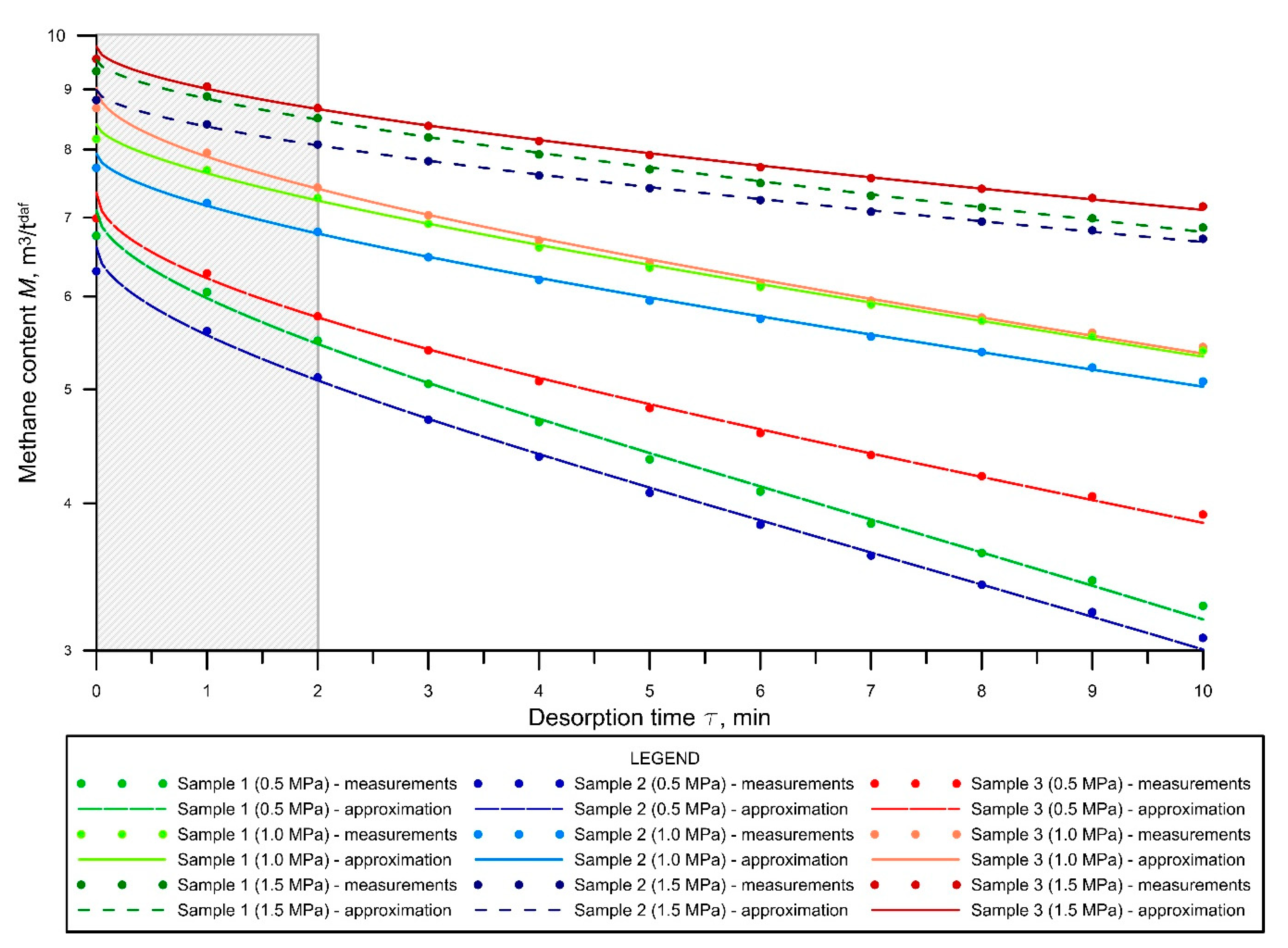
| Sample Number | Saturation Pressure, MPa | Parameter acc. to Equation (3) | Fitted Value | Standard Error | Lower Confidence Limit | Upper Confidence Limit | Coefficient of Determination |
|---|---|---|---|---|---|---|---|
| 1 | 0.5 | = | 7.099 | 0.021 | 7.058 | 7.139 | 0.9964 |
| = | 1.120 | 0.019 | 1.082 | 1.158 | |||
| = | 0.543 | 0.006 | 0.532 | 0.554 | |||
| 1.0 | = | 8.400 | 0.014 | 8.372 | 8.428 | 0.9969 | |
| = | 0.764 | 0.013 | 0.738 | 0.789 | |||
| = | 0.604 | 0.006 | 0.592 | 0.615 | |||
| 1.5 | = | 9.534 | 0.012 | 9.510 | 9.558 | 0.9970 | |
| = | 0.698 | 0.011 | 0.677 | 0.720 | |||
| = | 0.592 | 0.005 | 0.581 | 0.602 | |||
| 2 | 0.5 | = | 6.606 | 0.017 | 6.574 | 6.639 | 0.9974 |
| = | 1.045 | 0.015 | 1.015 | 1.075 | |||
| = | 0.537 | 0.005 | 0.528 | 0.547 | |||
| 1.0 | = | 7.933 | 0.012 | 7.910 | 7.957 | 0.9975 | |
| = | 0.769 | 0.011 | 0.747 | 0.791 | |||
| = | 0.577 | 0.005 | 0.568 | 0.587 | |||
| 1.5 | = | 8.985 | 0.009 | 8.967 | 9.004 | 0.9976 | |
| = | 0.618 | 0.009 | 0.601 | 0.635 | |||
| = | 0.573 | 0.005 | 0.564 | 0.582 | |||
| 3 | 0.5 | = | 7.352 | 0.020 | 7.312 | 7.391 | 0.9968 |
| = | 1.134 | 0.019 | 1.097 | 1.172 | |||
| = | 0.489 | 0.005 | 0.479 | 0.500 | |||
| 1.0 | = | 9.024 | 0.020 | 8.985 | 9.063 | 0.9969 | |
| = | 1.136 | 0.019 | 1.099 | 1.173 | |||
| = | 0.508 | 0.005 | 0.498 | 0.518 | |||
| 1.5 | = | 9.783 | 0.012 | 9.759 | 9.808 | 0.9974 | |
| = | 0.773 | 0.011 | 0.751 | 0.796 | |||
| = | 0.539 | 0.005 | 0.530 | 0.549 |
Publisher’s Note: MDPI stays neutral with regard to jurisdictional claims in published maps and institutional affiliations. |
© 2021 by the authors. Licensee MDPI, Basel, Switzerland. This article is an open access article distributed under the terms and conditions of the Creative Commons Attribution (CC BY) license (http://creativecommons.org/licenses/by/4.0/).
Share and Cite
Szlązak, N.; Obracaj, D.; Korzec, M. Estimation of Gas Loss in Methodology for Determining Methane Content of Coal Seams. Energies 2021, 14, 982. https://doi.org/10.3390/en14040982
Szlązak N, Obracaj D, Korzec M. Estimation of Gas Loss in Methodology for Determining Methane Content of Coal Seams. Energies. 2021; 14(4):982. https://doi.org/10.3390/en14040982
Chicago/Turabian StyleSzlązak, Nikodem, Dariusz Obracaj, and Marek Korzec. 2021. "Estimation of Gas Loss in Methodology for Determining Methane Content of Coal Seams" Energies 14, no. 4: 982. https://doi.org/10.3390/en14040982