1. Introduction to Hyperloop Technology
A passenger traveling to Cleveland from Chicago during a blizzard using Hyperloop as seamlessly and comfortably requires a communication infrastructure that utilizes state-of-the-art, yet existing, technologies. When we began to design this communications system, we looked to an obvious predecessor: High-Speed Rail (HSR) [
1]. With current speeds reaching 600 km/h, HSR has already demonstrated regional economic benefits by shortening travel time. However, HSR has its limits. At higher train speeds, challenges appear, as air friction resistance and wheels on tracks mechanical resistance. As such, aerodynamic drag requires high energy to move the train at higher speeds. Other constraints that appear are noise from wheels and sonic booms when trains exit tunnels due to atmospheric pressure waves being pushed forward.
However, Hyperloop’s enclosed low-pressure environment, at 100 Pa or 1 mbar, drastically reduces aerodynamic drag and noise regardless of operational weather conditions. For reference, to conserve fuel and reduce resistance most planes fly at 11 km above sea level at 76,000 Pa, 100 Pa is obviously more efficient but would be the equivalent of flying at 65 km above sea level. In addition, magnetic propulsion and passive levitation systems utilizing Halbach Arrays eliminate mechanical friction while significantly reducing energy consumption [
2,
3]. As a result, the Hyperloop system can produce more energy than it needs to operate with solar panels on top of the tube, coupled with regenerative braking and low operational energy requirements [
2,
3].
Concerning wireless communications, HST has to use a cellular network parallel to the line, working with propagation in free space. This network is highly influenced by multipath, interference and other factors [
4,
5], which makes it considerably difficult to achieve a high quality of service for broadband communications at speeds of 350 km/h.
About wireless communications, the confined environment of the steel tube used in Hyperloop allows high-frequency signals to be propagated over very long distances, with losses lower than those of free space thanks to guided propagation [
6] and minimizing interferences and multipath. This makes it possible to have high-capacity and high-performance communications with a very low network deployment cost [
7], although there is an important challenge that is the speed of the capsule. In summary, the Hyperloop system was designed to overcome the physical limitations present in high-speed rail at speeds higher than 600 km/h [
8].
In this paper, first, we analyze all the aspects of communications for Hyperloop capsules, describing the communications services and applications needed for critical, performance, and business applications. Then, the different wireless communications systems available for the applications and requirements are carefully reviewed considering the influence of the speed and the performance required. Next, the characteristics of the propagation channel are analyzed, considering the environment of the vacuum tubes and the extremely high speed of the capsules. This propagation study is based on measurements made at different frequencies in tunnel environments and simulations carried out with a ray-tracing simulator that allows for modeling these environments. Based on these results, a design of the two communication networks necessary for critical and passenger communications is proposed. Then, propagation models and tools are described, such as simulators, showing some examples of simulations applied to this case, taking into account the problematic characteristics of Hyperloop propagation such as path loss, Doppler, multipath, and MIMO.
Finally, the conclusions are presented, highlighting the challenges that the development of a communications system for this environment must face.
2. Communication Requirements
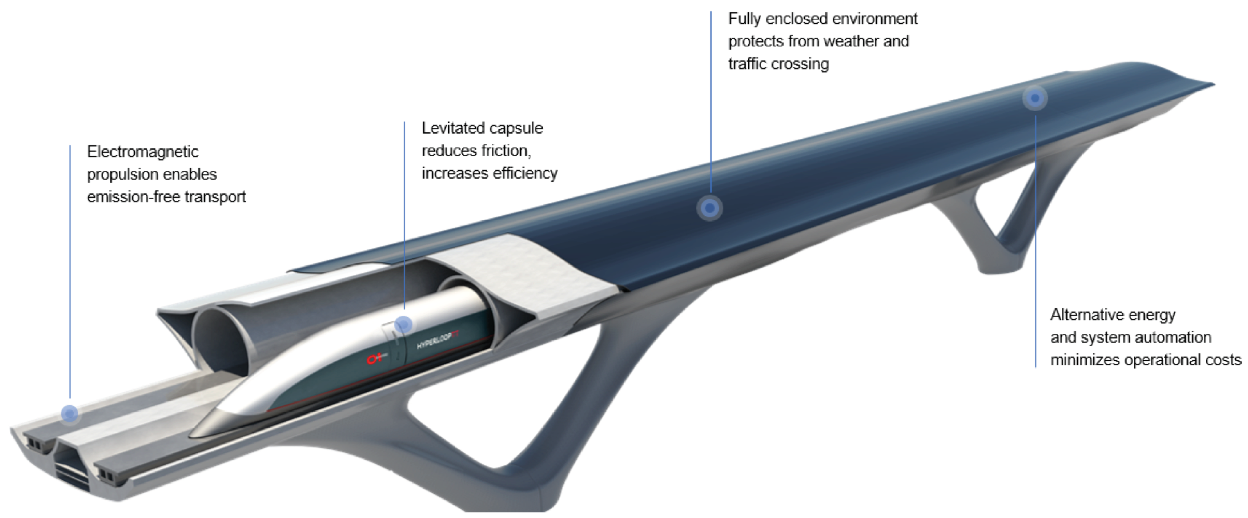
The Hyperloop Transportation Technologies (HyperloopTT) system (
Figure 1) follows three phases of development. In the first phase, a 320 m-long test track has been built with the basic functional characteristics to allow technological tests to be carried out. This facility has been built in Toulouse, France. Simultaneously, a commercial line will be built with a length of 5 km with speeds reach beyond 600 km/h. This line will allow the certification and validation of the technologies developed at high speed and will be able to enter into commercial exploitation with hundreds of kilometer of infrastructure interconnecting towns, cities, and ports.
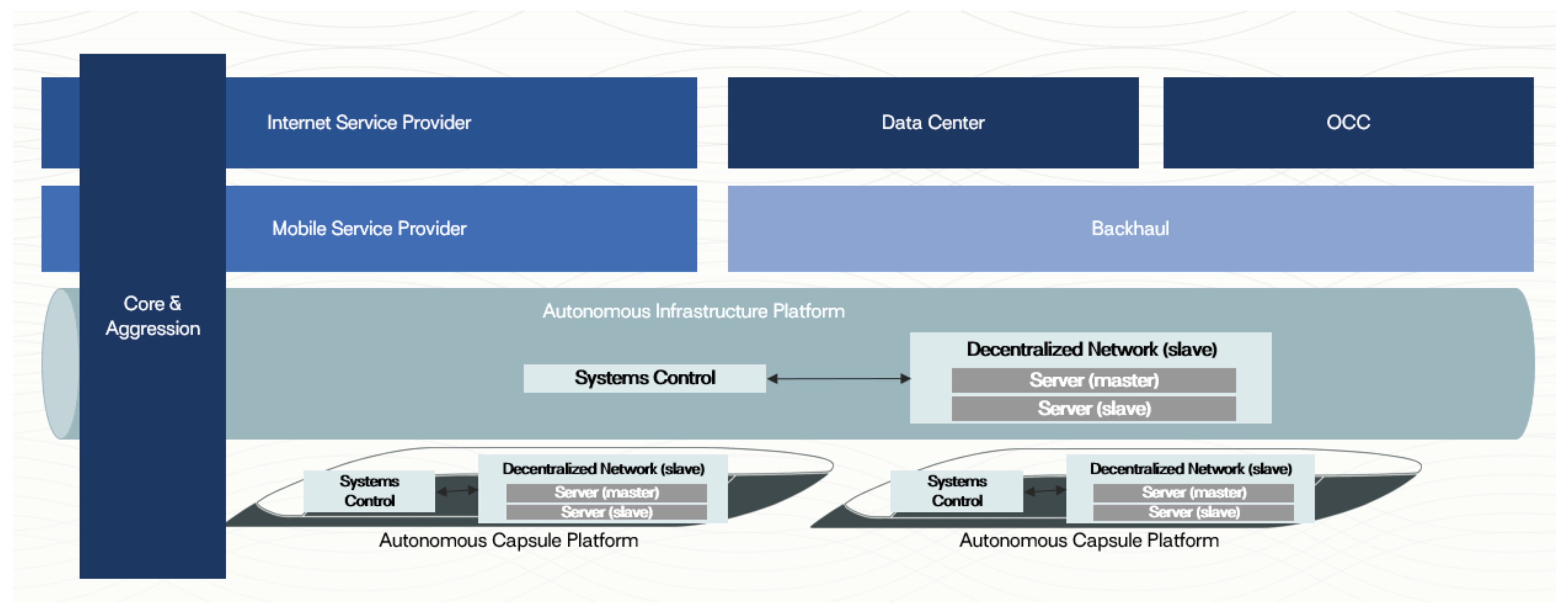
A fully autonomous and connected Hyperloop will require a robust, scalable, reliable network architecture to provide the transfer and flow of critical, performance and business data required on HST [
9] using communications services from the internet and mobile service providers to and from the Operation Control Centre (OCC) to capsule, station, and infrastructure (
Figure 2).
To properly perform Hyperloop communications functions, many different elements of Hyperloop must be interconnected through digital buses or ethernet switches. The following classification of communication-based services are built taking in mind different stakeholders, the criticality/nature of these services, and their end-users:
Critical applications: Continuous data dumping Safety Integrity Level (SIL 4).
Performance applications: Semi-continuous data dumping (SIL 2).
Business applications: Sporadic data dumping (SIL 1).
Critical Communication Applications: Cover all aspects needed for the proper operation of the Hyperloop service. These are mission-critical and safety-related, whereby information generated by these applications must be shared by different stakeholders (e.g., transportation operator and infrastructure operator). This group of systems requires the maximum Safety Integrity Level (i.e., SIL 4 [
10]) to minimize the risk associated with the equipment failure. The bandwidth required is low (less than 10 Mbps per capsule) because the information transmitted is capsule position, speed, and movement authorizations. The most important in this case is extremely significant delay requirements: less than 5 ms delay and less than 1 ms jitter in the worst case. These types of communications usually use UDP packets without retransmissions to minimize jitter and because the signalling information has temporal caducity.
Performance Communication Applications: Include all applications necessary to improve capsule operation and are very similar to advanced HST communications [
6]. These applications will be considered SIL 2 because the security of the capsule does not rely on them. Most important for this application is the on-board 4K real-time video surveillance (CCTV) supporting automatic driving. Video surveillance for the area in front, rear, and inside the capsule is needed to improve operation and security of the passengers and to allow automatic driving. In some ways, CCTV could be considered to be a critical application (SIL 4), but, in this case, it will be very difficult (nearly impossible) to fulfill the delay requirements of the critical communications system, so that they usually are treated as SIL 2. Other performance services are capsule diagnostics and monitoring and passenger information in addition to some basic internet services for the passengers like instantaneous messenger, email, and voice calls that can improve the performance of the capsule and the comfort of the passengers.
Considering all these services, the data rate required is around 100 Mbps with a short delay (<10 ms) and using different wireless communications networks, one for the Hyperloop services and another for the passenger’s performance services. The applications that will be supported include but are not limited to on-capsule voice communication, station public address, wireless data communication for Hyperloop staff at platforms, capsule departure data communications, augmented reality data communication, and real-time translation of speech data communication.
Business Communication Applications: Passengers onboard also expect to access the internet for business and entertainment such as on-vehicle video conference, online games, chatting, live broadcast, etc. These telecommunication services only focus on passengers with no safety consequences requiring a high data rate and good QoS for multimedia information systems and on-demand streaming services [
5].
Typically provided by telecommunication operators, the Hyperloop passenger experience will exceed those of other transportation industries passenger experience in terms of immersiveness and connectivity. Capsules will have augmented reality windows [
11] to help the passenger feel like they are looking outside in the real world although being in an enclosed tube. The applications supported include information help points for the public, emergency help point for the public, wireless internet on-capsule for passengers, and wireless internet for passengers on platforms.
In
Table 1, we give a summary of the requirements of communications.
3. Design of the Communication Networks
The design of the communications networks necessary for the operation of the Hyperloop capsules is similar to that of modern high-speed and metropolitan railways that operate in an automated way [
12,
13]. The wireless communication systems of HSR, intercity railway, subway, light rail, and other rail traffic are deployed with various wireless standards [
5,
14]. To ensure safe and reliable operation of railways, these wireless standards have to be reliable and robust. In addition, due to the ultra-high operation speed, extremely low end-to-end delay and handover delay are required for operational services transmission, such as train location information. Typically, advanced HST and metros use two separate networks, one for critical communications that are used to control trains and a second network that is used for operating aid and passengers [
15]. All of these communications are T2I (Train to Infrastructure), T2P (Train to Passengers), although in the last few years, some metros have implemented T2T (Train to Train) communications to perform train convoys [
16].
Hyperloop capsules will communicate with multiple entities using wireless communication systems and local area network (LAN) infrastructure. Adopting a similar concept of V2X (Vehicle-to-everything), a C2X (Capsule-to-everything) communication framework will provide the backbone for passing information from capsule to any entity that may affect the capsule and vice versa. This capsule communication system incorporates other more specific types of communications such as C2I (capsule-to-Infrastructure), C2G (Capsule-to-Grid), C2P (Capsule-to-Passenger), C2C (Capsule-to-Capsule), and C2N (Capsule-to-Network). C2X can be supported by the underlying communication technologies such as WLAN (Wi-Fi 6) and cellular fifth-generation new radio (5G NR). On
Table 2 we summarise this communications.
Traditionally, critical communications in HST use a European Railway Traffic Management System (ERTMS) [
17] for train control and monitoring, and it is composed of Global System for Mobile Communications-Railway (GSM-R) that contains both a voice communication network between driving vehicles, line controller, and a bearer path for European Train Control System (ETCS) data.
Existing rail communication systems include the nearing obsolescent GSM-R and a replacement for the FRMCS (Future Railway Mobile Communications System) [
18] based on 5G NR technology. Nevertheless, this new standard limits their support to trains traveling at 600 km/h or less, but it’s important for HST because it provides interoperability between trains of different countries.
For urban transit rail systems, WLAN based on IEEE 802.11xx is currently a prevalent choice due to the available commercial-off-the-shelf equipment. However, WLANs are not specifically designed for high mobility scenarios and there are some problems for WLAN-based Communications-Based Train Control (CBTC) systems such as handoff and QoS issues [
19].
The 38 GHz millimeter Wave (mmW) wireless communication technology is applied in the Shanghai Maglev system [
20]. The 38 GHz mmW system could provide a capacity that reaches up to 100 Mbps, but also ensure a delay of less than 5 ms and the Bit Error Rate (BER) of safe-related data transmission on the order of
.
The mmW communication system is also a candidate for the system offering high-speed communication services in HSR. The Distributed Antenna System based the 28 GHz millimeter Wave mobile communication system for HSRs analyzed the potential of the system through the computer simulations, showing that the enormous throughput exceeding 2 Gbps can be achieved in the HSR moving at a speed of 400 km/h [
21].
As Hyperloop will use ERTMS, with GSM-R becoming obsolete in 2030, proprietary solutions based on Wi-Fi 6 and 5G NR are proposed for critical/performance/passengers communications at very high vehicle speed, which is a great challenge. The 5G NR communication system combined with a Wi-Fi 6 (IEEE 802.11ax) will be the basis of the Hyperloop wireless communication system.
In
Table 3, there is a comparison of the available standards for HSR and Metro communications. Nowadays, the performance of Wi-Fi 6 and 5G is insufficient for Hyperloop, with proposed speeds approaching 1200 km/h and a data rate far exceeding 1 Gb/s per capsule, but using this standard on a confined environment with guided propagation allows for the use of multiple bands including 2.5/5.7/24/28/34/66 GHz with potentially delivering 10 times the throughput of current systems, and converging with an edge-computing network architecture will help to overcome all these challenges to guarantee safe operation and real-time passenger data requirements traveling near the speed of sound.
The design of the communications network will play a crucial role by providing integrated operations, allowing for scalability, automation, safety, and security for the entire Hyperloop infrastructure. The basic architecture is shown in
Figure 3. These are two different networks, one operating with WiFi 6 technology for critical/performance communications and the other 5G for performance and business communications.
The use of WLAN technology allows access to a standardized technology whose medium access layer is controllable [
22] and which can operate in bands commonly used throughout the world. On the other hand, the implementation of a 5G network with more distance between base stations and using “moving relays” in the capsules [
23] will allow the provision of 5G services to passengers with their own terminals. With a new spectrum available for Hyperloop, both operators and passengers will benefit from increased data rates, high QoS, low-latency, high capacity, great IoT coverage, and power efficiency to support a fully autonomous Hyperloop. Additionally, as a greenfield project, Hyperloop, unlike railway, will not require a capital intensive migration from existing GSM-R or LTE-R to 5G. In the following point, we analyze all the propagation aspects and problems of the communications system.
4. Propagation and Challenges of the Wireless Communication
The special characteristics of the Hyperloop tube and ultra-high-speed capsule impose numerous challenges on the design and evaluation of the capsule to ground wireless communication systems [
8]. Nevertheless, the high mobility and fully enclosed vacuum tube wall also provide a continuous environment, with some similarities to railway tunnels that can be exploited to facilitate system designs and to improve system performance. The key challenges for the design of capsules wireless communication are listed as follows:
Propagation: fully guided in a metal tube with high conductivity.
Doppler shift—extremely high Doppler shift especially at microwave frequencies can cause significant variation of the received signal.
Handover—high speeds make it difficult and virtually impossible with current technology and network design. MAC layer of the wireless communication system needs to be modified.
Delay Spread: can be very variable due to the all-metal steel and carbon fiber structure. Must be carefully characterized.
Penetration losses: are high although design or access and emergency doors and other connections of the tube can reduce it.
MIMO capabilities are very limited as happens in HSR environments.
Propagation characteristics in the tube: the knowledge of the wireless channel that has a close relationship with propagation scenarios is the fundamental basis. The environment is similar to traditional railway tunnel scenarios [
24] with the difference that the Hyperloop is operating inside a fully enclosed metal tube wall resulting in a special propagation environment for wireless signal that has a guided propagation with a high pass response with potential low losses at high frequencies.
From the aspect of guided propagation, the concept of “modal propagation“ can be used to analyze the propagation characterization of radio waves in the tube [
25]. Based on this theory, the high-order mode gradually decays and disappears as the distance between transmitter and receiver increases only leaving the low-order mode. Thus, we have two propagation zones and a breakpoint [
26] (BP) that can be computed to distinguish both zones. At lower frequencies, attenuations are higher in the region close to the antenna where multimodal propagation is dominant. Losses become lower when we pass the BP, and there is only propagation of the dominant mode.
The attenuation losses of the different modes (
) can be computed with the following equation for modal analysis [
27]:
where
f is the frequency, and
(width/height) are the dimensions of the free area inside the tube that can be approximated as
(4 m for Hyperloop). Then, “
m” and “
n” are the index of the mode and “
” is the complex permittivity of the tube walls defined as:
where
is the real permitivity,
is the wavelength,
is the conductivity of the walls (S/m),
c is the speed of light in vacuum and
is a newly introduced constant (
: Vacuum permeability).
Then, using steel on the walls with high conductivity (
Table 4), we can compute propagation losses as:
Thus, for high frequencies and large tube diameter, we have hundreds of modes (
) propagating with high losses on the region close to the antenna. As attenuation increases with the order of the model (
), far from the antenna, we have only low order mode (1,1) propagation with low losses. These two regions can be distinguished as defining a “BreakPoint” [
24]. We can compute the breaking point according to the equation:
In
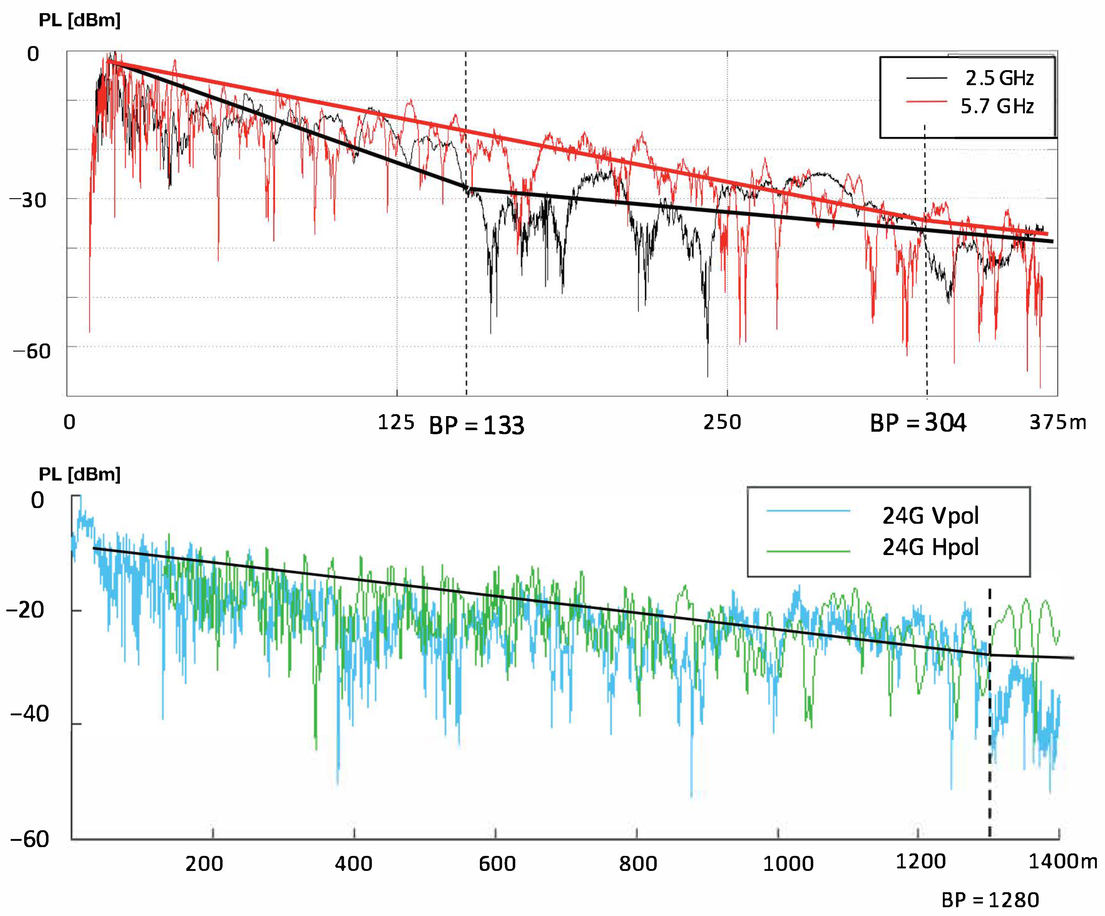
Figure 4, we can see an example of measurements at two different frequencies on subway round tunnel of 4 m diameter at 2.5/5.7 and 24 GHz [
28], and, in
Table 5, we have the results of BP and path loss for different frequencies. In this case, the tunnel walls are made of concrete with a dielectric constant of
= 5 and low conductivity (
). We can see that BP distance becomes larger as frequencies increase and path losses decrease also with frequency. Thus, the use of high frequencies is better for propagation in confined environments like tunnels.
In metal vacuum tubes, we expect even lower losses due to the permittivity and conductivity of the walls. In
Figure 5, we can see two simulation made with a propagation simulator [
29] for a steel tube of 4 m diameter, straight 1000 m length with a capsule in the middle and curved 3000 m. The frequency of the site antenna 2.5 GHz with a transmit power of 0 dBm and the parameters of the simulation are given in
Table 5. In this case, we can see that the losses from the BP (133 m) to the capsule (500 m) the received power changes from −60 dBm to −75 dBm so that losses are 4 dB/100 m, similar to that in subway tunnels. In addition, 23 dBm power at 2.5 GHz could have a cell.
In the straight tunnel, we can see the path losses from the BP (133 m) to the capsule (500 m), the received power changes from −60 dBm to −75 dBm so that losses are 4 dB/100 m, similar to that in subway tunnels. In addition, 23 dBm power at 2.5 GHz could have a cell.
In the curved tunnel, we can see that there is a high attenuation (50 dB) of the signal due to the shadowing effect of the capsule, so that, on a real network, there must be a strong overlap of the coverage of two neighborhood antennas.
With this results of path loss, a system like 802.11xx with a radius of up to 2.5 km and a 5G system working in mmW band (28/34 GHz) with 50 dBm Isotropic Radiated Power could reach a 3.5 km cell radius, minimizing the need of handovers and allowing a good overlap of cell radius.
Handover: Is necessary to maintain the connection active while moving from one cell to another. Due to the ultra-high velocity, there is a very short time to perform the handover as this is one of the key points of the communications system, and it must be minimized. The handover times of current HSR using the GSM-R system are on the order of 300 ms and requires six seconds of signal overlap of two cells. These requirements limit a “hard” handover to a top speed of 400 km/h, and this is absolutely unacceptable for Hyperloop capsules. Therefore, it is necessary to use soft handovers and having the capsule continuously linked to two neighboring cells will have a moderate overlap. In addition, with the capsule traveling at 333 m/s (1200 km/h), the cell radius of the communications system must be as long as possible (>330 m) to allow a maximum cell reselection time of 1 s.
Doppler shift: Is another of the key elements of the system. For example, Doppler shifts at 24 GHz at top speed (1200 km/h) is ±26.6 kHz and can have an important influence on the communications. Maximum Doppler shift is obtained when the capsule passes behind the antennas so that it’s important to configure the communications system to operate with Doppler requirements. Thus, in the multi-carrier systems, such as Orthogonal Frequency Division Multiplexing (OFDM) used on 802.11xx or 5G NR, this parameter is configurable [
30] and the requirements are:
In addition, as Doppler shift is deterministic in tubes, Doppler cancellation [
31] can be included on the MAC Layer of the communications systems to reduce the impact. This is applicable for 802.11xx systems that can be adapted to operate in this environment.
Delay spread: A secondary effect of the speed is the multipath inside the tube due to reflections in an element like intermediate doors, track, antennas, and any discontinuity of the surface of the tube. This multipath will produce time-varying Doppler spreads and non-stationary fading [
32] that will produce the overlapping of the sub-carriers and therefore will introduce Inter-Carrier Interference (ICI). ICI will seriously degrade the synchronizer performance and increase the system bit error rate. These problems can be overcome using an expanded intercarrier spacing that will reduce throughput but will increase robustness against ICI. 5G NR can be configured with a subcarrier spacing up to 240 kHz while 802.11xx can have up to 312.5 kHz. With this configuration, it will be possible to minimize ICI; nevertheless, it is necessary for accurate modeling and testing of propagation inside the tube using channel sounders [
33] and propagation measurements to optimize propagation, especially in sections like emergency exits and at the tops of the capsule and to model the influence of the linear synchronous motor track.
Penetration loss: As is mentioned above the Hyperloop capsule, is operating in the hermetically sealed vacuum tube. To ensure the airtightness, the tube walls are made of steel and so those penetration losses of the tube can be in the range of 40–60 dB if the system is carefully designed so that we can consider that it is a confined space without external interferences and does not require frequency sharing compared with a conventional system. This is especially important for the use of Wi-Fi 2.5 GHz and 5 GHz ISM bands.
The capsule is made of carbon fiber without windows so penetration losses are very high (40–60 dB) and must be equipped with external antennas and repeaters to provide coverage inside.
MIMO capabilities: The use of MIMO in tunnel environments is very limited due to the propagation characteristics of the channel and the difficulty of positioning the antennas with the optimal separation and orientation [
34]. The linear propagation in tunnels makes the different propagation channels highly correlated [
35]; therefore, the capacity improvement achieved using MIMO is small. To reduce the spatial correlation, it is necessary to separate the antennas considerably, which makes deployment difficult, and is not always possible, especially on the capsule side. Therefore, the use of MIMO in tunnels is usually limited to 2 × 2 configurations with a large separation of antennas at the base that allows for achieving a performance improvement.
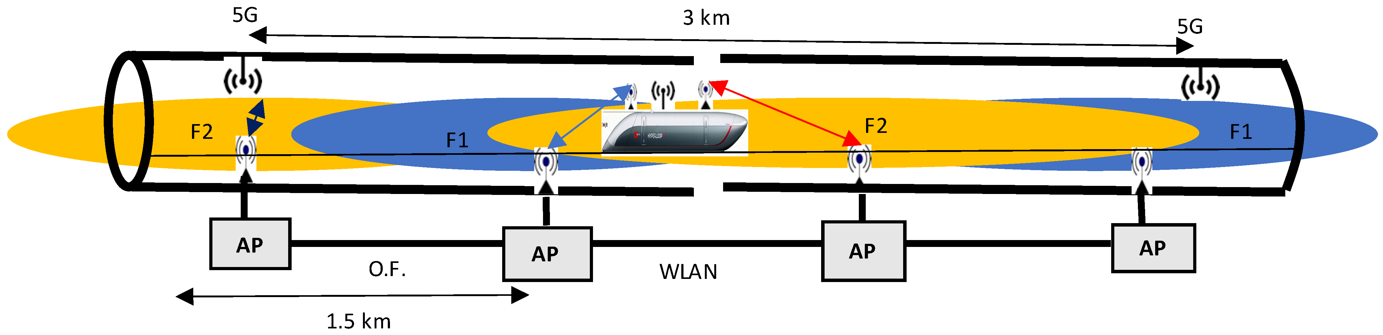
Therefore, considering the excellent propagation conditions in the tunnel, we could have 1 km cell radios at 2.5 GHz/5.7 GHz frequencies working on the ISM bands of 802.11xx (23 dBm) for critical communications. This network could be designed with a strong overlap that would guarantee redundancy and allow sufficient time to complete the handovers and using two frequencies to ato allow frequency and spatial diversity.
This interval would be 3 s traveling at 1200 km/h. The capsule would be simultaneously connected to two neighboring cells, see
Figure 6, using two different frequencies (F1 and F2) in such a way that there would be no loss of data in the event of failure of one of the links and the handover process would be facilitated. MIMO 2 × 2 can be used deploying a set of two antennas in the front and rear of the capsule and the same in the base.


