Modeling of German Low Voltage Cables with Ground Return Path
Abstract
:1. Introduction
2. Monitoring of Real LV Feeders
2.1. Detailed Measurement of Line Currents
2.1.1. Breakdown of Feeder Currents
2.1.2. Time Dependency
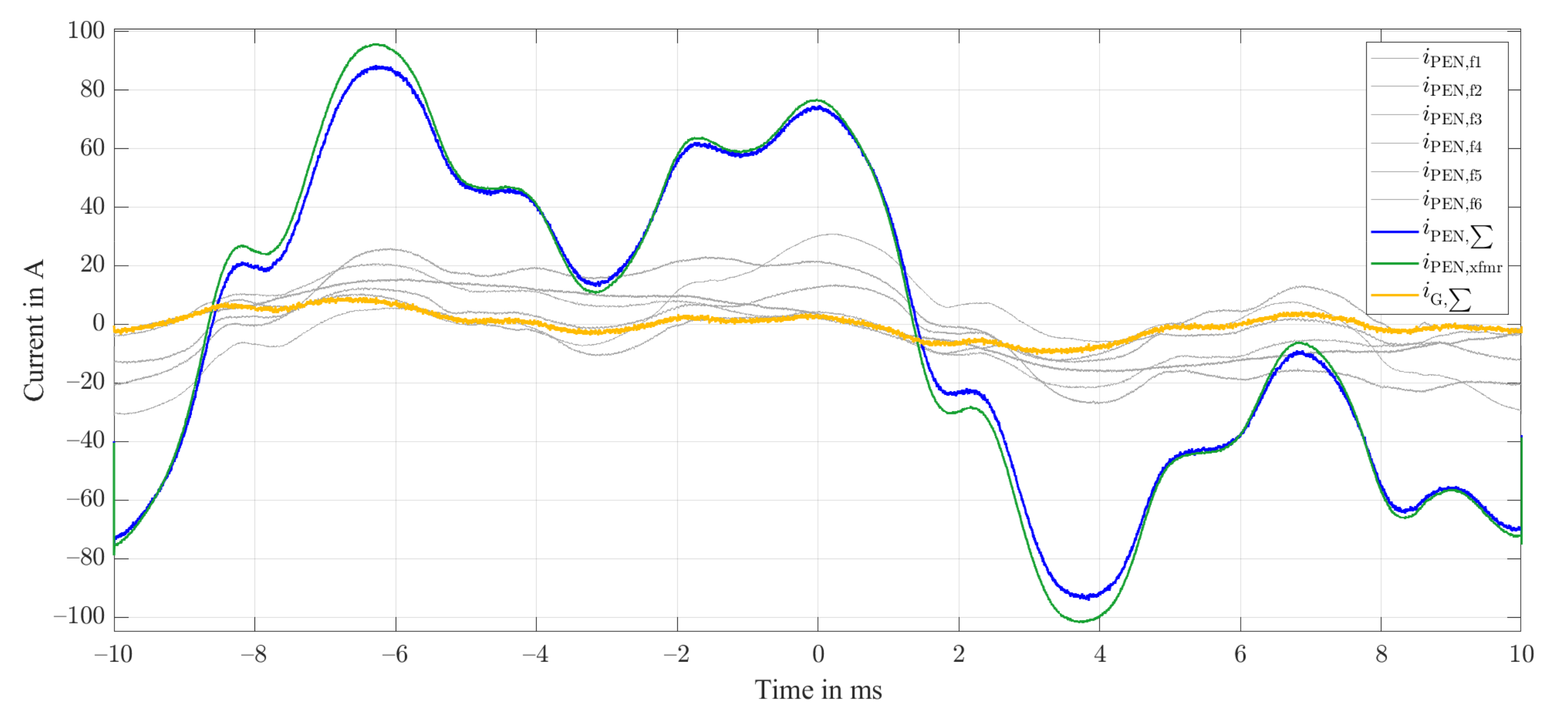
2.2. Measurements at Substation PEN Busbars
2.3. Conclusions
3. Modeling Approaches of Low Voltage Cables and Grounding
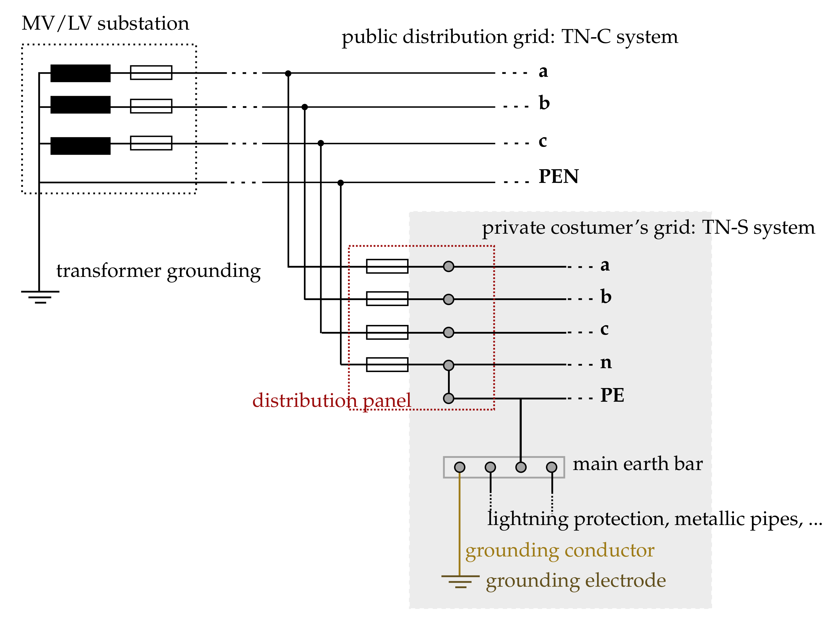
3.1. German LV Grid as TN-C-S System
3.2. Conventional Modeling Approaches
3.2.1. Handling of Shunt Admittances
3.2.2. Temperature-Independent Parameters
3.2.3. Modeling in Symmetrical Components
3.2.4. Carson’s Equations for Ground Return Path Modeling
Primitive Circuit Impedances
Kron’s Reduction
Applicability To German Low Voltage Grids
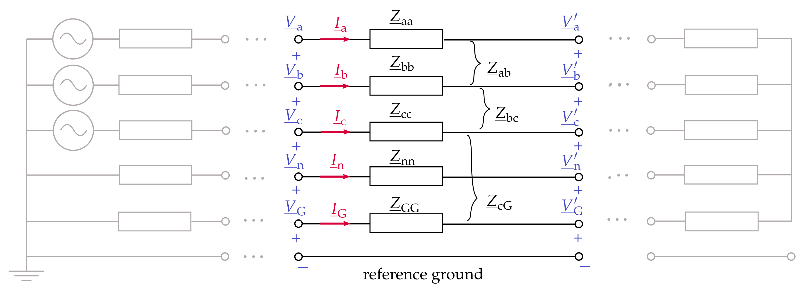
3.3. Alternative Modeling Approach: Ground as Single Electrical Point
- Cable parameters The depicted cable parameters in Figure 7, , , , and , only depend on cable design and materials. For these parameters, we present calculation methods in Section 4.2 and evaluate these with laboratory measurements of real low voltage cables in Section 4.3.
- Ground/Ground return path Capacitance to ground , as well as impedances and , vary depending on the cable’s real installation conditions and can, therefore, not be determined through laboratory measurements. We present exemplary reference values in Section 4.2.3 and Section 5.
4. Low Voltage Cable Parameter Determination
4.1. Assumptions and Simplifications
4.1.1. Influence of Cable Lay Length
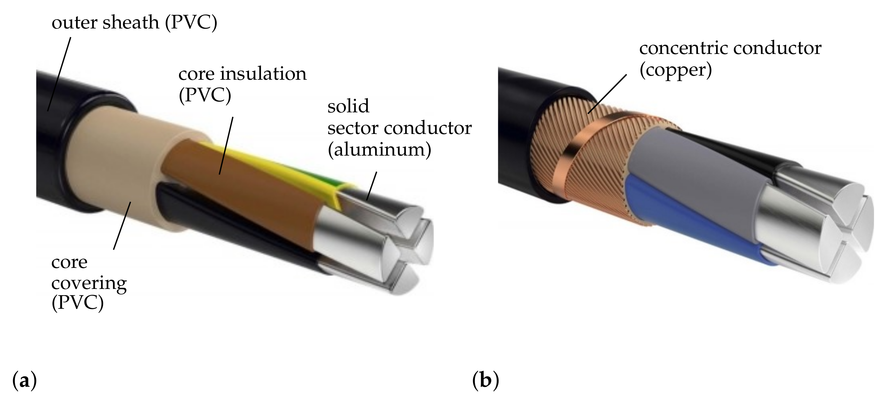
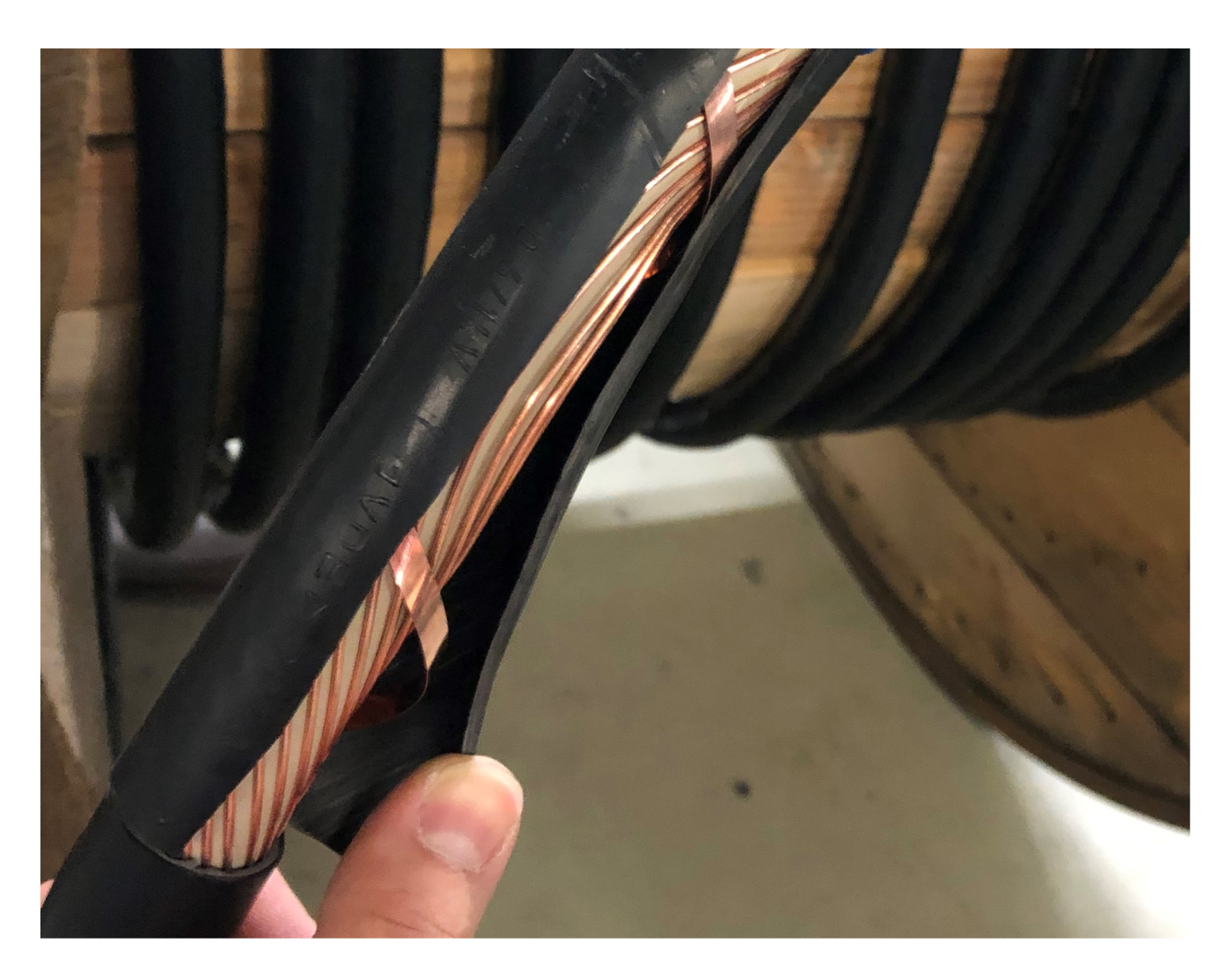
4.1.2. Idealization of the Concentric Conductor
4.2. Calculation of Cable Parameters
4.2.1. Ohmic Resistances
4.2.2. Self and Mutual Inductances
| GMR | sector-shaped conductor | ||
| GMR | shield | ||
| GMD | horizontally/vertically neighboring sector- shaped conductors | three-core cable four-core cable | |
| GMD | diagonal conductors | four-core cable | |
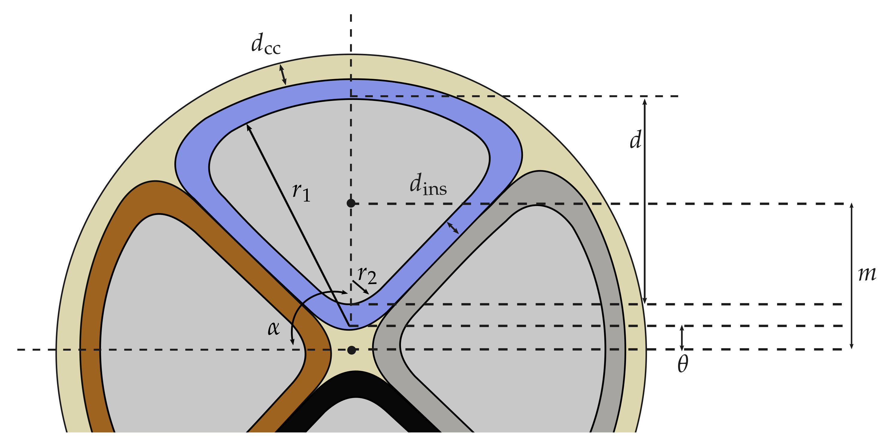
| GMD | sector-shaped conductor–shield |
Geometric Mean Radius of Sector-Shaped Conductors
Geometric Mean Distance Between Sector-Shaped Conductors
Geometric Mean Radius and Distance of the Concentric Shield
4.2.3. Capacitances
4.3. Experimental Determination of Cable Parameters
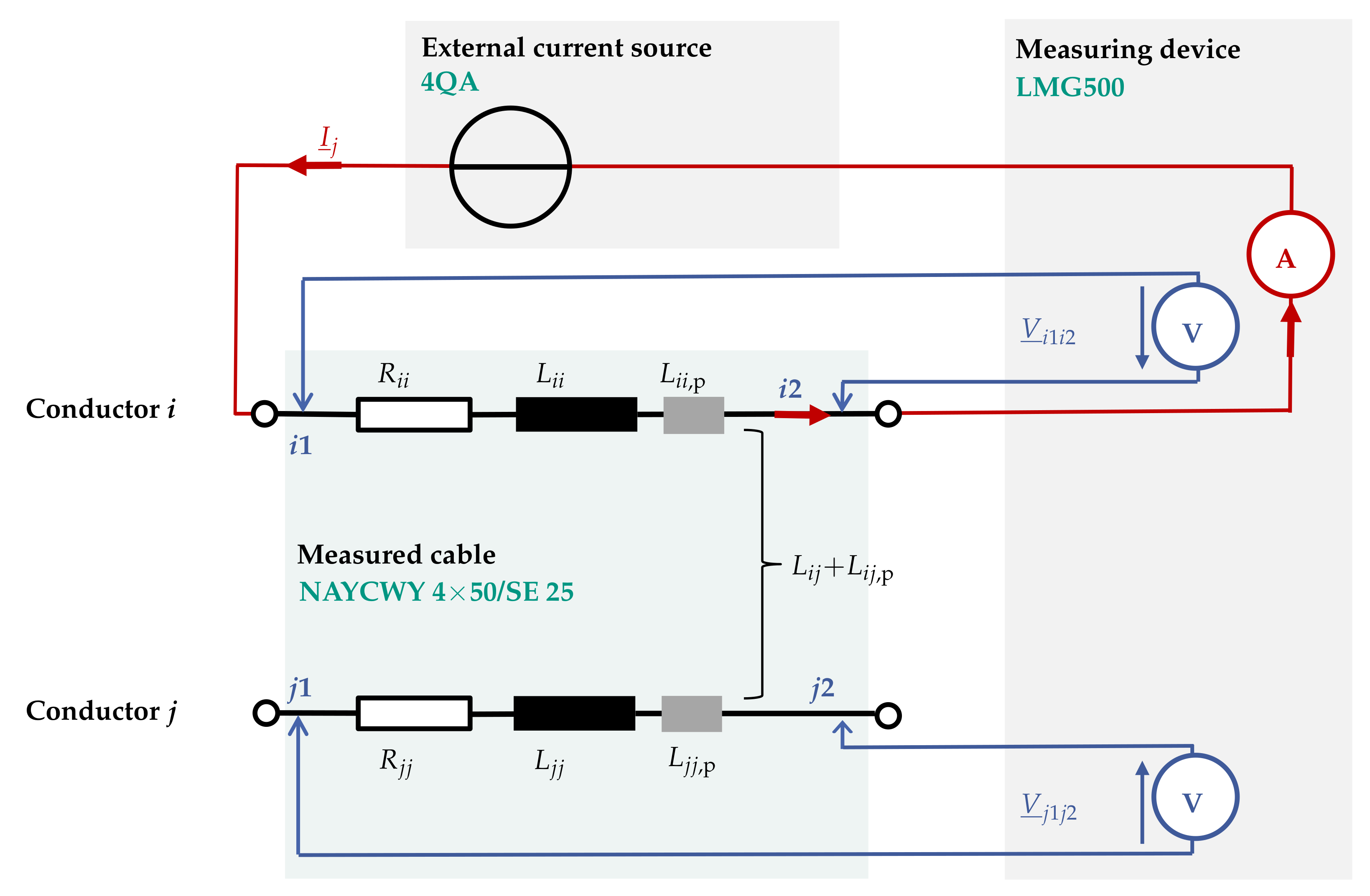
4.3.1. Resistances and Inductances
4.3.2. Capacitances
4.4. Comparison and Analysis of Calculated and Measured Cable Parameters
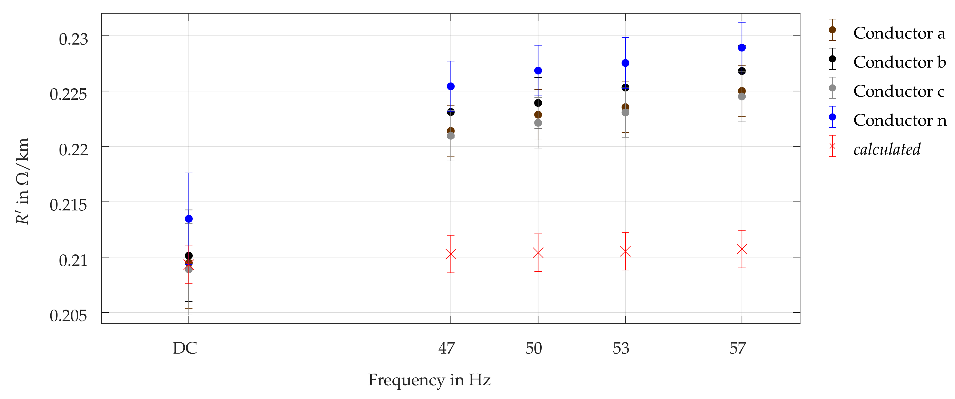
4.4.1. Conductor Resistances
4.4.2. Self and Mutual Inductances
- Stray magnetic flux Due to the finite length of test cables, stray magnetic flux at the cable ends can distort measured inductances. Nevertheless, this influence should actually become less relevant with an increasing length of the test object.
- Test cable setup As described in Section 4.3, test cables were installed in a U-bend, forming a kind of one-turn loop. This most likely leads to an increase in both self inductance and mutual coupling between the conductors.
- Laboratory environment Influences on the magnetic field due to the floor and other possibly magnetizable surfaces and components in the test cable surroundings cannot be excluded.
- Approximate formulas Equations (15) and (16) for calculation of self and mutual inductances were originally developed for round and infinitely long conductors, relatively far distanced from each other compared to their radius. Thus, for sector-shaped conductors with large cross-sectional areas and comparatively small geometric mean distances between them, the accuracy of the approximation is questionable.
4.4.3. Capacitances
5. Grounding Impedance of Grid Nodes
5.1. System Identification and Parameter Definition
5.2. Grounding Impedance of Typical Households
5.3. Grounding Impedance of Substations
6. Parameter Relevance and Sensitivity
6.1. Setup of Test Feeder Model for Parameter Analysis
6.1.1. Modeling of Transformer, Cable Segments and Grounding
6.1.2. Modeling of Load Distribution
6.2. Modifications in Modeling the Cable Components
6.2.1. Neglecting Electrical or Magnetic Coupling between Conductors (S1a, S1b)
6.2.2. Neglecting House Junction Cables (S2)
6.2.3. Variation in Conductor Temperature (S3a, S3b)
6.2.4. Modifications in Modeling the Ground Return Path (S4a–S4c)
6.3. Modifications in Connection Phase
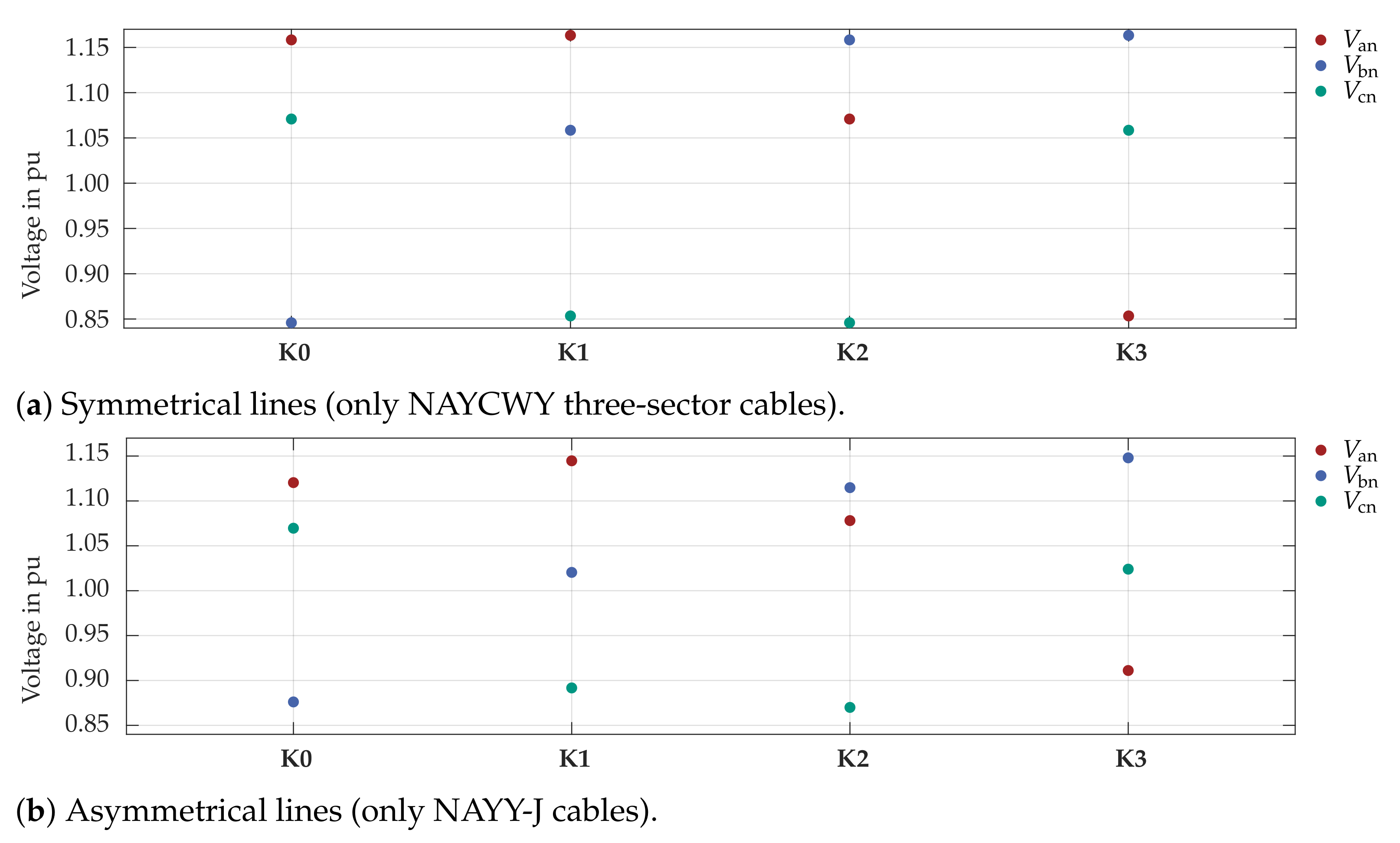
6.3.1. Line Model: Symmetrically Designed NAYCWY Three-Core Cable
6.3.2. Line Model: Asymmetrically Designed NAYY-J Four-Core Cable
6.4. Conclusions of Simulation Model Variations
- Capacitances: For our investigations, capacitances are neglectable at 50 , at least compared to the impact of other modeling inaccuracies.
- Inductances Mutual inductances between conductors can have a substantial impact on simulation results, particularly for asymmetrically designed lines.
- House junction cables: Typical LV grid simulations neglect house junction cables. However, as results show, for detailed modeling of LV grids the impact is not negligible due to the rather high impedance of typically utilized cables.
- Conductor temperature: Assuming a conductor temperature of 70 might be unrealistic, but is still relevant for worst-case scenarios, since changes in conductor resistance due to temperature increase have a major influence on phase voltages. Especially for highly loaded grids, modeling of cable temperature should be considered.
- Ground return path: Our investigations have shown that modeling of the ground return path is relevant when simulating grids with multiple groundings, since deleting all grounding impedances in our model significantly increases voltage asymmetry. Small changes in the range of a few in the costumer buildings grounding impedances , however, only lead to small changes in simulated voltages. This validates the idea of using exemplarily calculated reference values for parametrization of (see Section 5.2).
- Load distribution & phase sequence: As shown, distribution of loads to phases and corresponding phase sequence have a major impact on simulation results. This impact is considerably bigger for asymmetrically designed lines. Thus, for worst-case studies aiming at estimating most critical voltage values, careful considerations of potential load distribution have to be carried out.
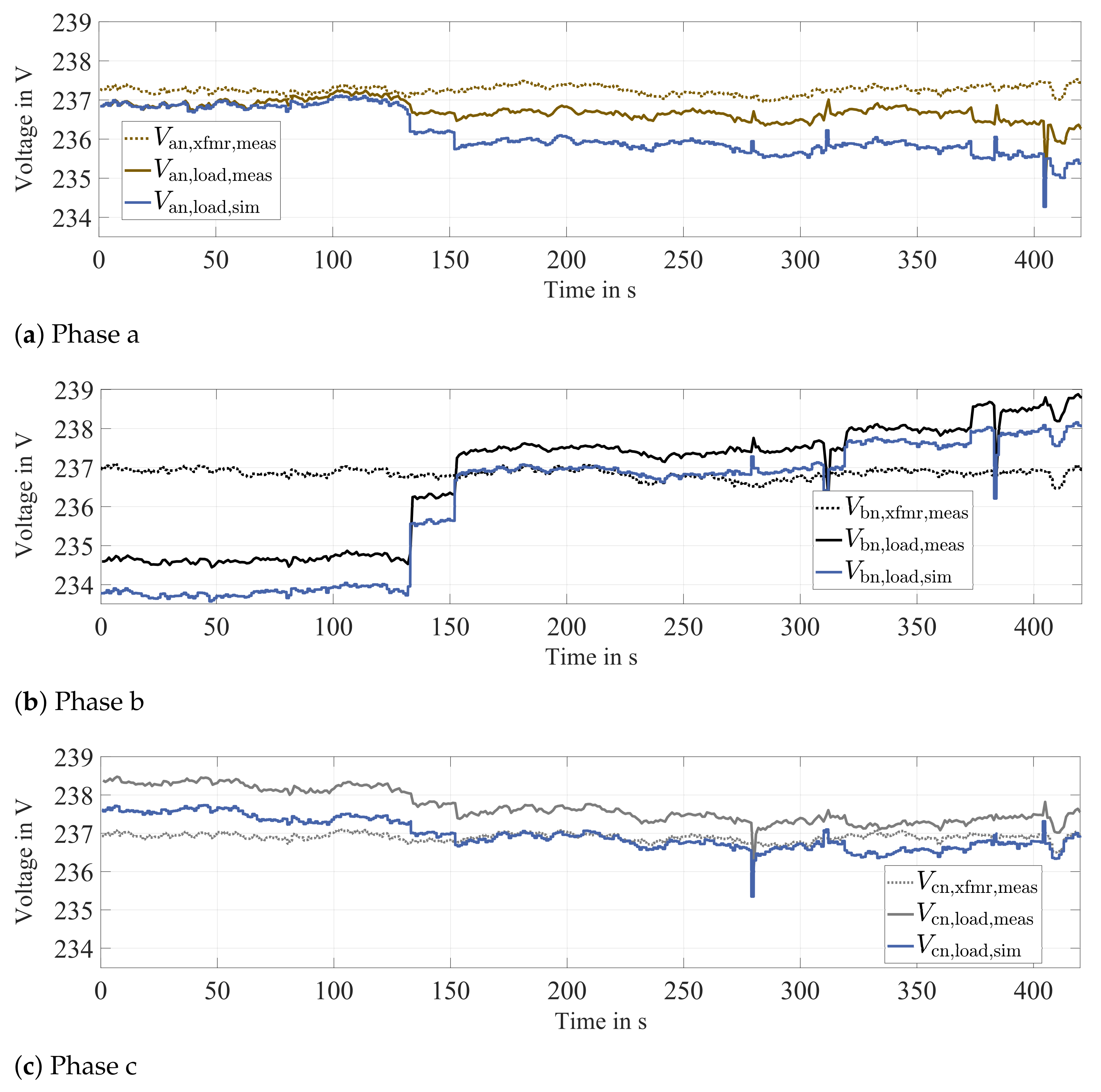
7. Model Validation with Data from Real LV Feeder
- Inaccurate model parameters As discussed in Section 4.4.1 and Section 4.4.2, calculated resistance and inductance parameters differ from those values measured at test cables. This indicates that discrepancies between assumptions made for calculation of parameters and reality do exist. In addition, conductor temperature might have been different to the assumed 20 .
- Grounding model & impedances Only one feeder is simulated; thus, ground currents are forced to return to the transformer. In reality, ground currents possibly take different paths, thus influencing real voltages (see Section 3.3). In addition, grounding impedances are parametrized based on measurements of another day, when ratio of PEN to ground currents most likely was different.
- Feeder setup simplifications For the simulations carried out in this Section, the original feeder A-2 (see Figure 18) was reduced to three nodes. Hence, additional inaccuracies concerning individual grounding impedances and phase loads—and resulting ground currents—can be seen as possible reasons for discrepancies between simulated and measured phase voltages.
- Measurement results & feeder data Even though measurements were carried out with reasonable care, inaccuracies in measurement data and noise, as well as in available grid data, cannot completely be excluded.
8. Conclusions
8.1. Derivation and Parametrization of an Alternative Modeling Approach
8.2. Analysis of Parameter Relevance and Sensitivity
Author Contributions
Funding
Acknowledgments
Conflicts of Interest
Appendix A. Model Parameters Calculated acc. Section 4
| NAYY-J 450 SE | NAYCWY 350 SE/50 | NAYCWY 450 SE/25 | |
|---|---|---|---|
| Resistances in (from Reference [6]) | |||
| 0.641 | 0.641 | 0.641 | |
| – | 0.641 | 1.20 | |
| Self inductances in | |||
| 1.168 | 1.168 | 1.168 | |
| – | 0.909–0.919 | 0.882–0.892 | |
| Mutual inductances in | |||
| 0.940–0.951 | 0.940–0.951 | 0.940–0.951 | |
| 0.871–0.882 | – | 0.871–0.882 | |
| – | 0.909–0.919 | 0.882–0.892 | |
| Capacitances between conductors | |||
| 0.09–0.15 | 0.08–0.12. | 0.09–0,15 | |
| 0.00–0.01 | – | 0.00–0.01 | |
| – | 0.25–0.38 | 0.22–0.33 | |
| Capacitances to ground (from Reference [6]) | |||
| 0.48 | – | – | |
| – | 0.48 | 0.48 | |
| NAYY-J 4150 SE | NAYCWY 3150 SE/95 | ||
| Resistances in (from Reference [6]) | |||
| 0.207 | 0.207 | ||
| – | 0.320 | ||
| Self inductances in | |||
| 1.058 | 1.058 | ||
| – | 0.819–0.827 | ||
| Mutual inductances in | |||
| 0.848–0.856 | 0.847–0.855 | ||
| 0.779–0.787 | – | ||
| – | 0.819–0.827 | ||
| Mutual capacitances between conductors in | |||
| 0.12–0.19 | 0.1..0.16 | ||
| 0.01 | – | ||
| – | 0.33–0.49 | ||
| Capacitances to ground in (from Reference [6]) | |||
| 0.66 | – | ||
| – | 0.66 | ||
Appendix A.1. Meaning of Subscripts
| CC / SS | Sector-shaped conductor / shield to itself (self impedance: resistance and self inductance) |
| LS | Sector-shaped conductor–shield pairs |
| HV | Horizontal/vertical sector-shaped conductor pairs |
| Diag | Diagonal sector-shaped conductor pairs |
References
- Schwab, A.J. Elektroenergiesysteme, 4th ed.; Springer Vieweg: Wiesbaden, Germany, 2015. [Google Scholar]
- Pardatscher, R. Planungskriterien und Spannungsqualität in Mittel- und Niederspannungsnetzen mit hoher Photovoltaik-Einspeisung. Ph.D. Thesis, Technical University of Munich, Munich, Germany, 2015. [Google Scholar]
- De Castro, D.B.; Rezania, R.; Litzlbauer, M. V2G-Strategies: Auswirkung verschiedener Elektromobilitätsszenarien auf die Spannungsqualität von Niederspannungsnetzen unter Betrachtung der Phasenunsymmetrie. In Proceedings of the 12th Symposium Energieinnovation, Graz, Austria, 15–17 February 2012. [Google Scholar]
- Wagler, M.; Witzmann, R. Effects of asymmetrically connected PV and battery systems on the node voltages and pen-conductor currents in low-voltage grids. In Proceedings of the 24th International Conference & Exhibition on Electricity Distribution (CIRED), Glasgow, UK, 12–15 June 2017. [Google Scholar]
- Bundesverband der Energie- und Wasserwirtschaft e. V. (BDEW). Länge des Deutschen Stromnetzes. Available online: https://www.bdew.de/media/documents/PI_20181204_Zeitreihe-Stromnetze.pdf (accessed on 5 March 2020).
- Oeding, D.; Oswald, B.R. Elektrische Kraftwerke und Netze, 8th ed.; Springer Vieweg: Wiesbaden, Germany, 2016. [Google Scholar]
- Kerber, G. Aufnahmefähigkeit von Niederspannungsverteilnetzen für die Einspeisung aus Photovoltaikkleinanlagen. Ph.D. Thesis, Technical University of Munich, Munich, Germany, 2011. [Google Scholar]
- elektro4000.de. Available online: https://www.elektro4000.de/Kabel-Leitungen/Kabel/Starkstromkabel/Verschiedene-Diverse-K-L-NAYY-J-4x150-SE-Eca-S-NAYY-J-4x150-SE-Eca::4302.html (accessed on 6 March 2020).
- elektro4000.de. Available online: https://www.elektro4000.de/Kabel-Leitungen/Kabel/Starkstromkabel/Verschiedene-Diverse-K-L-NAYCWY-4x-25-RE-16-S-NAYCWY-4x-25-RE-16::1024075.html (accessed on 6 March 2020).
- Kiefer, G.; Schmolke, H. VDE 0100 und die Praxis, 16th ed.; VDE-Verlag: Berlin, Germany, 2017. [Google Scholar]
- Niemand, T.; Schröder, A. Erdungsanlagen, 2nd ed.; VDE Verlag: Berlin, Germany, 2016. [Google Scholar]
- Kasicki, I. Elektrotechnik für Architekten, Bauingenieure und Gebäudetechniker—Grundlagen und Anwendung in der Gebäudeplanung, 2nd ed.; Springer Vieweg: Wiesbaden, Germany, 2018. [Google Scholar]
- Markiewicz, H.; Klajn, A. Erdungsysteme—Grundlagen der Berechnung und Auslegung. In Schriftenreihe “Erdung und elektromagnetische Verträglichkeit”; Deutsches Kupferinstitut: Düsseldorf, Germany, 2003. [Google Scholar]
- DEHN + SÖHNE GmbH + Co.KG. Produktdatenblatt Bänder. Available online: https://www.dehn.de/store/f/1845384/Artikelnummer_PDF/810225.pdf (accessed on 1 April 2020).
- Crastan, V. Elektrische Energieversorgung 1 Netzelemente, Modellierung, stationäres Verhalten, Bemessung, Schalt- und Schutztechnik, 4th ed.; Springer Vieweg: Wiesbaden, Germany, 2015. [Google Scholar]
- Benoit, C. Models for Investigation of Flexibility Benefits in Unbalanced Low Voltage Smart Grids. Ph.D. Thesis, Université Grenoble Alpes, Grenoble, France, 2015. [Google Scholar]
- Olivier, F.; Fontenau, R.; Ernst, D. Modelling of three-phase four-wire low-voltage cables taking into account the neutral connection to the earth. In Proceedings of the CIRED Workshop, Ljubljana, Slovenia, 7–8 June 2018. [Google Scholar]
- Neusel-Lange, N. Dezentrale Zustandsüberwachung für intelligente Niederspannungsnetze. Ph.D. Thesis, University of Wuppertal, Wuppertal, Germany, 2013. [Google Scholar]
- Beharrysingh, S. Phase Unbalance on Low-Voltage Electricity Networks and Its Mitigation Using Static Balancers. Ph.D. Thesis, Loughborough University, Leicestershire, Großbritannien, UK, 2014. [Google Scholar]
- Kersting, W.H. Distribution System Modeling and Analysis, 4th ed.; CRC Press: Boca Raton, FL, USA, 2017. [Google Scholar]
- Strunz, K.; Abbasi, E.; Abbey, C.; Andrieu, C.; Annakkage, U.; Barsali, S. Task Force C6.04.02: Benchmark Systems for Network Integration of Renewable and Distributed Energy Resources; Elektra, CIGRÉ: Paris, France, 2014. [Google Scholar]
- Stegner, J. Bestimmung thermischer Materialkennwerte von Erdkabelbettungen. Ph.D. Thesis, Technical University of Darmstadt, Darmstadt, Germany, 2016. [Google Scholar]
- Schuster, A. Ladeinfrastruktur und Verteilnetzbelastungen durch Elektromobilität. Ph.D. Thesis, Vienna University of Technology, Vienna, Austria, 2013. [Google Scholar]
- Heinhold, L.; Stubbe, R. Kabel und Leitungen für Starkstrom, 5th ed.; Publicis MCD Verlag: Erlangen, Germany, 1999. [Google Scholar]
- Urquhart, A.J. Accuracy of Low Voltage Electricity Distribution Network Modelling. Ph.D. Thesis, Loughborough University, Leicestershire, UK, 2016. [Google Scholar]
- Urquhart, A.J.; Thomson, M. Series impedance of distribution bcables with sector-shaped conductors. IET Gener. Transm. Distrib. 2015, 9. [Google Scholar] [CrossRef] [Green Version]
- Carson, J.R. Wave Propagation in Overhead Wires with Ground Return. Bell Syst. Tech. J. 1926, 5, 539–554. [Google Scholar] [CrossRef]
- Ciric, R.M.; Feltrin, A.P.; Ochoa, L.F. Power Flow in Four-Wire DistributionNetworks—General Approach. IEEE Trans. Power Syst. 2003, 18, 1283–1290. [Google Scholar] [CrossRef] [Green Version]
- Shafieipour, M.; Chenb, Z.; Menshovc, A.; Silva, J.D.; Okhmatovski, V. Efficiently computing the electrical parameters of cables with arbitrary cross-sections using the method-of-moments. Electr. Power Syst. Res. 2018, 162, 37–49. [Google Scholar] [CrossRef]
- Bayerische Kabelwerke AG (Bayka). BayEnergy® CPR Eca Starkstromkabel, PVC-Isoliert, PVC-Mantel NAYY-J—4-5-adrig nach DIN VDE 0276 Teil 603. Available online: http://www.bayerische-kabelwerke.de/Produkte/Starkstromkabel/Aluminiumkabel_1_kV/?docId=cablespecies_98 (accessed on 5 May 2020).
- Bayerische Kabelwerke AG (Bayka). BayEnergy® Starkstromkabel, PVC-/VPE-isoliert, konzentrischer Leiter, PVC-Mantel NAYCWY - 4 1/2-adrig, (EMV) nach DIN VDE 0276 Teil 603. Available online: http://www.bayerische-kabelwerke.de/Produkte/Starkstromkabel/Aluminiumkabel_1_kV/?docId=cablespecies_841 (accessed on 5 May 2020).
- Klaus Faber AG. NAYCWY 03X50SE/50 SW. Available online: https://shop.faberkabel.de/Starkstromkabel-1-30-kV/Niederspannungskabel/Starkstromkabel-NAYCWY/090206.html (accessed on 5 May 2020).
- DIN EN 60228 VDE 0295:2005-09, Leiter für Kabel und isolierte Leitungen (IEC 60228:2004); VDE: Berlin, Germany, 2005.
- Grigsby, L.L. Electric Power Generation, Transmission, and Distribution, 3rd ed.; CRC Press: Boca Raton, FL, USA, 2012. [Google Scholar]
- Glover, J.D.; Overbye, T.J.; Sarma, M.S. Power System Analysis & Design, 6th ed.; Cengage Learning: Boston, MA, USA, 2017. [Google Scholar]
- BS 3988:1970 Wrought Aluminium for Electrical Purposes—Solid Conductors For Insulated Cables; British Standards Institution: London, UK, 1970.
- DIN VDE 0276-603 VDE 0276-603:2010-03, Starkstromkabel Teil 603: Energieverteilungskabel Mit Nennspannung 0.6/1 kV; VDE: Berlin, Germany, 2010.
- Küchler, A. High Voltage Engineering, 5th ed.; Springer Vieweg: Wiesbaden, Germany, 2018. [Google Scholar]
- OMICRON Electronics GmbH. Dirana Brochure. Available online: https://www.omicronenergy.com/download/document/D735659E-887A-407F-BE93-8E452256A3DC/ (accessed on 20 November 2020).
- IEC 60364-5-54:2011 Low-Voltage Electrical Installations—Part 5-54: Selection and Erection of Electrical Equipment—Earthing Arrangements and Protective Conductors; IEC: Geneva, Switzerland, 2011.
- Hering, E. Berechnung der Erdungswiderstände ringförmiger Erder. Elektropraktiker 2000, 54, 12. [Google Scholar]
- Fertighaus.de. Wie viel Grundstück braucht man für ein Haus? Available online: https://www.fertighaus.de/ratgeber/grundstueck/wie-viel-grundstueck-braucht-man-fuer-ein-haus/ (accessed on 27 June 2020).
- DEHN + SÖHNE GmbH + Co.KG. Blitzplaner. Available online: https://www.heinze.de/pdfdownload/?pdf=/m2/25/62225/pdf/97/15230897px510x692.pdf (accessed on 1 April 2020).
- Bundesverband der Energie- undWasserwirtschaft e. V. (BDEW). TAB 2019—Technische Anschlussbedingungen für den Anschluss an das Niederspannungsnetz; BDEW: Berlin, Germany, 2019. [Google Scholar]
- DIN EN 50160:2011-02, Merkmale der Spannung in öffentlichen Elektrizitätsversorgungsnetzen (EN 50160:2010); EN: Brussels, Belgium, 2011.
- A-Eberle GmbH & Co. KG. Bedienungsanleitung, Datenblatt Netzanalysator, Transientenrekorder PQ-Box 200 & 300. Available online: https://www.a-eberle.de/de/downloads/power-quality/datenblaetter/mobile-analysatoren (accessed on 13 December 2020).
- Bayerische Kabelwerke AG (Bayka). BayEnergy® Starkstromkabel, PVC-/VPE-isoliert, konzentrischer Leiter, PVC-Mantel NAYCWY—3-adrig nach DIN VDE 0276 Teil 603. Available online: http://www.bayerische-kabelwerke.de/Produkte/Starkstromkabel/Aluminiumkabel_1_kV/?docId=cablespecies_101 (accessed on 5 May 2020).





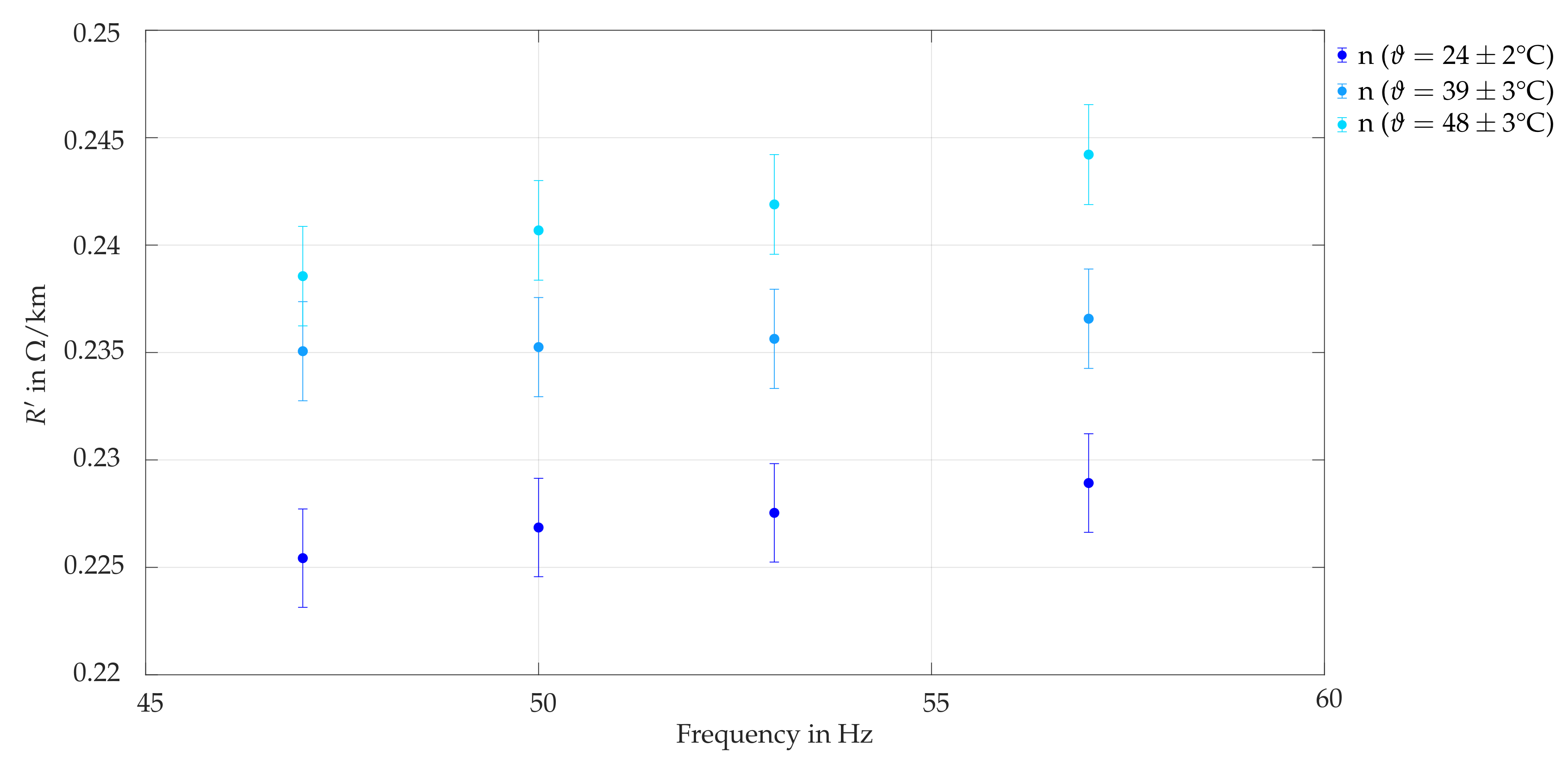
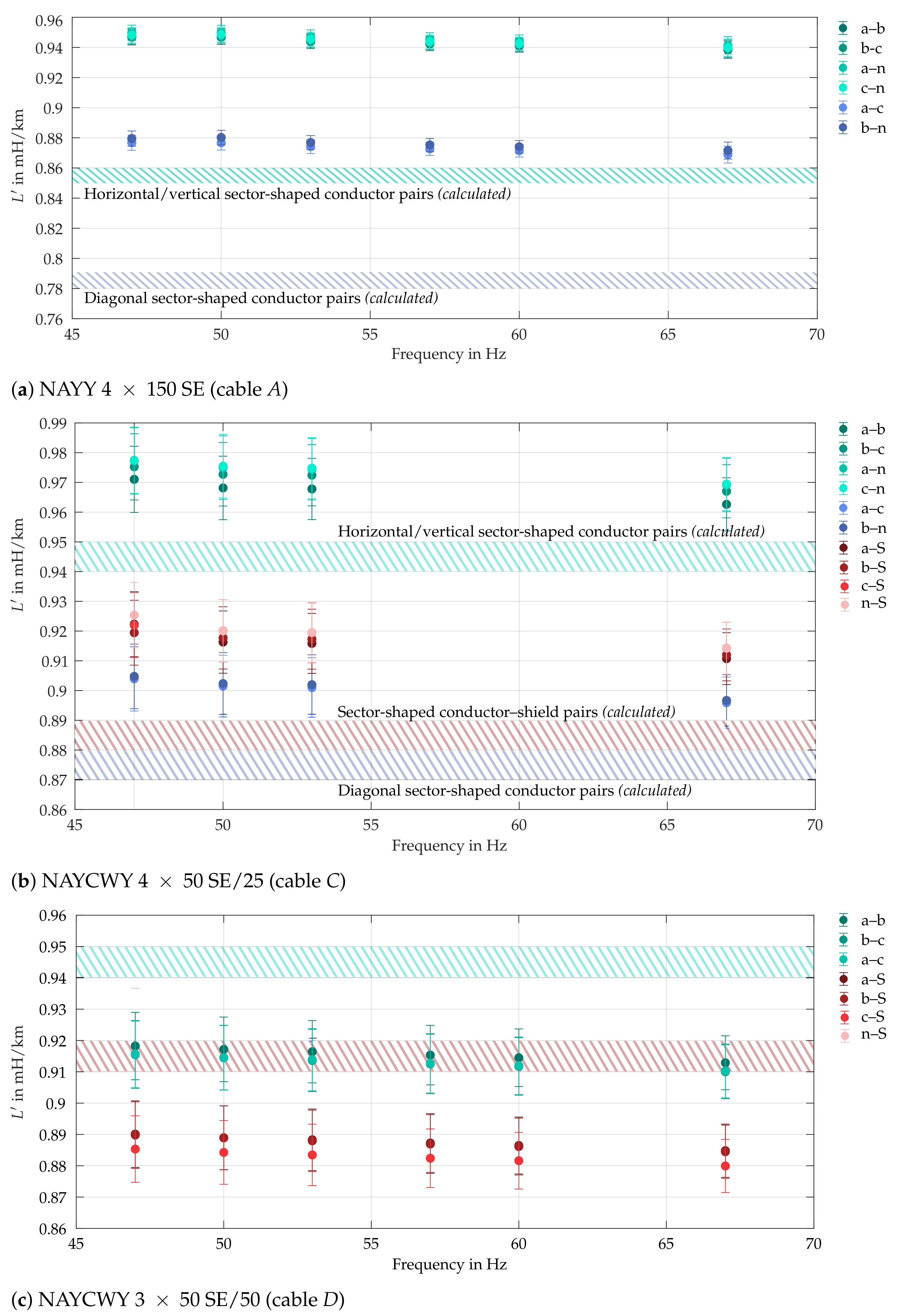

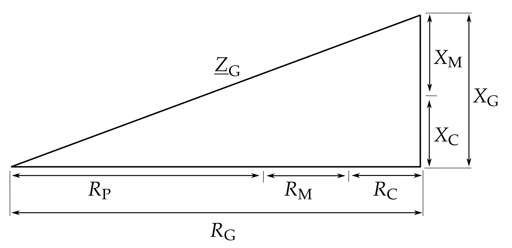

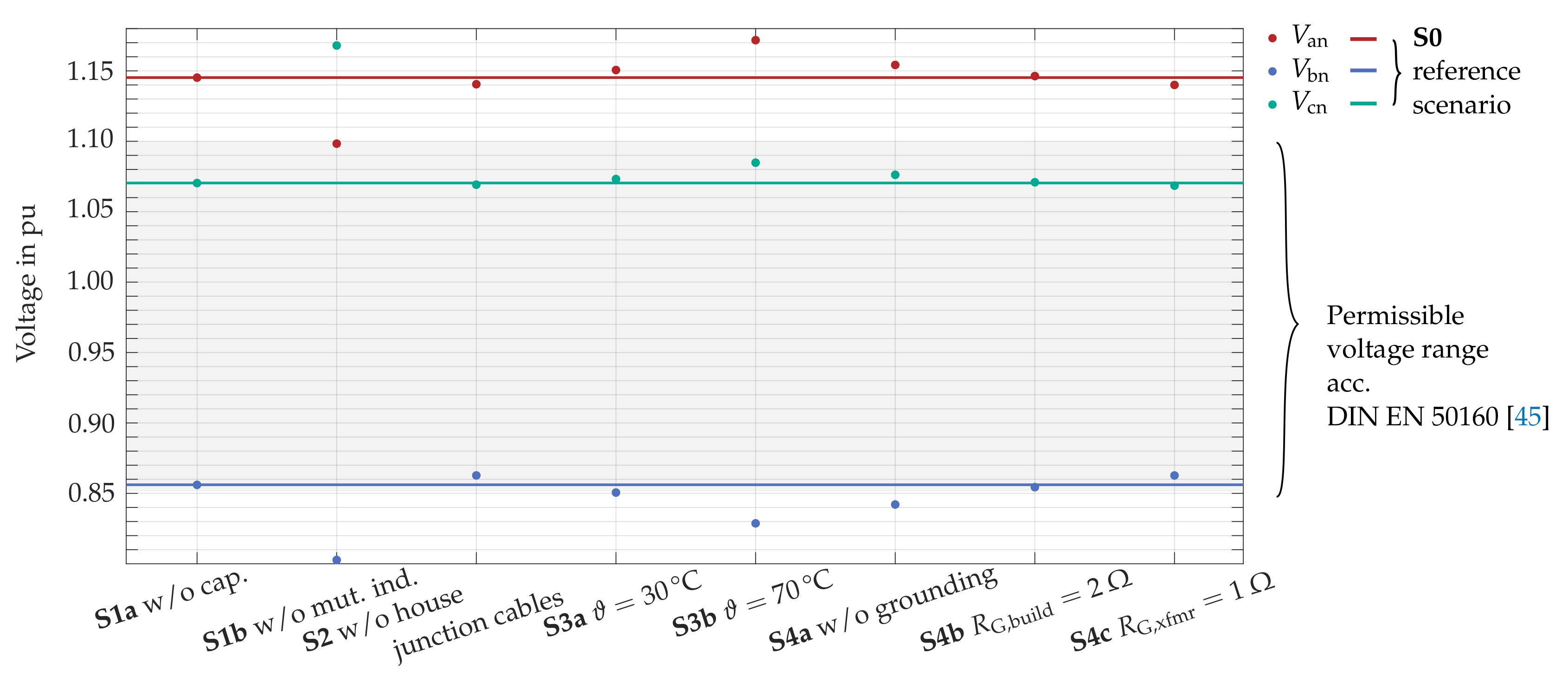

| Sub- Station | Feeder (#) | Line Type | Cabinets (∑) | Customers (∑) | Grid Type | ||||
|---|---|---|---|---|---|---|---|---|---|
| A | 1 | Cable/OL | 2 | 22 | Res. | 23.3 A | 5.43 A | 0.23 | 0.24 |
| 2 | Cable | 2 | 10 | Res. | 6.2 A | 1.19 A | 0.19 | 0.19 | |
| B | 1 | Cable | 1 | 7 | Res. | 5.6 A | 1.11 A | 0.20 | 0.30 |
| C | 1 | Cable | 1 | 1 | Ind. | 6.0 A | 3.24 A | 0.54 | 0.63 |
| 2 | Cable | 1 | 4 | Ind. | 6.9 A | 1.83 A | 0.26 | 0.29 | |
| D | 1 | Cable/OL | 0 | 8 | Res. | 8.7 A | 0.54 A | 0.06 | 0.07 |
| 2 | Cable | 1 | 14 | Res. | 16.3 A | 6.53 A | 0.40 | 0.42 | |
| 3 | Cable | 0 | 14 | Res. | 6.8 A | 2.49 A | 0.37 | 0.52 | |
| 4 | Cable | 1 | 21 | Res. | 13.4 A | 8.83 A | 0.66 | 0.93 | |
| 5 | Cable | 1 | 19 | Res. | 15.5 A | 6.18 A | 0.40 | 0.46 | |
| 6 | OL | 0 | 8 | Res. | 6.0 A | 0.94 A | 0.16 | 0.15 | |
| E | 1 | Cable/OL | 0 | 13 | Res. | 9.5 A | 2.93 A | 0.31 | 0.35 |
| 2 | Cable | 0 | 9 | Res. | 3.6 A | 0.95 A | 0.26 | 0.35 | |
| 3 | Cable/OL | 0 | 8 | Res. | 15.8 A | 1.90 A | 0.12 | 0.12 | |
| 4 | Cable | 0 | 3 | Res. | 2.4 A | 0.67 A | 0.27 | 0.26 | |
| F | 1 | Cable | 0 | 1 | Hotel | 9.5 A | 1.29 A | 0.14 | 0.19 |
| G | 1 | OL | 0 | 7 | Res. | 13.2 A | 0.77 A | 0.06 | 0.06 |
| 2 | OL | 0 | 3 | Res. | 5.7 A | 0.54 A | 0.10 | 0.10 |
| Time | ||||
|---|---|---|---|---|
| 11:23 a.m. | 6.91 A | 1.13 A | 0.16 | 0.16 |
| 11:25 a.m. | 2.24 A | 0.42 A | 0.19 | 0.19 |
| 11:39 a.m. | 2.37 A | 0.47 A | 0.20 | 0.17 |
| 12:40 p.m. | 6.24 A | 1.19 A | 0.19 | 0.19 |
| 12:43 p.m. | 3.57 A | 0.72 A | 0.20 | 0.21 |
| 12:45 p.m. | 5.59 A | 1.05 A | 0.19 | 0.21 |
| Mean | 4.49 A | 0.83 A | 0.19 | 0.19 |
| RSD | 0.45 | 0.41 | 0.08 | 0.11 |
| Sub- Station | Feeders (∑) | Customers (∑) | |||||
|---|---|---|---|---|---|---|---|
| B | 10 | 111 | 34.62 A | 34.41 A | 1.62 A | 0.05 | 0.04 |
| C | 6 | 12 | 27.41 A | 26.17 A | 1.39 A | 0.05 | 0.06 |
| D | 6 | 84 | 57.00 A | 54.01 A | 4.28 A | 0.08 | 0.07 |
| E | 6 | 48 | 52.52 A | 51.50 A | 1.05 A | 0.02 | 0.02 |
| F | 8 | 19 | 37.32 A | 37.20 A | 0.47 A | 0.01 | 0.00 |
| G | 2 | 10 | 8.39 A | 8.10 A | 0.46 A | 0.06 | 0.05 |
| H | 2 | 9 | 5.80 A | 5.10 A | 1.09 A | 0.21 | 0.20 |
| Soil Type | in m (Mean Value) |
|---|---|
| Marshy soil | 30 |
| Clay or humus soil, arable land | 100 |
| Sandy soil (humid) | 200 |
| Sandy soil (dry) | 1100 |
| Stony soil | 1000 |
| Concrete (1 part of cement, 3 parts of sand) | 150 |
| Aluminum ( 20 ) | |
| Stainless steel strip for foundation grounding | ≤ |
| Cable Type | Manufacturer | Length | |
|---|---|---|---|
| A | NAYY-J 4150 | Bayka [30] | ≈ |
| B | NAYY-J 450 | Bayka [30] | ≈ |
| C | NAYCWY 450 SE/25 | Bayka [31] | ≈ |
| D | NAYCWY 350 SE/50 | Faber [32] | ≈ |
| x | ||||||
|---|---|---|---|---|---|---|
| 0 | 50 | 0.16 | 1.0002 | 1.0004 | 1.0006 | |
| 150 | 0.28 | 1.0021 | 1.0054 | 1.0075 | ||
| 20 | 50 | 0.16 | 1.0002 | 1.0003 | 1.0005 | |
| 150 | 0.27 | 1.0018 | 1.0036 | 1.0053 | ||
| 70 | 50 | 0.14 | 1.0001 | 1.0002 | 1.0003 | |
| 150 | 0.25 | 1.0012 | 1.0025 | 1.0037 |
| Cable Type | ||||
|---|---|---|---|---|
| A | NAYY-J 4150 | 0.17 | 0.01 | – |
| B | NAYY-J 450 | 0.13 | 0.01 | – |
| C | NAYCWY 450 SE/25 | 0.11 | 0.01 | 0.22 |
| D | NAYCWY 3 50 SE/50 | 0.09–0.10 | – | 0.35 |
| Reference | Formula | Approximation Based on | Result | |
|---|---|---|---|---|
| [43] | Hemispherical grounding electrode | |||
| [41] | Soil-embedded circular ring electrode |
| Node | Base Load | PV Plant | EV |
|---|---|---|---|
| PQ Load | PQ Load | PQ Load | |
| P = + 100 W | P = − 4600 W | P = + 4600 W | |
| (ind.) | |||
| 10 | a, b, c | – | – |
| 11 | a, b, c | b | – |
| 12 | a, b, c | a | – |
| 13 | a, b, c | b | – |
| 14 | a, b, c | – | – |
| 15 | a, b, c | a | – |
| 16 | a, b, c | – | – |
| 17 | a, b, c | a | – |
| 18 | a, b, c | – | – |
| 19 | a, b, c | a | c |
| K0 | K1 | K2 | K3 | |
|---|---|---|---|---|
| a | 4PV | 4PV | 2PV | 1EV |
| b | 1EV | 2PV | 4PV | 4PV |
| c | 2PV | 1EV | 1EV | 2PV |
Publisher’s Note: MDPI stays neutral with regard to jurisdictional claims in published maps and institutional affiliations. |
© 2021 by the authors. Licensee MDPI, Basel, Switzerland. This article is an open access article distributed under the terms and conditions of the Creative Commons Attribution (CC BY) license (http://creativecommons.org/licenses/by/4.0/).
Share and Cite
Geis-Schroer, J.; Hubschneider, S.; Held, L.; Gielnik, F.; Armbruster, M.; Suriyah, M.; Leibfried, T. Modeling of German Low Voltage Cables with Ground Return Path. Energies 2021, 14, 1265. https://doi.org/10.3390/en14051265
Geis-Schroer J, Hubschneider S, Held L, Gielnik F, Armbruster M, Suriyah M, Leibfried T. Modeling of German Low Voltage Cables with Ground Return Path. Energies. 2021; 14(5):1265. https://doi.org/10.3390/en14051265
Chicago/Turabian StyleGeis-Schroer, Johanna, Sebastian Hubschneider, Lukas Held, Frederik Gielnik, Michael Armbruster, Michael Suriyah, and Thomas Leibfried. 2021. "Modeling of German Low Voltage Cables with Ground Return Path" Energies 14, no. 5: 1265. https://doi.org/10.3390/en14051265
APA StyleGeis-Schroer, J., Hubschneider, S., Held, L., Gielnik, F., Armbruster, M., Suriyah, M., & Leibfried, T. (2021). Modeling of German Low Voltage Cables with Ground Return Path. Energies, 14(5), 1265. https://doi.org/10.3390/en14051265


