Article

Finite Set Model Predictive Control of a Dual-Motor Torque Synchronization System Fed by an Indirect Matrix Converter

1
School of Electrical and Information Engineering, Tianjin University, Tianjin 300072, China
2
College of Electrical Engineering, Zhejiang University, Hangzhou 310027, China
*
Author to whom correspondence should be addressed.
Energies 2021, 14(5), 1325; https://doi.org/10.3390/en14051325
Submission received: 14 January 2021 / Revised: 21 February 2021 / Accepted: 23 February 2021 / Published: 1 March 2021
(This article belongs to the Section F: Electrical Engineering)

Abstract

:
In the dual-motor torque synchronization system fed by an indirect matrix converter (IMC), a finite set model predictive control (FCS-MPC) strategy based on a standard quadratic cost function was proposed to solve the open-loop problem of the torque synchronization error in a traditional closed-loop control strategy. Through the unified modeling of a dual-motor system, the torque synchronization error as a new state variable was involved in the switching state selection of the inverter stages, and the space vector modulation method was still used in the rectifier stage. At the same time, based on the unified prediction model, the auxiliary diagonal matrix was constructed, and the weight coefficients were solved offline by using the Lyapunov stability theory to ensure the convergence of each error term in the continuous control period. The proposed FCS-MPC strategy not only solves the problem of weight coefficient setting, but also makes it possible for a multi-motor synchronization system to expand the number of motors. The simulation and experimental results verified the effectiveness and feasibility of the control strategy. In addition, the proposed FCS-MPC strategy can ensure good torque tracking performance and synchronization performance of each motor.

Graphical Abstract

1. Introduction

An indirect matrix converter (IMC) contains an independent rectifier stage and an inverter stage in terms of topology. Different modulation strategies can be applied to modulate each part, respectively. In addition, it can realize the zero-current commutation of bidirectional switches, and the control strategy is very flexible [1,2,3]. In an AC speed regulation system, due to its special topology, an IMC can use the dc-link as the bus to connect multiple inverter stages to drive multiple AC loads. Its clamping circuit is simple, only one diode and one small capacity capacitor are needed, which makes the circuit structure more compact and more integrated, and it has great advantages in industrial applications [4,5]. In heavy-duty industrial applications, such as high-power traction systems, mining shield equipment and ship propulsion systems, due to the large output torque, one load is usually required to be driven by multiple motors, and the output torque of each motor should be balanced. However, due to the uncertainty of working conditions and the difference of motor parameters in the system, the torque fluctuation of the motor will be caused, which will affect the torque synchronization performance of the system, and even the shaft break and other accidents will occur in serious cases [6,7]. Therefore, it is of great significance to study the torque synchronization strategy of a dual-motor system fed by an IMC for the safe production of heavy-duty industrial applications [8,9].
Scholars at home and abroad have achieved a series of research results on multi-motor drive systems based on an IMC [10]. In [1], the topology of a multi-motor drive system based on an IMC was proposed. In [3], the vector control was combined with a multi-drive system based on a two-stage matrix converter for driving two motors on the same shaft, and the coaxial speed and output current of two induction motors with the same parameters were simulated and analyzed. In [11], a dual-motor system fed by an IMC was proposed, in which multiple induction motors with different parameters were controlled independently, which increased the flexibility of the system.
In view of the limited research on the torque synchronization control strategy of the dual-motor system fed by an IMC at home and abroad, and the open-loop problem of the torque synchronization error in the traditional closed-loop control strategy based on the master-slave structure, this paper considered the combination of the dual-motor system and the finite set model predictive control strategy, which can not only meet the needs of multi-objective control, but also give full play to the advantages of a dual-motor system fed by an IMC in industrial applications. The finite set model predictive control (FCS-MPC) strategy applies a discrete-time system mathematical model to predict the effect of each switching state one by one within a limited control period, and finally selects the optimal switching state [12,13,14,15]. Compared to field-oriented control (FOC) and direct torque control (DTC), FCS-MPC predicts, evaluates, and optimizes the future impact of all switching states separately, which is more conducive to achieving multi-objective control of the system and is more suitable for a dual-motor synchronization control system [16,17,18,19].
For the dual-motor torque synchronization system fed by an IMC in this paper, the control variables include both the current tracking error of each motor and the torque synchronization error of the dual-motor. There are at least three weight coefficients which need to be set. The empirical setting method does not only rely on subjective experience, but also increases the complexity of system design due to a large number of comparative experiments. The weight coefficients obtained after setting can improve the control performance of the system to a certain extent, but the optimal solution of the control objective cannot be obtained [20]. In [21], a quadratic form of cost function was proposed. Its characteristic is that the control variables are included in the error vector, and there is only one weight coefficient matrix in the cost function. The offline solution process of the weight coefficient matrix is independent of the number of control variables. In this paper, the concept of quadratic cost function in [21] was used to solve the torque synchronization problem of the dual-motor system fed by an IMC. Different from the solution in [21], this paper simplified the lengthy quadratic cost function into a standard quadratic cost function, and the offline solution algorithm based on the Lyapunov stability principle is used to realize the self-tuning of the proposed auxiliary diagonal weight coefficient matrix so as to ensure the convergence of each error term and the asymptotic stability of the system, which significantly reduces the complexity and workload of system design.
This paper is organized as follows. The topology of the dual-motor system fed by an IMC and the analysis of the tracking error and synchronization error based on the traditional closed-loop control strategy based on the master-slave structure are presented in Section 2. The unified prediction model of the dual-motor system along with the cost function of standard quadratic form and the solving process of the weighting matrix are described in Section 3. Through the simulation and experimental results, the feasibility of the proposed strategy will be demonstrated in Section 4 and Section 5. Some conclusions are given in the last section.

2. Closed-Loop Control Strategy for Dual-Motor Torque Synchronization System Fed by an IMC

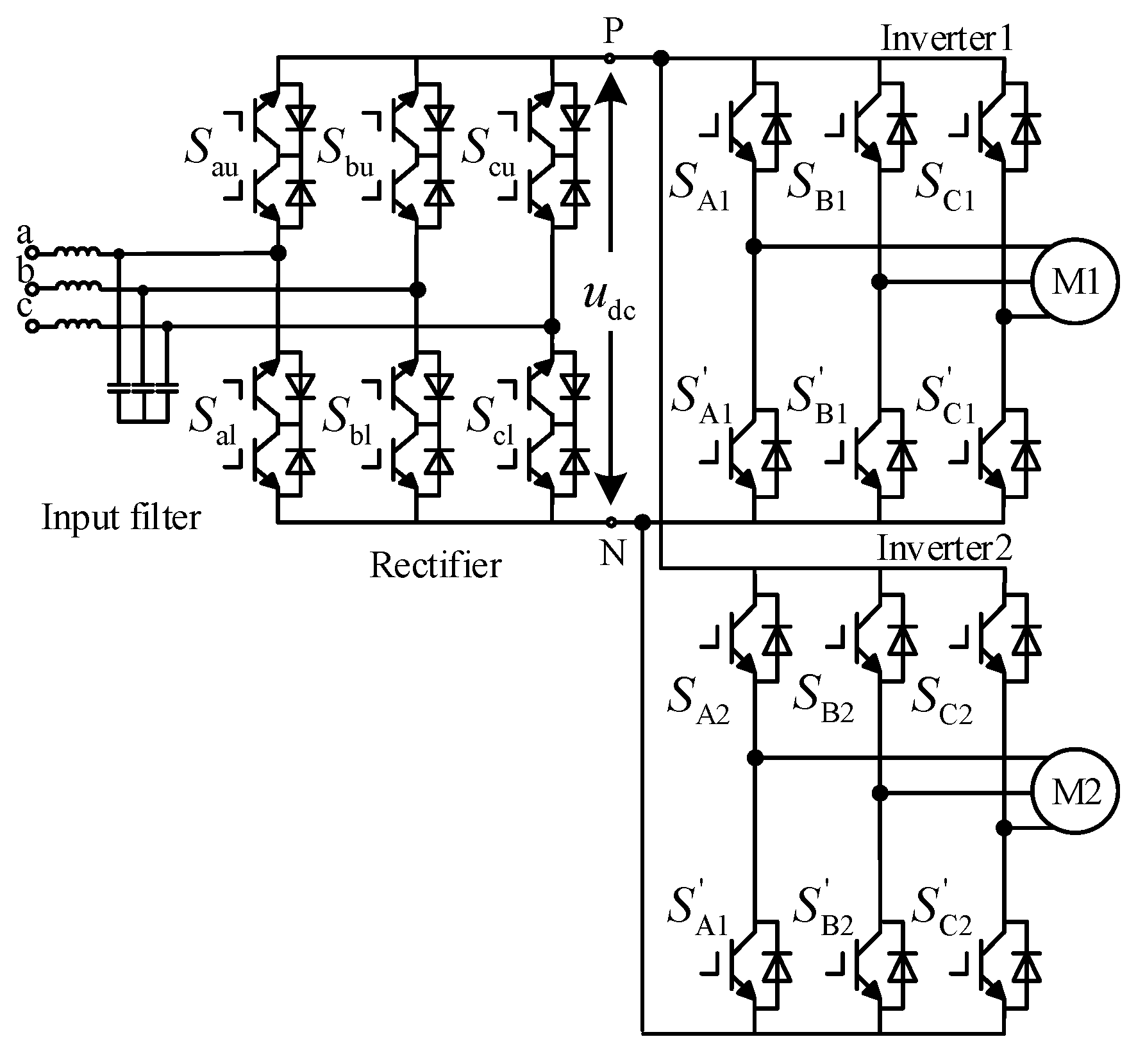
2.1. Topology of Dual-Motor System Fed by an IMC

The IMC adopts the AC-DC-AC dual-stage conversion structure, which is composed of a three-phase AC input power supply, an input filter, a rectifier stage circuit, an inverter stage and two permanent magnet synchronous motors (PMSMs). Its topology is shown in Figure 1. The rectifier stage consists of six bi-directional switches Smn (m = a,b,c for three-phase bridge arm; n = u,l for upper and lower bridge arms, respectively). The two inverter stages are the same as the traditional voltage source inverter. The dc-link of the IMC can be connected to multiple inverter stages to drive multiple AC loads.
The control block diagram of the dual-motor system fed by an IMC is shown in Figure 2. In the figure, ω * represents the reference value of motor speed. The control system consists of a rectifier stage controller, an inverter stage controller, and a speed controller. The two motors of the system drive the same load through a coaxial rigid connection.

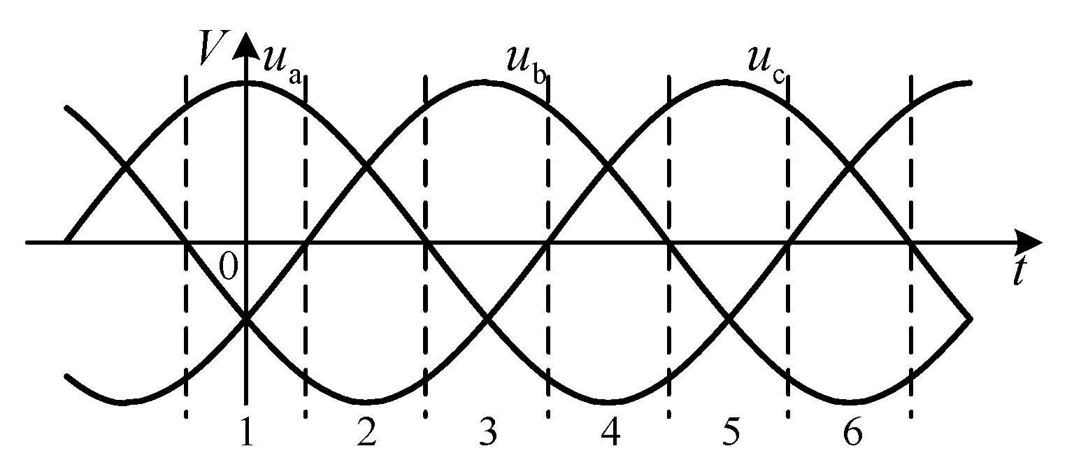
2.2. Space Vector Modulation Strategy for Rectifier Stage

To make the dc-link voltage polarity positive, the utilization rate of voltage is maximum, the grid side is controlled by a unity power factor, and the rectifier stage of an IMC usually adopts space vector pulse width modulation (SVPWM) without a zero vector. Therefore, according to the method shown in Figure 3, the input voltage interval is divided equally according to the zero-crossing point of the input phase voltage, each interval accounts for π/3 electrical angle, and each interval is called a sector.
In the unit switching period, the dc-link of the rectifier stage outputs two relatively large line voltages with positive polarity according to a certain duty cycle. The switching status and duty ratio of the rectifier stage in six sectors are shown in Table 1.

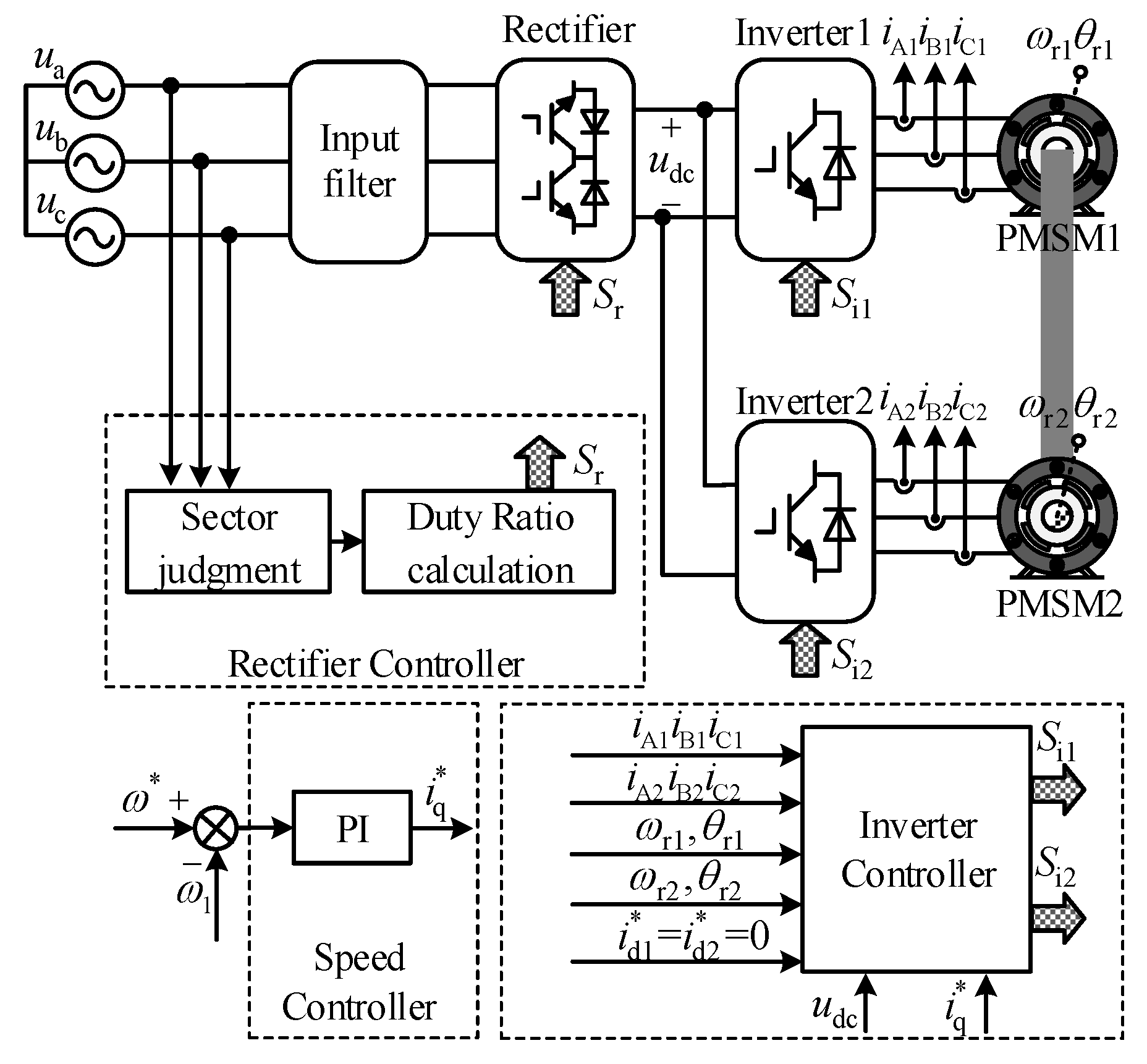
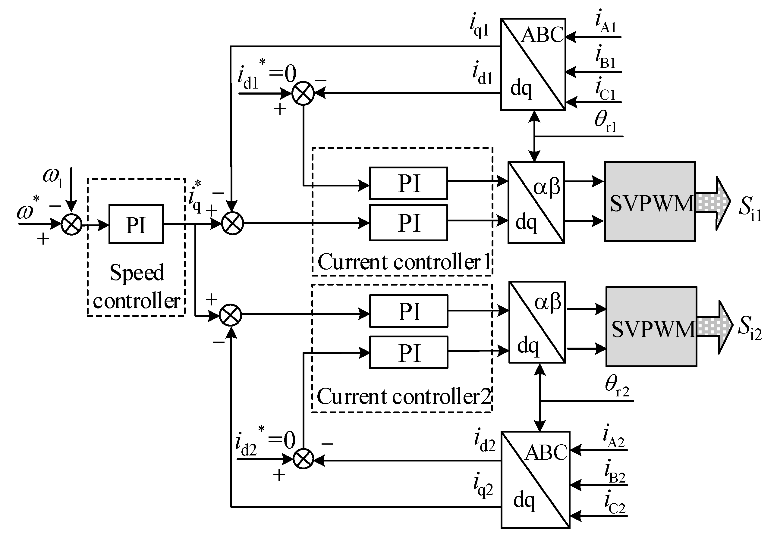
2.3. Closed-Loop Control Strategy Based on Master-Slave Structure

The inverter stage controller of an IMC based on the master-slave structure is composed of the speed outer loop controller and the current inner loop controllers of the dual-motor, as shown in Figure 4. In the figure, ABC represents the three-phase stationary coordinate system. Regarding motor 1 as the master motor, its speed error passes through the proportional-integral (PI) regulator to produce a common q-axis current reference value i q * for the dual-motor. The current inner loop controllers of the dual-motor are independent of each other, and the vector control with id = 0 is adopted.
In the d-q axis rotating coordinate frame, the voltage equations of the i-th (i = 1,2) surface permanent magnet synchronous motor (SPMSM) are given by
{ d i d i d t = R s i L d i i d i + ω r i i q i + u d i L d i d i q i d t = R s i L q i i q i ω r i i d i + u q i L q i ψ f i ω r i L q i ,
where Ldi and Lqi are the d-axis and the q-axis stator inductances, and Ldi = Lqi = Li. udi and uqi are the d-axis and the q-axis stator voltages. Rsi, ψfi, and ωri denote stator resistance, flux linkage, and rotor electrical speed, respectively. In ωri = piωi, ωi is the rotor mechanical speed, and pi is the pole-pairs number of the motor.
The electromagnetic torque equation of the i-th motor is
T e i = 3 2 p i ψ f i i q i .
Define the torque synchronization error δ as
δ = T e 1 T e 2 = 3 2 ( p 1 ψ f 1 i q 1 p 2 ψ f 2 i q 2 ) .
Dividing both sides of Equation (3) by p1ψf1 produces
δ p 1 ψ f 1 = 3 2 ( i q 1 β i q 2 ) ,
where β = p 2 ψ f 2 p 1 ψ f 1 .
From Equation (4), the q-axis current synchronization error ε can be defined as
ε = i q 1 β i q 2 .
It is observed that the torque synchronization error of the dual-motor is proportional to the q-axis current synchronization error. Therefore, the torque synchronization control can be converted to the q-axis current synchronization control.
The change rate of the q-axis current synchronization error is
d ε d t = ( R s 1 L d 1 i q 1 ω r 1 i d 1 + u q 1 L q 1 ψ f 1 ω r 1 L q 1 ) β ( R s 2 L d 2 i q 2 ω r 2 i d 2 + u q 2 L q 2 ψ f 2 ω r 2 L q 2 ) .
In the dual-motor system with a coaxial rigid connection, the mechanical connection makes the speed of the dual-motor strictly synchronous, that is, ωr1 = ωr2 = ωr. Substituting ωr into Equation (6) produces
d ε d t = ( β R s 2 L d 2 i q 2 R s 1 L d 1 i q 1 ) + ( u q 1 L q 1 β u q 2 L q 2 ) ω r ( β i d 2 i d 1 ) + ω r ( β ψ f 2 L q 2 ψ f 1 L q 1 ) .
Equation (7) shows that the differences in permanent magnet flux linkage, resistance, inductance, q-axis voltage, d-axis current and q-axis current of the two motors will affect the q-axis current synchronization error of the system.
The dual-motor torque synchronization system fed by an IMC based on the master-slave structure makes the speed of two motors forced synchronization through mechanical connection, and the current inner loop controllers make the q-axis current of each motor track the same given value, to make the q-axis current synchronous, and then realize the torque synchronization control of the dual-motor. However, the current inner loop controllers of the dual-motor are independent of each other, and the q-axis current synchronous control of the system does not establish a connection between the inner loop controllers. In other words, the synchronous control of the q-axis current (torque synchronous control) is an open-loop control, and because the mechanical time constant is much greater than the electrical time constant, there are differences in resistance and inductance parameters between the motors, and the master and slave motors are mechanically connected. The torque synchronization error cannot be quickly reflected to the inner loop controller of each motor, and the torque synchronization performance and anti-interference performance of the system are not ideal. Therefore, the inverter controller of an IMC based on an FCS-MPC structure is designed, and the coupling relationship between two motors is added in the inner loop controllers to further improve the torque synchronization performance.

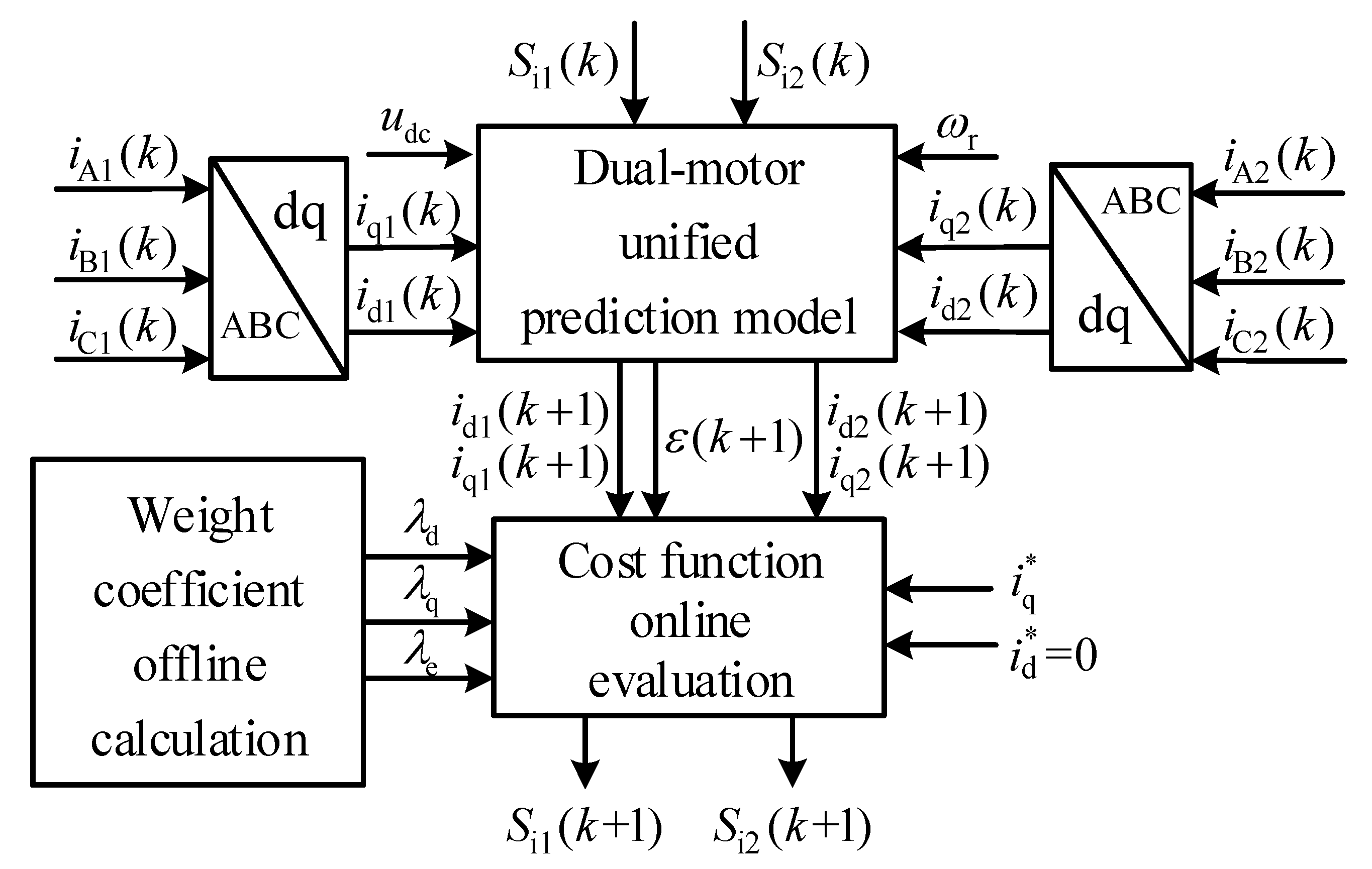
3. FCS-MPC Strategy for Dual-Motor Torque Synchronization System Fed by an IMC

The inverter stage controller based on the FCS-MPC structure proposed in this paper is shown in Figure 5. It is mainly composed of the dual-motor unified prediction model, the online evaluation unit of the cost function and the offline calculation unit of the weight coefficients.

3.1. Unified Prediction Model of Dual-Motor

In order to achieve closed-loop control of the torque synchronous error, the unified model is established. Considering the two motors and the IMC as a whole, the synchronization error is introduced in the predictive control as one of the state variables.
Through Euler discretization of Equation (1), the predictive values of the d-axis and the q-axis stator currents at (k + 1)Ts are obtained as follows:
{ i d i ( k + 1 ) = A i i d i ( k ) + B i ( k ) i q i ( k ) + C i u d i ( k ) i q i ( k + 1 ) = A i i q i ( k ) B i ( k ) i d i ( k ) + C i u q i ( k ) D i ( k ) ,
where Ai = 1 − TsRsi/Li; Bi(k) = Tsωri(k); Ci = Ts/Li; Di(k) = Tsωri(k)ψfi/Li; Ts is the sampling period.
The input voltage of the i-th motor is
[ u d i ( k ) u q i ( k ) ] = E i ( k ) u o i ( k ) ,
in which Ei(k) is the transfer matrix from the ABC coordinate frame to the d-q axis rotating coordinate frame. It is given by
E i ( k ) = 2 3 [ cos θ i cos ( θ i 2 π / 3 ) cos ( θ i + 2 π / 3 ) sin θ i sin ( θ i 2 π / 3 ) sin ( θ i + 2 π / 3 ) ] ,
where θi is the angle between the rotor magnetic pole axis and the A-phase stator winding axis, and it represents the position of the rotor variable.
In this paper, an IMC is used to supply power for two PMSMs. The output phase voltage uoi(k) is
u o i ( k ) = u dc ( k ) 3 [ 2 1 1 1 2 1 1 1 2 ] [ S A i ( k ) S B i ( k ) S C i ( k ) ] ,
in which the dc-link voltage udc(k) is
u dc ( k ) = [ S au ( k ) S al ( k ) S bu ( k ) S bl ( k ) S cu ( k ) S cl ( k ) ] T [ u a u b u c ] ,
where SAi, SBi, and SCi are the switching states of the upper arm of the inverter stages. Sau, Sal, Sbu, Sbl, Scu, and Scl are the switching states of the bi-directional switches of the upper and lower arms of the rectifier stage. The value of “1” indicates that the switch is on, the value of “0” indicates that the switch is off, and the driving signals of the upper and lower arms are complementary.
Taking the d-axis currents, the q-axis currents and the q-axis current synchronization error of the dual-motor as state variables, and given the time delay compensation, the unified prediction model is presented as:
X ( k + 2 ) = G ( k + 1 ) × X ( k + 1 ) + F × U ( k + 1 ) + K × D ( k + 1 ) ,
in which X(k + 1) = [id1(k + 1) iq1(k + 1) id2(k + 1) iq2(k + 1) ε(k + 1)]T, U(k + 1) = [ud1(k + 1) uq1(k + 1) ud2(k + 1) uq2(k + 1)]T, D(k + 1) = [D1(k + 1) D2(k + 1)]T,
G ( k + 1 ) = [ A 1 B 1 ( k + 1 ) 0 0 0 B 1 ( k + 1 ) A 1 0 0 0 0 0 A 2 B 2 ( k + 1 ) 0 0 0 B 2 ( k + 1 ) A 2 0 B 1 ( k + 1 ) 0 β B 2 ( k + 1 ) β ( A 1 A 2 ) A 1 ] , F = [ C 1 0 0 0 0 C 1 0 0 0 0 C 2 0 0 0 0 C 2 0 C 1 0 β C 2 ] , K = [ 0 0 1 0 0 0 0 1 1 β ] ,
where Bi(k + 1) = Tsωri(k + 1), Di(k + 1) = Tsωri(k + 1)ψfi/Li.
The FCS-MPC strategy obtains the current value at kTs, and obtains the predicted current values idi(k + 2), iqi(k + 2), and the predicted current synchronization error ε(k + 2) of the dual-motor at (k + 2)Ts under each switching state combination by using Equation (11). The predicted values and weight coefficients λd, λq, and λe are substituted into the cost function for online evaluation, and the optimal switching state combination is selected from 64 alternative switching states as the input of inverter stages at (k + 1)Ts.

3.2. Cost Function of FCS-MPC Strategy

The cost function of the dual-motor torque synchronization system is
g ( k ) = λ d g d ( k ) + λ q g q ( k ) + λ e g e ( k ) ,
{ g d ( k ) = | i d 1 * i d 1 ( k + 2 ) | 2 + | i d 2 * i d 2 ( k + 2 ) | 2 g q ( k ) = | i q 1 * i q 1 ( k + 2 ) | 2 + | i q 2 * i q 2 ( k + 2 ) | 2 g e ( k ) = | ε ( k + 2 ) | 2 = | i q 1 ( k + 2 ) β i q 2 ( k + 2 ) | 2 ,
where gd, gq, and ge are the d-axis, the q-axis current tracking error and the q-axis current synchronization error, respectively; λd, λq, and λe are the weight coefficients of corresponding errors in the cost function; i d 1 * , i d 2 * , i q 1 * , and i q 2 * are the d-axis and the q-axis current references, respectively.

3.3. Auxiliary Diagonal Matrix

The empirical setting method relies on subjective experience and requires a lot of comparative tests. In that way, only the value range can be obtained approximately and the optimal weight coefficients are unable to be determined accurately. Therefore, an algorithm for solving weight coefficients based on an auxiliary diagonal matrix is proposed in this paper.
The quadratic polynomial is defined as
H ( e ) = m 11 e 1 2 + m 22 e 2 2 + m 33 e 3 2 + m 44 e 4 2 + m 55 e 5 2 .
The quadratic form with only square term is called the standard form of quadratic form, and the matrix form in discrete state is obtained as follows
H ( k ) = e T ( k + 2 ) M e ( k + 2 ) ,
where
M = diag ( m 11 m 22 m 33 m 44 m 55 ) ,
e = [ e 1 e 2 e 3 e 4 e 5 ] T ,
in which M is the 5th order diagonal matrix corresponding to quadratic polynomial H(e). e is the 5 × 1-dimensional error vector, including current tracking errors and the synchronization error of the dual-motor, where e1 = id1*id1(k + 2), e2 = iq1*iq1(k + 2), e3 = id2*id2(k + 2), e4 = iq2*iq2(k + 2), and e5 = ε(k + 2).
According to the related theorems of the Lyapunov stability theory, if there is a diagonal matrix M, H(k) is positive definite and monotonically decreasing, then H(k) is a Lyapunov function. Therefore, when H(k) is a Lyapunov function, the optimal vector which minimizes the cost function g(k) can be selected in the process of model prediction. If an auxiliary diagonal matrix M can be constructed to ensure that H(k) has H(k) > 0 and H(k) < H(k − 1) in the continuous control period, then the error vector e (current synchronization error and tracking errors) converges to zero and the cost function g(k) also tends to zero.
The diagonal elements m11, m22, m33, m44 and m55 of M are coefficients of (id1*id1(k + 2))2, (iq1*iq1(k + 2))2, (id2*id2(k + 2))2, (iq2*iq2(k + 2))2, and (ε(k + 2))2, respectively. When two PMSMs with same parameters are used in the system, λd = m11 = m33, λq = m22 = m44, λe = m55. The matrix M is solved below.

3.4. Diagonal Matrix Offline Algorithm

In the steady state, X(k + 2) = X(k) = X*, the steady-state model of the system is obtained as follows:
X * = G ( k + 1 ) × X * + F × U ( k + 1 ) + K × D ( k + 1 ) .
Subtract Equations (20) and (13) to obtain
e ( k + 2 ) = G ( k + 1 ) × e ( k + 1 ) ,
H ( k ) H ( k 1 ) = e T ( k + 2 ) M e ( k + 2 ) e T ( k + 1 ) M e ( k + 1 ) = e T ( k + 1 ) ( G T ( k + 1 ) M G ( k + 1 ) M ) e ( k + 1 ) .
If H(k) satisfies H(k) > 0 and H(k) < H(k − 1) in the continuous control period, then
M G T ( k + 1 ) M G ( k + 1 ) > 0 ,
Multiplying both sides of Equation (23) with M−1 produces
M 1 M 1 G T ( k + 1 ) M G ( k + 1 ) M 1 > 0 .
According to the related properties of the matrix Schur complement, the left side of Equation (24) is defined as the Schur complement of W with respect to M−1, where
W = [ M 1 M 1 G T ( k + 1 ) M 1 G ( k + 1 ) M 1 ] .
The related lemmas of Schur’s complement theorem are known: if M−1 is reversible, then the Schur’s complements of M−1 and W are both positive definite and can be equivalent to W positive definite. Therefore, the following linear matrix inequality (LMI) is obtained:
W = [ M 1 M 1 G T ( k + 1 ) G ( k + 1 ) M 1 M 1 ] > 0 .
The solution of Equation (26) can ensure that H(k) > 0 and H(k) < H(k − 1), so that the error vector e converges. However, Equation (26) may solve more than one solution, so the selective condition of constructing M ensures that the obtained M is unique, let
M opt = max M   y ( M ) ,
where
{ y ( M ) = m 55 trace ( M ) trace ( M ) = m 11 + m 22 + m 33 + m 44 + m 55 ,
in which y(M) is a function of M. Equation (28) indicates that in the M obtained to ensure the convergence of the error vector, selecting Mopt can make the torque synchronization error account for the largest possible proportion of the weight coefficients distribution. On the basis of maintaining good tracking performance of the motor, the torque synchronization performance of the system is further improved. Either Mopt or other M can ensure that H(k) is a Lyapunov function, thereby ensuring the convergence of the error vector. Mopt is just to further highlight the role of the torque synchronization error when the cost function evaluates the candidate vectors. The solution of Mopt does not require the collection of motor parameters in every control period. Instead, the LMI toolbox in MATLAB can be used for offline calculation efficiently, avoiding the tedious procedures of manually tuning weight factors, greatly reducing the computational burden of the system and reducing the complexity of the experiment.

4. Simulation Results

To preliminarily verify the effectiveness of the proposed FCS-MPC strategy, a simulation model of the dual-motor coaxial system fed by an IMC is established based on MATLAB/Simulink. The system sampling period is 100 μs, the speed reference is 200 r/min, and the parameters of two SPMSMs for simulation are shown in Table 2.
Under the given simulation conditions, the auxiliary diagonal matrix Mopt is obtained:
M opt = [ 1.6095 0 0 0 0 0 1.6037 0 0 0 0 0 1.6095   0 0 0 0 0 1.6037 0 0 0 0 0 3.6055 ]
Mopt is applied to the proposed FCS-MPC strategy, and the traditional closed-loop control strategy and the proposed FCS-MPC strategy are simulated and compared under the conditions of no deviation and deviation in the parameters.

4.1. Simulation Results without Parameter Deviation

To compare the control effect of the two strategies, the following simulations are designed when the inductance or resistance parameters of the dual-motor have no deviation.
(1) The total load torque is set to 10 N·m and 20 N·m, respectively. The comparison of the simulation results under the two control strategies is shown in Figure 6.
It can be seen from Figure 6 that when the speed reference is constant and the load torque is different, with the increase in load torque, the torque synchronization error under the closed-loop control strategy increases from ±1.9 N·m to ±2.3 N·m. Under the proposed FCS-MPC strategy, the increasing trend of the torque synchronization error is significantly suppressed, and the torque synchronization error is controlled within ±1.6 N·m.
(2) The initial total load torque is set to 10 N·m, and the total load torque stepped to 20 N·m at 0.5 s. The comparison of the simulation results under the two control strategies is shown in Figure 7.
It can be seen from Figure 7 that under the two control strategies, the output torque of a single motor is 50% of the load torque, but compared with the traditional closed-loop control strategy, the torque synchronization error of the proposed FCS-MPC strategy has no obvious fluctuation during the load mutation process, and the torque synchronization error is controlled within ±1.6 N·m. The simulation results indicate that the proposed FCS-MPC strategy can significantly improve the torque synchronization performance of the system while ensuring the better dynamic and steady-state tracking performance of each motor.
(3) The initial total load torque is 10 N·m, and the load torque disturbance with a magnitude of 10 N·m and a duration of 0.01 s is suddenly added at 0.5 s. The comparison of the simulation results under the two control strategies is shown in Figure 8.
It can be seen from Figure 8 that compared with the simulation results of the closed-loop control strategy, the proposed FCS-MPC strategy can shorten the recovery time of the system to load torque disturbance, and on the premise of reducing the torque synchronization error, it can suppress the torque synchronization error fluctuation of the system during the disturbance process.

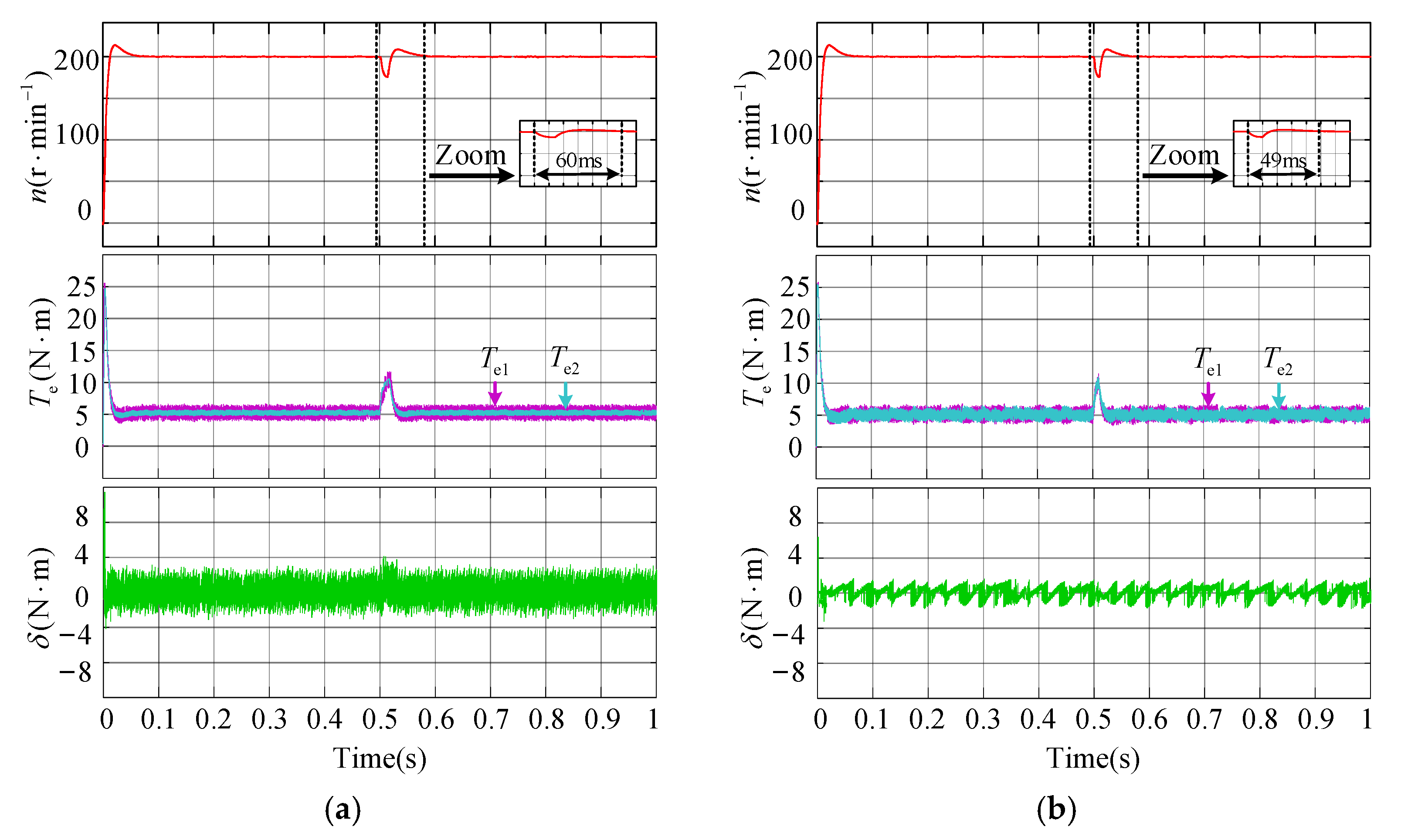
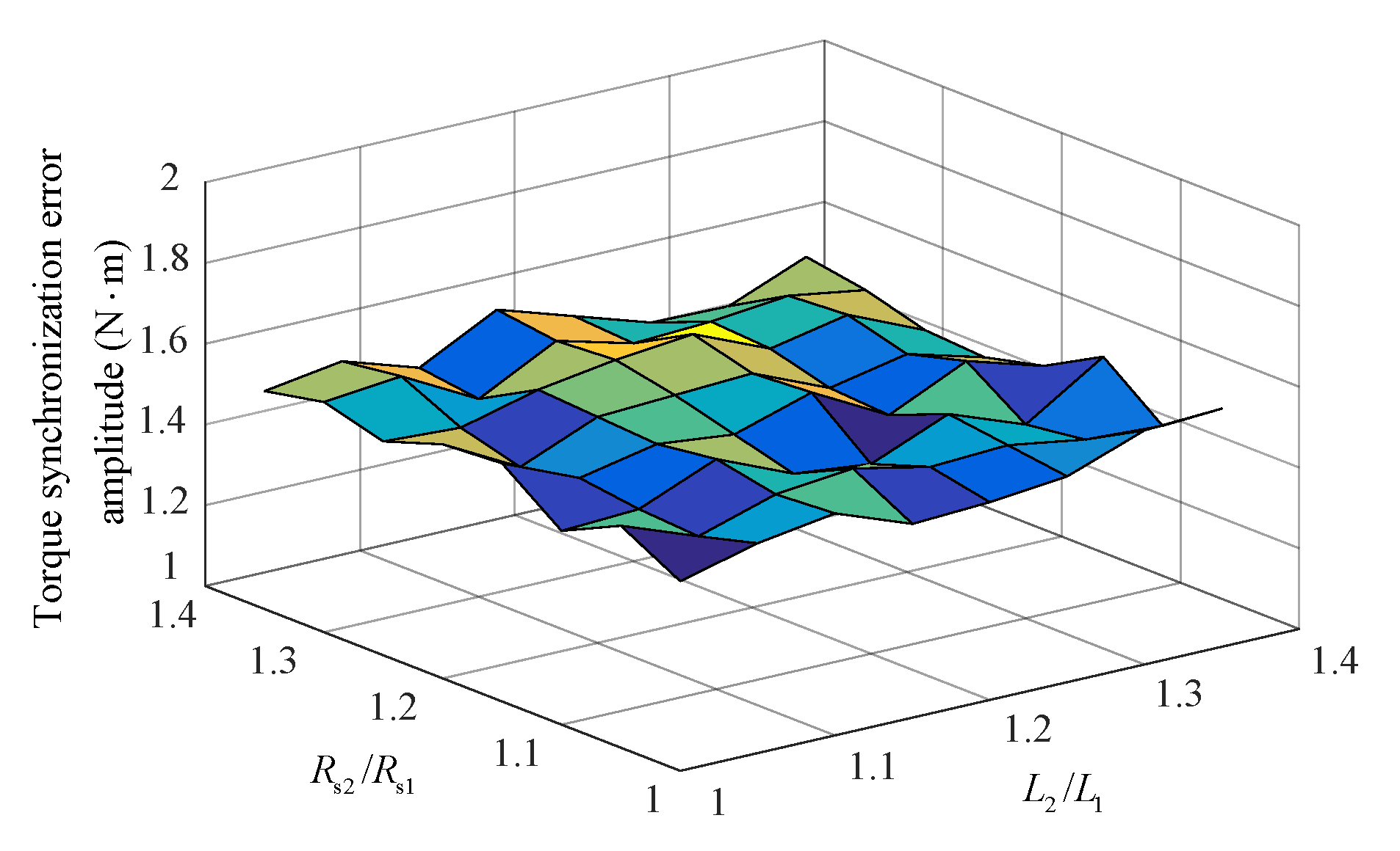
4.2. Simulation Results with Parameter Deviation

To explore the parameter robustness of the proposed FCS-MPC strategy, the simulation analysis is carried out when the resistance and inductance parameters of the dual-motor have deviations, respectively. Assuming that the parameters of motor 1 are nominal parameters and the parameters of motor 2 have deviation, Rs2/Rs1 = 1.3 and L2/L1 = 1.3 are set, and the following simulation conditions are designed:
(1) The total load torque is set to 10 N·m, and the comparison between the transient and steady-state simulation results of the system under the two control strategies is shown in Figure 9.
It can be seen from Figure 9a that under the closed-loop control strategy, the steady-state torque synchronization error is within ±2.8 N·m, and the torque synchronization error is relatively large during the starting process. It can be seen from Figure 9b that under the proposed FCS-MPC strategy, the torque synchronization error is significantly suppressed during the starting process, and the steady-state torque synchronization error is controlled within ±1.6 N·m.
(2) The initial total load torque is 10 N·m, and the load torque disturbance with a magnitude of 10 N·m and a duration of 0.01 s is suddenly added at 0.5 s. The comparison of the simulation results under the two control strategies is shown in Figure 10.
It can be seen from Figure 10a that under the closed-loop control strategy, the steady-state torque synchronization error is within ±2.8 N·m, and the torque synchronization error fluctuates to a certain extent during the disturbance process. In addition, the recovery time of the system to load torque disturbance is 60 ms. It can be seen from Figure 10b that under the proposed FCS-MPC strategy, the steady-state torque synchronization error is controlled within ±1.6 N·m, and the torque synchronization error fluctuation is significantly suppressed during the disturbance process. Moreover, the recovery time of the system to the load torque disturbance is 49 ms, which is 11 ms shorter than Figure 10a. The simulation results show that the proposed FCS-MPC strategy can significantly improve the anti-interference performance of the system.
(3) To explore the steady-state synchronous control effect with different inductance and resistance, the total load torque is set to 10 N·m. Taking the steady-state torque synchronization error amplitude of the system as the z-axis, the deviation of inductance as the x-axis, and the deviation of resistance as the y-axis, the simulation results are shown in Figure 11.
It can be seen from Figure 11 that under the proposed FCS-MPC strategy, the steady-state torque synchronization error of the system is controlled within ±1.6 N·m, the deviation of the resistance and inductance parameters within a certain range has little effect on the torque synchronization error of the system, and the controller has good parameter robustness.

5. Experimental Results

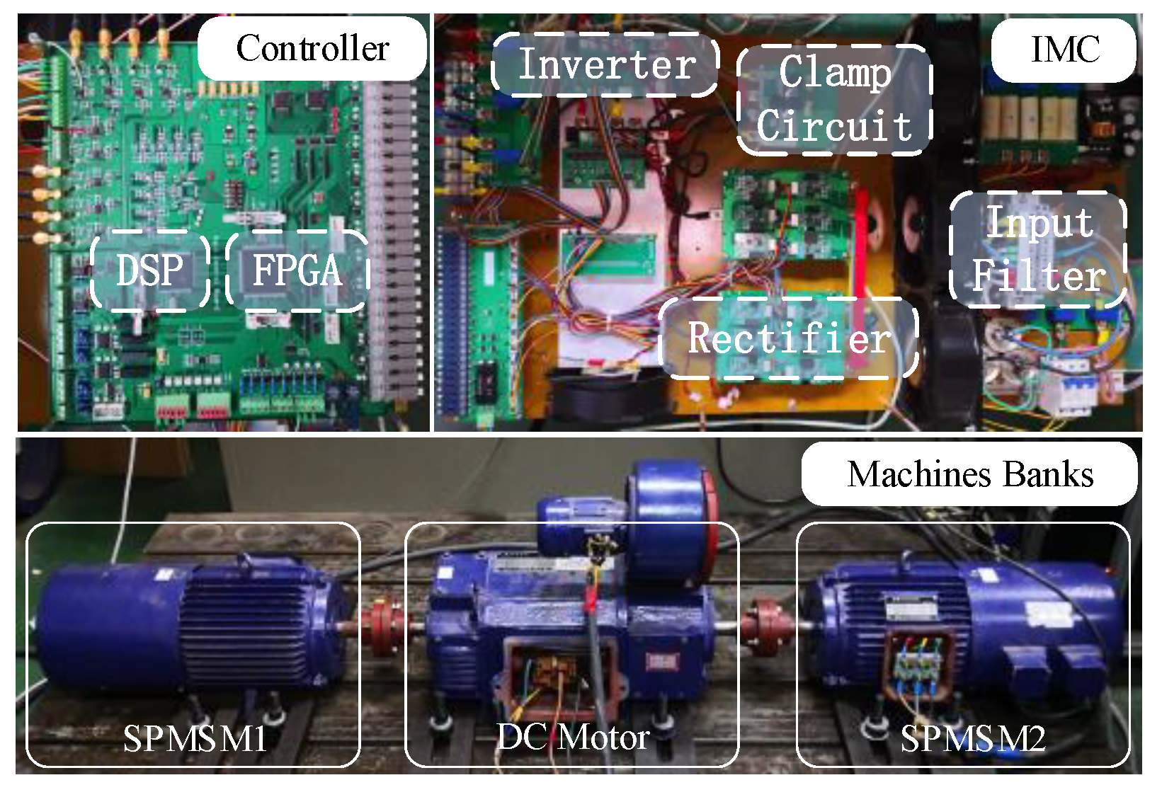
5.1. Experimental Platform

To verify the feasibility and the effectiveness of the proposed FCS-MPC strategy based on the standard quadratic cost function, an experimental platform, shown in Figure 12, was built. The digital controller of the platform consists of a DSP (TI TMS320F28335) and an FPGA (Altera EP1C6Q240C8N), and the system sampling time is 200 μs. Two SPMSMs of the same model are coaxially rigidly connected with a dual-axis DC motor, and therefore the speed is forced to be synchronized. The closed-loop control strategy based on the master-slave structure and the proposed FCS-MPC strategy based on the standard quadratic cost function have been experimentally studied. Compared with the simulation, the ability of the actual experimental system to drag the load is limited. The no-load back electromotive force (EMF) of the two SPMSMs in the experimental platform at different speeds is detected, and the permanent magnetic flux linkage value is calculated. The results show that the flux linkage of the two SPMSMs is approximately equal to the nominal value, which can be considered as β = 1. The main parameters of SPMSMs are listed in Table 2.

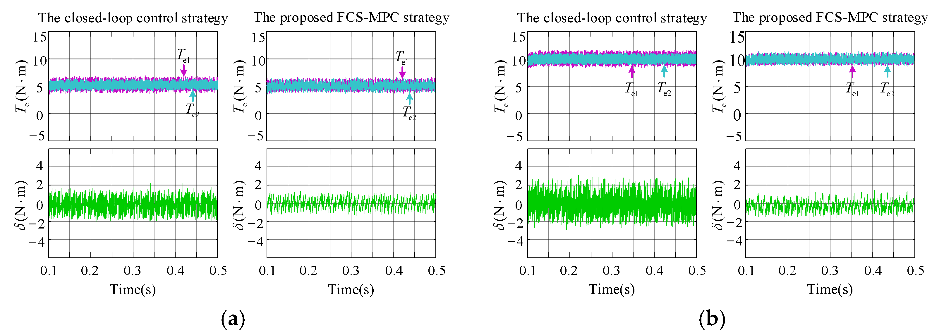
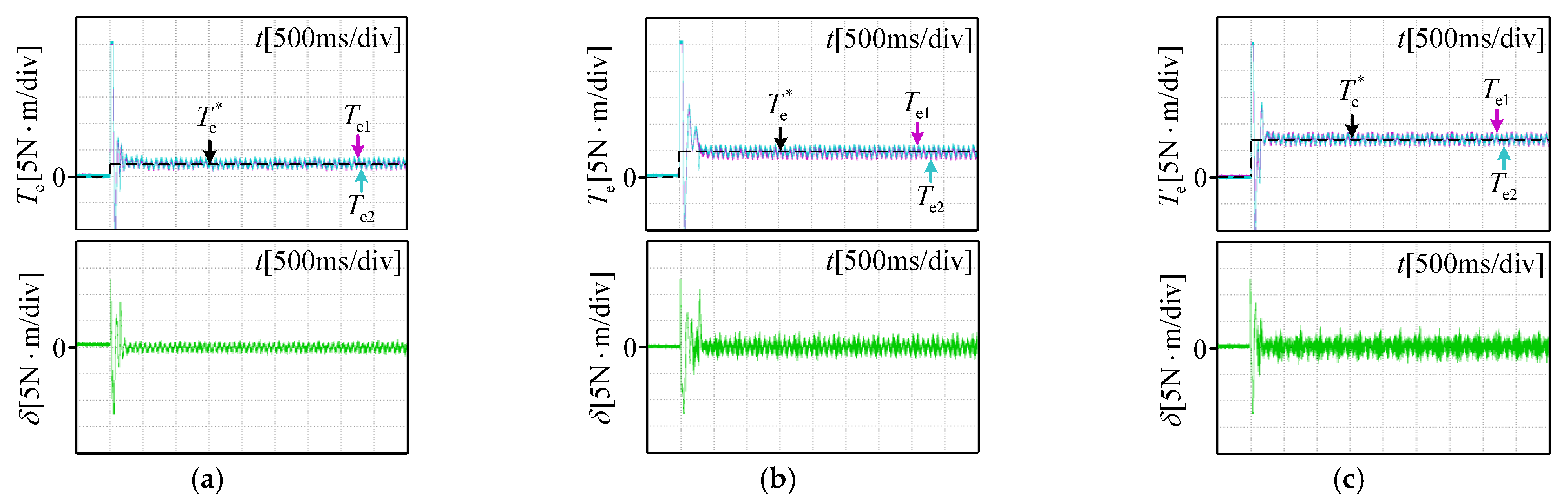
5.2. Steady State Performance Comparison Experiments

The steady-state performance of the two control strategies is compared and analyzed through experiments. The reference speed is set to 200 r/min, and the total load torque is 5 N·m, 10 N·m and 15 N·m, respectively. Under the closed-loop control strategy based on the master-slave structure, the experimental waveforms of torque and the torque synchronization error of the dual-motor are shown in Figure 13.
It can be seen from Figure 13 that under three different load torques, the output torque of a single motor is 2.5 N·m, 5 N·m, and 7.5 N·m, respectively, the transient torque synchronization errors during the starting process are very large, and the steady-state torque synchronization errors are controlled within ±1.8 N·m, ±2.1 N·m, and ±2.5 N·m, respectively. Although the closed-loop control strategy based on the master-slave structure can ensure the motor has good torque tracking performance, the torque synchronization error increases significantly with the increase in load torque. Therefore, the closed-loop control strategy based on the master-slave structure cannot effectively restrain the increasing trend of the torque synchronization error.
The auxiliary diagonal matrix Mopt obtained by simulation is applied, and the experimental waveforms of the torque and the torque synchronization error under the proposed FCS-MPC strategy based on standard quadratic cost function are shown in Figure 14.
It can be seen from Figure 14 that after applying the proposed FCS-MPC strategy based on standard quadratic cost function, under different total load torques, the torque synchronization error is obviously reduced. The torque synchronization error is kept in the range of ±5 N·m during the starting process, and the steady-state torque synchronization error is within ±1.5 N·m. The trend of the torque synchronization error increasing with the increase in load torque is further restrained. The output torque of a single motor is half of the total load torque, and the system has good torque tracking performance. The experimental results show that the proposed FCS-MPC strategy can effectively improve the torque synchronization performance of the dual-motor while ensuring good torque tracking performance for a single motor.

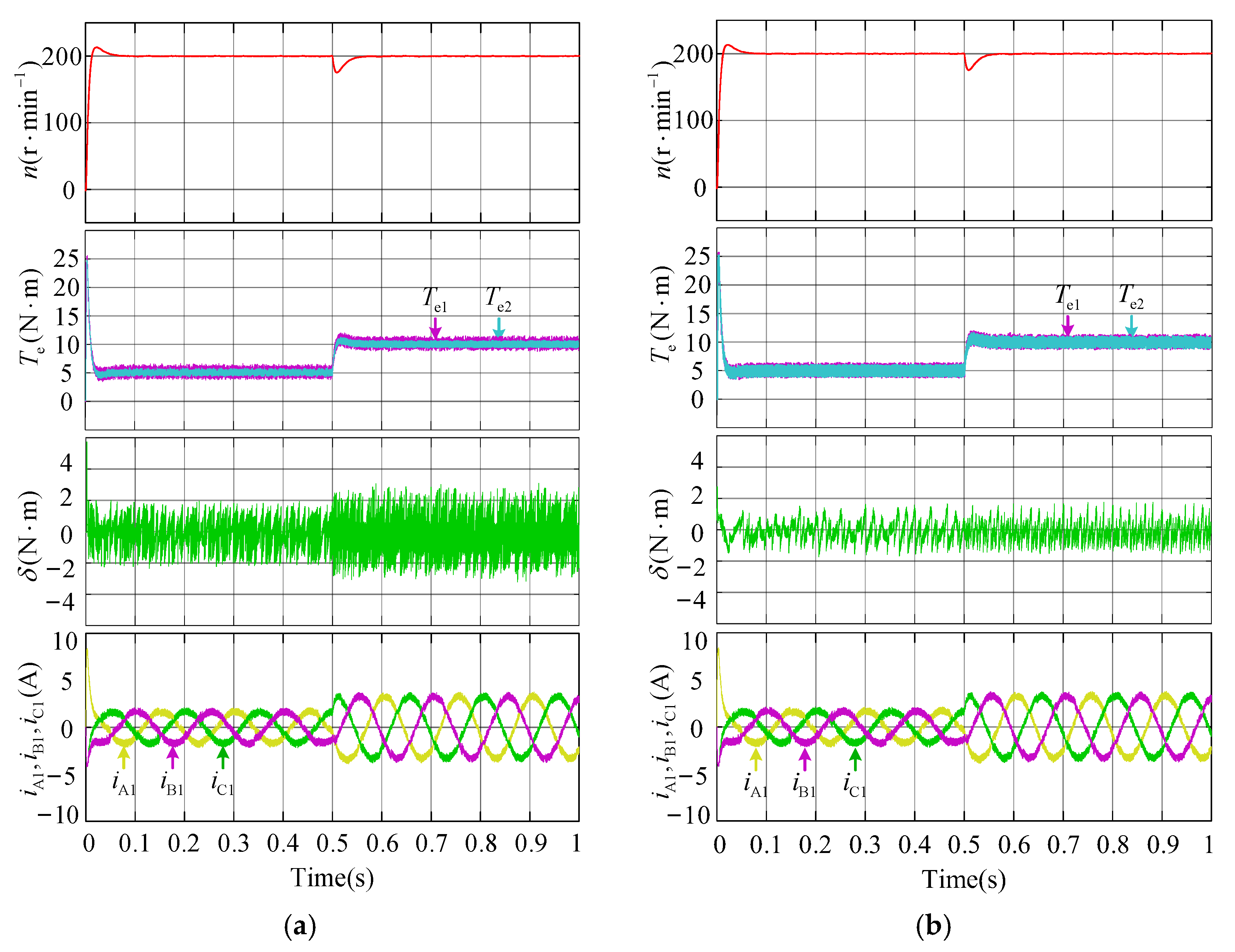
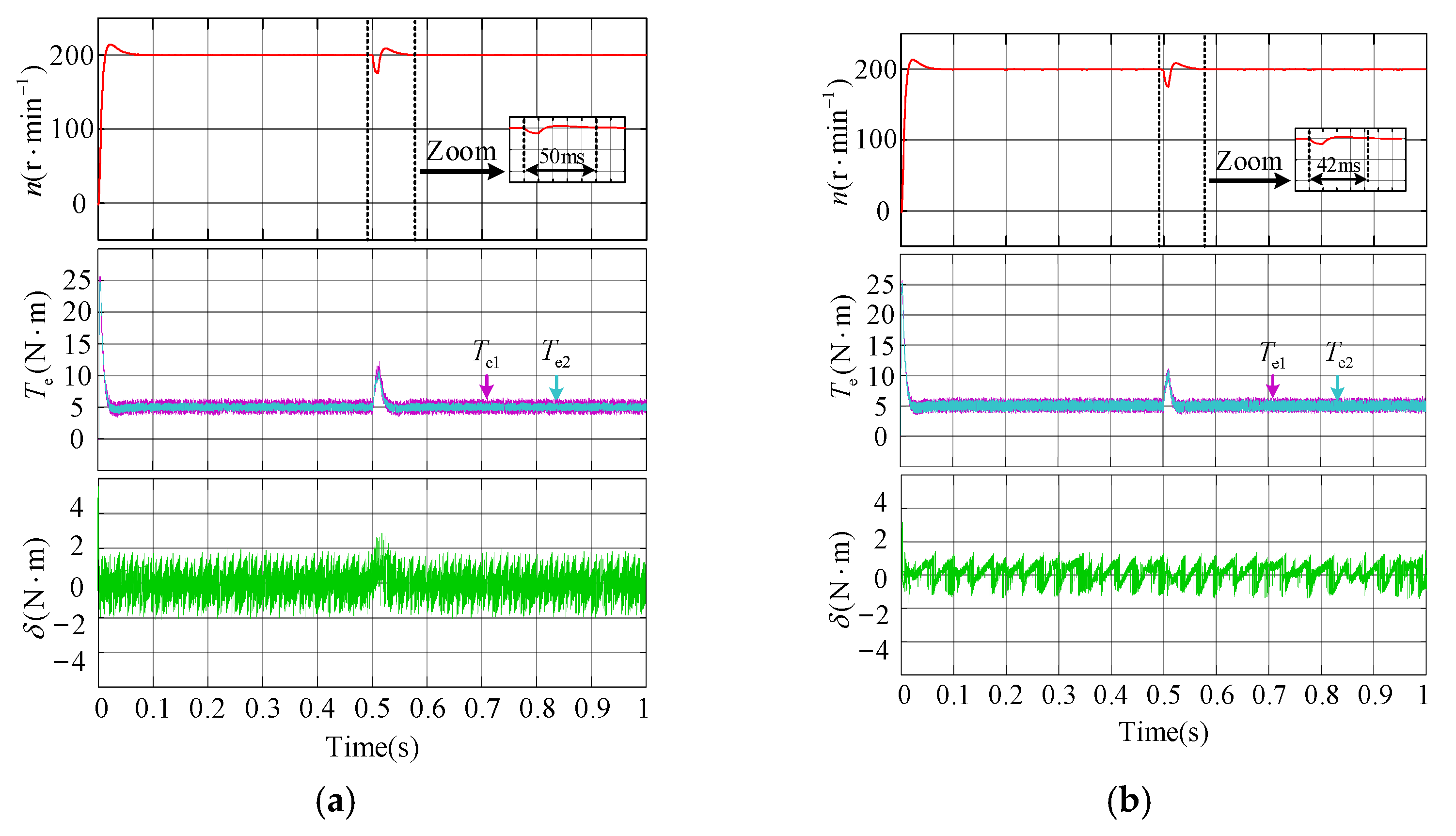
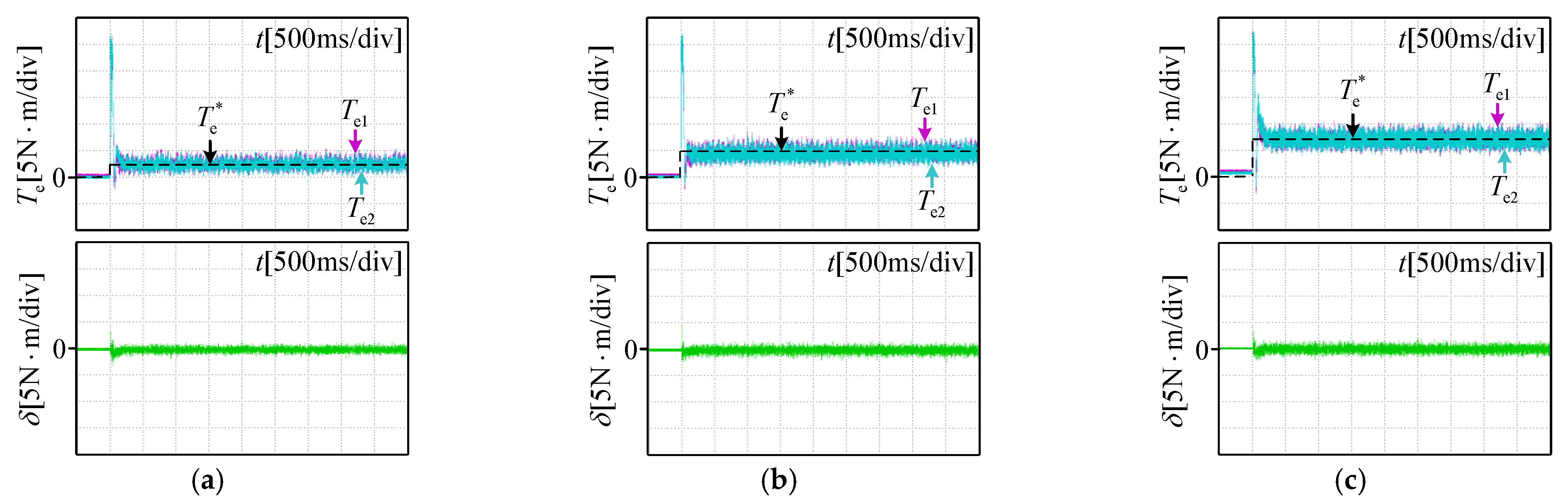
5.3. Dynamic Performance Comparison Experiments

To compare the control effect of the two control strategies in the process of motor dynamic operation, the following experiments are designed: the reference speed is set as 200 r/min, the initial load torque is 5 N·m, and the load torque is stepped to 15 N·m at 2.5 s. Under the condition of step load torque, the waveforms of the speed, the torque, the torque synchronization error term and the stator current when using the closed-loop control strategy and the proposed FCS-MPC strategy are shown in Figure 15.
It can be seen from Figure 15a that the output torque of a single motor before the load step of the conventional closed-loop control strategy is 2.5 N·m, and the output torque of a single motor after the load step is 7.5 N·m. The torque synchronization error before and after the load torque step process is within ±1.8 N·m and ±2.3 N·m, and the torque synchronization error fluctuates significantly during the load torque step process. In addition, the response time of the closed-loop control strategy to the load torque step is about 39 ms.
The proposed FCS-MPC strategy obtains the experimental results of the load torque step as shown in Figure 15b. In the figure, the output torque of a single motor before and after the load torque step is half of the load torque. The torque synchronization error of the dual-motor in the steady state process and the load torque step process is within ±1.5 N·m, and the torque synchronization error does not fluctuate significantly during the sudden load change. Compared with the closed-loop control strategy, the torque and synchronization error are reduced by 17% and 35%, respectively, before and after the load change. At the same time, compared with Figure 15a, there is no significant fluctuation in the current waveforms before and after the load torque step. In addition, the response time of the proposed FCS-MPC strategy to the load torque step is 5 ms shorter than the closed-loop control strategy, which shows that the proposed FCS-MPC strategy not only improves the torque synchronization torque performance of the system, but also improves the dynamic response ability of the system.
In conclusion, the proposed FCS-MPC strategy realizes the closed-loop control of the torque synchronization error due to the coupling relationship established in the inner loop control of a single motor, and the weight coefficient matrix obtained by offline solution can ensure the convergence of each error term. Therefore, the proposed FCS-MPC strategy can not only consider the torque synchronization performance and tracking performance of the system, but also further improve the anti-interference performance of the system.

6. Conclusions

In the FCS-MPC of a dual-motor torque synchronous system fed by an IMC, the cost function is the key to system optimization, in which the weight coefficients regulate the effect of each variable. The form of cost function and the selection of the weight coefficients directly affect the performance of the FCS-MPC strategy. Therefore, this paper proposed an FCS-MPC strategy based on the standard quadratic cost function. By establishing the unified prediction model of the dual-motor and constructing the auxiliary diagonal matrix, the cost function was designed as the standard quadratic form, and the offline solution algorithm based on the Lyapunov stability theory was used to select the weight coefficients. The proposed FCS-MPC strategy can ensure that the cost function is the Lyapunov function in the continuous control period, and then ensure that the error vector converges to zero and the system is asymptotically stable. It not only solves the problem of weight coefficients self-tuning, but it can also be extended to a multi-motor torque synchronization system, which has a broader development prospect.

Author Contributions

Z.W., S.L. and T.S. put forward the idea and designed the experiments; S.L. performed the experiments and analyzed the results; S.L., Y.Y. and T.S. reviewed and edited the manuscript; all authors contributed to the writing of the paper. All authors have read and agreed to the published version of the manuscript.

Funding

This research was funded by [Major Program of the National Natural Science Foundation of China] grant number [51690183] and [National Natural Science Foundation of China] grant number [51777135].

Institutional Review Board Statement

Not applicable.

Informed Consent Statement

Not applicable.

Data Availability Statement

Data available on request due to restrictions e.g., privacy or ethical. The data presented in this study are available on request from the corresponding author. The data are not publicly available due to the need for further research.

Conflicts of Interest

The authors declare no conflict of interest.

References

  1. Lopez, M.; Rodriguez, J.; Silva, C.; Rivera, M. Predictive Torque Control of a Multidrive System Fed by a Dual Indirect Matrix Converter. IEEE Trans. Ind. Electron. 2015, 62, 2731–2741. [Google Scholar] [CrossRef]
  2. Bak, Y.; Lee, E.; Lee, K.-B. Indirect Matrix Converter for Hybrid Electric Vehicle Application with Three-Phase and Single-Phase Outputs. Energies 2015, 8, 3849–3866. [Google Scholar] [CrossRef]
  3. Kumar, D.; Wheeler, P.W.; Clare, J.C.; Kim, T.-W. Weight/volume effective multi-drive system based on two-stage matrix converter. In Proceedings of the Industrial Electronics Conference, Orlando, FL, USA, 10–13 November 2008; pp. 2782–2787. [Google Scholar]
  4. Kumar, D.; Wheeler, P.; Clare, J.; De Lillo, L. Experimental evolution of the multi-drive system based on two-stage direct power converter topology. In Proceedings of the 14th International Power Electronics and Motion Control Conference, Ohrid, North Macedonia, 6–8 September 2010; pp. T5204–T5212. [Google Scholar]
  5. Lucia, O.; Carretero, C.; Burdio, J.M.; Acero, J.; Almazan, F. Multiple-output resonant matrix converter for multiple induction heaters. IEEE Trans. Ind. Appl. 2012, 48, 1387–1396. [Google Scholar] [CrossRef]
  6. Chen, W.; Liu, X.; Shi, T.N.; Xia, C.L. Generalized predictive cross-coupling position control of biaxial motion system. Control Theory Appl. 2018, 35, 399–406. [Google Scholar]
  7. Chen, Z.; He, J.; Zheng, Y.; Song, T.; Deng, Z. An optimized feedforward decoupling PD register control method of roll-to-roll web printing systems. IEEE Trans. Autom. Control. 2016, 13, 274–283. [Google Scholar] [CrossRef]
  8. Jin, Y.S.; Xu, Y.X.; Wang, Q.; Hu, J.H. Research on torque balance control of multi-motor based on master-slave control structure. Micromotors 2016, 49, 58–61. [Google Scholar]
  9. Deng, Z.; Nian, X. Robust control of two parallel-connected permanent magnet synchronous motors fed by a single inverter. IET Power Electron. 2016, 9, 2833–2845. [Google Scholar] [CrossRef]
  10. Kumar, D.; Wheeler, P.W.; Clare, J.C. A multi-drive system based on direct power converter. In Proceedings of the 13th European Conference on Power Electronics and Applications, Barcelona, Spain, 8–10 September 2009. [Google Scholar]
  11. Mei, Y.; Chang, N.Q.; Li, Z.X. Research on high performance speed regulating system of multi-machine drive based on indirect matrix converter. Micromotors 2012, 45, 56–60. [Google Scholar]
  12. Ahmed, A.A.; Koh, B.K.; Park, H.S.; Lee, K.-B.; Lee, Y.I. Finite-Control Set Model Predictive Control Method for Torque Control of Induction Motors Using a State Tracking Cost Index. IEEE Trans. Ind. Electron. 2017, 64, 1916–1928. [Google Scholar] [CrossRef]
  13. Shi, T.N.; Zhang, B.J.; Liu, T.; Wei, Y.C.; Xia, C.L. The optimal modulation strategy of dual permanent magnet synchronous motor driven by five-bridge arm inverter. Proc. Chin. Soc. Electr. Eng. 2015, 35, 1498–1507. [Google Scholar]
  14. Siami, M.; Khaburi, D.A.; Rodriguez, J. Simplified finite control set-model predictive control for matrix converters-fed PMSM drives. IEEE Trans. Ind. Electron. 2018, 33, 2438–2446. [Google Scholar] [CrossRef]
  15. Xiao, X.; Wang, J.X.; Zhang, Y.J.; Hao, C. An optimized master-slave model predictive direct torque control scheme for the dual motor. Trans. China Electrotech. Soc. 2018, 33, 5720–5730. [Google Scholar]
  16. Davari, S.A.; Khaburi, D.A.; Kennel, R. Using a weighting factor table for FCS-MPC of induction motors with extended prediction horizon. In Proceedings of the 38th Annual Conference on IEEE Industrial Electronics Society, Montreal, QC, Canada, 25–28 October 2012; pp. 2086–2091. [Google Scholar]
  17. Gu, X.; Jiang, B.; Geng, Q.; Liu, T. Model predictive control of dual permanent magnet synchronous motor bridge arm converter. Adv. Technol. Electr. Eng. Energy 2015, 34, 25–30. [Google Scholar]
  18. Wróbel, K.; Serkies, P.; Szabat, K. Model Predictive Base Direct Speed Control of Induction Motor Drive—Continuous and Finite Set Approaches. Energies 2020, 13, 1193. [Google Scholar] [CrossRef] [Green Version]
  19. Lim, C.; Levi, E.; Jones, M.; Rahim, N.A.; Hew, W.P. A comparative study of synchronous current control schemes based on FCS-MPC and PI-PWM for a two-motor three-phase drive. IEEE Trans. Ind. Electron. 2014, 61, 3867–3878. [Google Scholar] [CrossRef] [Green Version]
  20. Davari, S.A.; Khaburi, D.A.; Kennel, R. An improved FCS–MPC algorithm for an induction motor with an imposed optimized weighting factor. IEEE Trans. Ind. Electron. 2012, 27, 1540–1551. [Google Scholar] [CrossRef]
  21. Shi, T.N.; Yang, Y.Y.; Zhou, Z.Q.; Geng, Q.; Xia, C.L. FCS-MPC for dual-motor torque synchronization system based on quadratic form cost function. Proc. Chin. Soc. Electr. Eng. 2019, 39, 4531–4541. [Google Scholar]
Figure 1. Topology of the dual-motor system fed by an indirect matrix converter (IMC).
Energies 14 01325 g001
Figure 2. Control structure diagram of the dual-motor system fed by an IMC.
Energies 14 01325 g002
Figure 3. Input voltage sector division.
Energies 14 01325 g003
Figure 4. Inverter controller based on master-slave structure.
Energies 14 01325 g004
Figure 5. Inverter controller based on a finite set model predictive control (FCS-MPC) structure.
Energies 14 01325 g005
Figure 6. Simulation results of the different loads: (a) load torque is 10 N·m and (b) load torque is 20 N·m.
Energies 14 01325 g006
Figure 7. Simulation results for step change of load torque: (a) the closed-loop control strategy and (b) the proposed FCS-MPC strategy.
Energies 14 01325 g007
Figure 8. Simulation results for load torque disturbance: (a) the closed-loop control strategy and (b) the proposed FCS-MPC strategy.
Energies 14 01325 g008
Figure 9. Simulation results with Rs2/Rs1 = 1.3, L2/L1 = 1.3: (a) the closed-loop control strategy and (b) the proposed FCS-MPC strategy.
Energies 14 01325 g009
Figure 10. Simulation results for load torque disturbance with Rs2/Rs1 = 1.3, L2/L1 = 1.3: (a) the closed-loop control strategy and (b) the proposed FCS-MPC strategy.
Energies 14 01325 g010
Figure 11. Steady states of synchronous torque control strategies with different inductance and resistance.
Energies 14 01325 g011
Figure 12. The experiment platform.
Energies 14 01325 g012
Figure 13. Steady-state waveforms of closed-loop control strategy based on master-slave structure: (a) load torque is 5 N·m, (b) load torque is 10 N·m and (c) load torque is 15 N·m.
Energies 14 01325 g013
Figure 14. Steady-state waveforms of the proposed FCS-MPC strategy: (a) load torque is 5 N·m, (b) load torque is 10 N·m and (c) load torque is 15 N·m.
Energies 14 01325 g014
Figure 15. Waveforms for step change of load torque: (a) the closed-loop control strategy and (b) the proposed FCS-MPC strategy.
Energies 14 01325 g015
Table 1. Switch state on rectifier in each interval.
SectorSmnDuty RatioSmnDuty Ratio
1Sau Sblub/uaSau Scluc/ua
2Sbu Sclub/ucSau Sclua/uc
3Sbu Scluc/ubSbu Salua/ub
4Scu Saluc/uaSbu Salub/ua
5Scu Salua/ucScu Sblub/uc
6Sau Sblua/ubScu Sbluc/ub
Table 2. Parameters of the SPMSM.
VariablesDescriptionValues
PNRated power4 kW
JInertia0.0065 kg·m2
nNRated speed1500 r/min
LInductance19.85 mH
RResistance0.929 Ω
ψfFlux linkage1.0267 Wb
pPole2
Publisher’s Note: MDPI stays neutral with regard to jurisdictional claims in published maps and institutional affiliations.

