Article

Discrete Terminal Super-Twisting Current Control of a Six-Phase Induction Motor

1
Power Electronics and Industrial Control Research Group (GRÉPCI), École de Technologie Supérieure, Montreal, QC H3C 1K3, Canada
2
Applied Power Electronics Technology Research Group (APET), Universidad de Vigo, Lagoas Marcosende, 36310 Vigo, Spain
3
Laboratory of Power and Control Systems (LSPyC), Facultad de Ingeniería, Universidad Nacional de Asunción, Luque 2060, Paraguay
*
Author to whom correspondence should be addressed.
Energies 2021, 14(5), 1339; https://doi.org/10.3390/en14051339
Submission received: 29 December 2020 / Revised: 18 February 2021 / Accepted: 25 February 2021 / Published: 1 March 2021
(This article belongs to the Special Issue Control of Power Electronics Converters and Electric Motor Drives)

Abstract

:
In this manuscript, the high-accuracy stator currents tracking issue is considered for a six-phase induction motor subject to external perturbations and uncertainties due to unmeasurable rotor currents and electrical parameter variations. To achieve the control goals, the common two-cascade controllers structure is required for this type of motor. The first controller in the outer loop consists of a proportional integral to regulate the speed. Then, the second is the proposed inner nonlinear stator currents controller based on a robust discrete-time terminal super-twisting algorithm supported by the time-delay estimation method. For the design procedure, the discrete-time stator currents dynamics are derived; for example, the vector of the matched perturbations and unmeasurable rotor currents are specified to simplify the estimation. A detailed stability analysis of the closed-loop error dynamics using Lyapunov theory is given. Finally, a real asymmetrical six-phase induction motor is used to implement in real-time the developed method and to illustrate its effectiveness and robustness. The results obtained reveal a satisfactory stator currents tracking in steady state and transient conditions and under variation in the magnetizing inductance. Moreover, a comparative study with an existing method in steady state for two different rotor speeds is presented to show the superiority of the proposed discrete-time technique.

1. Introduction

Nowadays, multiphase motor drives are extensively utilized in several real-life systems such as wind turbines [1], electric vehicles [2], ship propulsion system [3], and traction system for elevators [4] and others that have aroused a significant interest among the community of automation engineers and researchers to develop advanced nonlinear control techniques ensuring high-accurate stator currents tracking [5,6]. This interest belongs to the fact that these motors produce lower current/power per phase and lower torque ripple in comparison with well-known three-phase motors. In addition, multiphase motors are able to operate in faulty situations without the requirement of additional hardware [7]. However, the presence of uncertain parameters, unmeasured rotor currents, and matched perturbations make the control task complicated.
In the literature, earlier works considered similar methods applied to three-phase motors and proposed the extended version of the Proportional-Integral (PI) regulator [8], direct torque control [9], model predictive control [10,11], and others. Recently, advanced digital platforms encouraged the researchers to apply advanced intelligent and nonlinear control techniques such as fuzzy logic [12,13], nonlinear backstepping [14,15], Sliding Mode (SM) control [16,17,18], and others.
Among the abovementioned methods, SM control is simply designed and is considered the most effective due to its good features that can be resumed by the following points [19]:
  • insensitivity to a wide class of matched uncertainties and disturbances, and
  • finite-time convergence of the commanded system trajectories to the selected sliding functions.
SM ensures these two features by using discontinuous input signals. However, this discontinuity limits SM’s real-time implementation since it generates high-frequency switching signals that are the famous chattering phenomenon [20]. Therefore, this undesirable phenomenon can easily have irreversible damages on controlled-system actuators. Therefore, to reduce the extent of the chattering problem, discretized versions of the SM based on reaching law have been proposed [21,22,23]. Through several numerical simulations and experimental work, it has been concluded that the SM phase is no longer maintained even if the finite-time convergence to the sliding function is maintained, which introduced Discrete-time Quasi SM (DQSM) control [24]. In this method, the system trajectories converge to a band in the vicinity of the designed sliding function, where the bandwidth depends on the used reaching law.
To enhance the DQSM performance and to reduce the Quasi Sliding Mode Band (QSMB), a combination of the Time-Delay Estimation (TDE) method with DQSM based on exponential reaching law has been proposed for an asymmetrical six-phase Induction Motor (IM) [18]. This method aims to reproduce approximated signals to unmeasurable rotor currents and matched uncertainties and perturbations based on time-delayed computed voltages and measured states to minimize the choice of switching gains. However, a dilemma arose: small switching gains reduce chattering but deteriorate the tracking performance while large switching gains increase simultaneously the chattering level and the tracking accuracy but degrade the quality of electric energy (i.e., total harmonic distortion becomes high). This dilemma has been revealed through experimental works on a real six-phase IM using Gao’s reaching law and exponential reaching law [17,18].
As a solution, a TDE-based discrete-time super-twisting controller has been developed and implemented on the same asymmetrical six-phase IM [25]. The proposed method allows for higher precision while reducing chattering and improves electric energy quality. In this work, an attempt is made to enhance the results obtained using the abovementioned discrete-time second-order SM technique. The contributions of this work are summarized as follows:
  • A terminal sliding function that is a nonlinear one instead of the conventional linear sliding function in [17] is introduced. Consequently, a faster convergence is obtained during the reaching phase.
  • The matched external perturbations, unmodeled dynamics due to the unmeasurable rotor currents, and electrical parameters’ variations are approximated using the TDE method. This latter is simple and easy to implement since it requires delayed determinate voltages, and actual and delayed existing measured stator currents.
  • The estimated perturbations and dynamics are combined with the developed control law based on the discrete form of the super-twisting that is a second-order SM algorithm. Besides the good properties of this algorithm, the proposed combination ensures stability while choosing small super-twisting gains without a priori knowledge of the upper bound of the uncertainties. In addition, to the author’s best knowledge, few works considered this algorithm in the control part.
  • The proposed Discrete-time Terminal Super-Twisting Control (DTSTC) combined with the TDE are implemented in real-time on a real asymmetrical six-phase IM to support the theoretical developments, to improve the performance, and to demonstrate that it is appropriate for multiphase IM stator current control. The proposed discrete-time technique can be extended easily to any n-phase induction motor and generator.
The rest of the manuscript is organized as follows. The continuous-time studied asymmetrical six-phase IM model and its discretization and the Voltage Source Converter (VSC) are detailed in Section 2. The developed discrete-time nonlinear technique is designed and the stability of the closed-loop system is analyzed in Section 3. In Section 4, the experimental results of four scenarios in transient and steady-state conditions are presented. Finally, Section 5 draws some conclusions.

2. Preliminaries

Consider the mathematical model of the asymmetrical six-phase IM powered by six-leg VSC [17,18] represented in Figure 1:
d d t i α r ( t ) = C 2 R r i α r ( t ) C 2 L r ω r ( t ) i β r ( t ) + C 1 R s i α s ( t ) C 2 L m ω r ( t ) i β s ( t ) C 1 v α s ( t ) d d t i β r ( t ) = C 2 L r ω r ( t ) i α r ( t ) C 2 R r i β r ( t ) + C 2 L m ω r ( t ) i α s ( t ) + C 1 R s i β s ( t ) C 1 v β s ( t ) d d t i α s ( t ) = C 1 R r i α r ( t ) + C 1 L r ω r ( t ) i β r ( t ) C 3 R s i α s ( t ) + C 1 L m ω r ( t ) i β s ( t ) + C 3 v α s ( t ) d d t i β s ( t ) = C 1 L r ω r ( t ) i α r ( t ) + C 1 R r i β r ( t ) C 1 L m ω r ( t ) i α s ( t ) C 3 R s i β s ( t ) + C 3 v β s ( t ) d d t i x s ( t ) = C 4 R s i x s ( t ) + C 4 v x s ( t ) d d t i y s ( t ) = C 4 R s i y s ( t ) + C 4 v y s ( t )
where v α s ( t ) , v β s ( t ) , v x s ( t ) , and v y s ( t ) are the stator input voltages; { i α r ( t ) , i β r ( t ) } and { i α s ( t ) , i β s ( t ) } are the unmeasurable rotor currents and the stator currents in the flux/torque producing α β subspace, respectively; i x s ( t ) and i y s ( t ) are the stator currents in the loss-producing x y subspace; the coefficients C 1 to C 4 are given by C 1 = L m L r L s L m 2 , C 2 = L s L m C 1 , C 3 = L r L m C 1 , and C 4 = 1 L l s , with
R s
as the resistance of the stator,
R r
as the resistance of the rotor,
L m
as the magnetizing inductance,
L s
as the inductance of the stator,
L l s
as the leakage inductance of the stator, and
L r
as the inductance of the rotor;
and finally ω r ( t ) denotes the rotor electrical speed that is described by
ω ˙ r ( t ) = B M J M ω r ( t ) + P p J M T e ( t ) T L ( t )
where T e ( t ) = 3 P p ψ α s ( t ) i β s ( t ) ψ β s ( t ) i α s ( t ) is the generated torque with P p ass the number of pole pairs and ψ α s ( t ) and ψ β s ( t ) as the stator fluxes, T L ( t ) is the load torque, and B M and J M are the coefficients of the friction and the inertia, respectively.
The considered system in Equation (1) is obtained using the vector space decomposition method that consists of the following transformation matrix:
T 6 = 1 3 1 3 2 1 2 3 2 1 2 0 0 1 2 3 2 1 2 3 2 1 1 3 2 1 2 3 2 1 2 0 0 1 2 3 2 1 2 3 2 1 1 0 1 0 1 0 0 1 0 1 0 1 .
Based on the Euler approximation method, the discrete-time model of the measured stator currents of the studied motor is obtained as follows:
X ( k + 1 ) = F ( k ) + G v ( k ) + H ( k )
where ( k ) = ( k T s ) , with T s as a sufficiently small sampling period, and the α β and x y stator currents represent the state vector:
X ( k ) = i α s ( k ) , i β s ( k ) , i x s ( k ) , i y s ( k ) T
while the known dynamics F ( k ) and G and the unknown dynamics H ( k ) are defined by
F ( k ) = ( 1 T s C 3 R s ) i α s ( k ) + T s C 1 L m ω r ( k ) i β s ( k ) T s C 1 L m ω r ( k ) i α s ( k ) + ( 1 T s C 3 R s ) i β s ( k ) ( 1 T s C 4 R s ) i x s ( k ) ( 1 T s C 4 R s ) i x y ( k ) ,
G = T s C 3 0 0 0 0 T s C 3 0 0 0 0 T s C 4 0 0 0 0 T s C 4 ,
H ( k ) = T s C 1 R r i α r ( k ) + T s C 1 L r ω r ( k ) i β r ( k ) + n α s ( k ) T s C 1 L r ω r ( k ) i α r ( k ) + T s C 1 R r i β r ( k ) + n β s ( k ) n x s ( k ) n y s ( k ) ,
with n s ( k ) as the matched disturbance acting on the i s ( k ) stator current. Notice that H i ( k ) = O ( T s ) is bounded | H i ( k ) | T s ϱ i < and is of the order one with respect to the sampling time. Finally, the input vector is defined by
v ( k ) = v α s ( k ) , v β s ( k ) , v x s ( k ) , v y s ( k ) T .
Due to the following VSC model, we have
M = 1 3 2 0 1 0 1 0 0 2 0 1 0 1 1 0 2 0 1 0 0 1 0 2 0 1 1 0 1 0 2 0 0 1 0 1 0 2 S a S b S c S d S e S f ,
where S j for j = a , b , c , d , e , f is the gating signals that can switch between 0 and 1. Finally, the above VSC model and the input vector (9) are linked by
V dc T M = v ( k ) ,
where V dc denotes the dc bus voltage.

3. Enhanced DTSTC

3.1. Outer Speed Control Loop

In this outer control loop, the mechanical speed is regulated using the following PI [26]:
i q s d = K I ( ω d ω ) s + K P ( ω d ω ) .
It can be noticed from the above equation that the PI regulator generates the desired dynamic current i q s d and then, as shown in the structure of closed-loop system (see Figure 2), the desired α β stator currents are computed.

3.2. Inner Current Control Loop

In this part, the inner loop aims to ensure accurate α β and x y stator currents tracking by designing a DTSTC law even if the α β rotor currents are not measurable and in the presence if the matched perturbations. In one hand, the discrete terminal sliding function is defined by:
S ( k ) = E ( k ) + Λ 1 E ( k 1 ) + Λ 2 Sig γ ( E ( k 1 ) ) .
where E ( k ) = X ( k ) X d ( k ) is the current tracking error with X d ( k ) = [ i α s d ( k ) , i β s d ( k ) , i x s d ( k ) , i y s d ( k ) ] T as the desired stator current vector; Λ 1 and Λ 2 are two ( 4 × 4 ) positive definite diagonal matrices; and Sig γ ( E ( k 1 ) ) = [ | E 1 ( k 1 ) | γ 1 sign ( E 1 ( k 1 ) ) , , | E 4 ( k 1 ) | γ 4 sign ( E 4 ( k 1 ) ) ] T , with γ i ( 0 , 1 ) for i = 1 , , 4 such that
Sig 0 ( E i ( k ) ) = 0 , if E i ( k ) = 0 1 , if E i ( k ) < 0 1 , if E i ( k ) > 0
Then, S ( k + 1 ) is computed as follows:
S ( k + 1 ) = E ( k + 1 ) + Λ 1 E ( k ) + Λ 2 Sig γ ( E ( k ) ) = X ( k + 1 ) X d ( k + 1 ) + Λ 1 E ( k ) + Λ 2 Sig γ ( E ( k ) ) = F ( k ) + G v ( k ) + H ^ ( k ) X d ( k + 1 ) + Λ 1 E ( k ) + Λ 2 Sig γ ( E ( k ) ) ,
where H ^ ( k ) is the estimate vector of H ( k ) obtained using the TDE method defined as in [27]:
H ^ ( k ) H ( k 1 ) = X ( k ) F ( k 1 ) + G v ( k 1 ) .
As said before, the above estimation is accurate if and only if the variations in the functions of the vector H ( k ) are small during two consecutive sampling times. Moreover, adding this estimation to the control law ensures better performances and allows for the choice of smaller control gains that result in low control efforts.
On the other hand, the discrete super-twisting algorithm is defined by the following:
S ( k + 1 ) = Q 1 S ( k ) T s Q 2 Sig 0.5 ( S ( k ) ) + T s R ( k ) R ( k + 1 ) = Q 3 R ( k ) T s Q 4 Sig 0 ( S ( k ) )
where Q 1 = diag ( Q 11 , , Q 14 ) , Q 2 = diag ( Q 21 , , Q 24 ) , Q 3 = diag ( Q 31 , , Q 34 ) , and Q 4 = diag ( Q 41 , , Q 44 ) are diagonal positive matrices, where the elements of Q 1 and Q 3 are ( 0 , 1 ) while the elements of Q 2 and Q 4 are fixed in the proof.
Hence, combining Equations (15) and (17) yields the following:
v ( k ) = G 1 F ( k ) + H ^ ( k ) X d ( k + 1 ) Q 1 S ( k ) + T s Q 2 Sig 0.5 ( S ( k ) ) T s R ( k ) R ( k + 1 ) = Q 3 R ( k ) T s Q 4 Sig 0 ( S ( k ) ) .
Theorem 1.
Consider the discrete-time model of the measured stator currents of the six-phase IM system (5) if the conditions below are met for i = 1 , , 4 :
Q 2 i > 0 ,
Q 4 i > ( 1 + Q 3 i ) T s δ h i .
Then, the developed DTSTC law computed in Equation (18) guarantees convergence of each stator current tracking error to a ball in the vicinity of the equilibrium point such that the maximal value of his radius is given by
r m a x = 0.25 σ 2 + σ 3 2 L ¯ 1 2 + σ 1 + σ 2 δ .
Proof of Theorem 1.
Substituting the computed DTSTC (18) into the measured stator currents dynamics (5) gives
S ( k + 1 ) = Q 1 S ( k ) T s Q 2 Sig 0.5 ( S ( k ) ) + T s R ( k ) + Δ H ( k ) R ( k + 1 ) = Q 3 R ( k ) T s Q 4 Sig 0 ( S ( k ) )
where H ˜ ( k ) = H ( k ) H ( k 1 ) = O ( T s 2 ) is the estimation error that is bounded such that, for i = 1 , , 4 ,
| H ˜ i ( k ) | T s δ h i
where T s δ h i is a positive constant smaller than T s ϱ i that is the upper bound of H i ( k ) .
For each stator current ( i = 1 , , 4 ), the closed-loop error dynamics can be expressed as a subsystem:
S i ( k + 1 ) = Q 1 i S i ( k ) T s Q 2 i | S i ( k ) | 0.5 sign ( S i ( k ) ) + H ˜ i ( k ) + T s R i ( k ) R i ( k + 1 ) = Q 3 i R i ( k ) T s Q 4 i sign ( S i ( k ) )
To simplify the proof, a new variable is introduced W i ( k ) = R i ( k ) + T s 1 H ˜ i ( k ) ; then, the above equation can be rewritten in a matrix form as follows:
S i ( k + 1 ) W i ( k + 1 ) Y i ( k + 1 ) = Q 1 i T s 0 Q 3 i A S i ( k ) W i ( k ) Y i ( k ) + T s Q 2 i | S i ( k ) | 0.5 T s Q 4 i + Z i ( k ) sign ( S i ( k ) ) B ( k ) sign ( S i ( k ) )
Z i ( k ) = T s 1 H ˜ i ( k + 1 ) Q 3 i H ˜ i ( k )
such that Z i ( k ) is bounded as follows:
Z i ( k ) = T s 1 H ˜ i ( k + 1 ) Q 3 i H ˜ i ( k ) T s 1 | H ˜ i ( k + 1 ) Q 3 i H ˜ i ( k ) | T s 1 | H ˜ i ( k + 1 ) | + Q 3 i | H ˜ i ( k ) | T s 1 T s δ h i + Q 3 i T s δ h i δ h i ( 1 + Q 3 i )
Once the discrete closed-loop error dynamics for each stator current is formulated, the following discrete Lyapunov function is selected:
V ( k ) = Y i T ( k ) P Y i ( k )
where P = P T R 2 × 2 is a symmetric definite positive matrix. Notice that the same P matrix can be chosen for all currents stability analyses. Then,
Δ V ( k ) = V ( k + 1 ) V ( k ) = Y i T ( k + 1 ) P Y i ( k + 1 ) Y i T ( k ) P Y i ( k )
Substituting Equation (25) into (28) yields
Δ V ( k ) = Y i T ( k ) ( A T P A P ) Y i ( k ) + B T ( k ) P B ( k ) + 2 Y i T ( k ) A T P B ( k ) sign ( S i ( k ) ) .
Using the following Γ -matrix inequality [28]
A T B + B T A A T Γ A + B T Γ 1 B ,
Equation (25) becomes
Δ V ( k ) Y i T ( k ) ( A T P A P ) Y i ( k ) + B T ( k ) P B ( k ) + Y i T ( k ) ( A T P Γ P A ) Y i ( k ) + B T ( k ) Γ 1 B ( k ) Y i T ( k ) ( A T ( P + P Γ P ) A ( 1 δ ) P ) Y i ( k ) + B T ( k ) ( P + Γ 1 ) B ( k ) δ V ( k ) Y i T ( k ) L Y i ( k ) + B T ( k ) ( P + Γ 1 ) B ( k ) δ V ( k )
where δ ( 0 , 1 ) and L R 2 × 2 is a symmetric definite positive matrix that solves the following:
L = A T ( P + P Γ P ) A ( δ 1 ) P .
Moreover, taking into account the conditions in (19), the term B T ( k ) ( P + Γ 1 ) B ( k ) can be expanded as follows:
B T ( k ) ( P + Γ 1 ) M B ( k ) = σ 1 + σ 2 | S i ( k ) | 0.5 + σ 3 | S i ( k ) | σ 1 + σ 2 ( 1 + | S i ( k ) | ) + σ 3 | S i ( k ) | σ 1 + σ 2 + ( σ 2 + σ 3 ) | S i ( k ) |
where
σ 1 = M 22 Z i ( k ) s i g n ( S i ( k ) ) T s Q 4 i 2 σ 2 = 2 T s Q 2 i M 21 [ Z i ( k ) s i g n ( S i ( k ) ) T s Q 4 i ] σ 3 = T s 2 Q 2 i 2 M 11 .
Combining Equations (32) and (34) gives
Δ V ( k ) Y i T ( k ) L Y i ( k ) + σ 1 + σ 2 + ( σ 2 + σ 3 ) | S i ( k ) | δ V ( k ) .
Then, based on Choleskii decomposition, the above equation becomes
Δ V ( k ) L ¯ Y i ( k ) 2 + ( σ 2 + σ 3 ) L ¯ L ¯ 1 Y i ( k ) + σ 1 + σ 2 δ V ( k ) L ¯ Y i ( k ) 0.5 ( σ 2 + σ 3 ) L ¯ 1 T L ¯ Y i ( k ) 0.5 ( σ 2 + σ 3 ) L ¯ 1 + 0.25 σ 2 + σ 3 2 L ¯ 1 2 + σ 1 + σ 2 δ V ( k ) 0.25 σ 2 + σ 3 2 L ¯ 1 2 + σ 1 + σ 2 δ V ( k ) V ( k + 1 ) 0.25 σ 2 + σ 3 2 L ¯ 1 2 + σ 1 + σ 2 + ( 1 δ ) V ( k )
where L ¯ 2 = L . The discrete-time inequality in Equation (37) has a solution that can be expressed as follows:
V ( k + 1 ) 0.25 σ 2 + σ 3 2 L ¯ 1 2 + σ 1 + σ 2 j = 1 k + 1 ( 1 δ ) j 1 + ( 1 δ ) k + 1 V ( 0 )
such that, when k converges to , we have
lim k + V ( k ) 0.25 σ 2 + σ 3 2 L ¯ 1 2 + σ 1 + σ 2 δ .
Hence, DTSTC guarantees convergence of the stator currents into a ball region with a radius smaller than the maximal value given in Equation (21). This concludes the proof of Theorem 1. □

4. Experimental Results

The developed DTSTC supported by the TDE method was implemented in real-time to validate its performance. The used practical system was a 2 kW six-phase IM with a nominal mechanical speed of 3000 rpm. The dc power that supplies the system provides a constant dc bus voltage. The two three-phase VSCs were commanded by a dSPACE MABXII DS1401 real-time rapid prototyping platform with Simulink. The identified parameters of the machine are given in Table 1.
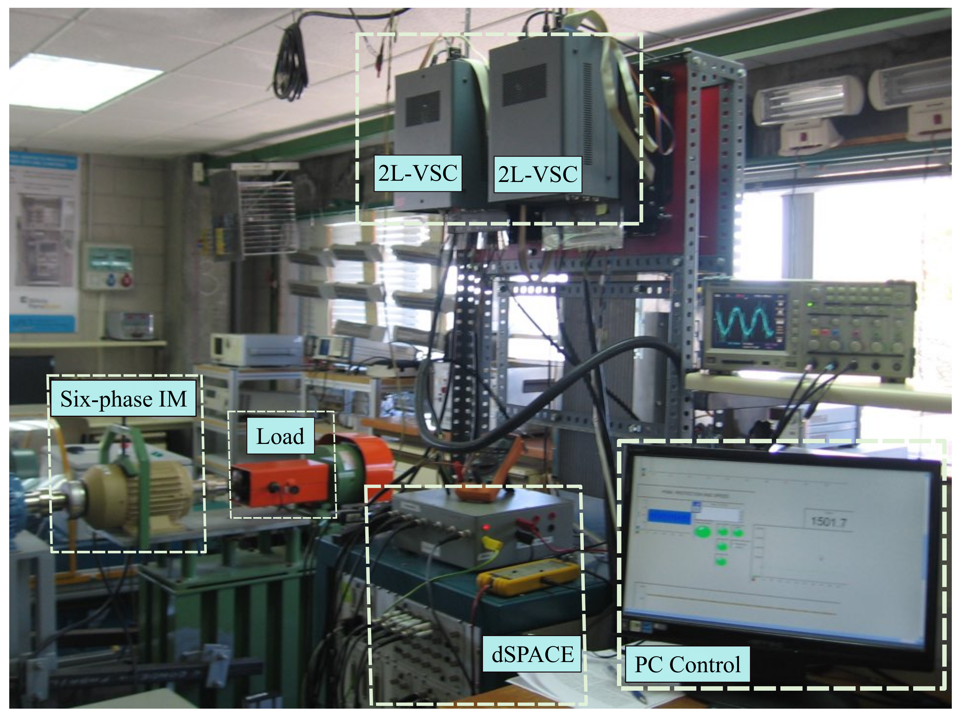
The current sensors LA 55-P s with a frequency bandwidth from dc up to 200 kHz was used in the practical tests. Based on a 16-bit A/D converter, we converted the measurement of the currents to digital. Moreover, the rotor speed was estimated from the position obtained with a 1024 ppr incremental encoder. Finally, a variable mechanical load acting on the used motor was introduced using a 5 HP eddy current brake. The equipment of the experimental setup is depicted in Figure 3.
The performance of the proposed discrete-time technique was analyzed in steady-state and transient conditions with a sampling frequency of 8 kHz. Three steady-state tests were performed respectively for two desired speeds 1000 rpm and 1500 rpm. In addition, two transient tests were performed with a change from 1000 rpm to 500 rpm and then a second step change from 500 rpm to 1000 rpm. In these tests, the desired d current was settled to 1 A. Moreover, a mechanical load was performed by fixing the eddy current brake at 1.65 A. Finally, to reduce the copper losses, the desired x y stator currents were set to 0 A. During these tests, the proposed controller gains were tuned manually while checking the control performance by trial and error and were finally selected as
Λ 1 = Λ 2 = diag ( 0.2 , 0.2 , 0.2 , 0.2 ) , γ i = 0.8 for i = 1 , , 4 ,
Q 1 = Q 3 = diag ( 0.7 , 0.7 , 0.7 , 0.7 ) , Q 2 = T s 1 diag ( 0.5 , 0.5 , 0.5 , 0.5 ) ,
Q 4 = T s 1 diag ( 0.3 , 0.3 , 0.3 , 0.3 ) .
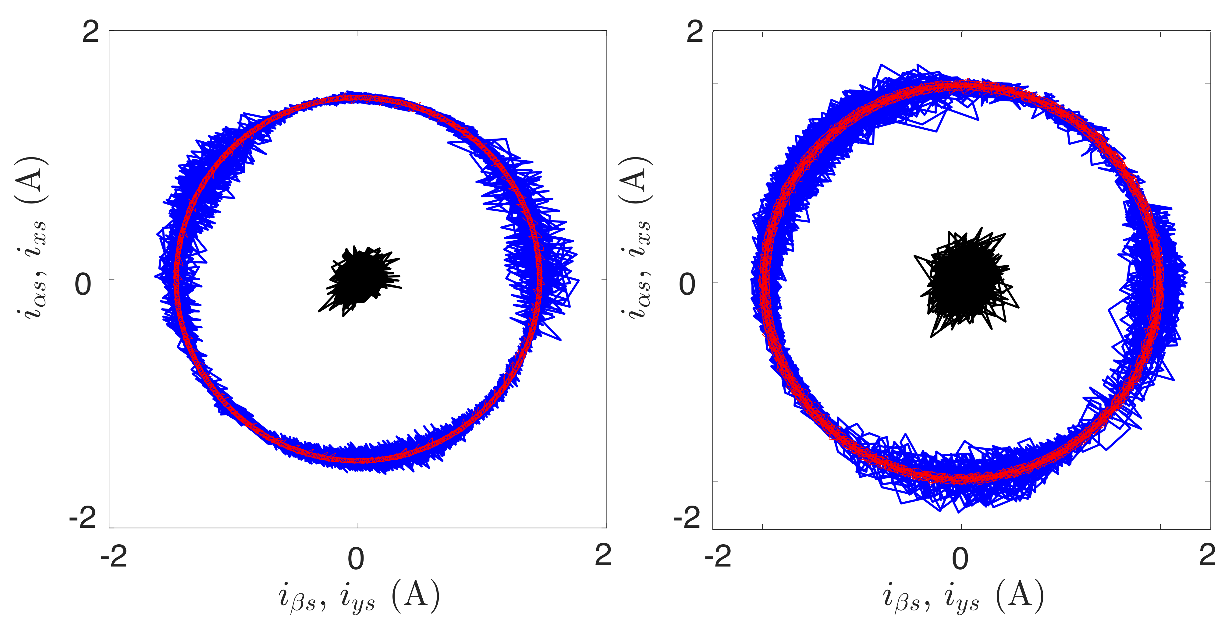
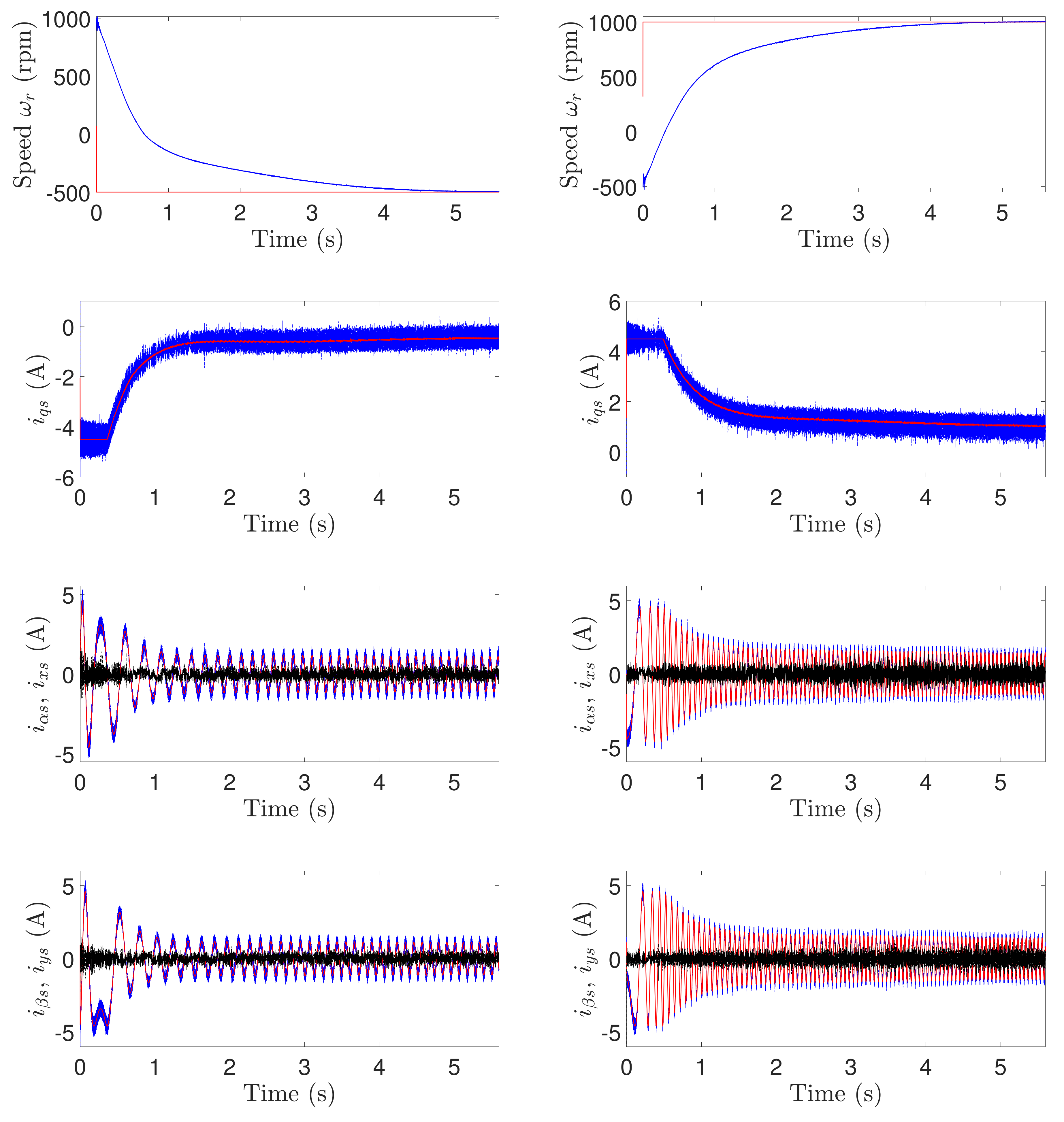
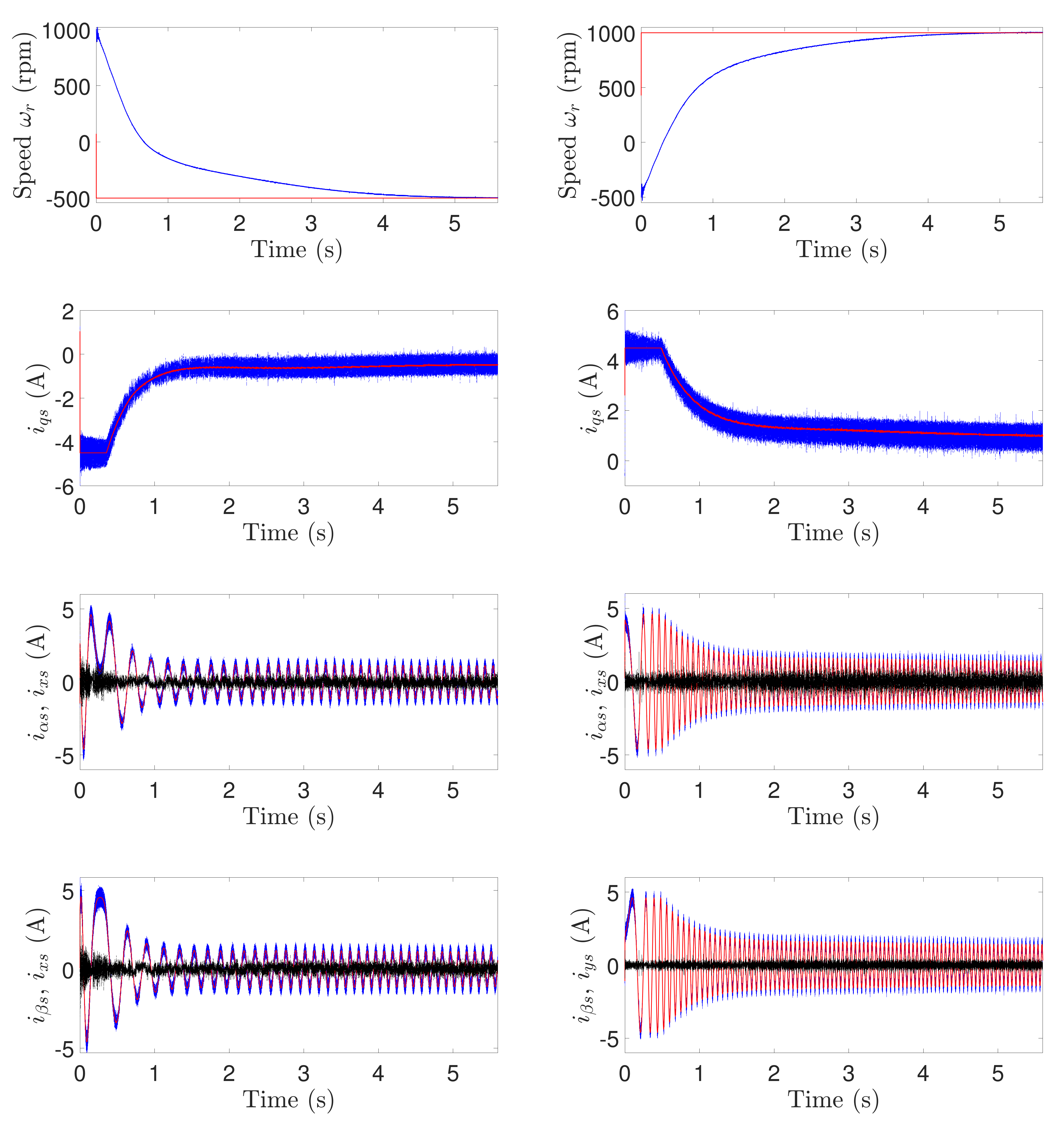
The results for the steady-state tests are depicted in Figure 4. In these figures as well as in Figure 5 and Figure 6, the blue signals represent the measured { q , α , β } stator currents, the red signals represent the desired { q , α , β } stator currents, while the black signals represent the measured { x , y } stator currents. The results in all the figures showed good tracking of the stator currents. Moreover, the results for the transient tests are shown in Figure 5. It is clear that the developed DTSTC ensures high-accuracy stator currents tracking in the α β , x y planes similar to that for the previous tests. Then, the same scenarios were performed while considering a 25 % variation in magnetizing inductance to demonstrate the insensitivity of the proposed method to parameter variations [29]. Notice that the variation in L m implies a variation in the whole dynamics since the coefficients C 1 , C 2 and C 3 are in terms of this inductance. The results shown in Figure 6 prove the robustness of the developed discrete method against parameter variations.
The performance of the developed discrete-time method was compared to the TDE-based DSMC [17] in steady state for two operating points, 1000 and 1500 (rpm), based on the Mean Squared Error (MSE) index defined for i = 1 , , 4 by
MSE ( X i ) = 1 N k = 1 N E i ( k ) 2 ,
where N is the total number of analyzed samples. The results of this comparative study are listed in Table 2 and show the obtained MSE values for the stator currents in α β and x y subspaces. The data show that better performances are obtained with the proposed algorithm over the existing TDE-based DSMC.

5. Conclusions

In this work, speed control based on an indirect rotor field-oriented control strategy with an inner DTSTC for the α β and the x y stator currents was developed. The proposed technique was supported by the TDE method to simply approximate the matched perturbations and the α β unmeasurable rotor current. The developed discrete terminal super-twisting rejects the nonlinearities caused by the estimation error and ensures accurate stator currents tracking and fast convergence of this latter to zero. The effectiveness of this discrete technique was shown in the theoretical development and experimental work conducted on a real asymmetrical six-phase induction motor. Indeed, the developed method produces excellent performances in steady state and transient state as well. Further research will be initiated to extend the development for a multiphase induction motor in faulty conditions since operating in faulty situations is one of the benefits of these machines. The extended work aims is to ensure high performance under fault condition without acting on the control law.

Author Contributions

Conceptualization, Y.K., M.S., and J.R.; methodology, Y.K., M.S., and J.R.; software, Y.K. and J.D.-G.; validation, J.D.-G.; formal analysis, Y.K., M.S., J.D.-G., and J.R.; investigation, Y.K. and M.S.; resources, J.D.-G.; data curation, J.D.-G.; writing—original draft preparation, Y.K. and M.S.; writing—review and editing, Y.K., M.S., J.D.-G., and J.R.; visualization, J.D.-G.; project administration, M.S. and J.D.-G. All authors have read and agreed to the published version of the manuscript.

Funding

This work was supported in part by the Spanish State Research Agency (AEI) under project PID2019-105612RB-I00/AEI/10.13039/501100011033.

Institutional Review Board Statement

Not applicable.

Informed Consent Statement

Not applicable.

Data Availability Statement

Not applicable.

Conflicts of Interest

The authors declare no conflict of interest.

Abbreviations

The following abbreviations are used in this manuscript:
dcDirect current
DQSMDiscrete-time quasi-sliding mode
DTSTCDiscrete terminal super-twisting control
IMInduction motor
MSEMean squared error
PIProportional-integral
QSMBQuasi sliding mode band
SMSliding mode
TDETime-delay estimation
VSCVoltage source converter

References

  1. Kali, Y.; Saad, M.; Rodas, J.; Mougharbel, I.; Benjelloun, K. Robust Control of a 6-Phase Induction Generator for Variable Speed Wind Energy Conversion System. In Proceedings of the 2020 5th International Conference on Renewable Energies for Developing Countries (REDEC), Marrakech, Morocco, 29–30 June 2020; pp. 1–6. [Google Scholar] [CrossRef]
  2. Yu, F.; Cheng, M.; Chau, K.; Li, F. Control and Performance Evaluation of Multiphase FSPM Motor in Low-Speed Region for Hybrid Electric Vehicles. Energies 2015, 8, 335. [Google Scholar] [CrossRef] [Green Version]
  3. Liu, Z.; Wu, J.; Hao, L. Coordinated and fault-tolerant control of tandem 15-phase induction motors in ship propulsion system. IET Electr. Power Appl. 2018, 12, 91–97. [Google Scholar] [CrossRef]
  4. Jung, E.; Yoo, H.; Sul, S.; Choi, H.; Choi, Y. A Nine-Phase Permanent-Magnet Motor Drive System for an Ultrahigh-Speed Elevator. IEEE Trans. Ind. Appl. 2012, 48, 987–995. [Google Scholar] [CrossRef]
  5. Barrero, F.; Duran, M.J. Recent Advances in the Design, Modeling, and Control of Multiphase Machines: Part I. IEEE Trans. Ind. Electron. 2016, 63, 449–458. [Google Scholar] [CrossRef]
  6. Duran, M.J.; Barrero, F. Recent Advances in the Design, Modeling, and Control of Multiphase Machines: Part II. IEEE Trans. Ind. Electron. 2016, 63, 459–468. [Google Scholar] [CrossRef]
  7. Levi, E. Advances in Converter Control and Innovative Exploitation of Additional Degrees of Freedom for Multiphase Machines. IEEE Trans. Ind. Electron. 2016, 63, 433–448. [Google Scholar] [CrossRef] [Green Version]
  8. Lim, C.; Levi, E.; Jones, M.; Rahim, N.; Hew, W.P. FCS-MPC based current control of a five-phase induction motor and its comparison with PI-PWM control. IEEE Trans. Ind. Electron. 2014, 61, 149–163. [Google Scholar] [CrossRef]
  9. Taheri, A.; Rahmati, A.; Kaboli, S. Efficiency improvement in DTC of six-phase induction machine by adaptive gradient descent of flux. IEEE Trans. Power Electron. 2012, 27, 1552–1562. [Google Scholar] [CrossRef]
  10. Rodas, J.; Barrero, F.; Arahal, M.R.; Martín, C.; Gregor, R. Online estimation of rotor variables in predictive current controllers: a case study using five-phase induction machines. IEEE Trans. Ind. Electron. 2016, 63, 5348–5356. [Google Scholar] [CrossRef]
  11. Rodas, J.; Martín, C.; Arahal, M.R.; Barrero, F.; Gregor, R. Influence of Covariance-Based ALS Methods in the Performance of Predictive Controllers with Rotor Current Estimation. IEEE Trans. Ind. Electron. 2017, 64, 2602–2607. [Google Scholar] [CrossRef]
  12. Elbarbary, Z.; Azeem, M.F.; Azazi, H.Z. Adaptive Fuzzy-Based IRFOC of Speed Sensorless Six-Phase Induction Motor Drive System. J. Circuits Syst. Comput. 2020, 29, 2050062. [Google Scholar] [CrossRef]
  13. Raja, D.; Ravi, G. Dynamic modeling and control of five phase SVPWM inverter fed induction motor drive with intelligent speed controller. J. Ambient. Intell. Humaniz. Comput. 2020, 1–11. [Google Scholar] [CrossRef]
  14. Kali, Y.; Rodas, J.; Saad, M.; Doval-Gandoy, J.; Gregor, R. Nonlinear Backstepping with Time Delay Estimation for Six-Phase Induction Machine. In Proceedings of the 2019 IEEE International Electric Machines Drives Conference (IEMDC), San Diego, CA, USA, 12–15 May 2019; pp. 1798–1804. [Google Scholar] [CrossRef]
  15. Morawiec, M.; Strankowski, P.; Lewicki, A.; Guziński, J.; Wilczyński, F. Feedback Control of Multiphase Induction Machines With Backstepping Technique. IEEE Trans. Ind. Electron. 2020, 67, 4305–4314. [Google Scholar] [CrossRef]
  16. Kali, Y.; Rodas, J.; Saad, M.; Gregor, R.; Doval-Gandoy, J.; Benjelloun, K. Comparative Study of Time Delay Estimation Based Optimal 1st and 2nd Order Sliding Mode for Current Regulation of Six-Phase Induction Machines. In Proceedings of the IECON 2019—45th Annual Conference of the IEEE Industrial Electronics Society, Lisbon, Portugal, 14–17 October 2019; Volume 1, pp. 6194–6199. [Google Scholar] [CrossRef]
  17. Kali, Y.; Ayala, M.; Rodas, J.; Saad, M.; Doval-Gandoy, J.; Gregor, R.; Benjelloun, K. Current Control of a Six-Phase Induction Machine Drive Based on Discrete-Time Sliding Mode with Time Delay Estimation. Energies 2019, 12, 170. [Google Scholar] [CrossRef] [Green Version]
  18. Kali, Y.; Saad, M.; Doval-Gandoy, J.; Rodas, J.; Benjelloun, K. Discrete sliding mode control based on exponential reaching law and time delay estimation for an asymmetrical six-phase induction machine drive. IET Electr. Power Appl. 2019, 13, 1660–1671. [Google Scholar] [CrossRef]
  19. Utkin, V.; Guldner, J.; Shi, J. Sliding Mode Control in Electromechanical Systems; Taylor-Francis: Boca Raton, FL, USA, 1999. [Google Scholar]
  20. Boiko, I.; Fridman, L. Analysis of Chattering in Continuous Sliding-mode Controllers. IEEE Trans. Autom. Control 2005, 50, 1442–1446. [Google Scholar] [CrossRef] [Green Version]
  21. Ma, H.; Wu, J.; Xiong, Z. A Novel Exponential Reaching Law of Discrete-Time Sliding-Mode Control. IEEE Trans. Ind. Electron. 2017, 64, 3840–3850. [Google Scholar] [CrossRef]
  22. Ma, H.; Li, Y.; Xiong, Z. Discrete-Time Sliding-Mode Control With Enhanced Power Reaching Law. IEEE Trans. Ind. Electron. 2019, 66, 4629–4638. [Google Scholar] [CrossRef]
  23. Zhang, J.; Shi, P.; Xia, Y.; Yang, H. Discrete-Time Sliding Mode Control With Disturbance Rejection. IEEE Trans. Ind. Electron. 2019, 66, 7967–7975. [Google Scholar] [CrossRef]
  24. Feng, Y.; Wen, X.; Xue, C.; Yu, X.; Han, F. Discrete-Time Quasi-Sliding Mode Control of Induction Motors. In Proceedings of the 2018 IEEE 8th Annual International Conference on CYBER Technology in Automation, Control, and Intelligent Systems (CYBER), Tianjin, China, 19–23 July 2018; pp. 1366–1369. [Google Scholar] [CrossRef]
  25. Kali, Y.; Ayala, M.; Rodas, J.; Saad, M.; Doval-Gandoy, J.; Gregor, R.; Benjelloun, K. Time Delay Estimation Based Discrete-Time Super-Twisting Current Control for a Six-Phase Induction Motor. IEEE Trans. Power Electron. 2020, 35, 12570–12580. [Google Scholar] [CrossRef]
  26. Harnefors, L.; Saarakkala, S.; Hinkkanen, M. Speed Control of Electrical Drives Using Classical Control Methods. IEEE Trans. Ind. Appl. 2013, 49, 889–898. [Google Scholar] [CrossRef]
  27. Kali, Y.; Saad, M.; Benjelloun, K.; Fatemi, A. Discrete-time second order sliding mode with time delay control for uncertain robot manipulators. Robot. Auton. Syst. 2017, 94, 53–60. [Google Scholar] [CrossRef]
  28. Poznyak, A.S. Chapter 12—Miscellaneous. In Advanced Mathematical Tools for Automatic Control Engineers: Deterministic Techniques; Poznyak, A.S., Ed.; Elsevier: Oxford, UK, 2008; pp. 213–227. [Google Scholar] [CrossRef]
  29. Delorme, L.; Ayala, M.; Rodas, J.; Gregor, R.; Gonzalez, O.; Doval-Gandoy, J. Comparison of the Effects on Stator Currents Between Continuous Model and Discrete Model of the Three-phase Induction Motor in the Presence of Electrical Parameter Variations. In Proceedings of the 2020 IEEE International Conference on Industrial Technology (ICIT), Buenos Aires, Argentina, 26–28 February 2020; pp. 151–156. [Google Scholar] [CrossRef]
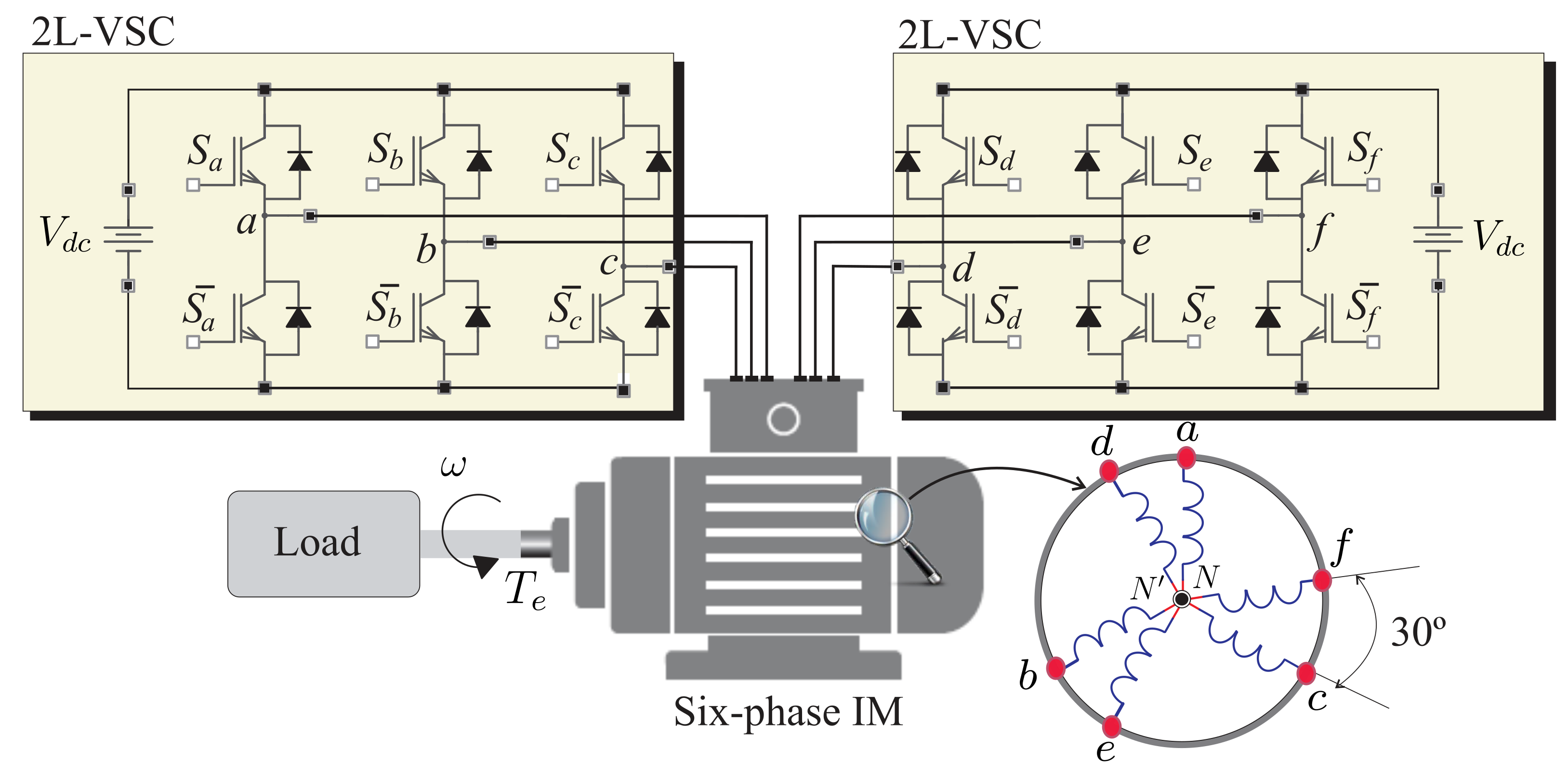
Figure 1. Studied six-phase IM powered by a six-leg VSC.
Energies 14 01339 g001
Figure 2. Scheme of the overall closed-loop control.
Energies 14 01339 g002
Figure 3. Experimental setup.
Energies 14 01339 g003
Figure 4. Steady-state response of { α , x , β , y } stator currents for two different desired rotor speed ω r d : results from left to right for 1000 and 1500 rpm.
Energies 14 01339 g004
Figure 5. Transient response of { q , α , x , β , y } stator currents for two different desired step rotor speeds ω r d : results from 1000 to −500 rpm in the left column and from −500 to 1000 rpm in the right column.
Energies 14 01339 g005
Figure 6. Transient response of { q , α , x , β , y } stator currents for two different desired step rotor speeds ω r d with a variation of 25% on the magnetizing inductance: results from 1000 to −500 rpm in the left column and from −500 to 1000 rpm in the right column.
Energies 14 01339 g006
Table 1. Six-phase IM parameters.
ParameterValueUnitParameterValueUnit
R r 7.0 Ω L s 654.4mH
R s 6.7 Ω J M 0.07kg·m 2
L l s 5.85mH B M 0.0004kg·m 2
L m 708.5mH V dc 400V
L r 626.8mH P p 1
Table 2. Quantitative comparison of the MSE of the { α , β , x , y } stator currents performance for two different rotor speed references.
Poposed DTSTC
ω r d (rpm) MSE i α s ( A ) MSE i β s ( A ) MSE i x s ( A ) MSE i y s ( A )
1000 0.29370.30210.23260.2280
1500 0.30000.30500.24910.2456
TDE-based DSMC [17]
ω r d (rpm) MSE i α s ( A ) MSE i β s ( A ) MSE i x s ( A ) MSE i y s ( A )
1000 0.08830.07950.04010.0457
1500 0.18130.16490.11070.1000
Publisher’s Note: MDPI stays neutral with regard to jurisdictional claims in published maps and institutional affiliations.