
Performance Assessment of Double Corrugated Tubes in a Tube-In-Shell Heat Exchanger


Abstract
:
1. Introduction
2. Materials and Methods
3. Results and Discussion
4. Conclusions
Author Contributions
Funding
Data Availability Statement
Conflicts of Interest
Appendix A
References
- Rozzi, S.; Massini, R.; Paciello, G.; Pagliarini, G.; Rainieri, S.; Trifirò, A. Heat treatment of fluid foods in a shell and tube heat exchanger: Comparison between smooth and helically corrugated wall tubes. J. Food Eng. 2007, 79, 249–254. [Google Scholar] [CrossRef]
- Carozza, A. Heat Exchangers in the Aviation Engineering. In Heat Exchangers—Advanced Features and Applications; InTech: London, UK, 2017; p. 38. [Google Scholar]
- Sundén, B. Computational heat transfer in heat exchangers. Heat Transf. Eng. 2007, 28, 895–897. [Google Scholar] [CrossRef]
- Kim, R.L.W.H. Principles of Enhanced Heat Transfer, 2nd ed.; Taylor and Francis group: Oxon, UK, 2006. [Google Scholar]
- Laohalertdecha, S.; Naphon, P.; Wongwises, S. A review of electrohydrodynamic enhancement of heat transfer. Renew. Sustain. Energy Rev. 2007, 11, 858–876. [Google Scholar] [CrossRef]
- Rainieri, S.; Bozzoli, F.; Pagliarini, G. Effect of a hydrophobic coating on the local heat transfer coefficient in forced convection under wet conditions. Exp. Heat Transf. 2009, 22, 163–177. [Google Scholar] [CrossRef]
- Zachár, A. Analysis of coiled-tube heat exchangers to improve heat transfer rate with spirally corrugated wall. Int. J. Heat Mass Transf. 2010, 53, 3928–3939. [Google Scholar] [CrossRef]
- Gee, D.L.; Webb, R.L. Forced convection heat transfer in helically rib-roughened tubes. Int. J. Heat Mass Transf. 1980, 23, 1127–1136. [Google Scholar] [CrossRef]
- Bozzoli, F.; Cattani, L.; Mocerino, A.; Rainieri, S.; Tougri, I.; Colaço, M.J. Characterisation of the heat transfer in displaced enhancement devices by means of inverse problem approach applied to IR images. Quant. Infrared Thermogr. J. 2019, 1–19. [Google Scholar] [CrossRef]
- Eiamsa-ard, S.; Thianpong, C.; Eiamsa-ard, P.; Promvonge, P. Thermal characteristics in a heat exchanger tube fitted with dual twisted tape elements in tandem. Int. Commun. Heat Mass Transf. 2010, 37, 39–46. [Google Scholar] [CrossRef]
- Bhuiya, M.M.K.; Chowdhury, M.S.U.; Shahabuddin, M.; Saha, M.; Memon, L.A. Thermal characteristics in a heat exchanger tube fitted with triple twisted tape inserts. Int. Commun. Heat Mass Transf. 2013, 48, 124–132. [Google Scholar] [CrossRef]
- Dagdevir, T.; Ozceyhan, V. An experimental study on heat transfer enhancement and flow characteristics of a tube with plain, perforated and dimpled twisted tape inserts. Int. J. Therm. Sci. 2021, 159. [Google Scholar] [CrossRef]
- Kareem, Z.S.; Jaafar, M.N.M.; Lazim, T.M.; Abdullah, S.; Abdulwahind, A.F. Heat transfer enhancement comparison in different tube shapes. Int. Rev. Model. Simulations 2015, 8, 232–240. [Google Scholar] [CrossRef]
- Kareem, Z.S.; Jaafar, M.N.M.; Lazim, T.M.; Abdullah, S.; Abdulwahid, A.F. Heat transfer enhancement in two-start spirally corrugated tube. Alexandria Eng. J. 2015, 54, 415–422. [Google Scholar] [CrossRef] [Green Version]
- Bozzoli, F.; Cattani, L.; Rainieri, S. Cross-helix corrugation: The optimal geometry for effective food thermal processing. Int. J. Heat Mass Transf. 2020, 147, 118874. [Google Scholar] [CrossRef]
- Penzel, M.; Zinecker, M.; Schubert, A.; Hackert-Oschätzchen, M.; Ludwig, A.; Adamczewski, A.; Schulz, A.; Lausberg, M. Investigation of Forced Convection in Pin Structured Cold Plates for Improved Heat Transfer and Heat Spreading. In Proceedings of the 9th World Conference on Experimental Heat Transfer, Fluid Mechanics and Thermodynamics, Iguazu Falls, Brazil, 11–15 June 2017. [Google Scholar]
- Kareem, Z.S.; Abdullah, S.; Lazim, T.M.; Jaafar, M.N.M.; Wahid, A.F.A. Heat transfer enhancement in three-start spirally corrugated tube: Experimental and numerical study. Chem. Eng. Sci. 2015, 134, 746–757. [Google Scholar] [CrossRef]
- Khaboshan, H.N.; Nazif, H.R. Investigation of heat transfer and pressure drop of turbulent flow in tubes with successive alternating wall deformation under constant wall temperature boundary conditions. J. Brazil. Soc. Mech. Sci. Eng. 2018, 40, 1–16. [Google Scholar] [CrossRef]
- Guo, Z.Y.; Li, D.Y.; Wang, B.X. A novel concept for convective heat transfer enhancement. Int. J. Heat Mass Transf. 1998, 41, 2221–2225. [Google Scholar] [CrossRef]
- Navickaitė, K.; Mocerino, A.; Cattani, L.; Bozzoli, F.; Bahl, C.; Liltrop, K.; Zhang, X.; Engelbrecht, K. Enhanced heat transfer in tubes based on vascular heat exchangers in fish: Experimental investigation. Int. J. Heat Mass Transf. 2019, 137, 192–203. [Google Scholar] [CrossRef]
- Navickaitė, K.; Cattani, L.; Bahl, C.R.H.; Engelbrecht, K. Elliptical double corrugated tubes for enhanced heat transfer. Int. J. Heat Mass Transf. 2019, 128, 363–377. [Google Scholar] [CrossRef]
- Prithiviraj, M.; Andrews, M.J. Three dimensional numerical simulation of shell-and-tube heat exchangers. Part I: Foundation and fluid mechanics. Numer. Heat Transf. Part A Appl. 1998, 33, 799–816. [Google Scholar] [CrossRef]
- Prithiviraj, M.; Andrews, M.J. Three dimensional numerical simulation of shell-and-tube heat exchangers. Part II: Heat transfer. Numer. Heat Transf. Part A Appl. 1998, 33, 817–828. [Google Scholar] [CrossRef]
- Kumar, V.; Saini, S.; Sharma, M.; Nigam, K.D.P. Pressure drop and heat transfer study in tube-in-tube helical heat exchanger. Chem. Eng. Sci. 2006, 61, 4403–4416. [Google Scholar] [CrossRef]
- Ozden, E.; Tari, I. Shell side CFD analysis of a small shell-and-tube heat exchanger. Energy Convers. Manag. 2010, 51, 1004–1014. [Google Scholar] [CrossRef]
- Shah, R.K.; Sekulic, D.P. Fundamentals of Heat Excanger Design; John Wiley & Sons: Hoboken, NJ, USA, 2003. [Google Scholar]
- Wegner, N.C.; Snodgrass, O.E.; Dewar, H.; Hyde, J.R. Whole-body endothermy in a mesopelagic fish, the opah, Lampris guttatus. Science 2015, 348, 786–789. [Google Scholar] [CrossRef]
- Dickson, K.A.; Graham, J.B. Evolution and consequences of endothermy in fishes. Physiol. Biochem. Zool. 2004, 77, 998–1018. [Google Scholar] [CrossRef] [PubMed]
- Navickaitė, K.; Mocerino, A.; Cattani, L.; Bozzoli, F.; Bahl, C.R.H.; Engelbrecht, K. Heat transfer in double corrugated tubes. In Proceedings of the 9th International Conference & Workshop REMOO-2019, Hong Kong, China, 16–18 April 2019. [Google Scholar]
- Frei, W. Which Turbulence Model Should I Choose for My CFD Application? 2017. Available online: https://www.comsol.de/blogs/which-turbulence-model-should-choose-cfd-application/ (accessed on 28 December 2020).
- Slater, J.W. Examining Spatial (Grid) Convergence. 2008. Available online: https://www.grc.nasa.gov/WWW/wind/valid/tutorial/spatconv.html (accessed on 1 February 2021).
- Kwasniewski, L. Application of grid convergence index in FE computation. Bull. Pol. Acad. Sci. Tech. Sci. 2013, 61, 123–128. [Google Scholar] [CrossRef] [Green Version]
- Hærvig, J.; Sørensen, K.; Condra, T.J. On the fully-developed heat transfer enhancing flow field in sinusoidally, spirally corrugated tubes using computational fluid dynamics. Int. J. Heat Mass Transf. 2017, 106, 1051–1062. [Google Scholar] [CrossRef] [Green Version]
- ComsolMultiphysics. Heat Transfer Module User’s Guide; Comsol: Burlington, MA, USA, 2015; pp. 1–222. [Google Scholar]
- Nellis, G.; Klein, S. Heat Transfer, 2nd ed.; Cambridge University Press: New York, NY, USA, 2009. [Google Scholar]
- Bergman, T.L.; Lavine, A.S.; Incropera, F.P.; Dewitt, D.P. Introduction to Heat Transfer, 6th ed.; John Wiley & Sons: Jefferson City, MO, USA, 2011. [Google Scholar]


| Constraint | Present Study | Ref. [25] |
|---|---|---|
| Shell diameter, D, mm | 100 | 90 |
| Tube diameter, Dh, mm | 20 | 20 |
| Number of tubes, Nt | 9 | 7 |
| Heat exchanger length, l, mm | 600 | 600 |
| Number of baffles, Nb | 6 | 6 |
| Central baffle spacing, Bs, mm | 90 | 86 |
| Baffle cut, Bc, % | 36 | 36 |
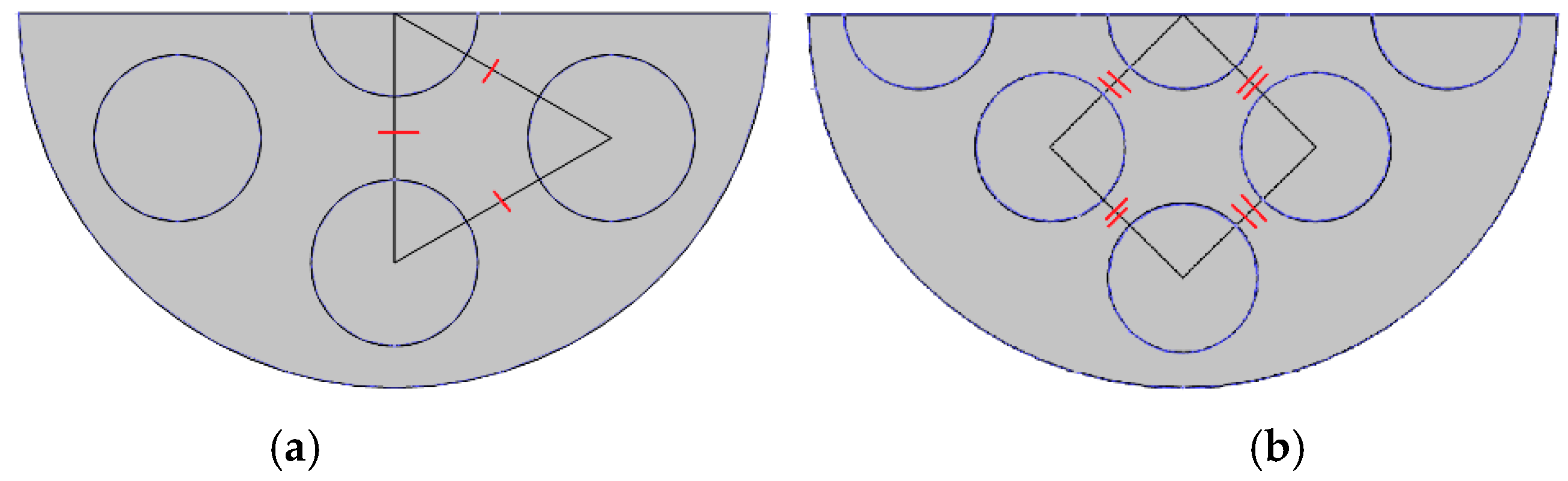
| Bundle geometry, pitch length, PL, mm | 45° rotated square, 25 mm | Triangle, 30 mm |
| Inlet/outlet diameter/length, l, mm | 20/20 | Not stated/not stated |
| Parameter | Value |
|---|---|
| Mass flow rate, , kg/s | 1 |
| Tube wall temperature, Tw, K | 450 |
| Inlet water temperature, Tin, K | 300 |
| Specific heat capacity of the tube material, cp, J/kg/K | 49 |
| Thermal conductivity of the tube material, k, W/m/K | 14.3 |
| Parameter | Ref. [25] | Present Study, Full Model | |Difference w. r. t. Ref. [25]|, % | Present Study, Model with Symmetry BC | |Difference w. r. t. Ref. [25]|, % |
|---|---|---|---|---|---|
| Standard k-ε turbulence model | |||||
| Outlet temperature, To, K | 330.00 | 335.13 | 1.55 | 335.32 | 1.61 |
| Total heat transfer rate, q, kW | 138.32 | 146.64 | 6.02 | 147.37 | 6.54 |
| Realisable k-ε turbulence model | |||||
| Outlet temperature, To, K | 330.18 | 335.28 | 1.54 | 334.48 | 1.30 |
| Total heat transfer rate, q, kW | 131.79 | 148.07 | 12.35 | 143.78 | 9.10 |
| SST | |||||
| Outlet temperature, To, K | - | 332.97 | - | 333.39 | - |
| Total heat transfer rate, q, kW | - | 138.78 | - | 141.08 | - |
| Name of HEX | |GCI1–2| | |GCI2–3| | Asymptotic Convergence (Equation (8)) | True Value, qt, kW | No. of Mesh el. |
|---|---|---|---|---|---|
| Straight | 0.0204 | 0.0047 | 0.9874 | 157.95 | 771,383 |
| EAC AR16 K15D | 0.0632 | 0.0231 | 0.9695 | 182.75 | 1,358,884 |
| EAC AR16 K30D | 0.0547 | 0.0988 | 0.9631 | 152.74 | 796,612 |
| EAC AR20 K15D | 0.0583 | 0.0395 | 0.9854 | 200.98 | 2,089,290 |
| EAC AR20 K30D | 0.0118 | 0.0116 | 0.9906 | 367.69 | 2,320,316 |
| EDH AR16 K15D | 0.0467 | 0.0267 | 0.9846 | 202.96 | 2,660,826 |
| EDH AR16 K30D | 0.0037 | 0.0130 | 0.9925 | 169.43 | 1,518,398 |
| EDH AR20 K15D | 0.0739 | 0.1410 | 0.9430 | 177.38 | 1,194,197 |
| EDH AR20 K30D | 0.0473 | 0.0817 | 0.9714 | 143.57 | 1,955,813 |
| Tube Name | Mass Flow Rate, , kg/s | Outlet Temperature, To, K | Net Heat Transfer, q, kW | NTU | Pressure Drop, Δp, kPa |
|---|---|---|---|---|---|
| Straight | 1.0 | 338.17 | 160.57 | 0.55 | 22.94 |
| 2.0 | 334.82 | 293.14 | 0.50 | 88.90 | |
| 3.0 | 333.80 | 426.91 | 0.48 | 197.16 | |
| 4.0 | 333.30 | 560.74 | 0.47 | 346.90 | |
| EAC AR16 K15D | 1.0 | 343.01 | 179.43 | 0.63 | 20.69 |
| 2.0 | 338.23 | 319.27 | 0.55 | 80.14 | |
| 3.0 | 336.84 | 461.52 | 0.53 | 177.70 | |
| 4.0 | 336.20 | 604.78 | 0.52 | 312.86 | |
| EAC AR16 K30D | 1.0 | 339.56 | 165.85 | 0.58 | 18.99 |
| 2.0 | 335.56 | 298.42 | 0.51 | 73.88 | |
| 3.0 | 334.40 | 433.15 | 0.49 | 164.05 | |
| 4.0 | 333.86 | 568.51 | 0.48 | 288.49 | |
| EAC AR20 K15D | 1.0 | 346.76 | 194.83 | 0.70 | 19.74 |
| 2.0 | 341.55 | 346.57 | 0.61 | 77.13 | |
| 3.0 | 339.77 | 497.70 | 0.58 | 171.66 | |
| 4.0 | 338.99 | 650.68 | 0.57 | 302.89 | |
| EAC AR20 K30D | 1.0 | 345.50 | 190.52 | 0.68 | 17.63 |
| 2.0 | 341.16 | 344.88 | 0.60 | 69.13 | |
| 3.0 | 339.76 | 499.87 | 0.58 | 153.93 | |
| 4.0 | 339.14 | 656.25 | 0.57 | 271.04 | |
| EDH AR16 K15D | 1.0 | 347.72 | 198.72 | 0.71 | 20.40 |
| 2.0 | 342.89 | 357.47 | 0.62 | 78.98 | |
| 3.0 | 341.32 | 516.67 | 0.60 | 175.37 | |
| 4.0 | 340.74 | 679.28 | 0.59 | 309.54 | |
| EDH AR16 K30D | 1.0 | 340.70 | 171.22 | 0.60 | 19.83 |
| 2.0 | 336.01 | 303.30 | 0.52 | 77.41 | |
| 3.0 | 334.60 | 437.24 | 0.50 | 172.14 | |
| 4.0 | 333.97 | 572.40 | 0.49 | 302.26 | |
| EDH AR20 K15D | 1.0 | 348.07 | 199.93 | 0.73 | 20.47 |
| 2.0 | 342.59 | 354.65 | 0.63 | 79.03 | |
| 3.0 | 340.67 | 508.22 | 0.60 | 175.41 | |
| 4.0 | 339.80 | 663.19 | 0.58 | 308.84 | |
| EDH AR20 K30D | 1.0 | 336.33 | 153.61 | 0.54 | 17.17 |
| 2.0 | 335.08 | 296.76 | 0.52 | 67.36 | |
| 3.0 | 334.55 | 438.40 | 0.51 | 150.24 | |
| 4.0 | 334.25 | 579.60 | 0.51 | 265.29 |
Publisher’s Note: MDPI stays neutral with regard to jurisdictional claims in published maps and institutional affiliations. |
© 2021 by the authors. Licensee MDPI, Basel, Switzerland. This article is an open access article distributed under the terms and conditions of the Creative Commons Attribution (CC BY) license (http://creativecommons.org/licenses/by/4.0/).
Share and Cite
Navickaitė, K.; Penzel, M.; Bahl, C.R.H.; Engelbrecht, K. Performance Assessment of Double Corrugated Tubes in a Tube-In-Shell Heat Exchanger. Energies 2021, 14, 1343. https://doi.org/10.3390/en14051343
Navickaitė K, Penzel M, Bahl CRH, Engelbrecht K. Performance Assessment of Double Corrugated Tubes in a Tube-In-Shell Heat Exchanger. Energies. 2021; 14(5):1343. https://doi.org/10.3390/en14051343
Chicago/Turabian StyleNavickaitė, Kristina, Michael Penzel, Christian R. H. Bahl, and Kurt Engelbrecht. 2021. "Performance Assessment of Double Corrugated Tubes in a Tube-In-Shell Heat Exchanger" Energies 14, no. 5: 1343. https://doi.org/10.3390/en14051343
APA StyleNavickaitė, K., Penzel, M., Bahl, C. R. H., & Engelbrecht, K. (2021). Performance Assessment of Double Corrugated Tubes in a Tube-In-Shell Heat Exchanger. Energies, 14(5), 1343. https://doi.org/10.3390/en14051343