Abstract
Gas turbine inlet air-cooling (TIAC) is an established technology for augmenting gas turbine output and efficiency, especially in hot regions. TIAC using evaporative cooling is suitable for hot, dry regions; however, the cooling is limited by the ambient wet-bulb temperature. This study investigates two-stage evaporative TIAC under the harsh weather of Riyadh city. The two-stage evaporative TIAC system consists of indirect and direct evaporative stages. In the indirect stage, air is precooled using water cooled in a cooling tower. In the direct stage, adiabatic saturation cools the air. This investigation was conducted for the GE 7001EA gas turbine model. Thermoflex software was used to simulate the GE 7001EA gas turbine using different TIAC systems including evaporative, two-stage evaporative, hybrid absorption refrigeration evaporative and hybrid vapor-compression refrigeration evaporative cooling systems. Comparisons of different performance parameters of gas turbines were conducted. The added annual profit and payback period were estimated for different TIAC systems.
1. Introduction
Gas turbine power plants have relatively low cost, require less space and are quick to be commissioned. Gas turbines (Figure 1) have a compressor that draws air in and compresses it and a fuel combustor that heats the compressed air. Combustion products at high temperatures and pressure are passed through the turbine, where they expand and develop motive force for turning the turbine rotor.
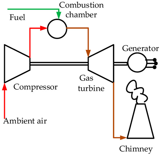
Figure 1.
Simple cycle gas turbine unit.
The capacity and efficiency of gas turbine systems highly depend on ambient temperature and pressure. In a relatively hot climate, such as in the Kingdom of Saudi Arabia (KSA), turbine capacities can fluctuate as much as 20% between summer and winter, because a gas turbine is a constant volumetric flow rate machine. The output of a gas turbine decreases as the air mass flow rate decreases owing to an increase in the ambient temperature. The power output of the GE 7001EA gas turbine can fall from 84.4 MW at 15 °C to 69.0 MW at an ambient temperature of 45 °C. Consequently, cooling the incoming air can increase the gas turbine power output by 20%.
Air at the compressor inlet can be cooled using evaporative cooling and mechanical or thermal refrigeration. The evaporative cooling system (Figure 2) is desirable for conventional cooling techniques owing to the low cost and the low energy needed to operate the system. Using either a wetted medium or a water spray system, the cooling effect in evaporative cooling depends solely on the difference between the ambient dry and wet-bulb temperatures. To cool the air below ambient wet-bulb temperature, a multistage evaporative system, introduced by [1], can be used (Figure 3). In the first stage, a cooling tower cools the water used to precool the air in a heat exchanger. In the second stage, direct evaporative cooling is used to further cool the air.
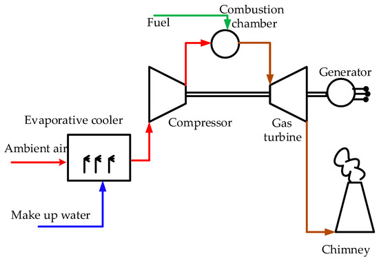
Figure 2.
Gas turbine with evaporative inlet cooling.
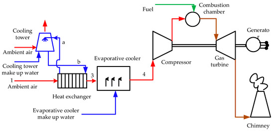
Figure 3.
Gas turbine with two-stage evaporative inlet cooling.
Vapor-compression or absorption refrigeration systems commonly provide refrigeration. The vapor-compression refrigeration system will be driven using work from the turbine at the expense of a power output increase because of the inlet air cooling. However, vapor-compression refrigeration is typically characterized by a relatively high initial cost and relatively high power consumption, compared with evaporative cooling, which has relatively low power consumption. For a medium-sized gas turbine (typically in the output range of 20–60 MW), exhaust heat is suitable in quantities and temperatures for power absorption refrigeration cycle systems.
To reduce refrigeration capacity and work or heat needed to operate the inlet air-cooling system, hybrid refrigeration evaporative cooling, similar to that shown in Figure 4 and Figure 5, can be used. As shown in Figure 4 and Figure 5, an absorption or a vapor-compression refrigeration system is used to produce chilled water to precool the air in a heat exchanger before using evaporative cooling. Both systems condensers’ water is cooled using cooling towers. Al-Aansary et al. [2] introduced a hybrid turbine inlet cooling system combining the benefits of evaporative cooling with vapor-compression refrigeration. This system is based on a two-step cooling process, in which mechanical vapor-compression first precools the air which is further cooled using evaporative cooling.
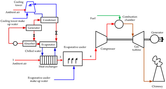
Figure 4.
Gas turbine with evaporative-absorption refrigeration inlet cooling.
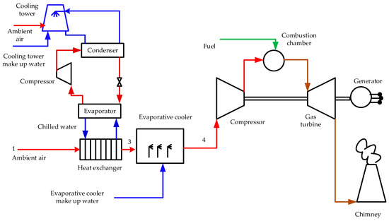
Figure 5.
Gas turbine with evaporative vapor-compression refrigeration inlet cooling.
Gas turbine inlet air cooling (TIAC) is a well-known technology that is used to improve gas turbine performance [1,2,3,4], where gas turbine power increases at a low cost per kW. Various approaches for cooling the turbine inlet air have been used. Gas turbines have ambient temperature sensitivity, where both the capacity and efficiency decrease as the ambient temperature increases. The compressor section of the gas turbine’s power demand is proportional to the absolute temperature of the inlet air. The compressor mass flow rate capacity is proportional to the air density at the compressor inlet, which is inversely proportional to the absolute temperature. Therefore, high ambient temperature negatively affects both the capacity and efficiency of the turbine.
Gas turbines are rated at ISO conditions, 15 °C (59 °F), which is approximately the global average temperature. Single or simple cycle turbines working at full load in KSA have an efficiency of 22–28% [5].
Various approaches for cooling turbine inlet air have been implemented. Al-Ibrahim et al. [6] and Deng et al. [7] conducted extensive reviews of gas turbine inlet air cooling systems.
Hot dry air can be cooled using water evaporation. For turbine inlet cooling, this can be accomplished either with wetted media or using water spray systems. Both evaporative cooling techniques share the attribute that the difference between dry-bulb and wet-bulb temperatures limit cooling. The biggest advantage of evaporative cooling is the low installation cost. Typically, this system’s weakness is water availability, particularly in dry regions.
Investigators, including [1,2,3,4,8,9,10,11,12,13], studied evaporative gas turbine inlet cooling. Ali et al. [3] and Zeitoun et al. [4] simulated evaporative cooling for the GE7001EA gas turbine using Thermoflex software for different evaporation techniques. The results showed that the net power output could reach 12%, but the efficiency increased only by a maximum of ~2.5%.
Alhazmy and Najar [8] reported that evaporative cooling could boost the power output and enhance the efficiency of gas turbines less expensively as compared to the cost of chilling systems. Although the performance of evaporative coolers depends highly on ambient conditions, they operate efficiently under hot and dry conditions. The analysis of Alhazmy and Najar [8] has shown that evaporative cooling reduces the temperature of incoming air by 3–15 °C, enhancing the power by 1–7% and improving the efficiency by 3%. Gas turbine evaporative inlet cooling, according to Wang and Braquet [9], indicated a potential of 10% enhancement in power output in warm, dry conditions. Wang and Braquet [9] reported that the installation cost of the evaporative inlet cooling system was 57% lower in cost than buying new gas turbines.
Ehyaei et al. [10,13] investigated the effect of fogging on gas turbine efficiencies and emissions and social cost. The model of [10] indicated that the first- and second-law efficiencies increased from 5.5% to 7%, and the social cost of air pollution dropped by 4%. Mahto and Pal [11] studied the effect of fogging on combined cycles of different configurations and concluded that the optimum configuration was the combined cycle with a triple-pressure heat recovery steam generator. Carmona [12] conducted thermodynamic and economic investigations using evaporative cooling in hot humid regions. According to [12], evaporative cooling can improve the performance of gas turbines, even in tropical areas. Saghafifar et al. [14] recommended using the Maisotsenko cooler for gas TIAC in hot and humid climates, where gas turbine waste heat was used for desiccant regeneration.
Absorption and vapor-compression refrigeration can also be used for the compressor inlet cooling by passing relatively hot ambient air over a coil cooled by chilled water (or brine). The main advantage of such systems is that air can be cooled to temperatures below the wet-bulb temperature. The use of vapor-compression or absorption refrigeration in gas TIAC was investigated by [15,16,17,18,19,20,21,22,23,24]. Erickson et al. [15] reported that a 300-refrigeration ton aqua-ammonia refrigeration unit was required to cool the inlet of a 5-MW gas turbine from 35 °C to 5 °C. Cooling increases the power output by 1 MW, and the added power is at a marginal efficiency of 39%, compared with 29% for the base turbine power. Turbine power increases at a lower cost per kilowatt than the turbine alone and improves the heat rate [16,17].
According to Ondryas et al. [18], gas turbine power augmentation using inlet air chilling can be used to boost peak power at high ambient temperatures. Ondryas et al. [18] concluded that the benefits from on-peak power production can outweigh the cost of the chillers’ expensive equipment. According to Alhazmy et al. [19], the mechanical refrigeration used in turbine inlet cooling improved power output but appreciably dropped in thermal efficiency. Marzouk and Hanafi [20] reported that using chillers could increase the annual power gained by 36%, compared with evaporative cooling, while the net cash flow was 16% lower than evaporative cooling. Kodituwakku [21] investigated the use of a two-stage absorption system to cool the GE MS5001R turbine. The cost of the exhaust-driven absorption chiller system was $736 per ton of refrigeration, with a payback period of 11 years. Mohapatra and Sanjay [22] reported that vapor-compression refrigeration inlet air cooling could improve the plant-specific work by 18.4% and efficiency by 4.18%, compared with 10.48% and 4.6%, respectively, for evaporative cooling. However, evaporative inlet air cooling might be preferred over vapor-compression cooling for higher plant efficiency. Barakat et al. [23] investigated the use of geothermal energy in inlet air cooling of gas turbines. As reported by [23], the output power and thermal efficiency increased by 9% and 4.8%, respectively, with a payback period of 1.2 years. The comparison of El-Shazly et al. [24] indicated that the absorption chiller achieved an augmentation of 25.47% and 33.66% in power and efficiency, respectively, while the evaporative cooler provides only an increase of 5.56% and 1.55% in power and efficiency, respectively.
The effect of a combined cycle inlet cooling using absorption and vapor-compression refrigeration was investigated by [25,26]. Yang et al. [25] concluded that absorption chilling was preferable in ambient temperature zones (25 °C) and with a relative humidity higher than 40%. Mohapatra and Sanjay [26] conducted a comparison study to investigate the impact of inlet air cooling using vapor-compression and absorption refrigeration. It was observed by [26] that the benefits of using absorption refrigeration were superior to vapor-compression refrigeration. As reported by [26], the optimum value of the compressor inlet temperature was 20 °C for both absorption and vapor-compression refrigeration schemes.
Thermal energy storage (TES) systems incorporated in inlet air-cooling systems of gas turbines were investigated by [27,28]. TES systems are based on chilled water or ice thermal storage charged during low-load nighttime using mechanical chillers. Chilled water or ice is used on the hot day during high-load hours to cool inlet air to the compressor.
The thermo-economic analysis of [29] indicated that the payback period of using media evaporative, fogging and absorption refrigeration TIAC systems were 1.4, 1.14 and 5.7 years, respectively. The economic analysis of [20] revealed that the payback period were 0.66 and 3.3 years for evaporative and vapor compression refrigeration TIAC systems, respectively.
Al-Ansary et al. [2] and Dizaji et al. [30] investigated hybrid inlet cooling systems. As reported by Al-Ansary et al. [2], hybrid inlet cooling systems typically required significantly smaller amounts of makeup water than conventional evaporative cooling systems because the amount of water that must be added initially is significantly lower. When compared with mechanical vapor-compression, the hybrid system cools the air to an intermediate temperature, significantly lowering the required chilling/refrigerating capacity. Thus, the required chillers can have smaller comparative capacities and consume relatively less power.
Two-stage evaporative cooling is a new technology used in air conditioning applications. This technology can cool ambient air below its wet bulb temperature. In this investigation, the feasibility of the two-stage evaporative cooling technique as a TIAC system was examined. This study focused on investigating the performance of a real gas turbine incorporated with a two-stage evaporative TIAC system (Figure 3) under the hot dry weather conditions of Riyadh city. Comparisons of the proposed system and evaporative and hybrid refrigeration evaporative TIAC systems (Figure 2,Figure 4 and Figure 5) were conducted.
2. Gas Turbine Simulation
Thermoflex (part of THERMOFLOW software) is a well-known simulation software with a graphical interface, allowing the assembly of a thermal system model from icons representing more than 175 components. The program covers both the design and off-design simulation of real systems and models all types of power plants, including gas turbine, combined and conventional steam cycles. The simulation procedure is presented in [3,4].
The software was validated by simulating ISO [3,4] and the commission conditions of the GE turbine (Figure 5). Table 1 lists the comparison data showing the high capability of Thermoflex software to simulate real gas turbines.

Table 1.
Comparison between Thermoflex prediction and contract conditions of a GE 7001EA gas turbine.
3. Investigated Gas Turbine Inlet Cooling Systems
GE 7001EA gas turbine performances with and without different inlet cooling techniques, including evaporative cooling (Figure 2), two-stage evaporative cooling (Figure 3), hybrid absorption refrigeration evaporative cooling (Figure 4) and hybrid vapor-compression refrigeration evaporative cooling (Figure 5), were simulated for the months of the year under the weather conditions of Riyadh (Table 2). In this investigation, the performances between the gas turbine with the mentioned inlet cooling techniques and the same gas turbine without inlet cooling are compared (Figure 6).
Table 2.
Average weather conditions of Riyadh [31].

Figure 6.
Thermoflex model of the GE 7001EA gas turbine.
Figure 7 shows a schematic of the turbine and inlet cooling system as presented in Thermoflex for gas turbines with evaporative inlet cooling (Figure 2). The surrounding ambient air (7) is cooled from state 4 to state 2, as it is humidified in the evaporative cooler (5) using a water source (8). The temperature at the evaporative cooler exit, state 2, is limited by the wet-bulb temperature of the ambient air.
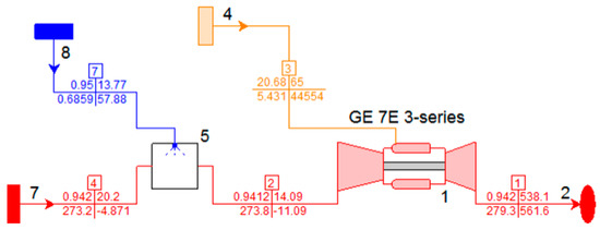
Figure 7.
Gas turbine with evaporative inlet cooling.
Given the benefits of the two-stage cooling cycle, it would be desirable to provide a two-stage evaporative cooling method for turbine inlet cooling to reduce the inlet air dry-bulb temperature below the inlet air wet-bulb temperature. Figure 8 shows a schematic of the turbine and inlet cooling system presented in Thermoflex for a gas turbine with two-stage evaporative inlet cooling introduced by [1] (Figure 3). The surrounding ambient air (7) is precooled from state 6 to state 5 in the heat exchanger (9). The air cooling is completed from state 5 to state 2, as it is humidified in the evaporative cooler (5) using a water source (8). The cooling tower (10) cools the water required for the heat exchanger (9).
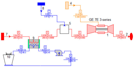
Figure 8.
Gas turbine with two-stage evaporative inlet cooling.
Figure 9 shows a schematic of the turbine and inlet cooling system presented in Thermoflex for a gas turbine with hybrid absorption refrigeration evaporative inlet cooling (Figure 4). The surrounding ambient air (7) is precooled from state 6 to state 5 in the heat exchanger (6). The air cooling is completed from state 5 to state 2, as it is humidified in the evaporative cooler (5) using a water source (8). The absorption chiller (3) cools the water needed for the heat exchanger (6). The generator of the absorption chiller (3) was assumed to operate using a hot water source (12) of 100 °C, which will be heated using gas turbine exhaust gases. The design absorption coefficient of the chiller’s performance was assumed as 0.67. The maximum temperature rise in the chilled water in the heat exchanger (6) was assumed as 7 °C. This hot water is heated using gas turbine exhaust gases. The condenser of the absorption chiller (3) is water-cooled using a cooling tower (10).
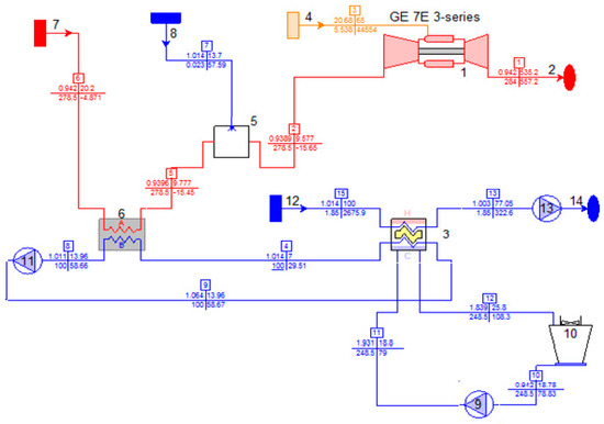
Figure 9.
Gas turbine with hybrid absorption refrigeration evaporative inlet cooling.
Figure 10 shows a schematic of the turbine and inlet cooling system presented in Thermoflex for a gas turbine with hybrid vapor-compression refrigeration evaporative inlet cooling (Figure 5). The surrounding ambient air (7) is precooled from state 1 to state 2 in the heat exchanger (6). The air cooling is completed from state 2 to state 3, as it is humidified in the evaporative cooler (3) using a water source (5). The vapor-compression chiller (12), an electrically driven system using gas turbine output, cools the water needed for the heat exchanger (6). The maximum temperature rise in the chilled water in the heat exchanger (6) was assumed as 7 °C. The design coefficient of the chiller’s performance was assumed as 3. The condenser of the vapor-compression chiller (12) is water-cooled using a cooling tower (10).
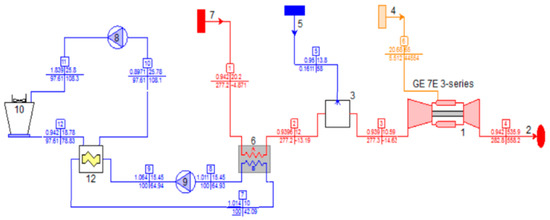
Figure 10.
Gas turbine with hybrid vapor-compression refrigeration evaporative inlet cooling.
For the above cases, the saturation efficiency of evaporative coolers was assumed as 95%, and the heat exchanger minimum pinch point was assumed as 2 °C.
4. Simulation Results and Discussions
The simulation of the above cases was conducted for the GE 7001EA gas turbine in Riyadh. Figure 11 shows the net output power of the gas turbine with and without different inlet cooling techniques. The results indicate that the turbine power, ISO-rated 84 MW, fluctuates between 64.6 MW in June and 75.9 MW in December. For evaporative inlet cooling, the turbine power fluctuates between 74.5 and 78.8 MW. For two-stage evaporative inlet cooling, the turbine power fluctuates between 76.5 and 78.8 MW. For hybrid absorption evaporative inlet cooling, the turbine power fluctuates between 76.5 and 81 MW. For hybrid vapor-compression evaporative inlet cooling, the turbine power fluctuates between 76.5 and 80.6 MW. Figure 12 shows the monthly percentage increase in the turbine’s net power output for the different cooling techniques, referenced to the turbine without inlet cooling. The data in Figure 12 show that the augmentation in the turbine’s output can reach 20% in the summer. The two-stage evaporative inlet cooling system (Figure 12) performs better in June, July and August than the other techniques. Figure 13 shows the annual added electric energy owing to inlet cooling, compared with the uncooled turbine.
where Ewic and Eic are the annual energy generated without and with an inlet cooling system, respectively. The annual added energy percentages are 10 % for the evaporative cooling, 11.3 % for the two stage evaporative cooling, 12.5 % for the hybrid absorption and 12.4 % for the hybrid vapor compression TIAC systems. The two hybrid refrigeration methods are better than the two evaporative methods owing to their satisfactory performance in the winter.
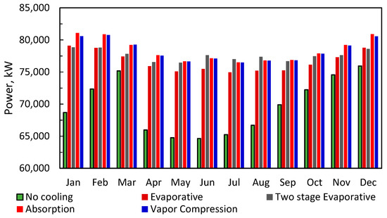
Figure 11.
Effect of inlet cooling on turbine power output.
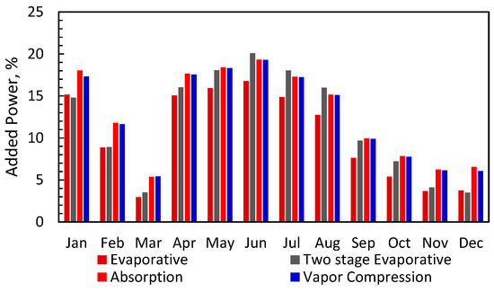
Figure 12.
Added power output.
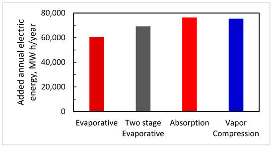
Figure 13.
Added annual electric energy (MW h/year).
Figure 14 and Figure 15 show the net heat rate and turbine net efficiency based on network, respectively. Figure 16 shows the percentage increase in gas turbine efficiency with inlet cooling systems compared with gas turbines without inlet cooling system.
where ηwic and ηic are efficiencies without and with an inlet cooling system, respectively. The gas turbine efficiency with the inlet cooling system can be increased by 4.3% in the summer.
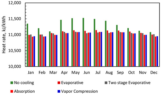
Figure 14.
Effect of inlet cooling on turbine heat rate.
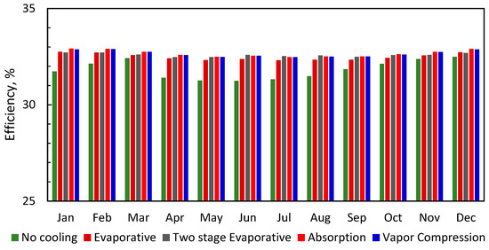
Figure 15.
Effect of inlet cooling on gas turbine efficiency.
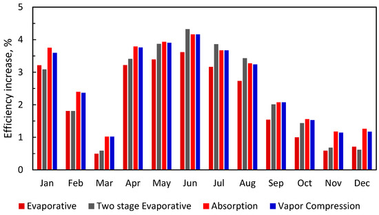
Figure 16.
Percentage increase in gas turbine efficiency.
Water consumption for inlet cooling systems is critical in dry regions. For simulated inlet cooling systems, water is needed to operate evaporative cooling sections and cooling towers. Figure 17 and Figure 18 show the total water consumption using evaporative coolers and cooling towers at daily and yearly rates. The two-stage evaporative cooling system consumes less water than the hybrid absorption and vapor-compression systems. The cooling tower of the absorption refrigeration system consumes larger amounts of water than other systems to release high condenser heat to the surrounding. The hybrid absorption system needs 80%, 130% and 240% more water than the hybrid vapor-compression, the two-stage evaporative and the evaporative TIAC systems, respectively.
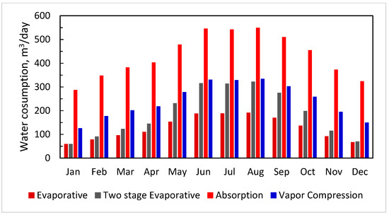
Figure 17.
Water consumption of different inlet cooling systems.
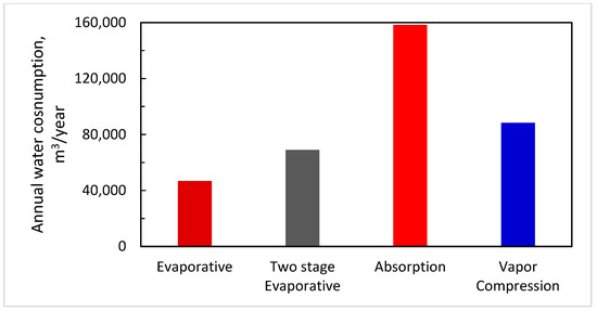
Figure 18.
Annual water consumption of different inlet cooling systems.
Figure 19 shows that the fuel consumption of the gas turbine with inlet cooling systems increases, compared with the gas turbine without a cooling system. The increase in fuel consumption is related to the increase in the compressor airflow rate owing to inlet cooling. Figure 20 shows the annual increase in fuel consumption.
where mf,wic and mf,ic are annual fuel consumption without and with inlet cooling systems, respectively.
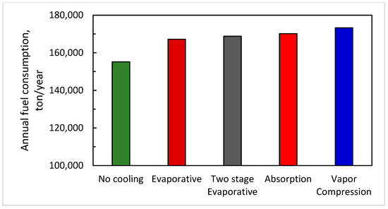
Figure 19.
Annual fuel consumption of different inlet cooling systems.
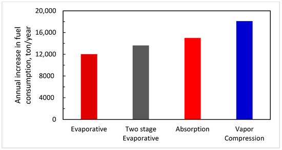
Figure 20.
Annual increase in fuel consumption of different cooling systems.
5. Economic Analysis
The feasibility of the investigated inlet cooling systems depends on their annual total cost. The total costs include installation and operating costs. Regarding operating cost, the added annual profit AAP because of using inlet cooling systems can be estimated from
where Sa is the added annual sale value of added energy and Ca is the added annual fuel and water costs. The added annual sale value of added energy because of using inlet cooling systems can be estimated from
The current tariff of electricity in Saudi Arabia is Tae = 0.048 $/kWh [32]. The added annual cost because of using inlet cooling systems was estimated from
where LHV is the low heating value of used natural gas, LHV = 44,472 kJ/kg and Pf is the price of natural gas fuel [33].
C is a conversion factor, mw is the total water consumption and Pw is the water price (Pw = 1.6 USD/m3) [34]. Figure 21 shows the added annual operating profit (AAP) produced using inlet cooling systems. The average AAP is USD 2 million per year. The evaporative and hybrid vapor-compression inlet cooling systems produced AAP of 9% and 7.5% less than the average AAP, respectively. However, the two-stage evaporative and hybrid absorption inlet cooling systems produced AAP of 3% and 6.5% higher than the average AAP, respectively.
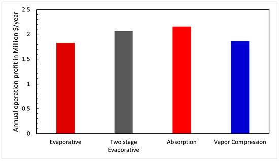
Figure 21.
Annual added profit.
Ahmadzadehtalatapeh and Rashidi [29] reported on the initial investment costs of evaporative cooling, vapor-compression and absorption inlet cooling systems. As shown, the initial investment costs per added power are USD 89, 259 and 267 per kW for evaporative, water-cooled absorption and water-cooled vapor-compression inlet cooling systems, respectively. For hybrid absorption and vapor-compression systems, investment costs should include both evaporative and refrigeration cooling equipment costs. The initial investment cost was estimated from
where Ci is USD per added kW, Cev and Cr are initial investment costs per added kilowatt for evaporative and refrigeration systems, respectively, and Re is the ratio between the maximum sensible evaporative cooling to total maximum cooling:
For the two-stage evaporative inlet cooling system, investment costs should include both direct and indirect evaporative cooling equipment costs. The initial investment costs of the two-stage evaporative inlet cooling system will be far less than those of absorption and vapor-compression chillers and in the cost range of the direct evaporative inlet cooling system. In this analysis, it was assumed that the costs of direct and indirect evaporative cooling are similar. Consequently, the total investment cost (USD) of inlet cooling systems was estimated from
where Padd is the maximum monthly added power owed to inlet cooling. The payback period (PBP) was estimated from
Table 3 lists the investment capital cost, annual added profit and payback period. The payback period falls between 0.5 and 1.1 years. The PBP for evaporative and two-stage evaporative systems is ~50% of the hybrid refrigeration inlet cooling systems. The data in Table 3 show the good feasibility of investment in inlet cooling systems. However, for hot, dry regions such as the city of Riyadh, evaporative and two-stage evaporative inlet cooling systems compete strongly with hybrid refrigeration inlet cooling systems.
Table 3.
Initial cost and payback period.
6. Conclusions
Evaporative, two-stage evaporative, absorption refrigeration evaporative and vapor-compression refrigeration evaporative TIAC systems were investigated for GE 7001EA gas turbine model under the weather conditions of the city of Riyadh. Thermoflex software was used to simulate the performance of the GE 7001EA gas turbine using different TIAC systems. This investigation was conducted to examine the feasibility of the two-stage evaporative TIAC system in hot dry regions. This system can cool the inlet air below the wet-bulb temperature. The simulation data indicate the competitive performance of the gas turbine incorporated with the two-stage evaporative TIAC system, where the power output in summer months increases by 20% compared with turbines without TIAC systems. However, using evaporative, hybrid absorption and hybrid vapor-compression TIAC systems increases the power output in summer months by 16.8, 19.3 and 19.3%, respectively. Regarding water consumption, the hybrid absorption system consumes 80%, 130% and 240% more water than the hybrid vapor-compression, the two-stage evaporative and the evaporative TIAC systems, respectively. The added annual profit of using the two-stage evaporative TIAC system is 10% higher than evaporative TIAC, 7% higher than the hybrid vapor-compression TIAC and 4% lower than the hybrid absorption TIAC systems. The payback period of the two-stage evaporative TIAC system is 42% and 50% less than the than the hybrid vapor-compression and the hybrid absorption TIAC systems, respectively.
Funding
This work was supported by King Saud University, Deanship of Scientific Research and Research Center College of Engineering.
Institutional Review Board Statement
Not Applicable.
Informed Consent Statement
Not Applicable.
Data Availability Statement
Not Applicable.
Acknowledgments
The author thanks the Deanship of Scientific Research and RSSU at King Saud University and Research Center College of Engineering for their technical support.
Conflicts of Interest
The author declares no conflict of interest.
Nomenclature
| AAP | added annual profit, $/year |
| Ca | added annual fuel and water costs, $/year |
| Ccap | total investment cost ($) of inlet cooling system |
| Cev | investment cost of evaporative TIAC system per added kW power, $/kW |
| Cev | investment cost of refrigeration TIAC system per added kW power, $/kW |
| Eic | annual energy generated with TIAC system, MWh/year |
| Ewic | annual energy generated without TIAC system, MWh/year |
| HR | Heat rate, kJ/kWh |
| LHV | low heating value of used natural gas, 44,472 kJ/kg |
| mf,ic | annual fuel consumption with TIAC system, ton/year |
| mf,wi | annual fuel consumption without TIAC system, ton/year |
| mw | total water consumption, m3/year |
| P | Power, kW |
| Padd | maximum monthly added power, kW |
| PBP | payback period, year |
| Pf | price of natural gas fuel, $/million Btu |
| Pw | water price (Pw = 1.6 $/m3) |
| Qe | sensible cooling load of evaporative TIAC |
| Qr | sensible cooling load of refrigeration TIAC |
| Sa | added annual sale value of added energy, $/year |
| Re | the ratio between evaporative cooling to total cooling |
| Tae | current tariff of electricity in Saudi Arabia, 0.048 $/kWh |
| TIAC | turbine inlet air cooling |
| ηic | efficiency with TIAC system |
| ηwic | efficiency without TIAC system |
References
- Zeitoun, O.; Al-Ansary, H.; Nuhait, A. Gas Turbine Power Generator with Two-Stage Inlet Air Cooling, US 2016; 0230660 A1. Available online: https://www.patentguru.com/US2016230660A1 (accessed on 2 March 2021).
- Al-Ansary, H.A.; Orfi, J.A.; Ali, M.E. Impact of the use of a hybrid turbine inlet air cooling system in arid climates. Energy Convers. Manag. 2013, 75, 214–223. [Google Scholar] [CrossRef]
- Ali, M.; Zeitoun, O.; Al-Ansary, H.H.; Nuhait, A. Numerical simulation of GE 7001 EA gas turbine using experimental data for compressor inlet air cooling. In Proceedings of the 10th International Conference on Heat Transfer, Fluid Mechanics and Thermodynamics, Orlando, FL, USA, 14–16 July 2014. [Google Scholar]
- Zeitoun, O.; Ali, M.; Al-Ansary, H.; Nuhait, A. Ceramic tubes membrane technology as a new humidification technique for Gas Turbine Inlet Air Cooling. Int. J. Therm. Sci. 2014, 80, 1–10. [Google Scholar] [CrossRef]
- Gas Turbine & Heat Recovery Cycles Flexibility. In GE Publication; Report No. 07233; General Electric Company: Boston, MA, USA, 1997.
- Al-Ibrahim, A.M.; Varnham, A. A Review of inlet air-cooling technologies for enhancing the performance of combustion turbines in Saudi Arabia. Appl. Therm. Eng. 2010, 30, 1879–1888. [Google Scholar] [CrossRef]
- Deng, C.; Al-Sammarraie, A.T.; Ibrahim, T.K.; Kosari, E.; Basrawi, F.; Ismail, F.B.; Abdalla, A.N. Air Cooling Techniques and Corresponding Impacts on Combined Cycle Power Plant (CCPP) Performance: A Review. Int. J. Refrig. 2020, 120, 161–177. [Google Scholar] [CrossRef]
- Alhazmy, M.M.; Najjar, Y.S.H. Augmentation of Gas Turbine Performance Using Air Coolers. Appl. Therm. Eng. 2004, 24, 415–429. [Google Scholar] [CrossRef]
- Wang, T.; Braquet, L. Assessment of Inlet Cooling to Enhance Output of a Fleet of Gas Turbines. In Proceedings of the IETC 30th Industrial Energy Technology Conference, New Orleans, LA, USA, 6–9 May 2008. [Google Scholar]
- Ehyaei, M.A.A.; Mozafari b, M.H. Alibiglou, Exergy, Economic & Environmental (3E) Analysis of Inlet Fogging for Gas Turbine Power Plant. Energy 2011, 36, 6851–6861. [Google Scholar]
- Mahto, D.; Pal, S. Thermodynamics and Thermo-Economic Analysis of Simple Combined Cycle with Inlet Fogging. Appl. Therm. Eng. 2013, 51, 413–424. [Google Scholar] [CrossRef]
- Carmona, J. Gas Turbine Evaporative Cooling Evaluation for Lagos e Nigeria. Appl. Therm. Eng. 2015, 89, 262–269. [Google Scholar] [CrossRef]
- Ehyaei, M.A.; Tahani, M.; Ahmadi, P.; Esfandiari, M. Optimization of Fog Inlet Air Cooling System for Combined Cycle Power Plants Using Genetic Algorithm. Appl. Therm. Eng. 2015, 76, 449–461. [Google Scholar] [CrossRef]
- Saghafifar, M.; Gadalla, M. Innovative Inlet Air Cooling Technology for Gas Turbine Power Plants Using Integrated Solid Desiccant and Maisotsenko Cooler. Energy 2015, 87, 663–677. [Google Scholar] [CrossRef]
- Erickson, D.C.; Kyung, I.; Anand, G.; Makar, E.E. Aqua Absorption Turbine Inlet Cooler. In Proceedings of the ASME International Mechanical Engineering Congress & Exposition, Washington, DC, USA, 16–21 November 2003. [Google Scholar]
- Fernández-Seara, J.; Vales, A.; Vázquez, M. Heat Recovery System to Power an Onboard NH3−H2O Absorption Refrigeration Plant in Trawler Chiller Fishing Vessels. Appl. Therm. Eng. 1998, 18, 1189–1205. [Google Scholar] [CrossRef]
- Vanderlinden, J. Heat Recovery from Flue Gases with Absorption Cooling. Belg. Natl. Team Waste H.E.A.T. Recov. Newsl. 1999, 1, 22–23. [Google Scholar]
- Ondryas, I.S.; Wilson, D.A.; Kawamoto, M.; HAUB, G.L. Options in Gas Turbine Power Augmentation Using Inlet Air Chilling, Congress and Exposition. In Proceedings of the ASME 1990 International Gas Turbine and Aeroengine Congress and Exposition, Brussels, Belgium, 11–14 June 1990. [Google Scholar]
- Alhazmy, M.M.; Jassim, R.K.; Zaki, G.M. Performance Enhancement of Gas Turbines by Inlet Air-Cooling in Hot and Humid Climates. Int. J. Energy Res. 2006, 30, 777–797. [Google Scholar] [CrossRef]
- Marzouk, A.; Hanafi, A. Thermo-Economic Analysis of Inlet Air Cooling in Gas Turbine Plants. J. Power Technol. 2013, 93, 90–99. [Google Scholar]
- Kodituwakku, D.R. Effect of Cooling Charge Air on the Gas Turbine Performance and Feasibility of Using Absorption Refrigeration in the “Kelanitissa” Power Station, Sri Lanka. Master’s Thesis, KTH School of Industrial Engineering and Management, Stockholm, Sweden, 2014. [Google Scholar]
- Mohapatra, A.K. Sanjay Comparative Analysis of Inlet Air Cooling Techniques Integrated to Cooled Gas Turbine Plant. J. Energy Inst. 2015, 88, 344–358. [Google Scholar] [CrossRef]
- Barakat, S.; Ramzy, A.; Hamed, A.M.; El Emam, S.H. Enhancement of Gas Turbine Power Output Using Earth to Air Heat Exchanger (EAHE) Cooling System. Energy Convers. Manag. 2016, 111, 137–146. [Google Scholar] [CrossRef]
- El-Shazly, A.A.; Elhelw, M.; Sorour, M.M.; El-Maghlany, W.M. Gas turbine performance enhancement via utilizing different integrated turbine inlet cooling techniques. Alex. Eng. J. 2016, 55, 1903–1914. [Google Scholar] [CrossRef]
- Yang, C.; Yang, Z.; Cai, R. Analytical Method for Evaluation of Gas Turbine Inlet Air Cooling in Combined Cycle Power Plant. Appl. Energy 2009, 86, 848–856. [Google Scholar] [CrossRef]
- Mohapatra, A.K. Sanjay Thermodynamic Assessment of Impact of Inlet Air Cooling Techniques on Gas Turbine and Combined Cycle Performance. Energy 2014, 68, 191–203. [Google Scholar] [CrossRef]
- Gkoutzamanis, V.; Chatziangelidou, A.; Efstathiadis, T.; Kalfas, A.; Traverso, A.; Chiu, J.N.W. Thermal Energy Storage for Gas Turbine Power Augmentation. J. Glob. Power Propuls Soc. 2019, 3, 592–608. [Google Scholar] [CrossRef]
- Beigi, B.F.; Mehdipour, R. Investigation of Cold Storage Performance to Improve Management of Power Generation in Thermal Power Plants in Iran. Energy 2020, 213, 118843. [Google Scholar] [CrossRef]
- Ahmadzadehtalatapeh, M.; Rashidi, H.R. Performance Enhancement of Gas Turbine Units by Retrofitting with Inlet Air Cooling Technologies (IACTs): An Hour-by-Hour Simulation Study. J. Braz. Soc. Mech. Sci. Eng. 2020, 42, 139. [Google Scholar] [CrossRef]
- Dizaji, H.S.; Hu, E.J.; Chen, L.; Pourhedayat, S. Using Novel Integrated Maisotsenko Cooler and Absorption Chiller for Cooling of Gas Turbine Inlet Air. Energy Convers. Manag. 2019, 195, 1067–1078. [Google Scholar] [CrossRef]
- Climate Charts, Riyadh, Saudi Arabia. Available online: https://www.climate-charts.com/Locations/s/SD40438.html (accessed on 2 March 2021).
- Consumption Tariffs. Available online: https://www.se.com.sa/en-us/customers/Pages/TariffRates.aspx (accessed on 2 March 2021).
- Natural Gas Monthly Price. Available online: https://www.indexmundi.com/commodities/?commodity=natural-gas&months=360 & Currency=sar (accessed on 2 March 2021).
- Saudi Arabia Raises Business Water Tariff. Available online: https://www.pinsentmasons.com/out-law/news/saudi-arabia-raises-business-water-tariff-by-50 (accessed on 2 March 2021).


Publisher’s Note: MDPI stays neutral with regard to jurisdictional claims in published maps and institutional affiliations. |
© 2021 by the author. Licensee MDPI, Basel, Switzerland. This article is an open access article distributed under the terms and conditions of the Creative Commons Attribution (CC BY) license (http://creativecommons.org/licenses/by/4.0/).