Article

Development of Flexible Triboelectric Generators Based on Patterned Conductive Textile and PDMS Layers

1
Department of Biomedical Engineering, National Cheng Kung University, No. 1, University Road, Tainan City 701401, Taiwan
2
Department of Mechanical Engineering, National Chung Cheng University, No. 168, Sec. 1, University Road, Chiayi 621301, Taiwan
3
Department of Mechatronic Engineering, National Taiwan Normal University, No. 162, Sec. 1, Ho-Ping E. Road, Taipei 106308, Taiwan
4
Department of Mechanical Engineering, National Taipei University of Technology, No. 1, Sec. 3, Zhongxiao E. Road, Taipei 106344, Taiwan
*
Authors to whom correspondence should be addressed.
Energies 2021, 14(5), 1391; https://doi.org/10.3390/en14051391
Submission received: 16 February 2021 / Revised: 27 February 2021 / Accepted: 28 February 2021 / Published: 3 March 2021
(This article belongs to the Section D1: Advanced Energy Materials)

Abstract

:
A triboelectric generator (TEG) is a simple coupling combined with triboelectrification and electrostatic induction, which can convert mechanical energy into electrical energy and have the potential for self-powered device application. In this study, TEGs are fabricated consisting of a conductive textile (CT) layer (a fabric woven with polyester and stainless steel) and a polydimethylsiloxane (PDMS) layer. The CT friction layer is also used as a conductive electrode and designed with various surface morphologies, including unpatterned, dots, and lines with 1 and 2 cm spacings. Experimental results show that the TEG with an unpatterned CT layer produces an output voltage of 54.6 V and an output current of 5.46 µA. The patterned surfaces increase the effective contact area and friction effect between the CT and PDMS layers and hence enhance the output voltage and current to 94.4 V and 9.44 µA. Compared to the unpatterned CT layer, the pattern use of 1 cm spaced lines, 2 cm spaced lines, and dots improves the output voltage and current by 1.73, 1.68, and 1.24 times, respectively. Moreover, the TEG with 1 cm spaced lines generates a high output power density of 181.9 mW/m2.

Graphical Abstract

1. Introduction

Conventional mechanisms for converting electromagnetic induction into electric power harvest only high-frequency mechanical energy [1,2]. However, many natural sources of mechanical energy in the environment operate at low frequencies, e.g., wind, raindrops, ocean waves, and human body motion [3,4,5,6,7]. Consequently, the issues of developing triboelectric generators (TEGs) or triboelectric nanogenerators (TENGs) to harvest these low-frequency energies have attracted significant attention in the literature. TEGs have been developed for many applications, such as self-powered wearable electronics, Internet of Things (IoT) devices, electronic skins, energy storage devices, potential diagnostics, biosensors, and body motion sensors [8,9,10,11,12,13,14,15,16,17]. The electric power produced by such TEG/TENG devices may be generated by many different mechanical energy conversion mechanisms, including rolling, bending, pressing, rotating, roll–swing, vibration, and sliding [18,19,20,21,22,23,24,25]. However, irrespective of the mechanism employed, all TEGs/TENGs rely on a contact electrification and electrostatic induction effect, in which the materials within the TEGs/TENGs become electrically charged once they are brought into contact with one another and subsequently separated [26,27,28,29,30,31,32]. TEG/TENG devices are made of two different materials (mostly polymers) as friction (contact) layers and sliding layers, respectively, where these materials are deliberately chosen to have different polarities (i.e., positive and negative charges). However, the performance of TEGs/TENGs is fundamentally dependent not only on the choice of materials, but also on the surface morphologies of the contact interface between the two layers when they are pressed into contact with one another.
TEGs/TENGs have many advantages as energy-harvesting devices, including a low production cost, easy moldability, good flexibility, high reliability, high efficiency, and environmental friendliness. As a result, they represent a promising alternative to traditional batteries for wearable devices, which need frequent recharging and regular replacement. The literature contains many proposals for TEGs/TENGs fabricated using various materials as the friction layer. For example, Chung and Ke [33] utilized a CO2 laser to fabricate a master mold patterned with a microneedle array on a polymethyl methacrylate (PMMA) substrate. The mold was then used to cast the microneedle array on a polydimethylsiloxane (PDMS) substrate as the friction layer. The TENG device was completed using PDMS as the lower friction layer and aluminum (Al) foil as the upper contact layer and the electrode material. The open-circuit voltage (Voc) and short-circuit current (Isc) of the proposed TENG device were shown to be 123 V and 109.7 μA, respectively. Kim and Seo [34] fabricated a TENG consisting of a galinstan alloy electrode patterned on a PDMS substrate as the lower layer and a copper electrode as the upper layer. The TENG device showed a Voc of approximately 75 V at a tapping frequency of 4 Hz and an Isc of 1.38 μA. Jeon et al. [35] patterned a zinc oxide (ZnO) nanostructure on a polyethylene naphthalate (PEN) substrate coated with indium tin oxide (ITO) as the active layer of a TENG and used a polyimide (PI) film adhered to an Al electrode surface as the negative friction layer. The experimental results showed that the Voc and Isc were 22.4 V and 5.43 μA, respectively. Hwang et al. [36] presented a metal-free TENG incorporating a multi-walled carbon nanotube (MWCNT) mesh deposited on a PDMS layer. The Voc of the TENG increased from 85 to 250 V as the finger pressure applied to the PDMS layer increased from 230 to 670 Pa. Moreover, the average power density of the device was 27 W/m2 at 10 MΩ matched impedance.
In addition, many TENGs with various conductive textiles as the friction layer had been reported to investigate their features for wearable devices. For example, Paosangthong et al. [37] fabricated a textile-based triboelectric nanogenerator with an alternating positive and negative freestanding grating structure (pnG-TENG). When the designed pnG-TENG was 10 gratings of nylon fabric and PVC heat transfer vinyl, the measured root mean square (RMS) Voc, Isc, and power density were 136 V, 2.68 μA, and 38.8 mW/m2, respectively. Dong et al. [38] developed CT-based TENGs with silver conductive yarns wrapped with polytetrafluoroethylene and nylon66. A peak power density of 1.48 and 7.531 mW/m2 was achieved during the stretching and compression motions, respectively. The CT-based TENGs were displayed to be tender and comfortable. Chu et al. [39] exhibited ultrathin TENGs with <1.5 μm polydimethylsiloxane, < 1 nm graphene, and <0.9 μm polyethylene terephthalate as the triboelectric layer, electrode, and substrate, respectively. The TENGs with a single-electrode-based structure generated electricity by contact with various clothes (nylon, silk, cotton, latex) or the human body, and they showed a maximum Voc, Isc, and power density of 47.1 V, 7 μA, and 144 mW/m2, respectively.
Although the TEGs/TENGs with conductive textiles used as the friction layer are easily realized wearable electronics and self-powered devices, the CT-based TENGs with nano-scale structures have only generated low power densities at present. We believe that further improvement in power generation could be achieved via use of appropriate device geometries and materials. Hence, this study aims to develop a TEG based on a conductive textile as the active layer and PDMS coated on a thin Al foil as the negative friction layer to generate a large power density. The conductive textile layer is designed with various surface morphologies, including unpatterned, dots, and parallel lines, in order to increase the effective contact area and friction effect between the upper and lower layers. The performance of the various TEGs is evaluated using a self-built testing platform consisting of a pneumatic cylinder and a flat plate designed to generate a reciprocating compression force on the active layer of the device. As a result, the TEG with 1 cm spaced lines generates a high output power density of 640 mW/m2.

2. Experimental Procedures

2.1. Selection of Friction Materials

TEGs are based on the principle of contact electrification, in which a reciprocating vertical contact and separation motion of two materials with different polarities (i.e., positive and negative) is exploited to produce an electrostatic charge. The TEG developed in the present study was fabricated using a commercial conductive textile (CT), PDMS, and Al foil. The CT (AFC® M02, Asiatic Fiber Corporation, Taoyuan City, Taiwan) consists of woven conductive yarn spun from 20% stainless steel fiber and 80% polyester filament and has a sheet resistance of approximately 104 Ω/sq. Under electrostatic induction, the CT has a tendency to lose electrons and become positively charged, while the PDMS friction layer acquires electrons and becomes negatively charged. Notably, both materials are cost-effective, durable, and soft. As a result, they are ideally suited to the fabrication of flexible generators. Moreover, the CT is breathable and can therefore be worn comfortably against the human skin. Finally, the CT has high electrical conductivity and retains all of its favorable characteristics even after washing.

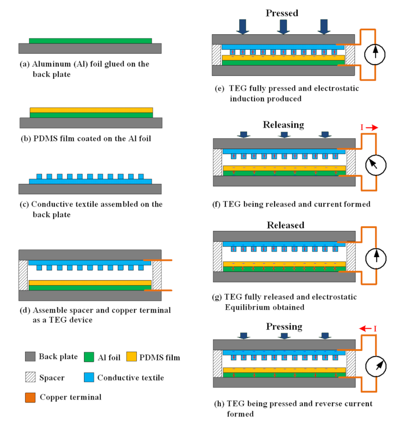
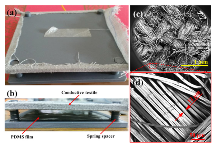
2.2. TEG Fabrication and Working Principles

Figure 1 presents a schematic diagram of the proposed TEG structure, its fabrication process, and the triboelectric principle upon which it operates. In fabricating the TEG, a thin Al foil with an average thickness of 15 μm and dimensions of 7 × 7 cm was first glued to a 1-cm-thick polyvinyl chloride (PVC) backplate to serve as the back electrode (Figure 1a) and a PDMS film was then coated on this foil as a sliding layer (Figure 1b). The PDMS precursor solution was prepared by mixing silicone elastomer and a cross-linker (Sylgard 184, Dow Corning) in a mass ratio of 10:1. The mixture was degassed in a vacuum chamber for approximately 60 min in order to remove any air bubbles trapped within the mixture and was subsequently poured on the Al foil. The elastomer mixture was then spin-coated on the Al foil at 1000 rpm for 10 s to create a film. The film was cured on a hot plate at 85 °C for 45 min and was then allowed to cool naturally to room temperature to form a PDMS layer with a thickness of about 500 μm. The CT was glued to a PVC backplate with dimensions of 9 × 9 cm to serve as both the upper friction layer and the top electrode (Figure 1c). To increase the contact area between the CT and PDMS layers, thereby improving the output voltage, a hand-stitch embroidery technique was used to create protruding arrays with dot and line patterns on the CT surface. The embroidery thread was fabricated from the same material as the textile and the protruding patterns had an average height of approximately 1.4 mm in every case. The TEG device was assembled by placing four spring spacers and guide rods between the upper CT layer and lower PDMS layer and connecting copper wires to the two layers to form electrical terminals (Figure 1d).
Figure 1e–h show the power generation principle during the TEG operation. Initially, the CT layer and PDMS layer are pushed into contact with one another under the application of an external force (Figure 1e). As a result, an electrostatic charge is formed at the contact interface with a balanced distribution of positive and negative charges on the CT and PDMS surfaces, respectively. Since the interface is in a condition of electrostatic equilibrium, no electron flow is created in the external circuit. However, when the CT layer is released, the positive and negative charges are separated. The resulting triboelectric charges are no longer compensated, and hence dipoles are formed at the interface between the PDMS film and Al foil. As a result, the foil and CT layer accumulate negative and positive charges, respectively. The resulting difference in the electric potential between them drives a flow of electrons through the external load, as shown in Figure 1f. In the fully released condition, the electrostatic charges are once again balanced between the CT and PDMS electrodes. Consequently, the electric potential within the system is in equilibrium, and no external electric current is produced (Figure 1g). When the external force is re-applied to the upper CF layer, the gap between the CT and PDMS electrodes reduces. As a result, the triboelectric charges cannot be compensated, and hence an electric potential difference is produced between the two layers, which drives an electron flow through the external load in a direction opposite to that when the CF layer is released (Figure 1h). Finally, when the CT layer and Al foil are in full contact once again, an electrostatic equilibrium condition is re-established, and hence no external electric current is produced (Figure 1e). By applying a reciprocating force to the upper CF layer, an alternating flow of electrons is driven through the external load (Figure 1e–h), resulting in the production of a continuous electric signal with a form similar to that of a sinusoidal wave.

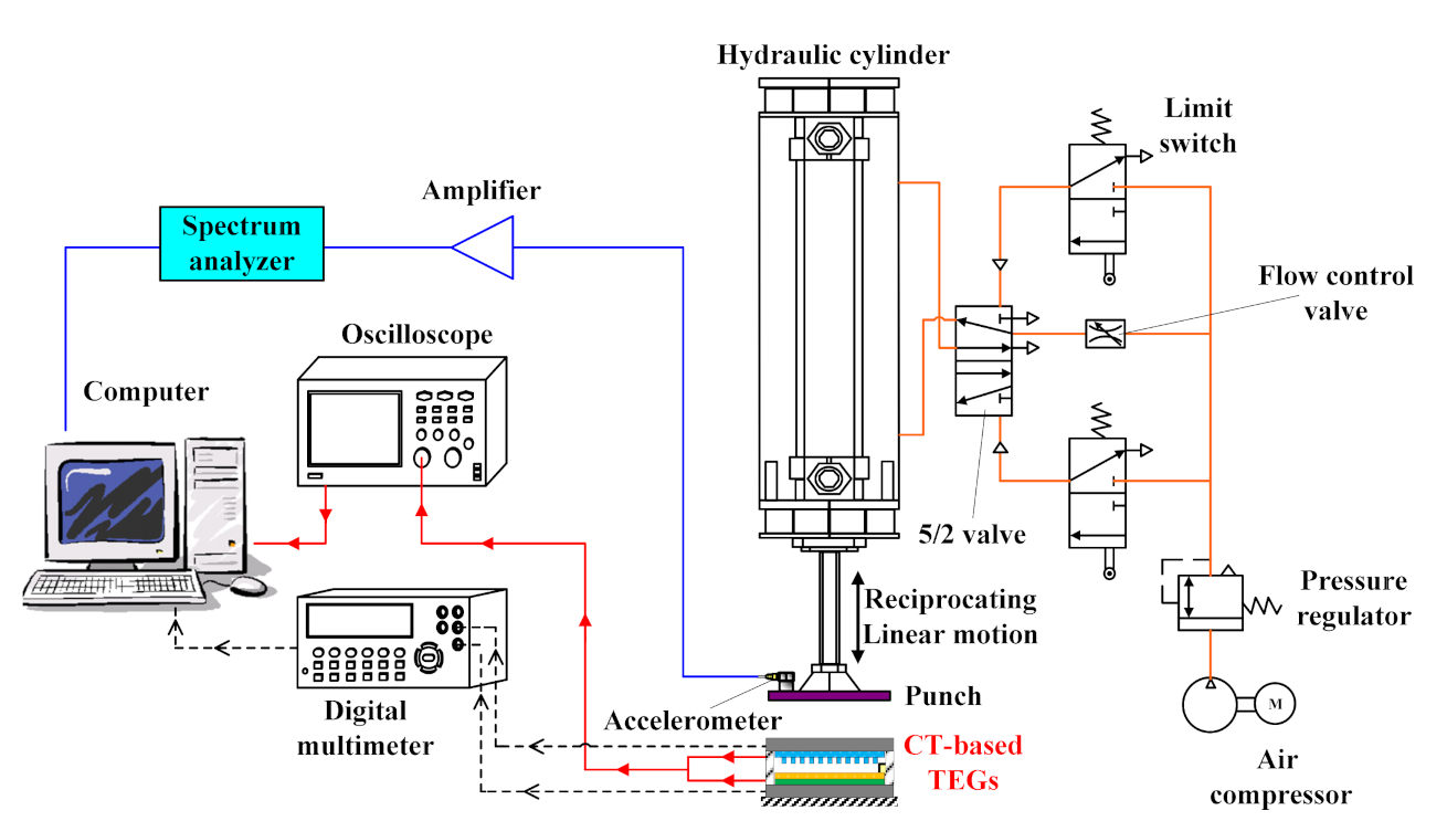
2.3. TEG Performance Measurement

The performance of the TEGs with different CT surface patterns was evaluated using a self-built testing platform consisting of a pneumatic cylinder and a flat contact plate with a reciprocating linear motion, as displayed in Figure 2. Compressed air from a pressure regulator and a flow control valve were used to control the force and frequency of the punch at the end of the pneumatic cylinder. Moreover, a limit switch connected with a five- or two-way pneumatic valve could be used to control the reciprocating linear motion of the pneumatic cylinder. The tests were performed using a reciprocating compression action with a frequency in the range of 1–5 Hz. The applied frequency of the punch was measured using a spectrum analyzer combined with an accelerometer and amplifier. The values of the output V and the output current I for each TEG were measured using a GDM-8245 digital multimeter and a GDS-1072B digital oscilloscope (Good Will Instrument Co., Ltd., Taipei, Taiwan). In addition, the fiber weave of the CT was observed using a field-emission scanning electron microscope (FE-SEM) (S4800, Hitachi, Japan). Finally, the sheet resistance and electrical conductivity of the CT were measured using a four-point probe resistance meter (5601Y, Chitai Electronic, Taiwan).

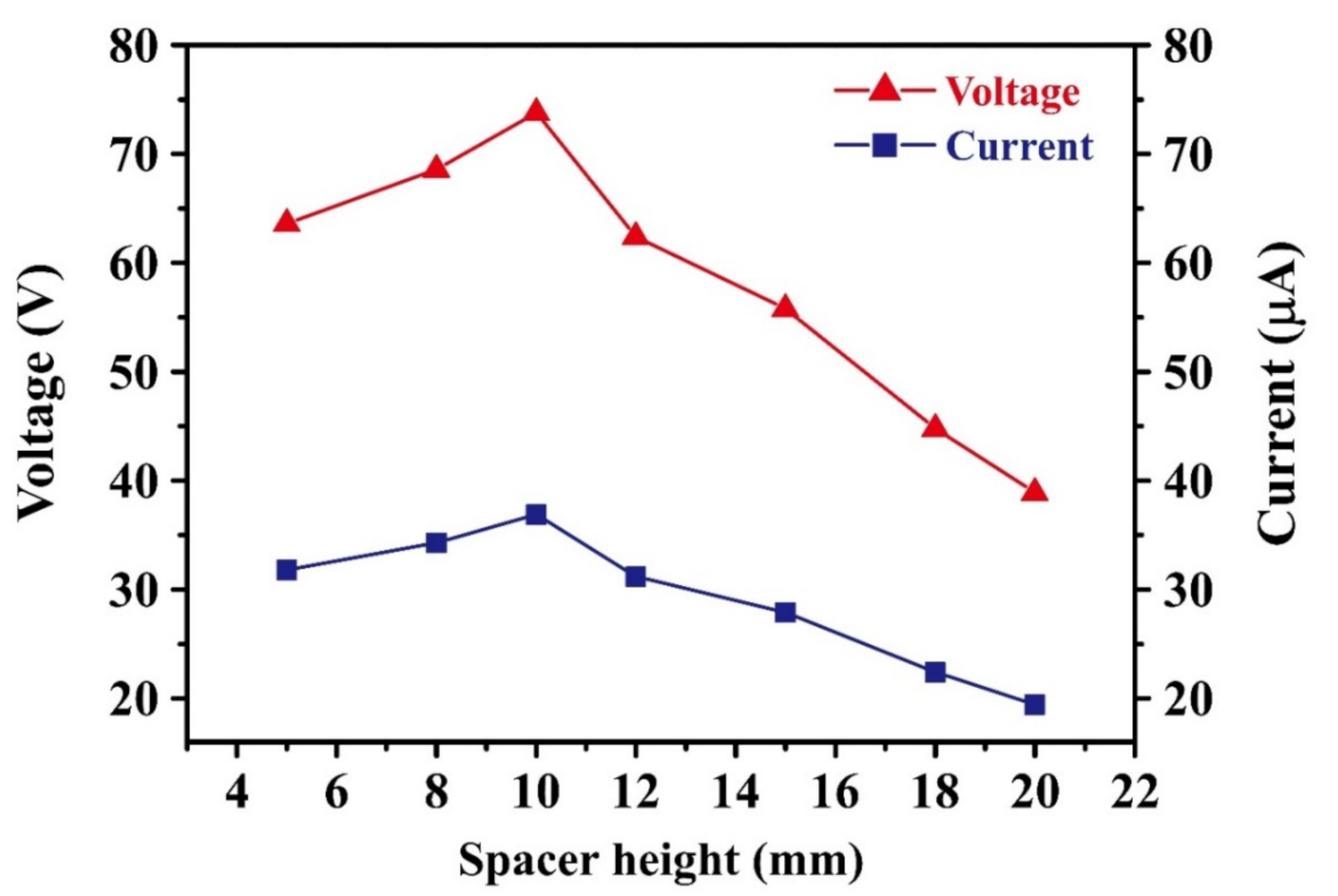
3. Results and Discussion

Figure 3 presents (a) top-view and (b) side-view photographs of the assembled CT-based TEG device, and SEM images of (c) the woven stainless steel/polyester fiber in the conductive textile and (d) the close-up view of the fiber. As shown in Figure 3a, the CT consists of a uniform weave of stainless steel (20%) and polyester (80%) fibers with an average diameter of around 12 µm. Its surface resistivity was found to be approximately 104 Ω/sq. As described in Section 2.2, the CT served as both a friction layer and an electrode. Moreover, the protruding patterns embroidered on the textile surface served to enhance the triboelectrification effect by increasing the effective contact area and friction effect between the CT active layer and the PDMS sliding layer. As shown in Figure 3b, the CT layer and PDMS layer were separated by four springs and associated guide rods to return the CT layer to its initial position after the applied force was removed.
Figure 4 shows the variation in the output voltage and output current of the TEG device with an unpatterned CT layer as a function of the spacer height. Note that the pneumatic cylinder was operated with a frequency of 5 Hz, a stroke length of 8.5 cm, and a gas pressure of 3.5 bar for 100 s. Note also that the data presented in Figure 4 were collected using the same TEG device with the springs and guide rods simply replaced between each test. The results show that the output voltage and current both increase as the spacer height increases from 5 to 10 mm but then decrease rapidly as the spacer height is further increased to 20 mm. The spacer height indicates the height of the spring spacer, as shown in Figure 3b. For a spacer height of 10 mm, the output voltage and output current are equal to 73.8 V and 36.9 μA, respectively. According to previous studies [40,41,42], the output voltage, V, of a TEG can be approximated as
V = σ d ε 0
where σ is the triboelectric charge density on the contact surface, d is the gap between the two contact materials (equal to the spacer height), and ε0 is the vacuum permittivity. According to Equation (1), the output voltage should increase continuously with an increasing gap between the two contact materials. However, for the present TEG, the output voltage reduces significantly as the gap between the CT and PDMS layers increases beyond 10 mm. This apparent anomaly can be attributed to two main reasons: (1) for larger spacer heights (i.e., more than 10 mm), full contact between the CT and the PDMS layer is not achieved under the maximum displacement of the pneumatic cylinder; and (2) the response time of the springs reduces (i.e., becomes faster) as the spacer height increases, and hence the amount of electron transfer also reduces. Thus, the 10-mm-thick spring was used throughout this experiment.
Figure 5a,b show the output signals (voltage and current) obtained from TEG devices with loose and tight CT layers, respectively. Note that the CT layer is unpatterned in both cases and the TEGs are connected to an external load with a resistor of 10 MΩ. According Ohm’s law, the voltage and current are directly proportional when the resistance is fixed in this study. The average V and I of the TEG device with a loose CT layer are 56.2 V and 5.62 μA, respectively. By contrast, the average V and I of the device with a tight CT layer are 66.4 V and 6.64 μA, respectively. The taut CT layer results in a higher output efficiency since it leads to a more complete contact with the PDMS layer and therefore allows the electrons to move more freely through the external load.
As described in Section 1, the CT layer was patterned with three different surface morphologies, namely, dots (circles) with diameters of approximately 5 mm, parallel lines with a 2 cm spacing, and parallel lines with a 1 cm spacing. The protruding height was approximately 1.4 mm in every case and the patterns were embroidered using the same thread as that used to produce the CT (namely, stainless steel fibers and polyester filaments).
Figure 6 shows the output voltages and currents of the TEG devices with the unpatterned, dot-patterned, 2 cm spaced line-patterned, and 1 cm spaced line-patterned CT layers. Note that the CT layer was pulled tight in every case, and the operating pressure and external load resistance were equal to 3.5 bar and 10 MΩ, respectively. The results show that the output voltage and current increase approximately linearly as the CT surface morphology changes from unpatterned (54.6 V, 5.46 µA) to dot-patterned (68.0 V, 6.80 µA) to line-patterned (91.7 V, 9.17 µA for a 2 cm line spacing and 94.4 V, 9.44 µA for a 1 cm line spacing). The 1 cm spaced line pattern increases the output voltage and current by around 1.73 times compared to the unpatterned CT, 1.24 times compared to the dot pattern, and 1.68 times compared to the 2 cm spaced line pattern. A more compact line pattern increases the material deformation and friction effect at the contact interface between the CT layer and the PDMS layer and hence results in a greater electron exchange between them. Notably, even though the flat (unpatterned) CT surface has a greater contact area with the PDMS layer, the friction effect between them is reduced, and hence the electron flow through the external load is also reduced.
Figure 7 shows the output voltage and current of the best textile/PDMS assembled TEG with a 1 cm spaced line pattern for impact frequencies ranging from 1 to 5 Hz. Note that the impact stroke length and gas pressure of the pneumatic cylinder are 8.5 cm and 4 bar in every case. It is seen that the output voltage and current increase from 54.6 to 95.6 V and 5.46 to 9.56 μA, respectively, as the impact frequency is increased from 1 to 5 Hz. This finding is reasonable because as the impact frequency increases, the electric charge produced by the TEG system accumulates more rapidly, and hence a larger electrical output is produced.
For wearable electronics, washability and durability are a critical concern for improving the practicality of the device. Accordingly, the present study evaluated the performance of the TEG device with an unpatterned CT layer following repeated washing (up to nine times) in a commercial neutral detergent. The tests were performed using an impact frequency, impact stroke length, gas pressure, and testing time of 5 Hz, 8.5 cm, 3.5 bar, and 100 s, respectively. The corresponding results are presented in Figure 8a. It is seen that the output voltage and current remain stable at approximately 66.4 V and 6.64 μA, respectively, for the first seven washing cycles. The voltage and current reduce slightly to 64.8 V and 6.48 μA, respectively, after the eighth washing cycle and then reduce significantly to 63.2 V and 6.32 μA, respectively, after the ninth cycle. The capacity of contact electrification and electrostatic induction became weakened after washing seven times because the softened textile causes the friction strength to start diminishing. Meanwhile, the drop in the output signals was attributed to the slight increase in resistance of the textile after many washing cycles with detergent.
The durability of the TEG device was evaluated over a period of 3 months, as shown in Figure 8b. On each day of the three-month period, the output voltage and current were measured using an impact frequency, impact stroke length, gas pressure, and testing time of 5 Hz, 8.5 cm, 3.5 bar, and 100 s, respectively. As shown in Figure 8b, the output voltage and current remained approximately stable over the first two months, with values of 66.4 V and 6.64 μA, respectively, after four weeks and 66.1 V and 6.61 μA, respectively, after eight weeks. However, after ten weeks, the output voltage and current reduced slightly to 63.1 V and 6.31 μA, respectively, while after 12 weeks, the voltage and current reduced significantly to 54.5 V and 5.45 μA. The reduction in the output performance of the TEG device suggests that following prolonged usage, the textile fibers tend to adhere to the PDMS film, or the PDMS film starts to stick to the CT layer, thereby reducing the electron transfer between the two layers.
The charging effect of TEG devices depends on the resistivity of the external load. Accordingly, the output voltage and current of the TEG device with the 1 cm line spacing were measured for external resistance loads in the range of 1–30 MΩ. Figure 9a shows the change in the output voltage and current for the TEG as a function of the external load. As expected, the output voltage increases, while the current reduces, as the load resistance increases. In particular, the output voltage increases from 56 to 98 V as the load resistance is increased from 1 to 30 MΩ, while the output current reduces from 56 to approximately 3.27 μA. Figure 9b shows the corresponding variation in the output power of the TEG (as evaluated simply by P = IV). It is seen that the output power reduces from around 3.14 mW for an external resistance of 1 MΩ to approximately 0.32 mW for a resistance of 30 MΩ.
The power density of the TEG can be determined as W = P/A, where W is the power density, P is the output power, and A is the surface area of the contact interface. The TEG developed in the present study has a power density of up to 181.9 mW/m2 when the generated power and surface area of the contact interface were 3.14 mW and 49 cm2, respectively. Patterning the CT surface with an appropriate raised morphology (i.e., a parallel line array with a spacing distance of 1 cm, in the present case) provides an effective means of improving the power density of the TEG device.
To demonstrate the practical applicability of the TEG device, sixty commercial light-emitting diode (LED) bulbs were attached to the TEG as an external load. The specification of these LED bulbs is a wavelength of 520–530 nm, a typical operation voltage of 3.0 V under a 20 mA driving current, and luminance of 400–800 mcd for a rated current of 20 mA. As discussed in Section 2.2, the application of an alternating pressure to the upper layer of the TEG device results in the production of a continuous electric signal with a sinusoidal-type waveform. The direction of the electrons flowing through the external load alternates between the forward and reverse directions as the upper CT layer is actuated (see Figure 4e–h). Consequently, the alternating current (AC) produced by the TEG device was converted into a direct current (DC) using a full-wave bridge rectifier circuit in order to improve the charging effect (Figure 10a). The AC current was then passed through a capacitor to light the LEDs (Figure 10b). The TEG was found to be capable of producing an output voltage of 8 V after 45 s when using a 47 μF capacitor. The resulting power was sufficient to light all 60 LED bulbs, as shown in Figure 10c. A further feasibility test was performed, in which two rechargeable batteries were charged from 1 to 2.2 V in about 1 h. The feasibility of the proposed device for either direct power purposes or charging purposes is confirmed.
Table 1 shows comparative research of critical conditions such as material combinations, the contact area of the frictional surface, and the power density or charge density for the outstanding research works conducted on textile-based triboelectric generators. Most TEGs reported in the literature have low power densities of approximately 3.3–177.8 mW/m2 [37,38,39,40,43,44,45,46,47]. Compared with this previous research, we developed triboelectric generators consisting of a woven stainless steel/polyester fiber in the conductive textile and PDMS layers through the structural modulation of the patterned conductive textile, and the frictional effects between the two materials could be improved substantially. In this study, the triboelectric generator had a high power density of 181.9 mW/m2. Moreover, the high-performance and flexible triboelectric generator can be widely applied to self-powered wearable, sporting, and energy storage devices in the future.

4. Conclusions

This study fabricated triboelectric generators (TEGs) consisting of a conductive textile (CT) as the upper friction layer and PDMS as the lower friction layer. The TEGs were designed with four different morphologies of the CT surface, namely, unpatterned, dot-patterned, line-patterned with a spacing of 1 cm, and line-patterned with a spacing of 2 cm. It has been shown that the TEG with an unpatterned CT surface generates an output voltage of 66.4 V and a current of 6.64 µA. The output voltage and current both increase when the CT surface is patterned with protruding features (e.g., dots or parallel lines) as a result of the increased effective contact area and friction force between the CT and PDMS layers. Compared to the unpatterned CT surface, the output voltage and current increase by 1.73, 1.68, and 1.24 times when the surface is patterned with 1 cm spacing parallel lines, 2 cm spacing parallel lines, and dots, respectively. It has been shown that the TEG incorporating a CT layer with 1 cm spacing parallel lines is capable of illuminating 60 LED light bulbs within 45 s and charging a battery within 1 h. Moreover, the device has good washability (up to seven times) and good durability (up to 8 weeks). Overall, the results show that the TEG has good potential for the realization of lightweight, facile-processed, cost-effective, and scalable self-powered devices.

Author Contributions

Conceptualization: Y.-R.J., C.-R.Y.; experimentation: A.E.M., C.-T.K.; validation: Y.-R.J., C.-R.Y.; investigation: S.-F.T., C.-R.Y.; resources: Y.-R.J., C.-R.Y.; writing (original draft preparation): S.-F.T., C.-R.Y.; writing (review and editing): S.-F.T., C.-R.Y. All authors have read and agreed to the published version of the manuscript.

Funding

The authors gratefully acknowledge the financial support provided to this study by the Ministry of Science and Technology of Taiwan (MOST 107-2923-M-006-003-MY3, MOST 108-2119-M-006-010, MOST109-2124-E-006-003, 108-2221-E-006-228-MY3 and 107-2923-M-006-003-MY3), AC2T research GmbH of Austria (COMET InTribology, FFG-No. 872176), and AFOSR under contract No. FA4869-06-1-0056 AOARD 064053.

Institutional Review Board Statement

Not applicable.

Informed Consent Statement

Not applicable.

Data Availability Statement

Not applicable.

Acknowledgments

The authors gratefully acknowledge the financial support provided to this study by the Ministry of Science and Technology of Taiwan under Grant Nos. MOST 107-2923-M-006-003-MY3, MOST 108-2119-M-006-010, MOST109-2124-E-006-003, 108-2221-E-006-228-MY3 and 107-2923-M-006-003-MY3. The authors would also like to acknowledge AC2T Research of Austria under COMET K2 Tribology Intelligence, and Medical Device Innovation Center (MDIC) and Intelligent Manufacturing Research Center (iMRC), National Cheng Kung University (NCKU). The research was supported in part by Higher Education Sprout Project, Ministry of Education to the Headquarters of University Advancement at National Cheng Kung University (NCKU).

Conflicts of Interest

The authors declare no conflict of interest.

References

  1. Beeby, S.P.; Torah, R.N.; Tudor, M.J.; Glynne-Jones, P.; O’Donnell, T.; Saha, C.R.; Roy, S. A micro electromagnetic generator for vibration energy harvesting. J. Micromech. Microeng. 2007, 17, 1257–1265. [Google Scholar] [CrossRef]
  2. Zhang, C.; Tang, W.; Han, C.; Fan, F.; Wang, Z.L. Theoretical Comparison, Equivalent Transformation, and Conjunction Operations of Electromagnetic Induction Generator and Triboelectric Nanogenerator for Harvesting Mechanical Energy. Adv. Mater. 2014, 26, 3580–3591. [Google Scholar] [CrossRef]
  3. Xie, Y.; Wang, S.; Lin, L.; Jing, Q.; Lin, Z.-H.; Niu, S.; Wu, Z.; Wang, Z.L. Rotary Triboelectric Nanogenerator Based on a Hybridized Mechanism for Harvesting Wind Energy. ACS Nano 2013, 7, 7119–7125. [Google Scholar] [CrossRef]
  4. Yoo, D.; Park, S.-C.; Lee, S.; Sim, J.-Y.; Song, I.; Choi, D.; Lim, H.; Kim, D.S. Biomimetic anti-reflective triboelectric nanogenerator for concurrent harvesting of solar and raindrop energies. Nano Energy 2019, 57, 424–431. [Google Scholar] [CrossRef]
  5. Wang, S.; Mu, X.; Wang, X.; Gu, A.Y.; Wang, Z.L.; Yang, Y. Elasto-Aerodynamics-Driven Triboelectric Nanogenerator for Scavenging Air-Flow Energy. ACS Nano 2015, 9, 9554–9563. [Google Scholar] [CrossRef] [PubMed]
  6. Xia, K.; Zhu, Z.; Zhang, H.; Du, C.; Fu, J.; Xu, Z. Milk-based triboelectric nanogenerator on paper for harvesting energy from human body motion. Nano Energy 2019, 56, 400–410. [Google Scholar] [CrossRef]
  7. Tao, K.; Yi, H.; Yang, Y.; Chang, H.; Wu, J.; Tang, L.; Yang, Z.; Wang, N.; Hu, L.; Fu, Y.; et al. Origami-inspired electret-based triboelectric generator for biomechanical and ocean wave energy harvesting. Nano Energy 2020, 67, 104197. [Google Scholar] [CrossRef]
  8. Xie, L.; Chen, X.; Wen, Z.; Yang, Y.; Shi, J.; Chen, C.; Peng, M.; Liu, Y.; Sun, X. Spiral Steel Wire Based Fiber-Shaped Stretchable and Tailorable Triboelectric Nanogenerator for Wearable Power Source and Active Gesture Sensor. Nano Micro Lett. 2019, 11, 39. [Google Scholar] [CrossRef] [Green Version]
  9. Miao, P.; Wang, J.; Zhang, C.; Sun, M.; Cheng, S.; Liu, H. Graphene Nanostructure-Based Tactile Sensors for Electronic Skin Applications. Nano Micro Lett. 2019, 11, 71. [Google Scholar] [CrossRef] [Green Version]
  10. Zhao, K.; Wang, Y.; Han, L.; Wang, Y.; Luo, X.; Zhang, Z.; Yang, Y. Nanogenerator-Based Self-Charging Energy Storage Devices. Nano Micro Lett. 2019, 11, 19. [Google Scholar] [CrossRef] [Green Version]
  11. Fu, Y.; He, H.; Zhao, T.; Dai, Y.; Han, W.; Ma, J.; Xing, L.; Zhang, Y.; Xue, X. A Self-Powered Breath Analyzer Based on PANI/PVDF Piezo-Gas-Sensing Arrays for Potential Diagnostics Application. Nano Micro Lett. 2018, 10, 1–12. [Google Scholar] [CrossRef] [PubMed] [Green Version]
  12. Zhang, H.; Yang, Y.; Hou, T.-C.; Su, Y.; Hu, C.; Wang, Z.L. Triboelectric nanogenerator built inside clothes for self-powered glucose biosensors. Nano Energy 2013, 2, 1019–1024. [Google Scholar] [CrossRef]
  13. Ma, M.; Kang, Z.; Liao, Q.; Zhang, Q.; Gao, F.; Zhao, X.; Zhang, Z.; Zhang, Y. Development, applications, and future directions of triboelectric nanogenerators. Nano Res. 2018, 11, 2951–2969. [Google Scholar] [CrossRef]
  14. Yi, F.; Lin, L.; Niu, S.; Yang, P.K.; Wang, Z.; Chen, J.; Zhou, Y.; Zi, Y.; Wang, J.; Liao, Q.; et al. Stretchable-Rubber-Based Triboelectric Nanogenerator and Its Application as Self-Powered Body Motion Sensors. Adv. Funct. Mater. 2015, 25, 3688–3696. [Google Scholar] [CrossRef]
  15. He, J.; Fan, X.; Mu, J.; Wang, C.; Qian, J.; Li, X.; Hou, X.; Geng, W.; Wang, X.; Chou, X. 3D full-space triboelectric-electromagnetic hybrid nanogenerator for high-efficient mechanical energy harvesting in vibration system. Energy 2020, 194, 116871. [Google Scholar] [CrossRef]
  16. Singh, H.H.; Khare, N. Improved performance of ferroelectric nanocomposite flexible film based triboelectric nanogenerator by controlling surface morphology, polarizability, and hydrophobicity. Energy 2019, 178, 765–771. [Google Scholar] [CrossRef]
  17. Mule, A.R.; Dudem, B.; Yu, J.S. High-performance and cost-effective triboelectric nanogenerators by sandpaper-assisted micropatterned polytetrafluoroethylene. Energy 2018, 165, 677–684. [Google Scholar] [CrossRef]
  18. Mao, Y.; Geng, D.; Liang, E.; Wang, X. Single-electrode triboelectric nanogenerator for scavenging friction energy from rolling tires. Nano Energy 2015, 15, 227–234. [Google Scholar] [CrossRef] [Green Version]
  19. Ra, Y.; Oh, S.; Lee, J.; Yun, Y.; Cho, S.; Choi, J.H.; Jang, S.; Hwang, H.J.; Choi, D.; Kim, J.-G.; et al. Triboelectric signal generation and its versatile utilization during gear-based ordinary power transmission. Nano Energy 2020, 73, 104745. [Google Scholar] [CrossRef]
  20. Yun, Y.; Jang, S.; Cho, S.; Lee, S.H.; Hwang, H.J.; Choi, D. Exo-Shoe Triboelectric Nanogenerator: Toward High-Performance Wearable Biomechanical Energy Harvester. Nano Energy 2020, 80, 105525. [Google Scholar] [CrossRef]
  21. Zhao, Z.; Huang, Q.; Yan, C.; Liu, Y.; Zeng, X.; Wei, X.; Hu, Y.; Zheng, Z. Machine-washable and breathable pressure sensors based on triboelectric nanogenerators enabled by textile technologies. Nano Energy 2020, 70, 104528. [Google Scholar] [CrossRef]
  22. Kim, T.; Chung, J.; Kim, D.Y.; Moon, J.H.; Lee, S.; Cho, M.; Lee, S.H.; Lee, S. Design and optimization of rotating triboelectric nanogenerator by water electrification and inertia. Nano Energy 2016, 27, 340–351. [Google Scholar] [CrossRef]
  23. Zhong, W.; Xu, L.; Yang, X.; Tang, W.; Shao, J.; Chen, B.D.; Wang, Z.L. Open-book-like triboelectric nanogenerators based on low-frequency roll-swing oscillators for wave energy harvesting. Nanoscale 2019, 11, 7199–7208. [Google Scholar] [CrossRef] [PubMed]
  24. Chen, J.; Wang, Z.L. Reviving Vibration Energy Harvesting and Self-Powered Sensing by a Triboelectric Nanogenerator. Joule 2017, 1, 480–521. [Google Scholar] [CrossRef]
  25. Zhang, W.; Diao, D.; Sun, K.; Fan, X.; Wang, P. Study on friction-electrification coupling in sliding-mode triboelectric nanogenerator. Nano Energy 2018, 48, 456–463. [Google Scholar] [CrossRef]
  26. Grzybowski, B.A.; Winkleman, A.; Wiles, J.A.; Brumer, Y.; Whitesides, G.M. Electrostatic self-assembly of macroscopic crystals using contact electrification. Nat. Mater. 2003, 2, 241–245. [Google Scholar] [CrossRef]
  27. Baytekin, H.T.; Patashinski, A.Z.; Branicki, M.; Baytekin, B.; Soh, S.; Grzybowski, B.A. The Mosaic of Surface Charge in Contact Electrification. Science 2011, 333, 308–312. [Google Scholar] [CrossRef] [Green Version]
  28. Hou, T.-C.; Yang, Y.; Zhang, H.; Chen, J.; Chen, L.-J.; Wang, Z.L. Triboelectric nanogenerator built inside shoe insole for harvesting walking energy. Nano Energy 2013, 2, 856–862. [Google Scholar] [CrossRef]
  29. Zhang, L.; Yu, Y.; Eyer, G.P.; Suo, G.; Kozik, L.A.; Fairbanks, M.; Wang, X.; Andrew, T.L. All-Textile Triboelectric Generator Compatible with Traditional Textile Process. Adv. Mater. Technol. 2016, 1. [Google Scholar] [CrossRef]
  30. Zhao, Z.; Pu, X.; Du, C.; Li, L.; Jiang, C.; Hu, W.; Wang, Z.L. Freestanding Flag-Type Triboelectric Nanogenerator for Harvesting High-Altitude Wind Energy from Arbitrary Directions. ACS Nano 2016, 10, 1780–1787. [Google Scholar] [CrossRef]
  31. Jeon, Y.P.; Park, J.H.; Kim, T.W. Highly-enhanced triboelectric nanogenerators based on zinc-oxide nanoripples acting as a triboelectric layer. Appl. Surf. Sci. 2018, 445, 50–55. [Google Scholar] [CrossRef]
  32. Cheng, G.-G.; Jiang, S.-Y.; Li, K.; Zhang, Z.-Q.; Wang, Y.; Yuan, N.-Y.; Ding, J.-N.; Zhang, W. Effect of argon plasma treatment on the output performance of triboelectric nanogenerator. Appl. Surf. Sci. 2017, 412, 350–356. [Google Scholar] [CrossRef]
  33. Chung, C.; Ke, K. High contact surface area enhanced Al/PDMS triboelectric nanogenerator using novel overlapped microneedle arrays and its application to lighting and self-powered devices. Appl. Surf. Sci. 2020, 508, 145310. [Google Scholar] [CrossRef]
  34. Kim, J.H.; Seo, S. Fabrication of an imperceptible liquid metal electrode for triboelectric nanogenerator based on gallium alloys by contact printing. Appl. Surf. Sci. 2020, 509, 145353. [Google Scholar] [CrossRef]
  35. Jeon, Y.P.; Park, J.H.; Kim, T.W. Highly flexible triboelectric nanogenerators fabricated utilizing active layers with a ZnO nanostructure on polyethylene naphthalate substrates. Appl. Surf. Sci. 2019, 466, 210–214. [Google Scholar] [CrossRef]
  36. Hwang, H.; Lee, K.Y.; Shin, D.; Shin, J.; Kim, S.; Choi, W. Metal-free, flexible triboelectric generator based on MWCNT mesh film and PDMS layers. Appl. Surf. Sci. 2018, 442, 693–699. [Google Scholar] [CrossRef]
  37. Paosangthong, W.; Wagih, M.; Torah, R.; Beeby, S. Textile-based triboelectric nanogenerator with alternating positive and negative freestanding grating structure. Nano Energy 2019, 66, 104148. [Google Scholar] [CrossRef]
  38. Dong, S.; Xu, F.; Sheng, Y.; Guo, Z.; Pu, X.; Liu, Y. Seamlessly knitted stretchable comfortable textile triboelectric nanogenerators for E-textile power sources. Nano Energy 2020, 78, 105327. [Google Scholar] [CrossRef]
  39. Chu, H.; Jang, H.; Lee, Y.; Chae, Y.; Ahn, J.-H. Conformal, graphene-based triboelectric nanogenerator for self-powered wearable electronics. Nano Energy 2016, 27, 298–305. [Google Scholar] [CrossRef]
  40. Chang, C.-C.; Shih, J.-F.; Chiou, Y.-C.; Lee, R.-T.; Tseng, S.-F.; Yang, C.-R. Development of textile-based triboelectric nanogenerators integrated with plastic metal electrodes for wearable devices. Int. J. Adv. Manuf. Technol. 2019, 104, 2633–2644. [Google Scholar] [CrossRef]
  41. Niu, S.; Wang, S.; Lin, L.; Liu, Y.; Zhou, Y.S.; Hu, Y.; Wang, Z.L. Theoretical study of contact-mode triboelectric nanogenerators as an effective power source. Energy Environ. Sci. 2013, 6, 3576–3583. [Google Scholar] [CrossRef]
  42. Wang, H.; Shi, M.; Zhu, K.; Su, Z.; Cheng, X.; Song, Y.; Chen, X.; Liao, Z.; Zhang, M.; Zhang, H. High performance triboelectric nanogenerators with aligned carbon nanotubes. Nanoscale 2016, 8, 18489–18494. [Google Scholar] [CrossRef]
  43. Ko, Y.H.; Nagaraju, G.; Yu, J.S. Multi-stacked PDMS-based triboelectric generators with conductive textile for efficient energy harvesting. RSC Adv. 2015, 5, 6437–6442. [Google Scholar] [CrossRef] [Green Version]
  44. Kwak, S.S.; Kim, H.; Seung, W.; Kim, J.; Hinchet, R.; Kim, S.-W. Fully Stretchable Textile Triboelectric Nanogenerator with Knitted Fabric Structures. ACS Nano 2017, 11, 10733–10741. [Google Scholar] [CrossRef]
  45. Huang, T.; Zhang, J.; Yu, B.; Yu, H.; Long, H.; Wang, H.; Zhang, Q.; Zhu, M. Fabric texture design for boosting the performance of a knitted washable textile triboelectric nanogenerator as wearable power. Nano Energy 2019, 58, 375–383. [Google Scholar] [CrossRef]
  46. Chen, C.; Chen, L.; Wu, Z.; Guo, H.; Yu, W.; Du, Z.; Wang, Z.L. 3D double-faced interlock fabric triboelectric nanogenerator for bio-motion energy harvesting and as self-powered stretching and 3D tactile sensors. Mater. Today 2020, 32, 84–93. [Google Scholar] [CrossRef]
  47. Pu, X.; Lin, W.Z.; Song, H.; Du, C.; Zhao, Z.; Jiang, C.; Cao, G.; Huanqiao, S.; Wang, Z.L. A Self-Charging Power Unit by Integration of a Textile Triboelectric Nanogenerator and a Flexible Lithium-Ion Battery for Wearable Electronics. Adv. Mater. 2015, 27, 2472–2478. [Google Scholar] [CrossRef] [PubMed]
Figure 1. Schematic illustration of proposed triboelectric generator (TEG) structure, fabrication process, and power generation mechanism.
Energies 14 01391 g001
Figure 2. Schematic diagram of a reciprocating linear motion platform with a pneumatic cylinder for testing conductive textile (CT)-based TEG performance.
Energies 14 01391 g002
Figure 3. Photographs of (a) top view and (b) side view of assembled TEG device and SEM images of (c) woven stainless steel/polyester fiber in conductive textile and (d) close-up view of fiber.
Energies 14 01391 g003
Figure 4. Output voltage and current of TEGs with unpatterned CT layer for various spacer heights. The TEGs connected to an external load with a resistor of 10 MΩ.
Energies 14 01391 g004
Figure 5. Output performance of TEGs assembled with: (a) loose and (b) tight unpatterned CT layers. The TEGs connected to an external load with a resistor of 10 MΩ.
Energies 14 01391 g005
Figure 6. Output voltage and current of TEGs with different CT surface morphologies. The TEGs connected to an external load with a resistor of 10 MΩ.
Energies 14 01391 g006
Figure 7. Output performance of TEG connected to an external load of 10 MΩ with 1 cm line pattern for impact frequencies ranging from 1 to 5 Hz: (a) output voltage and (b) current.
Energies 14 01391 g007
Figure 8. Washability and durability test results for TEG device: (a) output voltage and current following repeated wash cycles, and (b) output voltage and current in daily tests performed over 12-week period. The TEGs connected to an external load with a resistor of 10 MΩ.
Energies 14 01391 g008
Figure 9. Effect of external load resistance on (a) output voltage and current and (b) output power as the load resistance is increased from 1 to 30 MΩ.
Energies 14 01391 g009
Figure 10. (a) Full-wave bridge rectifier circuit used to charge capacitor and power 60 LED bulbs. (b) Series arrangement of LED bulbs plugged into breadboard. (c) Illumination of LED bulbs by TEG device.
Energies 14 01391 g010
Table 1. Summary of textile-based triboelectric generator performances at different material combinations, contact areas of the frictional surface, and power densities or charge densities.
ReferencesFrictional Material and Electrode CombinationFrictional AreaMaximum V and IPower Density
[37]PVC HTV * fabric/Ag electrode,
nylon fabric/Ag electrode
4.6 × 7 cm2136 V
2.68 μA
113.2 mW/m2
[38]PA66-Ag yarn and PTFE-Ag yarn knitted as textile8 × 8 cm232 V
1.9 μA
9.5 mW/m2
[39]Clothes (nylon, silk, cotton, latex),
PDMS/graphene/PET/skin
3 × 3 cm230.9 V
3.9 μA
133.9 mW/m2
[40]Nylon textile/Ga-In plastic metal,
polyester textile/Ga-In plastic metal
6 × 6 cm230.96 V
3.07 μA
26.4 mW/m2
[43]Woven Ni/PET textile,
PDMS/woven Ni/PET textile
6 × 2.5 cm223.4 V
0.977 μA
15.2 mW/m2
[44]Knitted PTFE and Ag fabric,
knitted Ag fabric
10 × 10 cm223.5 V
1.05 μA
2.5 mW/m2
[45]Polyester/Ag-plated nylon-fabric,
PTFE/polyester-fabric
9 × 5 cm2200 V
4 μA
177.8 mW/m2
[46]Polyamide/Ag/silicone yarn,
cotton yarn knitted as 3D fabric
5 × 5 cm251 V
160 nA
3.3 mW/m2
[47]Polyester/Ni-cloth,
polyester/Ni/parylene-cloth
5 × 5 cm250 V
4 μA
80 mW/m2
This workPolyester/stainless steel-fabric, PDMS/Al foil7 × 7 cm294.4 V
9.44 µA
181.9 mW/m2
* PVC HTV: polyvinyl chloride heat transfer vinyl.
Publisher’s Note: MDPI stays neutral with regard to jurisdictional claims in published maps and institutional affiliations.

