Article

The Effect of Hydroxylated Multi-Walled Carbon Nanotubes on the Properties of Peg-Cacl2 Form-Stable Phase Change Materials

Merchant Marine College 1, Shanghai Maritime University, Shanghai 200135, China
*
Author to whom correspondence should be addressed.
Energies 2021, 14(5), 1403; https://doi.org/10.3390/en14051403
Submission received: 5 January 2021 / Revised: 25 February 2021 / Accepted: 1 March 2021 / Published: 4 March 2021
(This article belongs to the Section D1: Advanced Energy Materials)

Abstract

:
Calcium ions can react with polyethylene glycol (PEG) to form a form-stable phase change material, but the low thermal conductivity hinders its practical application. In this paper, hydroxylated multi-walled carbon nanotubes (MWCNTs) with different mass are introduced into PEG1500·CaCl2 form-stable phase change material to prepare a new type of energy storage material. Carbon nanotubes increased the mean free path (MFP) of phonons and effectively reduced the interfacial thermal resistance between pure PEG and PEG1500·CaCl2 3D skeleton structure. Thermal conductivity was significant improved after increasing MWCNTs mass, while the latent heat decreases. At 1.5 wt%, composite material shows the highest phase change temperature of 42 °C, and its thermal conductivity is 291.30% higher than pure PEG1500·CaCl2. This article can provide some suggestions for the preparation and application of high thermal conductivity form-stable phase change materials.

1. Introduction

Environmental problems such as global warming are intensifying. There is an increasing demand for clean energy around the world. Europe plans to go carbon neutral by 2050, contributing to the 1.5 °C target of the Paris Agreement on climate [1]. Phase change materials (PCMs) are the materials which can store energy by its latent heat [2]. Compared with traditional energy storage such as mechanical energy storage, chemical energy storage and electrical energy storage, the energy stored by PCMs shows some advantages as follows: additional energy consumed by latent heat storage is lower, so it is easier to control and safer. They are widely used in the temperature control field such as solar energy storage [3,4,5,6], green building [7,8,9], electronic equipment cooling systems [10,11,12], temperature adaptable textiles [13], and cold chain logistics [14,15,16], etc. PCMs are regarded as one of the most promising green heat storage technologies for future application. According to the phase change modes, PCMs can be divided into gas–liquid PCMs, solid–gas PCMs, solid–liquid PCMs, and solid–solid PCMs [17]. In addition, the solid–liquid PCMs include organic PCMs (paraffin and non-paraffin materials such as fatty acids, alcohol esters and other organic compounds, etc.), inorganic PCMs (hydrated salts, inorganic compounds, and low-melting metals and its alloys), and various mixtures (eutectic) [18,19,20,21].
The phase change material commonly used for battery thermal management is paraffin. However, paraffin is flammable. Once the battery module thermal runaway occurs, the flammability of paraffin will even accelerate the spread of combustion, making the situation more serious that becoming one of the biggest challenges to battery safety [22]. Polyethylene glycol (PEG) with suitable phase change temperature, high latent heat is composed of a linear dimethyl ether chain with terminal hydroxylHO-CH2-(CH2-O-CH2-)n-CH2-OHs [23]. Both phase change enthalpy and phase change temperature rise with the increasing of molecular weight [24,25]. PEG is soluble in water and organic solvents, with the advantages of high specific heat capacity, moderate melting temperature range, low vapor pressure during melting, and excellent chemical and thermal stability. In addition, the good characteristics of low flammability, biodegradable, non-toxic, non-corrosive, and low price make it be regarded as an ideal polymer phase change material [26]. Tas [27] et al. impregnated halloysite nanotubes (HNTs) with poly PCMs PEG400 and PEG600 to form a shape-stable HNT/PCM nanohybrid mixture. Then, the HNT/PEG400 and HNT/PEG600 nano-hybrid was compounded into the polyethylene (PE) matrix by melt mixing method to produce a flexible nano-compound film. Compared with pure PE film, the nano compound film delays the heating time of frozen and refrigerated samples by 18 min and 20 min, respectively. However, during the solid–liquid phase change process of PEG, the enormous volume change can result in leakage, which hinders application of PEG. In recent years, reasonable packaging methods of PEG were developed (i.e., encapsulation methods include microcapsules, nanostructures, polymer compounds, and adsorbing PCMs into porous materials, etc.) [28]. Ke [29] et al. prepared a series of polyethylene glycol (PEG)/methylcellulose (MC) form-stable PCMs with different PEG mass fractions (10–50%). FT-IR analysis showed that PEG and MC have good compatibility. Meng [30] et al. used vacuum dipping method to immerse PEG into the hollow vessel lumen structure to form a form-stable PCM system (FPCM). The FPCM shows a high encapsulation ability of 83.5% at the temperature of the melting point. Based on the ionic bond interaction between CNF and chitosan, Fang [31] et al. used interfacial polyelectrolyte compound spinning to prepare a polyethylene glycol-based compound phase change material which contains hydroxylated boron nitride, cellulose nanofibers and chitosan. Thanks to the interfacial hydrogen bond interaction and the encapsulation effect of the cross-linked CNF/chitosan network, the polyethylene glycol/boron nitride/CNF/chitosan compound material prepared by chemical vapor deposition is better than pure polyethylene. The polyethylene glycol/boron nitride compound material has better form stable stability during the phase change process.
Calcium ions can react with PEG to generate a form-stable phase change material (Equations (1) and (2)) [32]. However, the low thermal conductivity of the PEG·CaCl2 compound seriously hinders battery cooling. The traditional way to increase the thermal conductivity of PCM materials is adding enhance materials such as foamed metals [33,34], expanded graphite [35,36], nanoparticles [37], various metal fillers (copper particles, silver particles, nickel particles, silver nanofibers) [38,39,40], ceramic materials (alumina, aluminum nitride, boron nitride, copper oxide) [41,42,43], inorganic carbon materials (carbon black, graphite, carbon nanotubes, nano carbon fibers, and carbon fibers) [44,45,46,47,48,49,50], etc. However, increasing fillers will reduce the latent heat of PCMs and change the viscosity of the polymer material, which finally affect the processing performance and mechanical properties of the materials. Therefore, when adding fillers, the amounts of fillers should be as small as possible.
CaCl2 (s) + xC2H5OH (l) → CaCl2·xC2H5OH (s)
CaCl2·xC2H5OH(s) + yPEG(l) → CaCl2·(x − y)C2H5OH·yPEG(s) + yC2H5OH(g)
Since carbon nanotubes were discovered in 1991, they have been widely used in various fields, owing to their unique mechanical, thermal, and electrical properties. It is reported that the thermal conductivity of multi-walled carbon nanotubes and single-walled carbon nanotubes at room temperature is 3000 W/(m·K) and 7000 W/(m·K), respectively [51], meanwhile, CNTs and organic PCMs have excellent chemical compatibility [52], which indicate that the carbon nanotubes can work as the ideal PCM thermal conductivity enhancer. Cao et al. [53] grafted hexadecyl acrylate(HAD) molecules on the surface of single/multi-wall carbon nanotubes(SWCNT/MWCNT), which improves the low thermal conductivity of HAD. In this paper, a new type of high thermal conductivity form stable compound phase change material was prepared. Hydroxylated multi-walled carbon nanotubes with different mass fractions were introduced into the PEG·CaCl2 complex. Series of methods such as differential scanning calorimetry (DSC), X-ray diffraction (XRD), Hot Disk thermal constant analysis, etc., were applied to analyze the effect of hydroxylated multi-walled carbon nanotubes on the properties of PEG-CaCl2 form-stable phase change material. This new type of high thermal conductivity shape stable phase change material can be applied into battery thermal management systems in the future.

2. Materials and Methods

2.1. Material

Hydroxylated multi-walled carbon nanotubes (MWCNTs, length 10–30 μm, inner diameter 5–10 nm, outer diameter 20–30 nm, purity 95%) were purchased from Aladdin Reagent Co., Ltd. (Shanghai, China) Polyethylene glycol (AR, the average molecular weight is 1350–1650 g/mol) and anhydrous calcium chloride (CaCl2, AR) were supplied by Sinopharm Chemical Reagent Co., Ltd. (Shanghai, China) All chemicals were analytical grade and were used without further purification.

2.2. Preparation of the PEG1500·CaCl2

PEG and anhydrous CaCl2 were dispersed and stirred in anhydrous ethanol at 70 °C at a molar ratio of 1:1, 1:2, 1:3, 1:4, and 1:5 until a transparent solution was obtained. Next, these solutions were put into an oven at 100 °C for 12 h to prepare a white solid phase. The synthesized material is labeled PEG1500·CaCl2 (1:X) (X = 1, 2, 3, 4, and 5, respectively), and the X value with the highest PEG content is obtained by observing the circle out method, which is labeled Xs.

2.3. Preparation of the PEG1500·CaCl2(1:3)/MWCNTs

In order to prepare compound PCM with superior thermal conductivities, PEG1500·CaCl2(1:3)/MWCNTs composites were obtained by a straight forward liquid phase mixing method. PEG1500·CaCl2(1:3) and MWCNTs were mixed at a mass ratio of 1:N (N = 0, 0.2, 0.5, 1, 1.5 wt%), and the obtained mixtures were dispersed in ethanol by stirring at 70 °C for 2 h. Then, these samples were put in a vacuum oven at 100 °C for 12 h. After the vacuum adsorption process, the mixtures were denoted as PEG1500·CaCl2(1:3)/MWCNTs Nwt% (N = 0, 0.2, 0.5, 1, 1.5). Figure 1 shows the preparation process diagram of PEG1500·CaCl2(1:3)/MWCNTs composite materials.

2.4. Characterization

Differential Scanning Calorimeter (DSC, DSC200F3) was used to study the latent heat and phase change temperature of the phase change process of the samples (heating rate 5 °C/min, nitrogen atmosphere, testing temperature 20–70 °C). The microstructures were observed by a Scanning Electron Microscope (KYKY-EM6000). The thermal conductivity of samples was measured by the hot disk thermal constant analyzer (TPS500). X-ray diffraction (XRD) measurements were performed using Cu Kα (λ = 0.1, 54,056 nm) radiation with a step size of 0.03° in the 2θ range of 15° to 40°.

3. Results and Discussion

3.1. Thermal Characterization
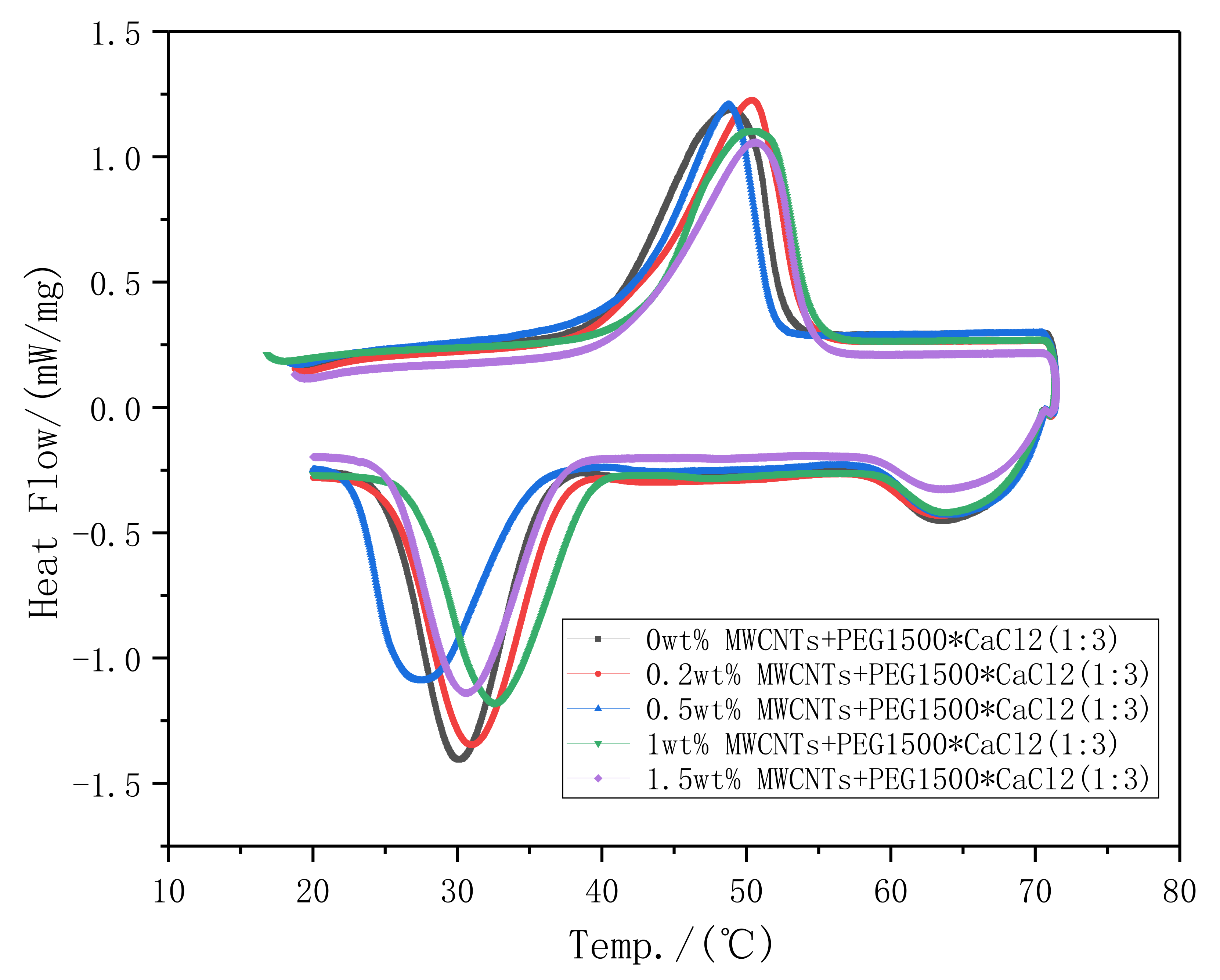
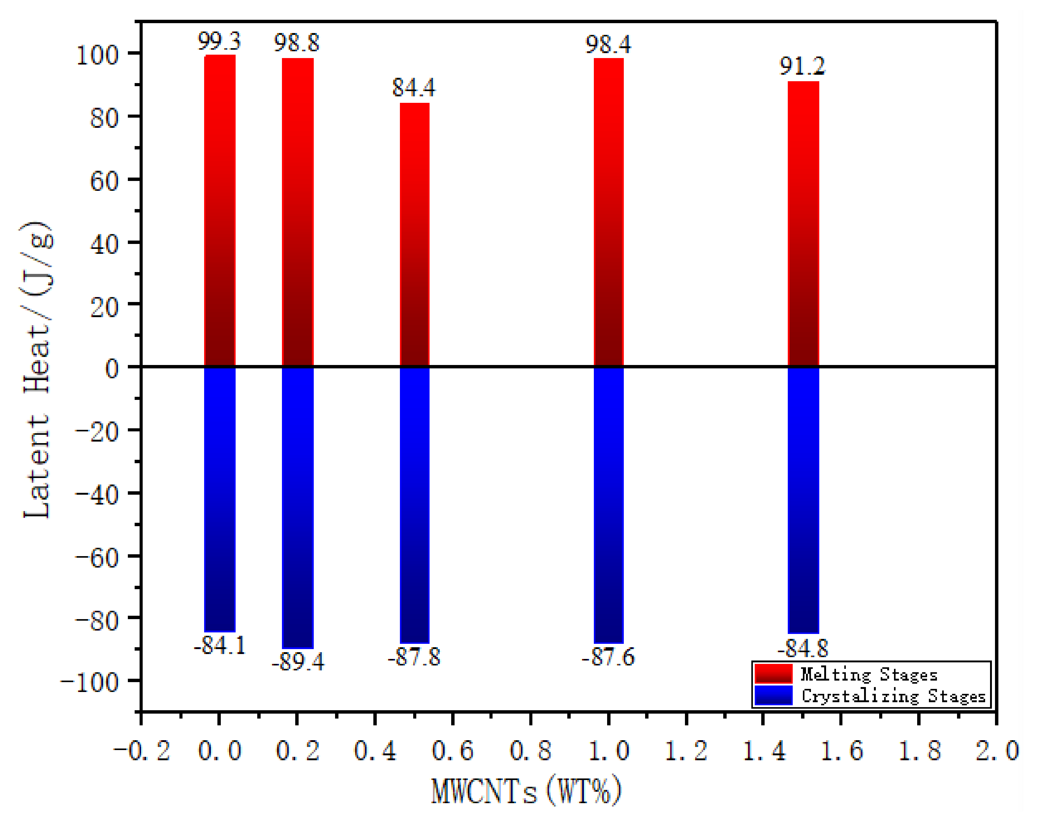
3.1.1. Latent Heat

Latent heat and phase change temperature are considered as the most important parameters of PCMs. The latent heat indicates the heat storage capacity of the PCMs. Suitable PCM should be considered according to the application temperature. The existing literature shows that CNTs suppress the mobility of matrix molecular chains by trapping phonons in the filler network, thereby resisting the phase changes [54]. Figure 2 shows the DSC curves recorded for the synthesized PEG1500·CaCl2(1:3)/MWCNTs Nwt% (1:X) samples during the melting and crystalizing stages, and Figure 3 shows the latent heat for the synthesized samples. The melting temperature of the complex without adding MWCNTs is 40.3 °C and its latent heat is 99.3 J/g. MWCNTs occupy the proportion of the phase change material in the 3D pore structure, the latent heat of the compound decreases with the increase of MWCNTs, when 0.2, 0.5, 1, and 1.5 wt% of MWCNT is added to the compound PCM, the latent heat of melting of the composite material is 98.8, 84.4, 98.4, and 91.2 J/g; compared with PEG1500·CaCl2, the latent heat value is decreased 0.5%, 15%, 0.9%, and 8.20%. With the increase of MWCNT content, the melting temperature of PEG1500·CaCl2(1:3)/MWCNTs N wt% increases slightly. When the content of MWCNTs is 1.5 wt%, the compound’s melting temperature is the largest, which is 42 °C. The phase change temperature of the compound material after adding MWCNTs is still within the seeking range (suitable for battery thermal management), and the latent heat is still at a relatively large value.
The crystallization stage curve of PEG1500·CaCl2(1:3)/MWCNTs’ is similar to the melting stage. With the increase of MWCNT mass, the crystallization temperature of composite PCMs began to increase and their latent heat decreased. It shows that the presence of carbon nanotubes affects the energy storage properties of the materials deeply.
Meanwhile, change trend of crystallinity can also be observed from Figure 2. Crystallinity Xc can be calculated by equation (Equation (3)):
X c % = H H × 100 %
where ΔH is the melting enthalpy of PCMs, J/g; H   is the melting enthalpy of 100% crystalline PCMs. H   would be unchanged for the same material, which means the presence of MWCNT reduces the crystallinity of composite PCMs.
An obvious phase change hysteresis is found. Normally we think the process of latent heat storage and released should be carried out at a constant temperature; however, due to the purity of the material and other reasons, PCM has a solid–liquid coexistence phenomenon at the melting point. Because of the thermal resistance, during the heating process, the internal sample’s temperature the is lower than the temperature of the surface, which may cause that the detected temperature is higher than real sample temperature during the heating process, then the surface temperature of the sample would be exceeded melting temperature, peak will move to a higher temperature. Conversely, during the cooling process, the sample temperature is lower than estimated, so the peak will shift to a lower temperature [55,56]. On the other hand, polymer materials are folded through molecular chains to form crystals of various sizes. Melting and crystallization process are in Gaussian distribution which leads to a hysteresis. Polymer crystals are different from inorganic salt crystals. The former is composed of crystals of different sizes, while the latter has the same crystal size and structure. For example, the PEG1500 used in this study is composed of long chains with an average molecular weight of 1350~1650. They emit different heat when recrystallized, so hysteresis occurs. Similar discoveries have also been reported [57].
Determination of the melting temperature range of PCM means to find the starting melting temperature at which PCM starts melting and the ending melting temperature at which the melting process is finished. However, the form-stable phase change material in this study does not show a melting state when it reaches the target temperature (Shape stability verification work would be shown in Section 3.2), which reduces the accuracy of the DSC test. However, the DSC sample quality is very small (5–10 mg), and the highest temperature measured is 70 °C which is higher than the phase change temperature nearly 30 °C. According to the test rate 5 °C/min, and we keep the constant temperature of 70 °C for 3 min, the sample has been kept above the phase transition temperature for 9 min, so the complete phase change process has been achieved. Then we believe that the DSC test results have reference value. The general way to improve the phase transition hysteresis is to reduce the test rate and let the sample melt completely [58]. According to previous reports, the oscillation amplitude of the surface temperature strongly affects the temperature distribution and boundary motion [59,60]. However, as mentioned above, the sample in this study will not melt into a liquid at the target temperature. We will explore a feasible research method for shaping phase change materials to improve the phenomenon of phase change hysteresis in future research.

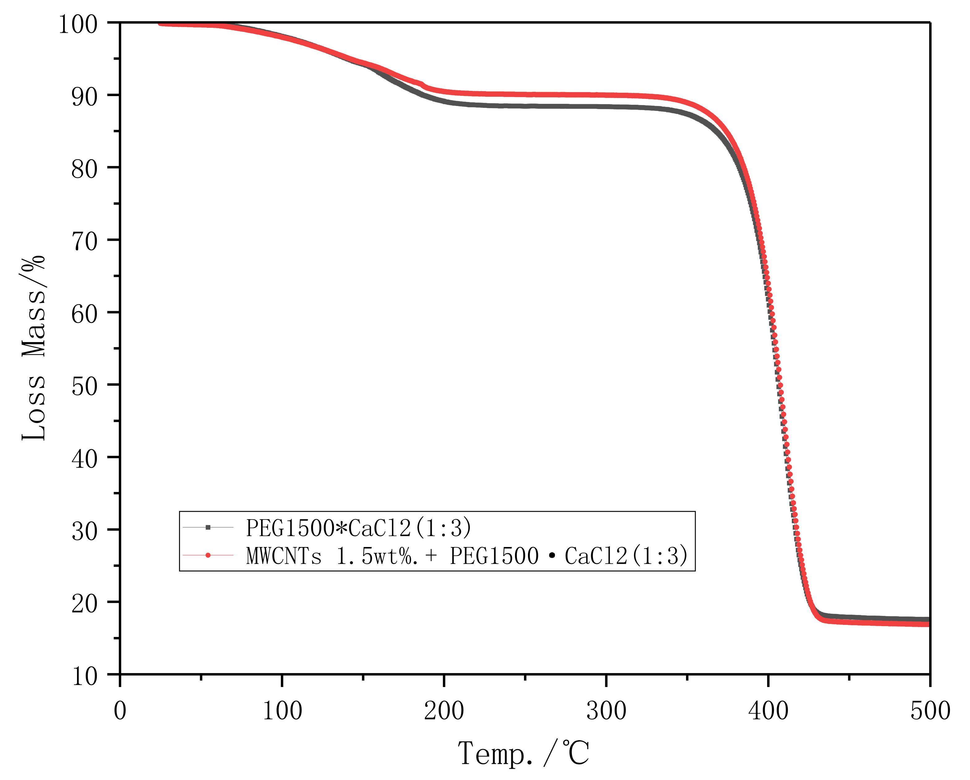
3.1.2. Thermal Stability Analysis

Thermal stability of form-stable PCMs was analyzed by thermogravimetric (TG), and test results are presented in Figure 4. According to TG curves, PEG1500·CaCl2(1:3) and PEG1500·CaCl2(1:3)/MWCNTs 1.5 wt% have a weak weight loss from 100 °C to 200 °C. A significant weight loss occurs after 350 °C. It shows that these two composite form-stable phase change materials have good thermal stability at high temperatures. These two curves almost overlap, indicating that MWCNTs does not help to improve the thermal stability of PEG1500·CaCl2 (1:3), which may be due to the low content.

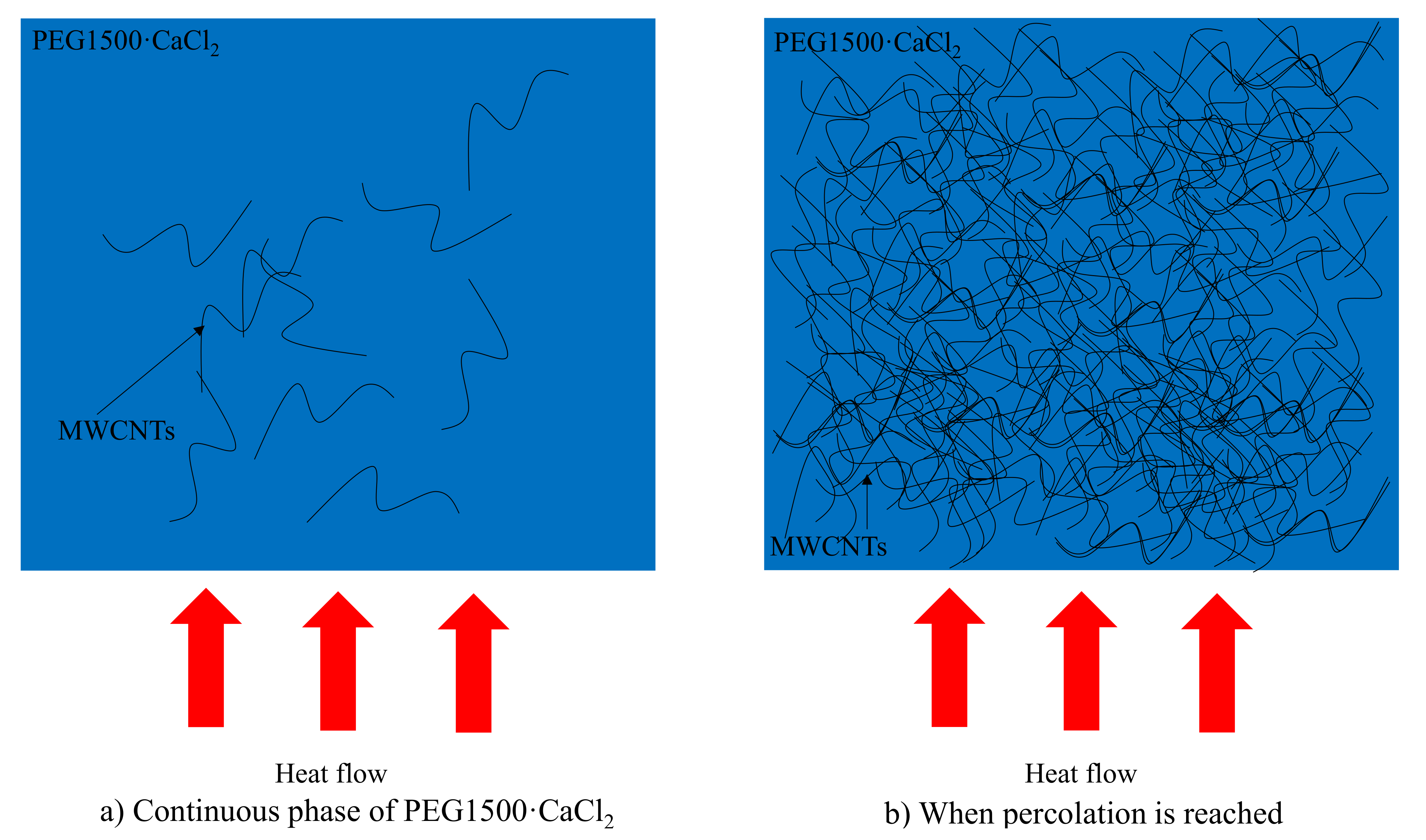
3.1.3. Thermal Conductivity

Due to their molecular chain arrangement and structure, polymer PCMs have low thermal conductivity (<0.5 W/(m·K)) [61,62,63]. Adding high thermal conductivity inorganic fillers is considered as an effective way to increase the thermal conductivity of polymer materials. As a kind of one-dimensional carbon materials with high thermal conductivity, in this article, carbon nanotubes will effectively improve PCMs’ thermal conductivity through the formation of double percolation thermal network. Figure 5 shows the thermal conductivity of the PEG1500·CaCl2(1:3)/MWCNTs Nwt% (1:X) PCM. It can be seen that the thermal conductivity of pure PEG1500·CaCl2 complex is 0.23 W/(m·K). When 0.2, 0.5, 1, 1.5 wt% MWCNTs are added into the compound PCM, the thermal conductivity of the compound material is 0.41, 0.64, 0.78, and 0.90 W/(m·K), compared with PEG1500·CaCl2 the thermal conductivity is increased by 78.26%, 178.26%, 239.13%, and 291.30%. It is obviously that the introduction of MWCNTs significantly improves the thermal conductivity of compound PEG1500·CaCl2.
The increase of thermal conductivity is due to the high thermal conductivity of MWCNTs. Normally, the thermal conductivity of organic PCMs is low, which is related to their heat conduction mechanism. They mainly rely on the mutual vibration of molecules to conduct heat, which is called phonon conduction. The carbon nanotube heat conduction system has a large average phonon free path [64], which can improve the mean free path (MFP) of phonons. Moreover, the added MWCNTs are in a micron size structure, and the interface thermal resistance is also very small. These factors will significantly increase the thermal conductivity of the original PCM.
Although the thermal conductivity of a single carbon nanotube is very high, in practical applications, the carbon nanotubes are assembled disorderly by van der Waals to form a carbon nanotube network. The overlap between the carbon nanotubes affects the thermal conductivity of the overall network, and MWCNTs are easy to entangle, bundle together, and agglomerate, which affect dispersed and thermal efficiency [65]. According to reports, the thermal conductivity of the carbon nanotube network can be as low as 0.134 W/(m·K) [66,67,68]. Zhong et al. [69] found through molecular dynamics simulation that the thermal contact resistance between carbon nanotubes decreases as the overlap interval decreases. One-dimensional MWCNTs’ thermal interfacial resistance R can be expressed by Equation (4):
R = A T / q
where A is the interface area ,   T is the steady-state temperature jump between two surfaces forming the interface, and q is the heat flow rate across the interface. Therefore, increasing A means enhancing thermal resistance R.
The PEG1500·CaCl2(1:3) matrix can also transmit the phonon vibration from MWCNTs to another MWCNTs more efficiently, so that the phonon conduction forms a faster chain and forms a more common heat conduction path. It reduces part of the thermal resistance of the carbon nanotube network caused by the overlapping form. Wang [70] et al. found that solid materials’ orderly structure could enhance heat transfer between TCNTs and PCMs that was due to decreasing thermal resistance. The significant increase in thermal conductivity could indicate the material has reached double percolation structure (Figure 6 shows Thermal conductivity double percolation mechanism of PEG1500·CaCl2(1:3)/MWCNTs). The double percolation structure, conductive fillers are selectively located in one phase of a co-continuous immiscible polymer blend to form a percolated conductive pathway in the selected phase. Two requirements are needed to realize the double percolation structure in composites. One requires co-continuous blend morphologies, the other needs selective filling of only one of the blend phases (double percolation). When the filler is distributed on the continuous interface of the co-continuous polymer blend, in this way, the filler required to establish an infiltration heat conduction network is minimized. It is expected to further improve its thermal conductivity. The double percolation structure provides a significant improvement in thermal conductivity. This composite material has a co-continuous structure and has a very low thermal permeability threshold (0.11 vol%); polymer matrix and thermally conductive fillers that do not have a double percolation structure usually require a very high load (30 vol%) to obtain a suitable Thermal Conductivity [71]. Zhang et al. [72] prepared an insulating three-phase double percolation BNNSs/SEBS/PP nanocomposites, after adding 3 phr BNNSs, the thermal conductivity of SEBS/PP was increased 228.6% (from 0.42 W/(m·K) to 1.38 W/(m·K)). This is because the SEBS phase with BNNSs can form a complete heat conduction pathway structures in the PP substrate. Wu et al. [73] combined EG and MWCNTs in polypropylene to prepare a double percolated filler network. The interface thermal resistance (Rk) is 4.27 × 10⁻⁷ m2 KW−1 when the MWCNT content is less than 2 wt%. The thermal conductivity of the PP/EG-MWCNT is lower than PP/EG-EG, which shows that when the MWCNT content does not reach the threshold, there is no obvious effective effect on improving the heat transfer performance. However, when the MWCNT content reaches 3 wt%, the interface thermal resistance (Rk) is only 2.93 × 10⁻⁸ m2 KW−1, and the effective thermal conductivity (ke/km) increases rapidly with the increase of MWCNT content.

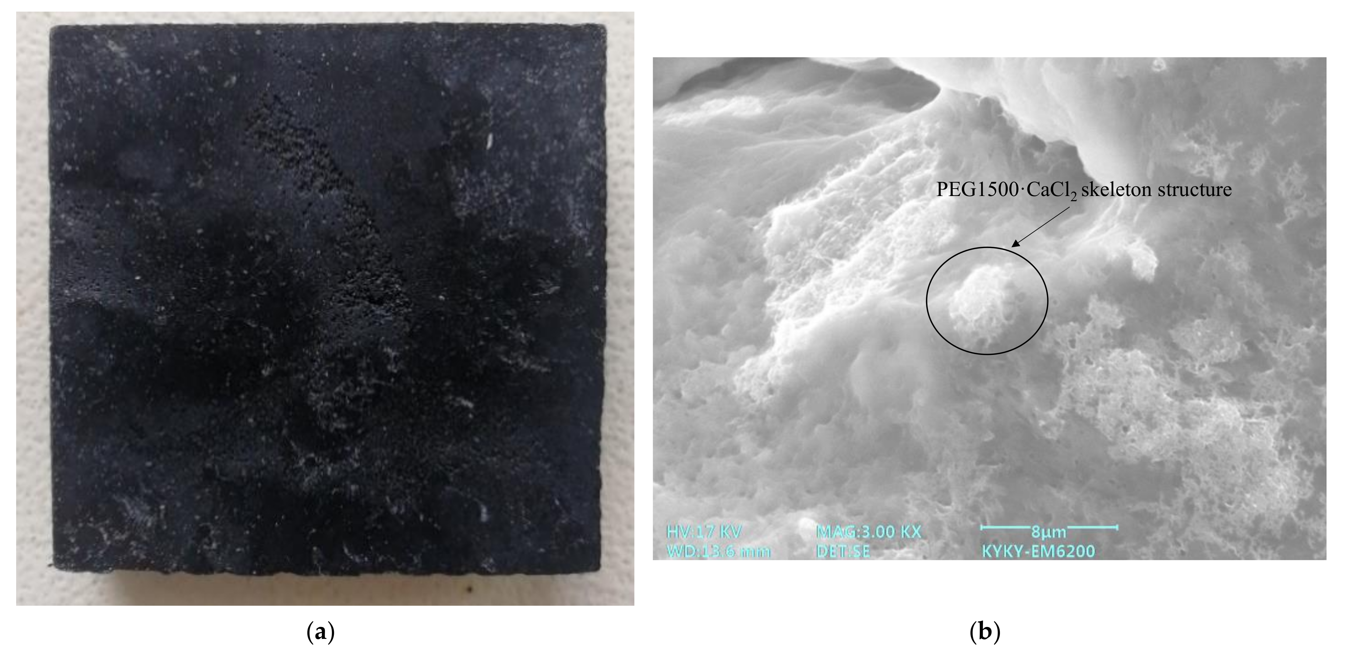
3.2. Shape Stability of PEG1500·CaCl2/MWCNTs Composites

In order to study the stability of PEG1500·CaCl2 (1:X), composite samples containing various load ratios were placed on the filter paper (Figure 7), and then each sample and the filter paper were placed in an oven at a temperature of 80 °C (above the melting point of polyethylene glycol) 2 h to ensure that the sample undergoes a phase change from solid to liquid. After cooling to room temperature, we observe each filter paper for any traces of liquid PEG leakage carefully. The shape of polymer PCMs during process from solid to liquid would change, materials are easily leaked without suitable package. This limits polymer PCMs used in the engineering field. Therefore, it is necessary to study the shape stability of polymer PCMs. At this stage, the shape stability of phase change materials can be ensured by cross-linking method [74,75,76,77], high specific surface area material adsorption method [78,79], microcapsule method and other methods [80,81,82]. The method used in this work is to cross-link PEG materials together by complexation. Although PEG crystalline phase changes from solid to liquid, the morphology of compounds is stable because of the existence of PEG1500·CaCl2 complex skeleton structure. Figure 8 shows the leakage diagram of PEG1500·CaCl2 PCM. As Figure 8 shows, with the increasing of CaCl2 content, the leakage of PEG1500·CaCl2 decrease gradually. The reason is that the more CaCl2 content, and the more complex points between PEG1500·CaCl2 3D skeleton and PEG, the less leakage of PCM. The diameter of carbon nanotubes is at the nanometer level and the specific surface area is very high. It must have a high adsorption effect on PEG polymer materials. Therefore, after adding carbon nanotubes, the PCM material will have higher deformation resistance. CaCl2 and CaCl2·PEG complexes do not have latent heat, the latent heat of compound PCMs depends on the value of the mass fraction of pure PEG adsorbed on the 3D framework. Therefore, the maximum PEG mass fraction (1:3) without leakage is chosen for further optimization.
The composite PEG1500·CaCl2(1:3)/MWCNTs and its microstructure are shown in Figure 9. We can see the white PEG1500·CaCl2 skeleton structure in the picture clearly, which is the key to maintaining the shape stability of PCMs.

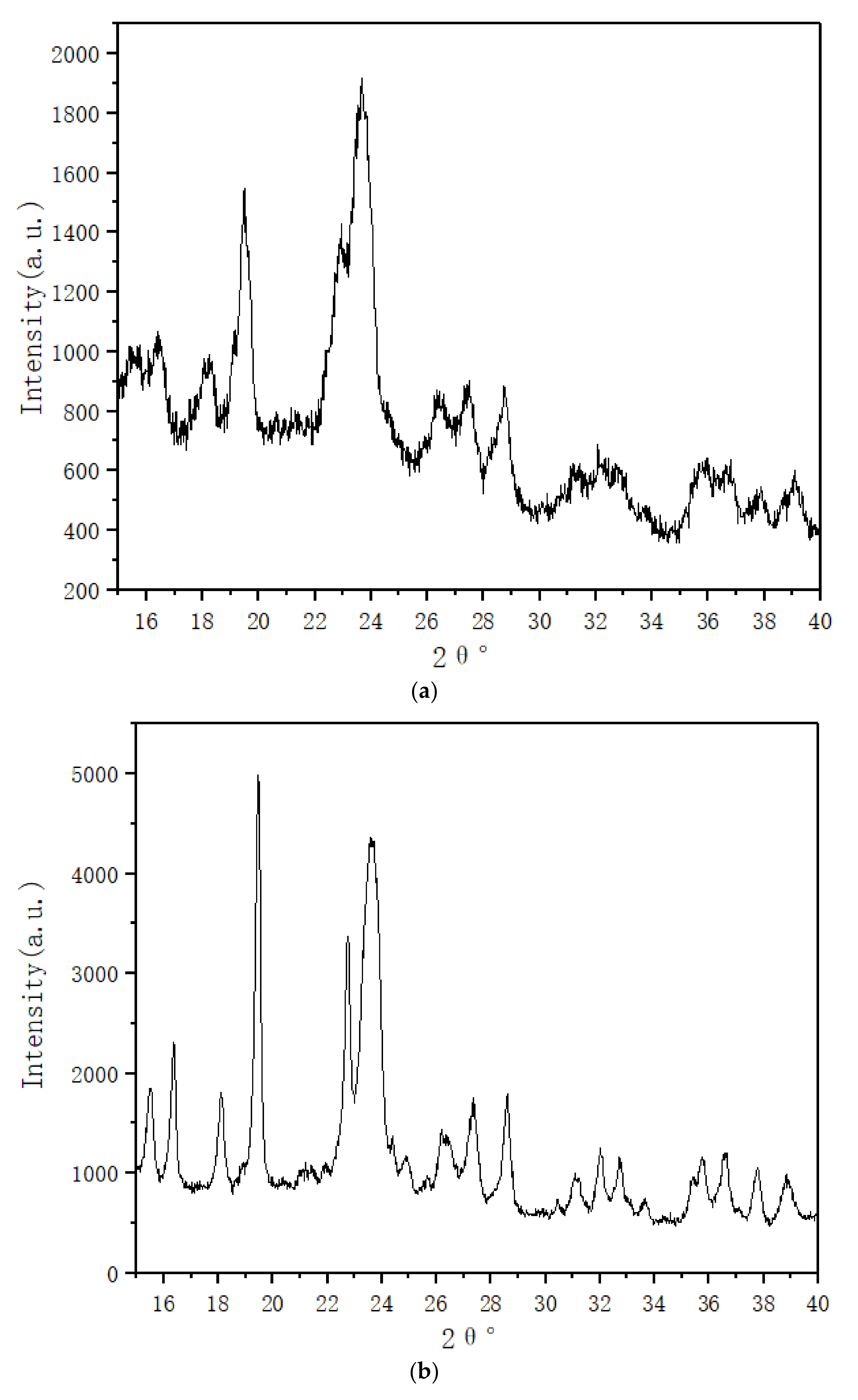
3.3. XRD and FT-IR Characterization

Figure 10 shows the XRD patterns of prepared pure PEG1500·CaCl2(1:3) and PEG1500·CaCl2(1:3)/MWCNTs 1.5 wt%. Pure PEG1500·CaCl2(1:3) compound exhibits two strong crystallization peaks at 19.22° and 23.32°. Meanwhile, the corresponding crystal diffraction peaks for the PEG1500·CaCl2(1:3)/MWCNTs 1.5 wt% sample are centered at 18.69° and 22.94°. These peak shapes of PEG1500·CaCl2(1:3) before and after adding MWCNTs do not change much, no other diffraction peaks appeared, indicating that additional MWCNTs do not affect the crystal structure of PEG1500·CaCl2 complex. After adding 1.5 wt% MWCNTs, these two main crystallization peaks of compound PCMs shift left 0.53 and 0.38. According to Prague equation (Equation (5)):
2dsinθ = nλ
In which d is crystal plane spacing, nm; θ describes the angle between the reflecting crystal plane and the incident X-ray, °; n is the reflected series; and λ is the wavelength of the X-ray, nm. Reduced angle suggests that MWCNTs increase the polymer interplanar spacing.
To further research the characteristic of composite phase change material, Fourier transform infrared spectroscopy (FT-IR) analyses were conducted for the PEG1500·CaCl2(1:3) and PEG1500·CaCl2(1:3)/MWCNTs 1.5 wt% sample. Theoretically, the stretching vibration of the OH group appears at 3650–3200 cm−1. When the hydroxy compound is associated, the absorption peak of the O-H group shifts to the low wavenumber direction. At this time, a broad and strong absorption peak appears at 3400–3200 cm−1. This is consistent with what we saw in Figure 11. It shows that the complex has an association reaction. However, the presence of MWCNTs did not effect on the wavelength after 1500 cm−1, it proves that MWCNTs will not affect the association reaction of the polymer.

4. Conclusions

In this paper, a new type of high thermal conductivity form-stable PCM was prepared. Series of methods such as differential scanning calorimetry (DSC), X-ray diffraction (XRD), and Hot Disk thermal constant analysis are used to study the effect of hydroxylated multi-walled carbon nanotubes on PEG1500·CaCl2.
(1)
Phase change temperature increases with the increasing of MWCNTs mass fraction, while the latent heat decreasing. non MWCNTs material’s phase change temperature is 40.3 °C, and its latent heat is 99.3 J/g, compared to PEG1500·CaCl2(1:3)/MWCNTs 1.5 wt% that has the highest phase change temperature (42 °C). An obvious phase change hysteresis is found, which due to the uneven size of polymer crystals, and the speed of the recrystallization process is different. The sample in this study will not melt into a liquid at the target temperature, which makes the internal heat transfer mechanism and rate of the sample inconsistent. During the heating process, the internal sample’s temperature the is lower than the temperature of the surface, and during the cooling process the sample temperature is lower than estimated, so the peak will shift to a lower temperature, aggravating the hysteresis of the DSC curve.
(2)
TG curve indicating that MWCNTs does not help to improve the thermal stability of PEG1500·CaCl2 (1:3), which may be due to the low content.
(3)
The thermal conductivity of pure PEG1500·CaCl2 is 0.23 W/(m·K). When 0.2, 0.5, 1, and 1.5 wt% MWCNTs are added, their thermal conductivities increase to 0.41, 0.64, 0.78, and 0.90 W/(m·K). This is due to the large average phonon free path of MWCNTs, which can improve the mean free path of phonons effectively, and the added MWCNTs effectively reduce the interface thermal resistance between PCM molecules. The results of this study also showed the thermal conductivity double percolation mechanism of PEG1500·CaCl2(1:3)/MWCNTs.
(4)
XRD patterns indicating that additional MWCNTs do not affect the crystal structure of PEG1500·CaCl2, but they increase the polymer interplanar spacing. FT-IR analyses shows that the complex has an association reaction.

Author Contributions

Writing—original draft preparation, L.Z.; writing—review and editing, W.H., X.W., and F.M.; project administration, X.Z. All authors have read and agreed to the published version of the manuscript.

Funding

This research was funded by Project of Shanghai Science and Technology Commission, grant number 19DZ1203102 and National Key R&D Project Plan, grant number 2018YFD0401300.

Data Availability Statement

The data presented in this study are available on request from the corresponding author.

Conflicts of Interest

The authors declare no conflict of interest.

References

  1. Pineda, I. Challenges and Opportunities in Renewable Energy Developments; Palgrave Macmillan: Cham, Switzerland, 2021. [Google Scholar]
  2. Fallahi, A.; Guldentops, G.; Tao, M.; Granados-Focil, S.; Van Dessel, S. Review on solid-solid phase change materials for thermal energy storage: Molecular structure and thermal properties. Appl. Therm. Eng. 2017, 127, 1427–1441. [Google Scholar] [CrossRef]
  3. Rostami, S.; Afrand, M.; Shahsavar, A.; Sheikholeslami, M.; Kalbasi, R.; Aghakhani, S.; Shadloo, M.S.; Oztop, H.F. A review of melting and freezing processes of PCM/nano-PCM and their application in energy storage. Energy 2020, 211. [Google Scholar] [CrossRef]
  4. Mao, Q.; Zhang, Y. Thermal energy storage performance of a three-PCM cascade tank in a high-temperature packed bed system. Renew. Energy 2020, 152, 110–119. [Google Scholar] [CrossRef]
  5. Manoj Kumar, P.; Mylsamy, K.; Saravanakumar, P.T. Experimental investigations on thermal properties of nano-SiO2/paraffin phase change material (PCM) for solar thermal energy storage applications. Energy Sourcespart A Recovery Util. Environ. Eff. 2019, 42, 2420–2433. [Google Scholar] [CrossRef]
  6. Liu, B.; Zhang, X.; Ji, J.; Hua, W.; Mao, F. Preparation and characterization of urea/ammonia bromide composite phase change material. Int. J. Energy Res. 2020, 44, 3626–3639. [Google Scholar] [CrossRef]
  7. Gholamibozanjani, G.; Farid, M. A comparison between passive and active PCM systems applied to buildings. Renew. Energy 2020, 162, 112–123. [Google Scholar] [CrossRef]
  8. Beemkumar, N.; Yuvarajan, D.; Arulprakasajothi, M.; Elangovan, K.; Arunkumar, T. Control of room temperature fluctuations in the building by incorporating PCM in the roof. J. Therm. Anal. Calorim. 2020. [Google Scholar] [CrossRef]
  9. Gholamibozanjani, G.; Farid, M. Application of an active PCM storage system into a building for heating/cooling load reduction. Energy 2020, 210, 118572. [Google Scholar] [CrossRef]
  10. Arshad, A.; Jabbal, M.; Sardari, P.T.; Bashir, M.A.; Faraji, H.; Yan, Y. Transient simulation of finned heat sinks embedded with PCM for electronics cooling. Therm. Sci. Eng. Prog. 2020, 18, 100520. [Google Scholar] [CrossRef]
  11. Reuben Raj, C.; Suresh, S.; Vasudevan, S.; Chandrasekar, M.; Kumar Singh, V.; Bhavsar, R.R. Thermal performance of nano-enriched form-stable PCM implanted in a pin finned wall-less heat sink for thermal management application. Energy Convers. Manag. 2020, 226, 113466. [Google Scholar] [CrossRef]
  12. Ren, Q.; Guo, P.; Zhu, J. Thermal management of electronic devices using pin-fin based cascade microencapsulated PCM/expanded graphite composite. Int. J. Heat Mass Transf. 2020, 149, 119119. [Google Scholar] [CrossRef]
  13. McCarthy, L.K.; di Marzo, M. The Application of Phase Change Material in Fire Fighter Protective Clothing. Fire Technol. 2011, 48, 841–864. [Google Scholar] [CrossRef]
  14. Du, J.; Nie, B.; Zhang, Y.; Du, Z.; Wang, l.; Ding, Y. Cooling performance of a thermal energy storage-based portable box for cold chain applications. J. Energy Storage 2020, 28, 101238. [Google Scholar] [CrossRef]
  15. Zhao, Y.; Zhang, X.; Xu, X.; Zhang, S. Research progress of phase change cold storage materials used in cold chain transportation and their different cold storage packaging structures. J. Mol. Liq. 2020, 319, 114360. [Google Scholar] [CrossRef]
  16. Wan, X.; Chen, C.; Tian, S.; Guo, B. Thermal characterization of net-like and form-stable ML/SiO2 composite as novel PCM for cold energy storage. J. Energy Storage 2020, 28, 101276. [Google Scholar] [CrossRef]
  17. Su, W.; Darkwa, J.; Kokogiannakis, G. Review of solid–liquid phase change materials and their encapsulation technologies. Renew. Sustain. Energy Rev. 2015, 48, 373–391. [Google Scholar] [CrossRef]
  18. Pielichowska, K.; Pielichowski, K. Phase change materials for thermal energy storage. Prog. Mater. Sci. 2014, 65, 67–123. [Google Scholar] [CrossRef]
  19. Ling, Z.; Chen, J.; Xu, T.; Fang, X.; Gao, X.; Zhang, Z. Thermal conductivity of an organic phase change material/expanded graphite composite across the phase change temperature range and a novel thermal conductivity model. Energy Convers. Manag. 2015, 102, 202–208. [Google Scholar] [CrossRef] [Green Version]
  20. Wei, G.; Wang, G.; Xu, C.; Ju, X.; Xing, L.; Du, X.; Yang, Y. Selection principles and thermophysical properties of high temperature phase change materials for thermal energy storage: A review. Renew. Sustain. Energy Rev. 2018, 81, 1771–1786. [Google Scholar] [CrossRef]
  21. Yu, Q.; Tchuenbou-Magaia, F.; Al-Duri, B.; Zhang, Z.; Ding, Y.; Li, Y. Thermo-mechanical analysis of microcapsules containing phase change materials for cold storage. Appl. Energy 2018, 211, 1190–1202. [Google Scholar] [CrossRef] [Green Version]
  22. Weng, J.; Ouyang, D.; Yang, X.; Chen, M.; Zhang, G.; Wang, J. Alleviation of thermal runaway propagation in thermal management modules using aerogel felt coupled with flame-retarded phase change material. Energy Convers. Manag. 2019, 200, 112071. [Google Scholar] [CrossRef]
  23. Kumar, U.A.; Satyanarayana PV, V.; Srikanth, T. Influence of Polyethylene Glycol on Asphaltic Concrete for Cubical and Rod shaped Aggregates. J. Eng. Res. Appl. 2014, 4, 6. [Google Scholar]
  24. Jiang, Y.; Ding, E.; Li, G. Study on transition characteristics of PEG/CDA solid–solid phase change materials. Polymer 2002, 43, 5. [Google Scholar] [CrossRef]
  25. Paberit, R.; Rilby, E.; Göhl, J.; Swenson, J.; Refaa, Z.; Johansson, P.; Jansson, H. Cycling Stability of Poly(ethylene glycol) of Six Molecular Weights: Influence of Thermal Conditions for Energy Applications. ACS Appl. Energy Mater. 2020, 3, 10578–10589. [Google Scholar] [CrossRef]
  26. Sarier, N.; Onder, E. Organic phase change materials and their textile applications: An overview. Thermochim. Acta 2012, 540, 7–60. [Google Scholar] [CrossRef]
  27. Tas, C.E.; Unal, H. Thermally buffering polyethylene/halloysite/phase change material nanocomposite packaging films for cold storage of foods. J. Food Eng. 2021, 292. [Google Scholar] [CrossRef]
  28. Umair, M.M.; Zhang, Y.; Iqbal, K.; Zhang, S.; Tang, B. Novel strategies and supporting materials applied to shape-stabilize organic phase change materials for thermal energy storage—A review. Appl. Energy 2019, 235, 846–873. [Google Scholar] [CrossRef]
  29. Chen, K.; Wang, C.; Wang, T.; Zhu, Z.; Ma, R.; Jiang, H. Preparation and performances of form-stable polyethylene glycol/methylcellulose composite phase change materials. J. Polym. Res. 2020, 27. [Google Scholar] [CrossRef]
  30. Meng, Y.; Majoinen, J.; Zhao, B.; Rojas, O.J. Form-stable phase change materials from mesoporous balsa after selective removal of lignin. Compos. Part B Eng. 2020, 199. [Google Scholar] [CrossRef]
  31. Fang, H.; Lin, J.; Zhang, L.; Chen, A.; Wu, F.; Geng, L.; Peng, X. Fibrous form-stable phase change materials with high thermal conductivity fabricated by interfacial polyelectrolyte complex spinning. Carbohydr. Polym. 2020, 249, 116836. [Google Scholar] [CrossRef]
  32. Zhang, H.; Sun, Q.; Yuan, Y.; Zhang, Z.; Cao, X. A novel form-stable phase change composite with excellent thermal and electrical conductivities. Chem. Eng. J. 2018, 336, 342–351. [Google Scholar] [CrossRef]
  33. Heyhat, M.M.; Mousavi, S.; Siavashi, M. Battery thermal management with thermal energy storage composites of PCM, metal foam, fin and nanoparticle. J. Energy Storage 2020, 28. [Google Scholar] [CrossRef]
  34. Sardari, P.T.; Babaei-Mahani, R.; Giddings, D.; Yasseri, S.; Moghimi, M.A.; Bahai, H. Energy recovery from domestic radiators using a compact composite metal Foam/PCM latent heat storage. J. Clean. Prod. 2020, 257. [Google Scholar] [CrossRef]
  35. Zhao, Y.; Jin, L.; Zou, B.; Qiao, G.; Zhang, T.; Cong, L.; Jiang, F.; Li, C.; Huang, Y.; Ding, Y. Expanded graphite—Paraffin composite phase change materials: Effect of particle size on the composite structure and properties. Appl. Therm. Eng. 2020, 171. [Google Scholar] [CrossRef]
  36. Yang, Y.; Pang, Y.; Liu, Y.; Guo, H. Preparation and thermal properties of polyethylene glycol/expanded graphite as novel form-stable phase change material for indoor energy saving. Mater. Lett. 2018, 216, 220–223. [Google Scholar] [CrossRef]
  37. Zhang, S.; Zhang, X.; Xu, X.; Zhao, Y. Experimental study on the storage and release characteristics of phase change materials with different nanomaterials as addictives. Heat Mass Transf. 2020, 56, 2769–2777. [Google Scholar] [CrossRef]
  38. Bandini, M.; Benaglia, M.; Sinisi, R.; Tommasi, S.; Umani-Ronchi, A. Recoverable PEG-supported copper catalyst for highly stereocontrolled nitroaldol condensation. Org. Lett. 2010, 9, 2151–2153. [Google Scholar] [CrossRef]
  39. Zheng, J.; Smith Callahan, L.A.; Hao, J.; Guo, K.; Wesdemiotis, C.; Weiss, R.A.; Becker, M.L. Strain-Promoted Cross-Linking of PEG-Based Hydrogels via Copper-Free Cycloaddition. ACS Macro Lett. 2012, 1, 1071. [Google Scholar] [CrossRef] [Green Version]
  40. Qian, T.; Li, J.; Min, X.; Guan, W.; Deng, Y.; Ning, L. Enhanced thermal conductivity of PEG/diatomite shape-stabilized phase change materials with Ag nanoparticles for thermal energy storage. J. Mater. Chem. A 2015, 3, 8526–8536. [Google Scholar] [CrossRef]
  41. Pitie, F.; Zhao, C.Y.; Caceres, G. Thermo-mechanical analysis of ceramic encapsulated phase-change-material (PCM) particles. Energy Environ. Ence 2011, 4, 2117–2124. [Google Scholar] [CrossRef]
  42. Fukahori, R.; Nomura, T.; Zhu, C.; Sheng, N.; Okinaka, N.; Akiyama, T. Thermal analysis of Al–Si alloys as high-temperature phase-change material and their corrosion properties with ceramic materials. Appl. Energy 2016, 163, 1–8. [Google Scholar] [CrossRef]
  43. Koo, K.; Choe, J.; Park, Y. The application of PCMMcs and SiC by commercially direct dual-complex coating on textile polymer. Appl. Surf. Sci. 2009, 255, 8313–8318. [Google Scholar] [CrossRef]
  44. Mishra, A.K.; Lahiri, B.B.; Philip, J. Carbon black nano particle loaded lauric acid-based form-stable phase change material with enhanced thermal conductivity and photo-thermal conversion for thermal energy storage. Energy 2020, 191, 116572. [Google Scholar] [CrossRef]
  45. Mishra, A.K.; Lahiri, B.B.; Philip, J. Superior thermal conductivity and photo-thermal conversion efficiency of carbon black loaded organic phase change material—ScienceDirect. J. Mol. Liq. 2019, 285, 640–657. [Google Scholar] [CrossRef]
  46. Kumaresan, V.; Velraj, R.; Das, S.K. The effect of carbon nanotubes in enhancing the thermal transport properties of PCM during solidification. Heat Mass Transf. 2012, 48, 1345–1355. [Google Scholar] [CrossRef]
  47. Lian, C.; Wang, B.; Chen, J.; Yong, Q.; Huang, Y.; Liao, B. Dispersion of Multi-Walled Carbon Nanotubes by Polymers with Carbazole Pendants. J. Phys. Chem. B 2017, 121, 8408–8416. [Google Scholar] [CrossRef]
  48. Liang, J.; Jeyasingh, R.G.D.; Chen, H.Y.; Wong, H.S.P. An Ultra-Low Reset Current Cross-Point Phase Change Memory With Carbon Nanotube Electrodes. IEEE Trans. Electron Devices 2012, 59, 1155–1163. [Google Scholar] [CrossRef]
  49. Frusteri, F.; Leonardi, V.; Vasta, S.; Restuccia, G. Thermal conductivity measurement of a PCM based storage system containing carbon fibers. Appl. Therm. Eng. 2005, 25, 1623–1633. [Google Scholar] [CrossRef]
  50. Mayani, S.V.; Mayani, V.J.; Kim, S.W. Development of novel porous carbon frameworks through hydrogen-bonding interaction and its ethylene adsorption activity. J. Porous Mater. 2012, 19, 519–527. [Google Scholar] [CrossRef]
  51. Guangyu, C.; Quanfang, C. Characterization Study of the Thermal Conductivity of Carbon Nanotube Copper Nanocomposites. J. Compos. Mater. 2010, 44, 2863–2873. [Google Scholar] [CrossRef]
  52. Magendran, S.S.; Khan, F.S.A.; Mubarak, N.M.; Khalid, M.; Walvekar, R.; Abdullah, E.C.; Nizamuddin, S.; Karri, R.R. Synthesis of organic phase change materials by using carbon nanotubes as filler material. Nano Struct. Nano Objects 2019, 19. [Google Scholar] [CrossRef]
  53. Cao, R.; Chen, S.; Wang, Y.; Han, N.; Liu, H.; Zhang, X. Functionalized carbon nanotubes as phase change materials with enhanced thermal, electrical conductivity, light-to-thermal, and electro-to-thermal performances. Carbon 2019, 149, 263–272. [Google Scholar] [CrossRef]
  54. Sagar, S. MWCNTS Incorporated Natural Rubber Composites: Thermal Insulation, Phase Transition and Mechanical Properties. Int. J. Eng. Technol. 2014, 6, 168–173. [Google Scholar] [CrossRef] [Green Version]
  55. Barz, T.; Sommer, A. Modeling hysteresis in the phase transition of industrial-grade solid/liquid PCM for thermal energy storages. Int. J. Heat Mass Transf. 2018, 127, 701–713. [Google Scholar] [CrossRef]
  56. Gomez-Heredia, C.L.; Ramirez-Rincon, J.A.; Bhardwaj, D.; Rajasekar, P.; Tadeo, I.J.; Cervantes-Lopez, J.L.; Ordonez-Miranda, J.; Ares, O.; Umarji, A.M.; Drevillon, J.; et al. Measurement of the hysteretic thermal properties of W-doped and undoped nanocrystalline powders of VO2. Sci. Rep. 2019, 9, 14687. [Google Scholar] [CrossRef] [Green Version]
  57. Tariq, M.; Hameed, S.; Bechtold, I.H.; Bortoluzzi, A.J.; Merlo, A.A. Synthesis and characterization of some novel tetrazole liquid crystals. J. Mater. Chem. C 2013, 1. [Google Scholar] [CrossRef] [Green Version]
  58. Jin, X.; Xu, X.; Zhang, X.; Yin, Y. Determination of the PCM melting temperature range using DSC. Thermochim. Acta 2014, 595, 17–21. [Google Scholar] [CrossRef]
  59. Ivanovic, M.; Svicevic, M.; Savovic, S. Numerical solution of Stefan problem with variable space grid method based on mixed finite element/finite difference approach. Int. J. Numer. Methods Heat Fluid Flow 2017, 27, 2682–2695. [Google Scholar] [CrossRef]
  60. Savović, S.; Caldwell, J. Finite difference solution of one-dimensional Stefan problem with periodic boundary conditions. Int. J. Heat Mass Transf. 2003, 46, 2911–2916. [Google Scholar] [CrossRef]
  61. Li, R.; Shan, Z. Enhancement of thermal conductivity of PEG-PPG-based waterborne polyurethane coating by incorporating ordered polyethylene glycol fragment. Polym. Test. 2018, S0142941818301247. [Google Scholar] [CrossRef]
  62. Han, W.; Ge, C.; Zhang, R.; Ma, Z.; Wang, L.; Zhang, X. Boron nitride foam as a polymer alternative in packaging phase change materials: Synthesis, thermal properties and shape stability. Appl. Energy 2019, 238, 942–951. [Google Scholar] [CrossRef]
  63. Bahrani, S.A.; Royon, L.; Abou, B.; Osipian, R.; Azzouz, K.; Bontemps, A. A phenomenological approach of solidification of polymeric phase change materials. J. Appl. Phys. 2017, 121, 035103. [Google Scholar] [CrossRef]
  64. Sääskilahti, K.; Oksanen, J.; Volz, S.; Tulkki, J. Frequency-dependent phonon mean free path in carbon nanotubes from nonequilibrium molecular dynamics. Phys. Rev. B 2015, 91. [Google Scholar] [CrossRef] [Green Version]
  65. Cui, Y.; Liu, C.; Hu, S.; Yu, X. The experimental exploration of carbon nanofiber and carbon nanotube additives on thermal behavior of phase change materials. Sol. Energy Mater. Sol. Cells 2011, 95, 1208–1212. [Google Scholar] [CrossRef]
  66. Prasher, R.S.; Hu, X.J.; Chalopin, Y.; Mingo, N.; Lofgreen, K.; Volz, S.; Cleri, F.; Keblinski, P. Turning Carbon Nanotubes from Exceptional Heat Conductors into Insulators. Phys. Rev. Lett. 2009, 102, 105901. [Google Scholar] [CrossRef]
  67. Kalidoss, P.; Venkatachalapathy, S.; Suresh, S. Optical and Thermal Properties of Therminol 55-TiO2 Nanofluids for Solar Energy Storage. Int. J. Photoenergy 2020, 2020, 7085497. [Google Scholar] [CrossRef] [Green Version]
  68. Vasilev, A.; Lorenz, T.; Breitkopf, C. Thermal Conductivity of Polyisoprene and Polybutadiene from Molecular Dynamics Simulations and Transient Measurements. Polymers 2020, 12, 1081. [Google Scholar] [CrossRef]
  69. Zhong, H.; Lukes, J.R. Interfacial thermal resistance between carbon nanotubes: Molecular dynamics simulations and analytical thermal modeling. Phys. Rev. B Condens. Matter 2006, 74, 125403. [Google Scholar] [CrossRef] [Green Version]
  70. Wang, J.; Xie, H.; Xin, Z.; Li, Y.; Chen, L. Enhancing thermal conductivity of palmitic acid based phase change materials with carbon nanotubes as fillers. Sol. Energy 2010, 84, 339–344. [Google Scholar] [CrossRef]
  71. Huang, J.; Zhu, Y.; Xu, L.; Chen, J.; Jiang, W.; Nie, X. Massive enhancement in the thermal conductivity of polymer composites by trapping graphene at the interface of a polymer blend. Compos. Sci. Technol. 2016, 129, 160–165. [Google Scholar] [CrossRef]
  72. Zhang, D.-L.; Zha, J.-W.; Li, C.-Q.; Li, W.-K.; Wang, S.-J.; Wen, Y.; Dang, Z.-M. High thermal conductivity and excellent electrical insulation performance in double-percolated three-phase polymer nanocomposites. Compos. Sci. Technol. 2017, 144, 36–42. [Google Scholar] [CrossRef]
  73. Wu, K.; Xue, Y.; Yang, W.; Chai, S.; Chen, F.; Fu, Q. Largely enhanced thermal and electrical conductivity via constructing double percolated filler network in polypropylene/expanded graphite—Multi-wall carbon nanotubes ternary composites. Compos. Sci. Technol. 2016, 130, 28–35. [Google Scholar] [CrossRef]
  74. Hawlader, M.N.A.; Uddin, M.S.; Khin, M.M. Microencapsulated PCM thermal-energy storage system. Appl. Energy 2003, 74, 195–202. [Google Scholar] [CrossRef]
  75. Shirin-Abadi, A.R.; Mahdavian, A.R.; Khoee, S. New Approach for the Elucidation of PCM Nanocapsules through Miniemulsion Polymerization with an Acrylic Shell. Macromolecules 2011, 44, 7405–7414. [Google Scholar] [CrossRef]
  76. Ma, X.H.; Xu, Z.L.; Ji, C.Q.; Wei, Y.M.; Yang, H. Characterization, separation performance, and model analysis of STPP-chitosan/PAN polyelectrolyte complex membranes. J. Appl. Polym. Sci. 2011, 120, 1017–1026. [Google Scholar] [CrossRef]
  77. Mu, S.; Guo, J.; Zhang, S.; An, Q.; Wang, D.; Liu, Y.; Guan, F. Preparation and thermal properties of cross-linked poly(acrylonitrile-co-itaconate)/polyethylene glycol as novel form-stable phase change material for thermal energy storage. Mater. Lett. 2016, 171, 23–26. [Google Scholar] [CrossRef]
  78. Song, Y.; Zhang, N.; Jing, Y.; Cao, X.; Yuan, Y.; Haghighat, F. Experimental and numerical investigation on dodecane/expanded graphite shape-stabilized phase change material for cold energy storage. Energy 2019, 189, 116175. [Google Scholar] [CrossRef]
  79. Ren, X.; Shen, H.; Yang, Y.; Yang, J. Study on the properties of a novel shape-stable epoxy resin sealedexpanded graphite/paraffin composite PCM and itsapplication in buildings. Phase Transit. 2019, 92, 581–594. [Google Scholar] [CrossRef]
  80. Ng, D.Q.; Tseng, Y.L.; Shih, Y.F.; Lian, H.Y.; Yu, Y.H. Synthesis of novel phase change material microcapsule and its application. Polymer 2017, 133, 250–262. [Google Scholar] [CrossRef]
  81. Basal, G.; Deveci, S.S.; Yalcin, D.; Bayraktar, O. Properties of n-Eicosane-Loaded Silk Fibroin-Chitosan Microcapsules. J. Appl. Polym. Sci. 2011, 121, 1885–1889. [Google Scholar] [CrossRef] [Green Version]
  82. Fan, F.; Zhang, W.; Wang, C. Covalent bonding and photochromic properties of double-shell polyurethane-chitosan microcapsules crosslinked onto cotton fabric. Cellulose 2015, 22, 1427–1438. [Google Scholar] [CrossRef]
Figure 1. Preparation process diagram of PEG1500·CaCl2(1:3)/multi-walled carbon nanotubes (MWCNTs) composite materials.
Energies 14 01403 g001
Figure 2. Differential scanning calorimetry (DSC) curves recorded for the synthesized PEG1500·CaCl2(1:3)/MWCNTs Nwt% (1:X) samples.
Energies 14 01403 g002
Figure 3. Latent heat for the synthesized PEG1500·CaCl2(1:3)/MWCNTs Nwt% (1:X) samples.
Energies 14 01403 g003
Figure 4. Thermogravimetric (TG) curves recorded of PEG1500·CaCl2(1:3) and PEG1500·CaCl2(1:3)/MWCNTs 1.5 wt%.
Energies 14 01403 g004
Figure 5. Thermal conductivity for the synthesized PEG1500·CaCl2(1:3)/MWCNTs Nwt% (1:X).
Energies 14 01403 g005
Figure 6. Thermal conductivity double percolation mechanism of PEG1500·CaCl2(1:3)/MWCNTs (a) dispersion State (b) double percolation state.
Energies 14 01403 g006
Figure 7. Digital photos of morphologies of different samples.
Energies 14 01403 g007
Figure 8. Digital photos of morphologies of different samples at 80 °C for 2 h.
Energies 14 01403 g008
Figure 9. (a) Composite PEG1500·CaCl2(1:3)/MWCNTs (b) microstructure of PEG1500·CaCl2(1:3)/MWCNTs.
Energies 14 01403 g009
Figure 10. X-ray diffraction (XRD) patterns of: (a) PEG1500·CaCl2(1:3)/MWCNTs 0 wt%; (b) PEG1500·CaCl2(1:3)/MWCNTs 1.5 wt%.
Energies 14 01403 g010
Figure 11. Fourier transform infrared spectroscopy (FT-IR) patterns of PEG1500·CaCl2(1:3) and PEG1500·CaCl2(1:3)/MWCNTs 1.5 wt%.
Energies 14 01403 g011
Publisher’s Note: MDPI stays neutral with regard to jurisdictional claims in published maps and institutional affiliations.

