Article

A Solution to Pressure Equation with Its Boundary Condition of Combining Tangential and Normal Pressure Relations

School of Energy and Power Engineering, Huazhong University of Science and Technology, Wuhan 430074, China
*
Author to whom correspondence should be addressed.
Energies 2021, 14(5), 1507; https://doi.org/10.3390/en14051507
Submission received: 26 January 2021 / Revised: 5 March 2021 / Accepted: 6 March 2021 / Published: 9 March 2021
(This article belongs to the Section J: Thermal Management)

Abstract

:
Pressure is a physical quantity that is indispensable in the study of transport phenomena. Previous studies put forward a pressure constitutive law and constructed a partial differential equation on pressure to study the convection with or without heat and mass transfer. In this paper, a numerical algorithm was proposed to solve this pressure equation by coupling with the Navier-Stokes equation. To match the pressure equation, a method of dealing with pressure boundary condition was presented by combining the tangential and normal direction pressure relations, which should be updated dynamically in the iteration process. Then, a solution to this pressure equation was obtained to bridge the gap between the mathematical model and a practical numerical algorithm. Through numerical verification in a circular tube, it is found that the proposed boundary conditions are applicable. The results demonstrate that the present pressure equation well describes the transport characteristics of the fluid.

1. Introduction

Transport phenomena plays an important role in industrial processes and our daily life, including absorption, drying, heating, cooling, fluid flow, heat and mass transfer, etc., [1]. Researchers around the world have investigated a lot for revealing the mechanism of momentum, heat, and mass transports [2,3,4]. In practical convective heat and mass transfer applications, it is an important research project to enhance convective heat and mass transfer with low power consumption, and pressure transport is of great significance.
As we know that, in convective heat and mass transfer, there exist four physical quantities, i.e., temperature, velocity, concentration and pressure. Although much attention had been paid to the conservation equations in terms of temperature, velocity and concentration, to authors’ knowledge, the pressure equation was seldom considered by researchers. The transport mechanism of pressure in the convection has not been completely unveiled yet. Although the pressure Poisson equation has been derived from the Navier-Stokes (N-S) equation [5,6,7,8,9], the physical meaning of this equation is not clear. The mysterious pressure puzzles scientists and engineers, and even hinders the theory development of the convection with or without heat and mass transfer. That is to say, it is urgent to elaborate the constitutive relation of pressure and develop a pressure equation with boundary conditions so as to mature transport law of pressure.
On the other hand, the numerical simulation has become an important method for scientific research and engineering application. Avila et al. [10] studied the onset of turbulence in the pipe flow with direct numerical simulation. Barkley et al. [11] subsequently revealed the rise of fully turbulent flow with direct numerical simulation and experiment. Shishkina et al. [12] reported the Prandtl number dependencies of the laminar convective heat transport based on direct numerical simulation. Computational fluid dynamics is also widely applied in convective heat transfer enhancement [13,14,15,16,17]. In the past few decades, due to the lack of available pressure partial differential equation, continuity equation had been introduced to guarantee the coupling of pressure and velocity, in order to obtain the numerical solution of incompressible fluid flow. Thus, the SIMPLE series algorithms were proposed and had been widely used in simulating convective heat and mass transfer [18,19,20,21]. For the purpose of improving the robustness and economy of these algorithms, many researchers made constant efforts to improve the coupling of pressure and velocity [22,23,24,25], and proposed some revised methods [26,27,28].
However, the inherent difficulty of pressure and velocity coupling still exists and bothers researchers. In fact, the continuity equation, as a conditional equation, is very different from the momentum and energy conservation equations, which is a prerequisite to be satisfied in the fluid flow with or without heat and mass transfer. In form, it only involves velocity and lacks a diffusion term. In numerical simulation, it cannot be discretely transformed as a linear algebraic equation. Thus, the governing equations of the convection are not mathematically closed due to the lack of pressure partial differential equation and corresponding boundary conditions. Consequently, the coupling of pressure and velocity is indirect, which may cause the algorithms low convergence rate and deteriorated robustness. Some researchers had been devoted to the pressure Poisson equation to build numerical algorithms for incompressible fluid [5,6,7,8,9]. However, due to the complicated expression in this equation, it is not easy to find a solution. Besides, the velocity divergence may not always be zero in the numerical calculation. Thus, the solution to the pressure Poisson equation has not been applicable as a general algorithm yet. This motivates us to develop a partial differential equation in terms of pressure, and explore a numerical algorithm by directly coupling pressure and velocity.
In the field of convective heat transfer enhancement, Guo et al. [29,30] proposed field synergy principle to evaluate heat transfer enhancement by introducing a synergy angle between velocity vector and temperature gradient. Subsequently, Tao et al. [31,32,33] performed many numerical researches on the field synergy principle. Furthermore, to reduce power consumption of the fluid, Liu et al. [34,35,36,37] proposed the multi-field synergy principle and optimized convective heat transfer with variation method in the tube. In addition, Chen et al. [38,39] also optimized convective heat transfer with variation method. Recently, on the basis of previous theoretic works, Liu et al. [40] proposed a pressure equation that can reflect transport characteristics of the pressure. Thus, the governing equations involving velocity, pressure, temperature and concentration seems to be completed. In Ref. [40], however, the pressure boundary was given as constant values obtained from the SIMPLE algorithm.
The pressure equation proposed in Ref. [40] is meaningful in physics, which has a potential for developing a useful algorithm. However, there is a gap between the mathematical equation and an applicable algorithm. In this study, the most important issue is how to deal with the boundary conditions for the pressure equation. Only if the pressure boundary conditions are imposed properly, the solution to this equation could be obtained and a general algorithm could be completed for computational fluid dynamics. Therefore, the present work is aimed to solve the pressure equation with the proper boundary conditions that are based on the tangential and normal direction relations for pressure on the tube wall.

2. Pressure Equations

2.1. Present Pressure Equation

As it is stated by Liu et al. [40], the constitutive law of pressure is defined as
ω   =   ζ p ,
where ω represents the magnitude and direction of power flux, reflecting the ability of the fluid to do work, W/m2. ζ is power factor or power diffusion coefficient of the fluid, m2/s. As a physical property parameter of the fluid, it does not vary with the geometry and flow conditions, but may vary with the temperature of the fluid.
The power flux of the fluid can be also written as
ω   =   ζ p x i     ζ p y j     ζ p z k .
Due to viscous dissipation and kinetic energy loss in the fluid flow, the ability to do work changes correspondingly. The variation of power flux can be obtained as
ω   =   ( x i   +   y j   +   z k ) ( ζ p x i     ζ p y j     ζ p z k )   =   ζ 2 p .
On the other hand, the viscous dissipation and kinetic energy variation of the fluid can be expressed as
U ( p )   =   U ( ρ U U μ 2 U ) ,
where U ( p ) denotes mechanical energy provided by the pump or fan.
Thus, according to the fact that the supplied mechanical energy is equivalent to the energy consumed by the fluid, the pressure equation reflecting mechanical energy conservation is obtained as
U p   =   ζ 2 p ,
or
ρ U p   =   ξ 2 p ,
where ξ is power factor not including fluid density, kg/(m∙s).

2.2. Pressure Poisson Equation

As we know, the pressure Poisson equation was derived from the momentum equation [6,9]. Without external volume force, the steady-state momentum equation can be written as
ρ U U   =   p   +   μ 2 U .
Differentiating the above equation yields
( ρ U U )   =   2 p   +   μ 2 ( U ) .
Substituting the continuity equation of incompressible fluid U   =   0 into Equation (8), the pressure Poisson equation can be simplified as
2 p   =   ( ρ U U ) .
When comparing Equations (6) and (9), although both of them can indicate the transport characteristic of pressure, the present pressure equation is different from the pressure Poisson equation. For example, the physical meaning of Equation (6) is clear, which describes the mechanical energy conservation of the fluid. In addition, Equation (6) is relatively easy to be solved to adapt a numerical algorithm than pressure Poisson equation in which the source term is complicated.

2.3. Meaning of Present Pressure Equation

In the review of previous work, it can be noted that the transport characteristics of pressure was revealed with the constitutive law of pressure, and the present pressure equation reflects mechanical energy conservation of the fluid. The governing equations of the convection are closed and the coupling of pressure and velocity is direct. That is to say, both the N-S and present pressure equations can be discretized as algebraic equations in terms of pressure and velocity to find numerical solutions in the flow domain. Thus, the theory of convection with or without heat and mass transfer was further completed. Besides, due to the fact that the present pressure equation is quite similar to the energy and diffusive mass conservation equations in form, it is much easier to be adapted to numerical calculation than the pressure Poisson equation. Therefore, the present pressure equation may play an important role in computational fluid dynamics. Now, the key point is how to determine the pressure boundary conditions on the tube wall.

3. Pressure Boundary Conditions

3.1. Conventional Boundary Conditions

In order to obtain a solution for a given physical problem, both the differential equation and the corresponding boundary conditions are necessary. Besides, the initial condition is also needed for the iterative calculations. The conventional boundary conditions generally include three categories. The first one is a specified boundary value called Dirichlet boundary condition. The second one is a specified boundary flux called Neumann boundary condition. The third one is a weighted combination of the first and second types, which specifies a linear combination of boundary function value and its derivative value.
As a matter of fact, pressure field is dependent on velocity field, which also affects velocity field in return. Obviously, the pressure value on the wall is strongly associated with the pressure and velocity of nearby fluid. When velocity and pressure are changed, the boundary pressure will be updated dynamically. Pressure will decrease as the power is consumed, which implies that the pressure value on the wall is also related to the specified pressure at the inlet or outlet of tube. Besides, the pressure distribution in a specific direction may be linear or nonlinear. These characteristics result in difficulty in imposing appropriate pressure boundary conditions on the tube wall. As the conventional boundary conditions are not suitable for the pressure equation, so that a special boundary treatment should be introduced in this work, which is a tangential and normal direction combined method to reflect both dynamic and nonlinear boundary characteristics of pressure on the tube wall.

3.2. Present Boundary Conditions

The present boundary condition is a combination of tangential and normal pressure relations. For arbitrarily given boundary and domain in Figure 1, pressure relations at the boundary can be depicted in the tangential direction n and normal direction τ .
For the convenience of elaboration in the following text, the wall boundary is taken as an example. The x-coordinate is selected to represent the tangential direction, and the y-coordinate to represent the normal direction. The normal direction extrapolation relation is similar to Neumann boundary treatment. The pressure value on the wall boundary is extrapolated from the fluid pressure near the wall. The momentum equation in the normal direction can be written as
( ρ U U ) n   =   ( p   +   μ 2 U ) n .
This equation can be simplified in the y-coordinate as
ρ U v   =   p y   +   μ 2 v ,
and further written as
p y   =   μ 2 v x 2     ρ u v x   +   μ 2 v y 2     ρ v v y .
Integrating Equation (12) along the normal direction yields
y y + Δ y p y d y   =   y y + Δ y [ μ 2 v x 2     ρ u v x   +   μ 2 v y 2     ρ v v y ] d y .
When integrating along the normal direction, the tangential velocity u and the tangential gradient of normal velocity v / x can be considered as constants. Thus, Equation (13) can be expressed as
p y + Δ y     p y   =   y y + Δ y μ 2 v y 2 d y     y y + Δ y ρ v v y d y   +   ( μ 2 v x 2     ρ u v x ) Δ y .
With applying integration by parts to the second term on the right-hand side of Equation (14), it can be written as
y y + Δ y ρ v v y d y   =   ρ v v | y y + Δ y     y y + Δ y ρ v v y d y ,
or
y y + Δ y ρ v v y d y   =   1 2 ρ v 2 | y y + Δ y .
Substituting Equation (16) into Equation (14), the extrapolation relation of pressure in the normal direction is obtained as
p y + Δ y     p y   =   μ v y | y y + Δ y     1 2 ρ v 2 | y y + Δ y   +   ( μ 2 v x 2 ρ u v x ) Δ y .
As expressed in Equation (17), thus, the boundary pressure on the wall can be extrapolated by the fluid pressure near the wall. The fluid pressure near the wall can be obtained from the tangential pressure recurrence in the following.
The recurrence relation of tangential direction pressure is different from the Dirichlet boundary treatment. The pressure along the tangential direction is fluid pressure near the tube wall rather than boundary pressure, which reflects power consumption of the fluid. Similar to the derivation in the normal direction, the recurrence relation of pressure is obtained along the tangential direction as
p x + Δ x     p x   =   μ u x | x x + Δ x     1 2 ρ u 2 | x x + Δ x   +   ( μ 2 u y 2 ρ v u y ) Δ x .
Referring Patankar’s handling for the N-S equation [18], Equations (17) and (18) can be discretized in the normal direction
( p y + Δ y     p y ) A y   =   a n b , n v n b     a n , n v ,
and in the tangential direction
( p x + Δ x     p x ) A x   =   a n b , τ u n b     a n , τ u .
In above equations, a n , τ   =   a n b , τ and a n , n   =   a n b , n . A x and A y represent the area of finite control volume in the x and y directions. n represents the present node, and nb is the serial number of neighboring nodes. Coefficient a is dependent on discretization scheme of diffusion-convection term. Thus, pressure relations in the normal and tangential directions are both obtained in the control volume. Besides, it is worth noting that the continuity equation should be satisfied in the solution of pressure and velocity.

3.3. Pressure Boundary Treatment

The pressure boundary condition should be considered both in the tangential and normal directions. The tangential recurrence is used to transfer pressure values from the inlet into the interior domain, and the normal extrapolation is used to obtain wall boundary pressure values from neighboring fluid. More specifically, if a constant reference pressure value is given in the domain, the pressure distribution near the solid wall can be evaluated by the tangential recurrence method. Then, the boundary pressure values can be obtained by the normal direction extrapolation method based on the obtained pressure distribution near the solid wall. Thus, the boundary pressure values can be taken as the boundary condition in solving the pressure equation. Because the pressure boundary condition was updated dynamically in the iteration process, this can be regarded as a dynamic boundary problem. When the calculation is converged, the values of pressure and velocity will satisfy the continuity, momentum, and present pressure equations both in the domain and at the boundaries. Therefore, this combined method of treating the tangential and normal direction pressure relations along the boundary is rational and reliable.

4. Solutions to Pressure and Velocity Equations

4.1. Discretization Equations

The momentum and present pressure equations can be written in a form of general differential equation [18,41]
( ρ Φ ) t   +   ( ρ u Φ ) x   +   ( ρ v Φ ) y   =   x ( Γ Φ Φ x )   +   y ( Γ Φ Φ y )   +   S Φ ,
where variable Φ could be pressure or velocity.
By applying the finite volume method to discretize the above equation, referring to Ref. [41], the algebraic approximation can be expressed as
a P Φ P   =   a E Φ E   +   a W Φ W   +   a N Φ N   +   a S Φ S   +   b ,
where a P , a E , a W , a N , and a S are dependent on the discretization scheme, b is up to the source term and unsteady term [41].
By solving these algebraic equations with proper boundary conditions, the numerical solution of pressure and velocity can be obtained.

4.2. Pressure-Velocity Coupling Method

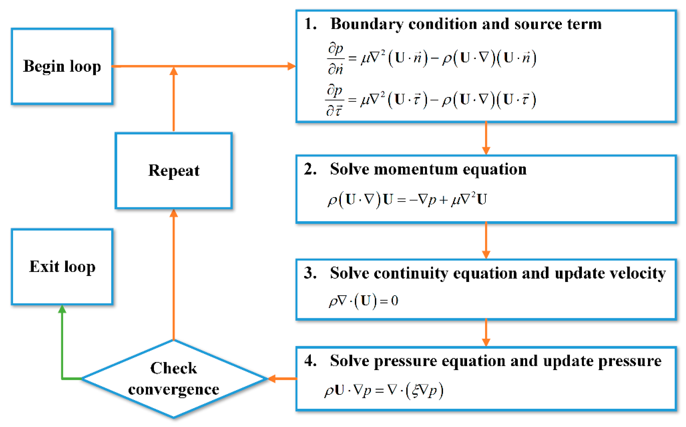
The algorithm involving both the N-S and present pressure equations is named as the pressure-velocity coupling method (PVCM for short). In this algorithm, the momentum and pressure equations are solved sequentially, in which continuity equation should be satisfied till the convergence is achieved. The detail procedure is given as shown in Figure 2.
Firstly, the initial pressure and velocity fields are estimated for the need of iteration. Secondly, the velocity and pressure are updated after the following steps: Step 1, the boundary conditions of combining the tangential and normal pressure relations are updated dynamically based on the previous pressure and velocity; Step 2, the velocity field is found by solving the N-S equation with velocity boundary conditions; Step 3, the pressure correction equation is solved to correct the velocity through guarantying the mass conservation; Step 4, the pressure field is found by solving the present pressure equation with the updated pressure boundary conditions. Then, if the calculation is converged, the present pressure and velocity fields are the final solution. Otherwise, the next iteration should start with the updated pressure and velocity till the calculation is converged. Compared to the solution of the pressure Poisson equation, obviously, the procedure mentioned above is relatively easy, which may show an application potential of the PVCM algorithm in computational fluid dynamics.

5. Results and Discussions

In order to verify the present pressure equation and pressure boundary treatment, a circular tube was selected as the physical model in the computation, and the comparison was carried out between the present PVCM and SIMPLE algorithms. As shown in Figure 3, the tube length is 1000 mm and the diameter is 20 mm. A two-dimensional computational domain is applied in the axisymmetric circular tube. The inlet velocity is uniform and the Reynolds number is 500. Thus, the velocity profile at the outlet of tube will be fully developed. The no slip velocity boundary condition is applied on the wall, and the normal velocity gradient is zero along the axis. As for the treatment of pressure boundary, it is illustrated in Figure 4 in detail. The reference pressure is zero and uniformly imposed on the outlet boundary. Firstly, the fluid pressure near the tube wall is updated with the tangential recurrence method along the tangential direction from the outlet to the inlet, and the fluid pressure near the inlet is updated from the tube wall to the axis. Then, the boundary pressure on the tube wall is updated with the normal extrapolation method. Finally, the inlet pressure is updated with linear extrapolation. By doing so, the pressure boundaries can be updated dynamically. The computational codes for pressure boundary treatment are listed in Appendix A.
The calculation program used in this work is based on the FORTRAN language. A grid system of 50 × 1000 is chosen after checking the grid independence. The grids near the tube wall are much denser than that in the core region of tube flow. The working fluid is selected as water, and the power factor ζ is 0.15 m2/s that is obtained in Ref. [40]. In addition, the power law scheme is selected to handle the diffusion-convection problem, and the discretized linear algebraic equations are solved by the alternating direction implicit method with block correction technique [41]. When relative residuals are less than 10−4, or relative residual variations are less than 1% after 1000 iterations, the numerical computation is converged. The results predicted by the SIMPLE algorithm are checked by the ANSYS FLUENT (Version 16.0, PA, USA), which also verifies the codes of present PVCM algorithm.
The velocity distributions depicted in Figure 5a are located along the central line of circular tube in the x direction. Two curves calculated by the SIMPLE and present PVCM algorithms are identical. The fluid velocity along the central line is equal to the given mean velocity 0.025 m/s at the inlet and gradually increases to 0.05 m/s when the flow is developed from the uniform velocity to the fully developed flow. The calculation results show that the fully developed velocity is two times of the inlet mean velocity, which is consistent with the theoretical predicted value, and thereby validating the present theoretical model. As for the boundary pressure on the tube wall shown in Figure 5b, it can be seen that it decreases quickly in the entrance region, which implies that the power is rapidly consumed by the fluid in this region. In the whole domain, the calculation results predicted by the present pressure equation are quite coincident with that predicted by the SIMPLE algorithm, which shows that the present pressure equation is applicable in describing the fluid flow with power consumption in the tube.
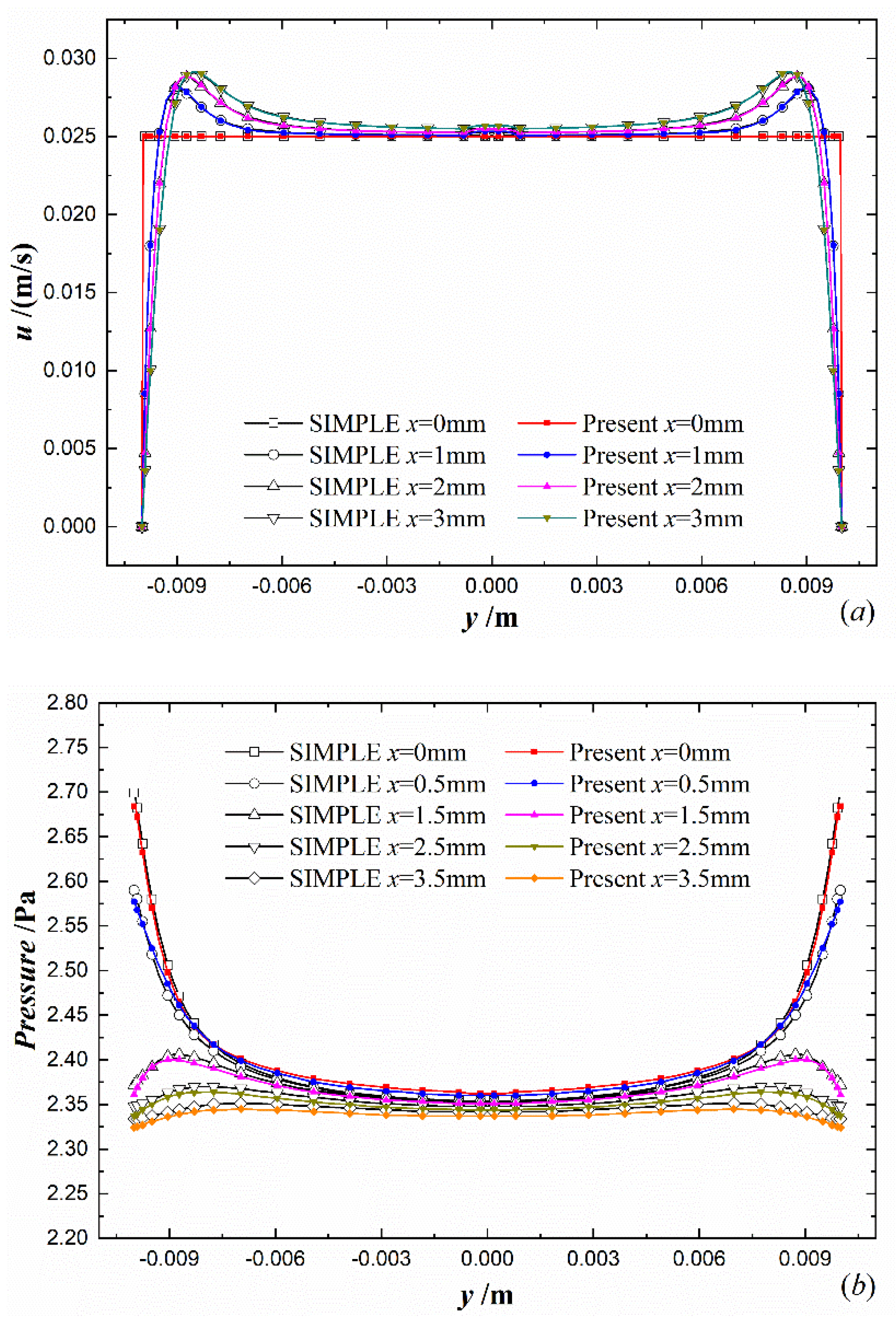
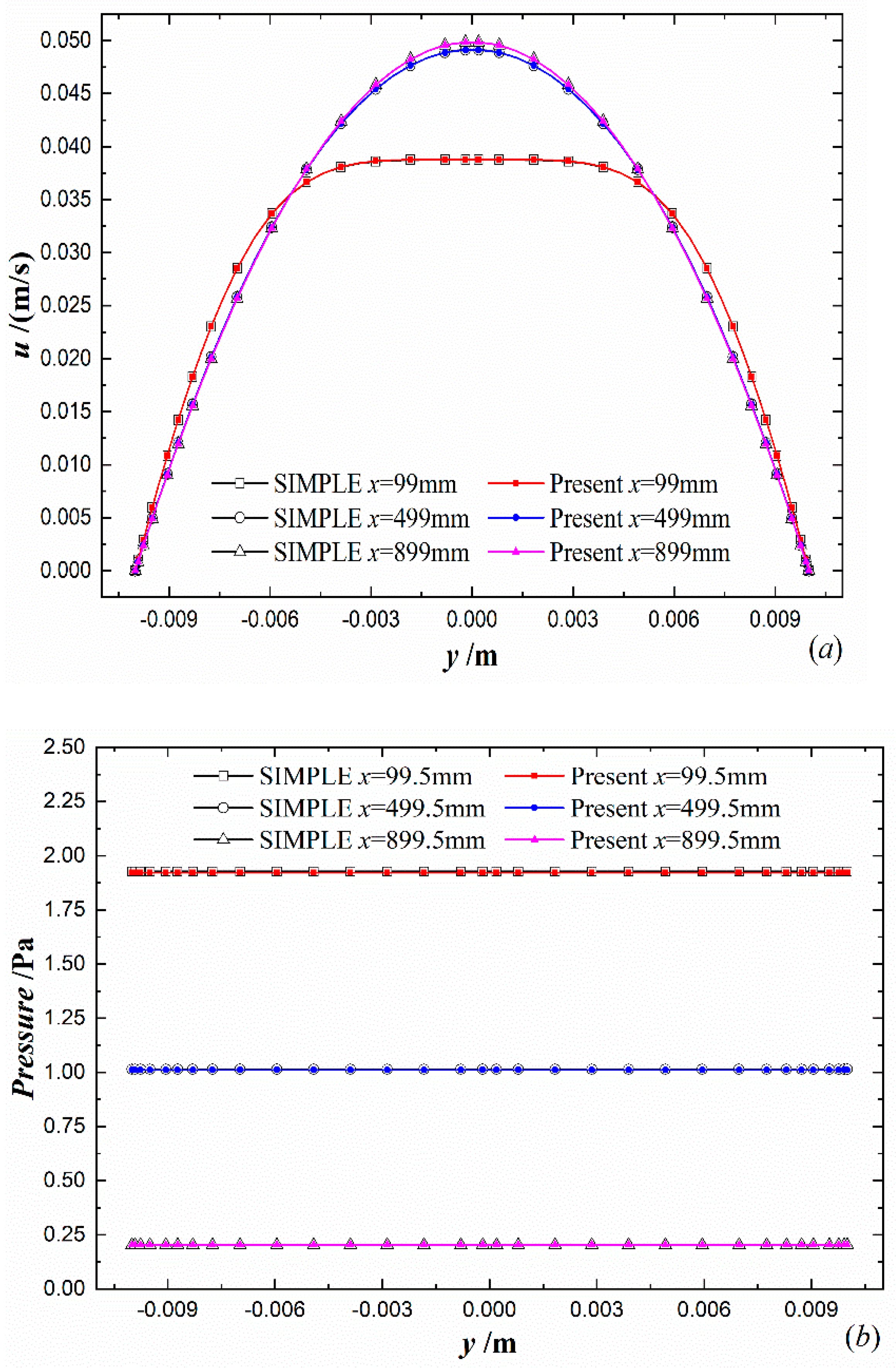
The velocity and pressure profiles in the cross section of tube perpendicular to the central axis are illustrated in Figure 6 and Figure 7. The digital numbers in the legend are distances from the inlet to those cross sections.
In the entrance region, the velocity and pressure vary greatly due to the interaction between uniform inlet velocity and no slip boundary velocity on the tube wall. In Figure 6, the comparisons of velocity and pressure are made, which locates at several columns of grids in the entrance region of the tube. For the velocity and pressure profiles in Figure 6, the results of the PVCM algorithm match well with that of the SIMPLE algorithm. As especially shown in Figure 6b, although the pressure profiles in the cross section of entrance region are nonlinear, the pressure distributions calculated by the present pressure equation are still in good agreement with the SIMPLE algorithm.
Figure 7 shows the velocity and pressure profiles at several cross section of tube. It indicates parabolic velocity distributions in the fully developed region. The results from the PVCM algorithm agree well with that of the SIMPLE algorithm both in the intermediate and fully developed regions. It verifies that the physical mechanism described by the present pressure equation is reasonable, so that this equation can be applied to solve pressure field in computational fluid dynamics.
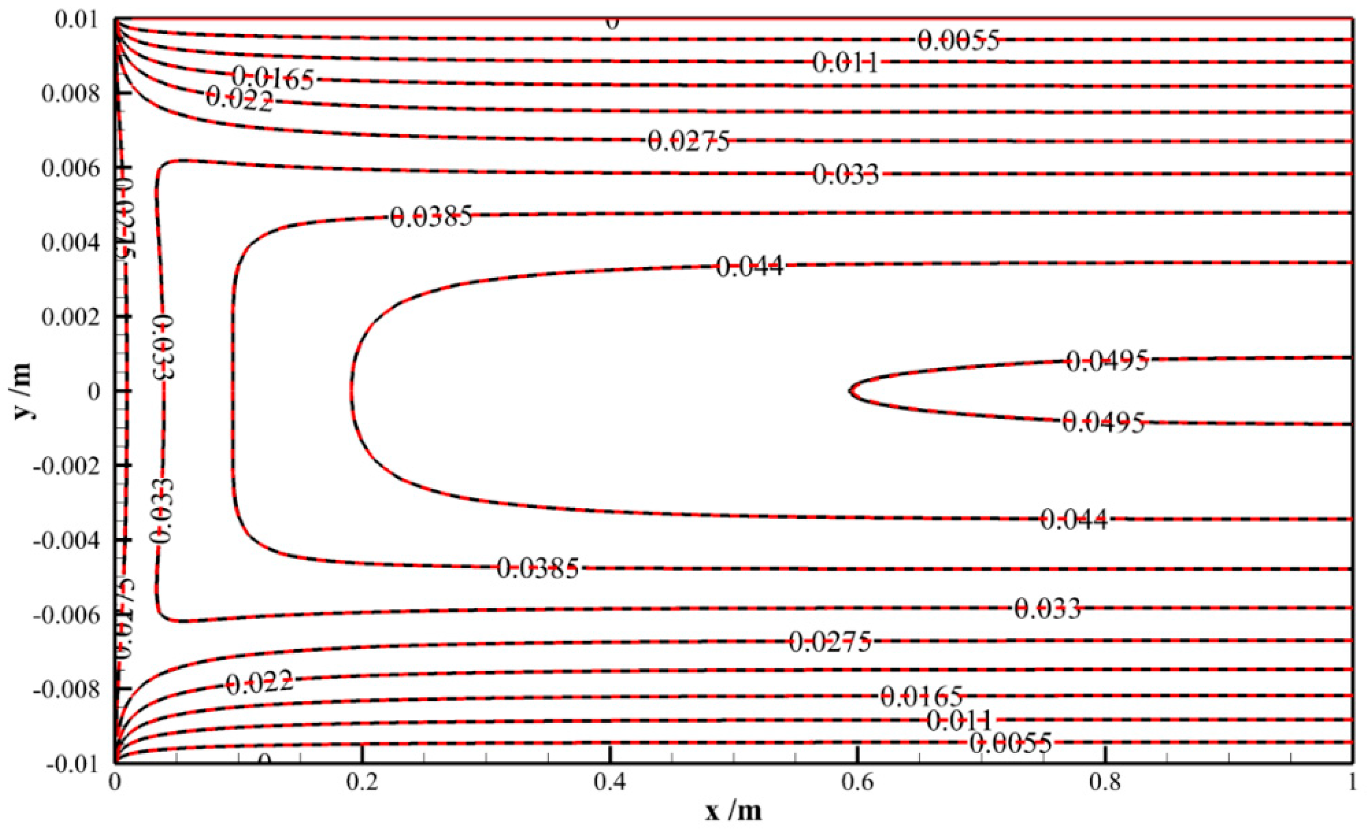
The comparison of velocity magnitude contours in the tube-axis plane, calculated by above two algorithms, is made in Figure 8. The velocity magnitude is defined as
V   =   | U |   =   u 2 + v 2 .
In Figure 8, the black dash lines represent results from the SIMPLE algorithm, and the red solid lines represent that from the PVCM algorithm. The coordinate x represents the distance in the axis direction, and the coordinate y represents the distance in the radial direction. From this figure it can be seen that the dash and solid lines entirely overlap, which indicates that the velocity field predicted by the PVCM algorithm is the same as that by the SIMPLE algorithm.
From the above analysis, it is noticed that the results calculated by the present algorithm are reliable. Therefore, the present pressure equation and its boundary conditions can be used to simulate the convection in the tube flow. In addition, the present algorithm provides a possible way of coupling the N-S equation and pressure equation, which bridges the gap between the mathematical model and a practical algorithm by solving N-S equation and pressure equation. However, the processing time of the SIMPLE algorithm is less, because the pressure equation under combined boundary conditions should be solved in the present algorithm. As for the convergence, both the SIMPLE algorithm and present algorithm are converged after 3000 iterations.

6. Conclusions

In summary, the following conclusions are made for the present study.
(1)
The transport mechanism of pressure is revealed by introducing the constitutive law and conservation equation for pressure, which have significant meaning in describing the convection of the fluid. A pressure-velocity coupling method (PVCM for short) is then proposed to solve pressure and velocity fields in the tube flow by directly coupling the present pressure equation with the N-S equation. As the conventional boundary conditions are not suitable for the pressure equation, a method of boundary treatment, which is combined by the tangential and normal direction pressure relations, was developed to deal with this problem.
(2)
In order to validate the present pressure equation with its dynamic boundary conditions investigated in this work, the numerical comparison was made between the PVCM and SIMPLE algorithms. The computational results show that the pressure and velocity solved by the two algorithms are closely consistent with each other along the central line of the circular tube, on the cross section in the entrance and fully developed regions, as well as at the tube-axis plane. The excellent agreement between them verifies that the constitutive law and conservation equation on pressure can be applied to solve pressure and velocity in the fluid flow.

Author Contributions

W.L. received the fund, proposed the idea, supervised the project, analyzed data, and revised the original draft. H.X. conducted investigation, analyzed the data and wrote the original draft. The two authors discussed the results and contributed to the preparation of the manuscript. All authors have read and agreed to the published version of the manuscript.

Funding

This work was financially supported by the National Natural Science Foundation of China (Grant No. 51736004).

Institutional Review Board Statement

Not applicable.

Informed Consent Statement

Not applicable.

Data Availability Statement

Data is contained within the present article.

Conflicts of Interest

The authors declare no conflict of interest.

Appendix A. Computational Codes for Pressure Boundary Treatment

Part 1
 DO I = 1,L1
 DO J = 1,M1
 P(I,J) = F(I,J,9)
 END DO
Part 2
/*Grid near the outlet boundary*/
 DO J = 2,M2
 I = L2
 DU(I,J) = DU(I,J)*AP(I,J)
 CON(I,J) = CON(I,J) − DU(I,J)*(P(I − 1,J) − P(I,J))
 DU(I,J) = DU(I,J)*XDIF(I)/XCVS(I)
 CON(I,J) = CON(I,J) + DU(I,J)*(P(I − 1,J) − P(L1,J))
 DU(I,J) = DU(I,J)/AP(I,J)
 END DO
/* Update the pressure along the tangential direction from (L1,M3) to (2,M3)*/
 I = L2
 J = M3
 DU(I,J) = DU(I,J)*AP(I,J)
 CON(I,J) = CON(I,J) − DU(I,J)*(P(I − 1,J) − P(L1,J))
 F(I − 1,J,9) = F(L1,J,9) + (AP(I,J)*U(I,J) − AIM(I,J)*U(I − 1,J) − AIP(I,J)*U(I + 1,J) − AJM(I,J)* U(I,J − 1) − AJP(I,J)*U(I,J + 1) − CON(I,J))/DU(I,J)
 CON(I,J) = CON(I,J) + DU(I,J)*(P(I − 1,J) − P(L1,J))
 DU(I,J) = DU(I,J)/AP(I,J)
 DO II = 4,L2
 I = L1 − II + 2
 J = M3
 DU(I,J) = DU(I,J)*AP(I,J)
 CON(I,J) = CON(I,J) − DU(I,J)*(P(I − 1,J) − P(I,J))
 F(I − 1,J,9) = F(I,J,9) + (AP(I,J)*U(I,J) − AIM(I,J)*U(I − 1,J) − AIP(I,J)*U(I + 1,J) − AJM(I,J)*U(I,J − 1) − AJP(I,J)*U(I,J + 1) − CON(I,J))/DU(I,J)
 CON(I,J) = CON(I,J) + DU(I,J)*(P(I − 1,J) − P(I,J))
 DU(I,J) = DU(I,J)/AP(I,J)
 END DO
Part 3
/* Update the pressure along the tangential direction from (3,M3) to (3,2)*/
 DO JJ = 4,M2
 J = M1 − JJ + 2
 DO I = 2,3
 DV(I,J) = DV(I,J)*AP(I,J)
 CON(I,J) = CON(I,J) − DV(I,J)*(P(I,J − 1) − P(I,J))
 F(I,J − 1,9) = F(I,J,9) + (AP(I,J)*V(I,J) − AIM(I,J)*V(I − 1,J) − AIP(I,J)*V(I + 1,J) − AJM(I,J)*V(I,J − 1) − AJP(I,J)*V(I,J + 1) − CON(I,J))/DV(I,J)
 CON(I,J) = CON(I,J) + DV(I,J)*(P(I,J − 1) − P(I,J))
 DV(I,J) = DV(I,J)/AP(I,J)
 END DO
 END DO
 F(L2,3,9) = (F(L1,3,9)*XDIF(L2) + F(L3,3,9)*XDIF(L1))/XCVS(L2)
 F(L2,M3,9) = (F(L1,M3,9)*XDIF(L2) + F(L3,M3,9)*XDIF(L1))/XCVS(L2)
/*Update the pressure for the wall and the central line */
 DO I = 2,L2
 J = 2
 F(I,1,9) = F(I,J,9)
 J = M2
 DV(I,J) = DV(I,J)*AP(I,J)
 CON(I,J) = CON(I,J) − DV(I,J)*(P(I,J − 1) − P(I,J))
 DV(I,J) = DV(I,J)*YDIF(J)/YCVRS(J)
 F(I,M1,9) = F(I,J − 1,9) − (AP(I,J)*V(I,J) − AIM(I,J)*V(I − 1,J) − AIP(I,J)*V(I + 1,J) − AJM(I,J)*V(I,J − 1) − AJP(I,J)*V(I,J + 1) − CON(I,J))/DV(I,J)
 CON(I,J) = CON(I,J) + DV(I,J)*(F(I,J − 1,9) − F(I,M1,9))
 DV(I,J) = DV(I,J)/AP(I,J)
 END DO
 F(3,M2,9) = (F(3,M3,9)*YDIF(M1) + F(3,M1,9)*YDIF(M2))/YCVS(M2)
 F(2,M2,9) = (F(2,M3,9)*YDIF(M1) + F(2,M1,9)*YDIF(M2))/YCVS(M2)
/*Update the inlet pressure with linear extrapolation*/
 DO J = 1,M1
 F(1,J,9) = (F(2,J,9)*XCVS(3) − F(3,J,9)*XDIF(2))/XDIF(3)
 END DO

References

  1. Demirel, Y. Nonequilibrium Thermodynamics: Transport and Rate Processes in Physical, Chemical and Biological Systems; Newnes: London, UK, 2013. [Google Scholar]
  2. Petschel, K.; Stellmach, S.; Wilczek, M.; Lülff, J.; Hansen, U. Dissipation Layers in Rayleigh-B\′enard Convection: A Unifying View. Phys. Rev. Lett. 2013, 110, 114502. [Google Scholar] [CrossRef] [Green Version]
  3. Calvo, I.; Sánchez, R.; Carreras, B.A.; van Milligen, B.P. Fractional Generalization of Fick’s Law: A Microscopic Approach. Phys. Rev. Lett. 2007, 99, 230603. [Google Scholar] [CrossRef] [Green Version]
  4. Chiara, N.; Drew, R.E.; Elmar, B.; Hans-Jürgen, B.; Vincent, S.J.C. Boundary slip in Newtonian liquids: A review of experimental studies. Rep. Prog. Phys. 2005, 68, 2859. [Google Scholar]
  5. Gresho, P.M.; Sani, R.L. On pressure boundary conditions for the incompressible Navier-Stokes equations. Int. J. Numer. Methods Fluids 1987, 7, 1111–1145. [Google Scholar] [CrossRef]
  6. Johnston, H.; Liu, J.-G. Accurate, stable and efficient Navier–Stokes solvers based on explicit treatment of the pressure term. J. Comput. Phys. 2004, 199, 221–259. [Google Scholar] [CrossRef]
  7. Sani, R.L.; Shen, J.; Pironneau, O.; Gresho, P. Pressure boundary condition for the time-dependent incompressible Navier–Stokes equations. Int. J. Numer. Methods Fluids 2006, 50, 673–682. [Google Scholar] [CrossRef]
  8. Liu, J. Open and traction boundary conditions for the incompressible Navier–Stokes equations. J. Comput. Phys. 2009, 228, 7250–7267. [Google Scholar] [CrossRef]
  9. Shirokoff, D.; Rosales, R.R. An efficient method for the incompressible Navier–Stokes equations on irregular domains with no-slip boundary conditions, high order up to the boundary. J. Comput. Phys. 2011, 230, 8619–8646. [Google Scholar] [CrossRef] [Green Version]
  10. Avila, K.; Moxey, D.; de Lozar, A.; Avila, M.; Barkley, D.; Hof, B. The Onset of Turbulence in Pipe Flow. Science 2011, 333, 192–196. [Google Scholar] [CrossRef] [PubMed] [Green Version]
  11. Barkley, D.; Song, B.; Mukund, V.; Lemoult, G.; Avila, M.; Hof, B. The rise of fully turbulent flow. Nature 2015, 526, 550. [Google Scholar] [CrossRef] [Green Version]
  12. Shishkina, O.; Wagner, S. Prandtl-Number Dependence of Heat Transport in Laminar Horizontal Convection. Phys. Rev. Lett. 2016, 116, 024302. [Google Scholar] [CrossRef] [PubMed]
  13. He, Y.-L.; Chu, P.; Tao, W.-Q.; Zhang, Y.-W.; Xie, T. Analysis of heat transfer and pressure drop for fin-and-tube heat exchangers with rectangular winglet-type vortex generators. Appl. Therm. Eng. 2013, 61, 770–783. [Google Scholar] [CrossRef]
  14. Chong, K.L.; Wagner, S.; Kaczorowski, M.; Shishkina, O.; Xia, K.-Q. Effect of Prandtl number on heat transport enhancement in Rayleigh-Bénard convection under geometrical confinement. Phys. Rev. Fluids 2018, 3, 013501. [Google Scholar] [CrossRef] [Green Version]
  15. Liu, P.; Zheng, N.; Shan, F.; Liu, Z.; Liu, W. An experimental and numerical study on the laminar heat transfer and flow characteristics of a circular tube fitted with multiple conical strips inserts. Int. J. Heat Mass Transf. 2018, 117, 691–709. [Google Scholar] [CrossRef]
  16. Shahzad, F.; Haq, R.U.; Al-Mdallal, Q.M. Water driven Cu nanoparticles between two concentric ducts with oscillatory pressure gradient. J. Mol. Liq. 2016, 224, 322–332. [Google Scholar] [CrossRef]
  17. Haq, R.U.; Shahzad, F.; Al-Mdallal, Q.M. MHD pulsatile flow of engine oil based carbon nanotubes between two concentric cylinders. Results Phys. 2017, 7, 57–68. [Google Scholar] [CrossRef] [Green Version]
  18. Patankar, S.V. Numerical HeatTransfer and Fluid Flow; Hemisphere: Washington, DC, USA, 1980. [Google Scholar]
  19. Van Doormaal, J.P.; Raithby, G.D. Enhancements of the Simple Method for Predicting Incompressible Fluid Flows. Numer. Heat Transf. 1984, 7, 147–163. [Google Scholar] [CrossRef]
  20. Issa, R.I.; Gosman, A.; Watkins, A. The computation of compressible and incompressible recirculating flows by a non-iterative implicit scheme. J. Comput. Phys. 1986, 62, 66–82. [Google Scholar] [CrossRef]
  21. Xiao, H.; Wang, J.; Liu, Z.; Liu, W. A consistent SIMPLE algorithm with extra explicit prediction—SIMPLEPC. Int. J. Heat Mass Transf. 2018, 120, 1255–1265. [Google Scholar] [CrossRef]
  22. Tao, W.; Qu, Z.; He, Y. A novel segregated algorithm for incompressible fluid flow and heat transfer problems—Clear (coupled and linked equations algorithm revised) part I: Mathematical formulation and solution procedure. Numer. Heat Transf. Part B Fundam. 2004, 45, 1–17. [Google Scholar]
  23. Sun, D.; Qu, Z.; He, Y.; Tao, W. An efficient segregated algorithm for incompressible fluid flow and heat transfer problems—IDEAL (inner doubly iterative efficient algorithm for linked equations) Part I: Mathematical formulation and solution procedure. Numer. Heat Transf. Part B Fundam. 2008, 53, 1–17. [Google Scholar] [CrossRef]
  24. Qu, Z.; Xu, H.; Tao, W. Numerical Simulation of Non-Equilibrium Conjugate Heat Transfer in Tubes Partially Filled with Metallic Foams. J. Therm. Sci. Technol. 2012, 7, 151–165. [Google Scholar] [CrossRef] [Green Version]
  25. Li, J.; Zhang, Q.; Zhai, Z.-Q. An efficient simpler-revised algorithm for incompressible flow with unstructured grids. Numer. Heat Transf. Part B Fundam. 2017, 71, 425–442. [Google Scholar] [CrossRef]
  26. Darwish, M.; Sraj, I.; Moukalled, F. A coupled finite volume solver for the solution of incompressible flows on unstructured grids. J. Comput. Phys. 2009, 228, 180–201. [Google Scholar] [CrossRef]
  27. Darwish, M.; Moukalled, F. A Fully Coupled Navier-Stokes Solver for Fluid Flow at All Speeds. Numer. Heat Transf. Part B Fundam. 2014, 65, 410–444. [Google Scholar] [CrossRef]
  28. Mangani, L.; Darwish, M.; Moukalled, F. An OpenFOAM pressure-based coupled CFD solver for turbulent and compressible flows in turbomachinery applications. Numer. Heat Transf. Part B Fundam. 2016, 69, 413–431. [Google Scholar] [CrossRef]
  29. Guo, Z.Y.; Li, D.Y.; Wang, B.X. A novel concept for convective heat transfer enhancement. Int. J. Heat Mass Transf. 1998, 41, 2221–2225. [Google Scholar] [CrossRef]
  30. Guo, Z.Y.; Tao, W.Q.; Shah, R.K. The field synergy (coordination) principle and its applications in enhancing single phase convective heat transfer. Int. J. Heat Mass Transf. 2005, 48, 1797–1807. [Google Scholar] [CrossRef]
  31. Tao, W.-Q.; Guo, Z.-Y.; Wang, B.-X. Field synergy principle for enhancing convective heat transfer––Its extension and numerical verifications. Int. J. Heat Mass Transf. 2002, 45, 3849–3856. [Google Scholar] [CrossRef]
  32. He, Y.L.; Tao, W.Q. Chapter Three—Convective Heat Transfer Enhancement: Mechanisms, Techniques, and Performance Evaluation. In Advances in Heat Transfer; Sparrow, E.M., Abraham, J., Gorman, J., Cho, Y., Eds.; Elsevier: Amsterdam, The Netherlands, 2014; Volume 46, pp. 87–186. [Google Scholar]
  33. Yu, Z.-Q.; Wang, P.; Zhou, W.-J.; Li, Z.-Y.; Tao, W.-Q. Study on the consistency between field synergy principle and entransy dissipation extremum principle. Int. J. Heat Mass Transf. 2018, 116, 621–634. [Google Scholar] [CrossRef]
  34. Liu, W.; Liu, Z.; Ming, T.; Guo, Z. Physical quantity synergy in laminar flow field and its application in heat transfer enhancement. Int. J. Heat Mass Transf. 2009, 52, 4669–4672. [Google Scholar]
  35. Wang, J.; Liu, W.; Liu, Z. The application of exergy destruction minimization in convective heat transfer optimization. Appl. Therm. Eng. 2015, 88, 384–390. [Google Scholar] [CrossRef]
  36. Liu, W.; Liu, P.; Wang, J.B.; Zheng, N.B.; Liu, Z.C. Exergy destruction minimization: A principle to convective heat transfer enhancement. Int. J. Heat Mass Transf. 2018, 122, 11–21. [Google Scholar] [CrossRef]
  37. Liu, W.; Liu, P.; Dong, Z.M.; Yang, K.; Liu, Z.C. A study on the multi-field synergy principle of convective heat and mass transfer enhancement. Int. J. Heat Mass Transf. 2019, 134, 722–734. [Google Scholar] [CrossRef]
  38. Chen, Q.; Wang, M.; Pan, N.; Guo, Z. Optimization principles for convective heat transfer. Energy 2009, 34, 1199–1206. [Google Scholar] [CrossRef]
  39. Liu, Y.; Chen, Q.; Hu, K.; Hao, J. Porosity distribution optimization catalyst for methanol decomposition in solar parabolic trough receiver-reactors by the variational method. Appl. Therm. Eng. 2018, 129, 1563–1572. [Google Scholar] [CrossRef]
  40. Liu, W.; Wang, J.B.; Liu, Z.C. A method of fluid dynamic analysis based on Navier-Stokes equation and conservation equation on fluid mechanical energy. Int. J. Heat Mass Transf. 2017, 109, 393–396. [Google Scholar] [CrossRef]
  41. Tao, W.Q. Numerical Heat Transfer, 2nd ed.; Xi’an Jiaotong University Press: Xi′an, China, 2001. [Google Scholar]
Figure 1. Schematic diagram of fluid domain and boundary.
Energies 14 01507 g001
Figure 2. Flow chart for pressure-velocity coupling method.
Energies 14 01507 g002
Figure 3. Schematic diagram of physical model for a tube flow.
Energies 14 01507 g003
Figure 4. Schematic diagram of pressure boundary treatment in circular tube.
Energies 14 01507 g004
Figure 5. Fluid velocity along central line (a) and boundary pressure on tube wall (b).
Energies 14 01507 g005
Figure 6. Fluid velocity (a) and pressure (b) at the cross section of entrance region.
Energies 14 01507 g006
Figure 7. Velocity (a) and pressure (b) at the cross section of tube.
Energies 14 01507 g007
Figure 8. The comparison of velocity magnitude contours in the tube-axis plane, m/s.
Energies 14 01507 g008
Publisher’s Note: MDPI stays neutral with regard to jurisdictional claims in published maps and institutional affiliations.