Article

Hybrid Reference Current Generation Theory for Solar Fed UPFC System

by
R. Senthil Kumar
1,*,
K. Mohana Sundaram
2 and
K. S. Tamilselvan
3
1
Department of Electrical and Electronics Engineering, Vel Tech High Tech Dr. Rangarajan Dr. Sakunthala Engineering College, Chennai 600062, India
2
Department of Electrical and Electronics Engineering, KPR Institute of Engineering and Technology, Coimbatore 641407, India
3
Department of Electronics and Communication Engineering, KPR Institute of Engineering and Technology, Coimbatore 641407, India
*
Author to whom correspondence should be addressed.
Energies 2021, 14(6), 1527; https://doi.org/10.3390/en14061527
Submission received: 8 February 2021 / Revised: 5 March 2021 / Accepted: 5 March 2021 / Published: 10 March 2021

Abstract

:
The extensive usage of power electronic components creates harmonics in the voltage and current, because of which, the quality of delivered power gets affected. Therefore, it is essential to improve the quality of power, as we reveal in this paper. The problems of load voltage, source current, and power factors are mitigated by utilizing the unified power flow controller (UPFC), in which a combination of series and shunt converters are combined through a DC-link capacitor. To retain the link voltage and to maximize the delivered power, a PV module is introduced with a high gain converter, named the switched clamped diode boost (SCDB) converter, in which the grey wolf optimization (GWO) algorithm is instigated for tracking the maximum power. To retain the link-voltage of the capacitor, the artificial neural network (ANN) is implemented. A proper control of UPFC is highly essential, which is achieved by the reference current generation with the aid of a hybrid algorithm. A genetic algorithm, hybridized with the radial basis function neural network (RBFNN), is utilized for the generation of a switching sequence, and the generated pulse has been given to both the series and shunt converters through the PWM generator. Thus, the source current and load voltage harmonics are mitigated with reactive power compensation, which results in attaining a unity power factor. The projected methodology is simulated by MATLAB and it is perceived that the total harmonic distortion (THD) of 0.84% is attained, with almost a unity power factor, and this is validated with FPGA Spartan 6E hardware.

1. Introduction

In commercial and domestic sectors, the usage of power electronic components have increased, which has led to end-users facing problems regarding the quality of power delivered; hence, there arises a need to solve the power quality (PQ) problems. Some of the common PQ problems, which have emerged in the distribution side and the grid side, are voltage sag/swell, harmonics, flickers, outage, etc., and all these disturbances have to be mitigated [1,2,3]. One key solution for these disturbances is the application of flexible AC transmission system (FACTS) devices, through which the quality of power has been enriched and the survey reveals the usage of various FACTS devices. Static VAR compensators (SVCs) are applied to enhance transient stability, through which the system losses are minimized. The operation of a thyristor controlled series capacitor (TCSC) is to enrich the power flow, as well as the transient and dynamic stability in the system [4], which is also applicable for subsynchronous oscillations [5]. Comparatively the static synchronous compensator (STATCOM) offers more enhanced damping characteristics than SVC, and it aids in minimizing the current harmonics. In most practical applications, voltage source inverter (VSI) with gate turn-off thyristors is the appropriate choice [6,7]. Photo voltaic (PV)-integrated STATCOMs are introduced for enriching power transmission limits and for mitigating subsynchronous oscillations; they are more economical than SVCs or regular STATCOMs [8,9]. The shunt active filter paves the way for enriching the power quality by eliminating the current harmonics, acquired by the usage of non-linear loads. Although it gives high benefits, the impact of the supply voltage affects the performance of the shunt active filter [10,11,12]. Another FACTS device, known as the dynamic voltage restorer (DVR), is employed for regulating the load voltage, by which the oscillations in the system voltage are compensated with faster dynamics. Superconducting magnetic energy storage (SMES) are incorporated with DVR, by which the compensating ability of DVR is enriched [13,14,15].
The unified power flow controller (UPFC) is one of the versatile types of FACTS devices, in which a combination of series and shunt converter are coupled through a direct current (DC) link, it aids the control of load voltage, and mitigation of source voltage harmonics are achieved. A power injection model of UPFC is designed for controlling the power system parameters, which is discussed in [16]. The transient stability of the power system is enhanced, and the power (which flows in transmission lines) is controlled by the application of UPFC. The shunt and series converters are controlled by control strategies, through which the load voltages are regulated without oscillations [17,18,19]. Generating reference signals for controlling UPFC is one of the vital parts in this work, and there exists various theories. The instantaneous reactive power theory, the synchronous reference frame theory, and the instantaneous symmetrical component theory are some of the existing theories on generating reference signals [20]. Other than this, some control algorithms are used with the application of certain filters; the non-linear adaptive filter and adaptive notch filter are included for generating the reference signal [21,22]. In this work, the genetic assisted radial basis function neural network (RBFNN) is implemented for generating the reference signal, which controls the series and shunt converters.
The integration of PV with UPFC is employed in this work, in which a high gain boost converter is essential for retaining the link voltage. An interleaved boost converter and a multi-input transformer coupled bidirectional converter has been integrated with PV, which are introduced for the reliable operation of the system [23,24,25]. While implementing PV, the main thing taken into consideration is that the output of PV should be unaffected by irradiation, which is attained by means of maximum power point tracking techniques (MPPT) techniques. The perturb and observe (P&O) method and the incremental conductance method are classical MPPT techniques, whereas the artificial neural network (ANN) and fuzzy logic control (FLC) are considered intelligent MPPT techniques. These classic and intelligent techniques have some problems when it comes to tracking performance and oscillations, which have been overcome by optimization techniques, and are adopted in this paper [26,27].
For a PV-fed UPSC, the genetic assisted RBFNN is implemented to extract the reference signal for series and shunt converters. The grey wolf optimization (GWO) technique is instigated for tracking maximum power. The switched clamped diode boost (SCDB) converter is implemented for boosting the voltage attained from PV, through which the number of solar panels is minimized. To retain the link-voltage of the capacitor, ANN is implemented. Thus, the quality of power delivered is enhanced by the proposed methodology.

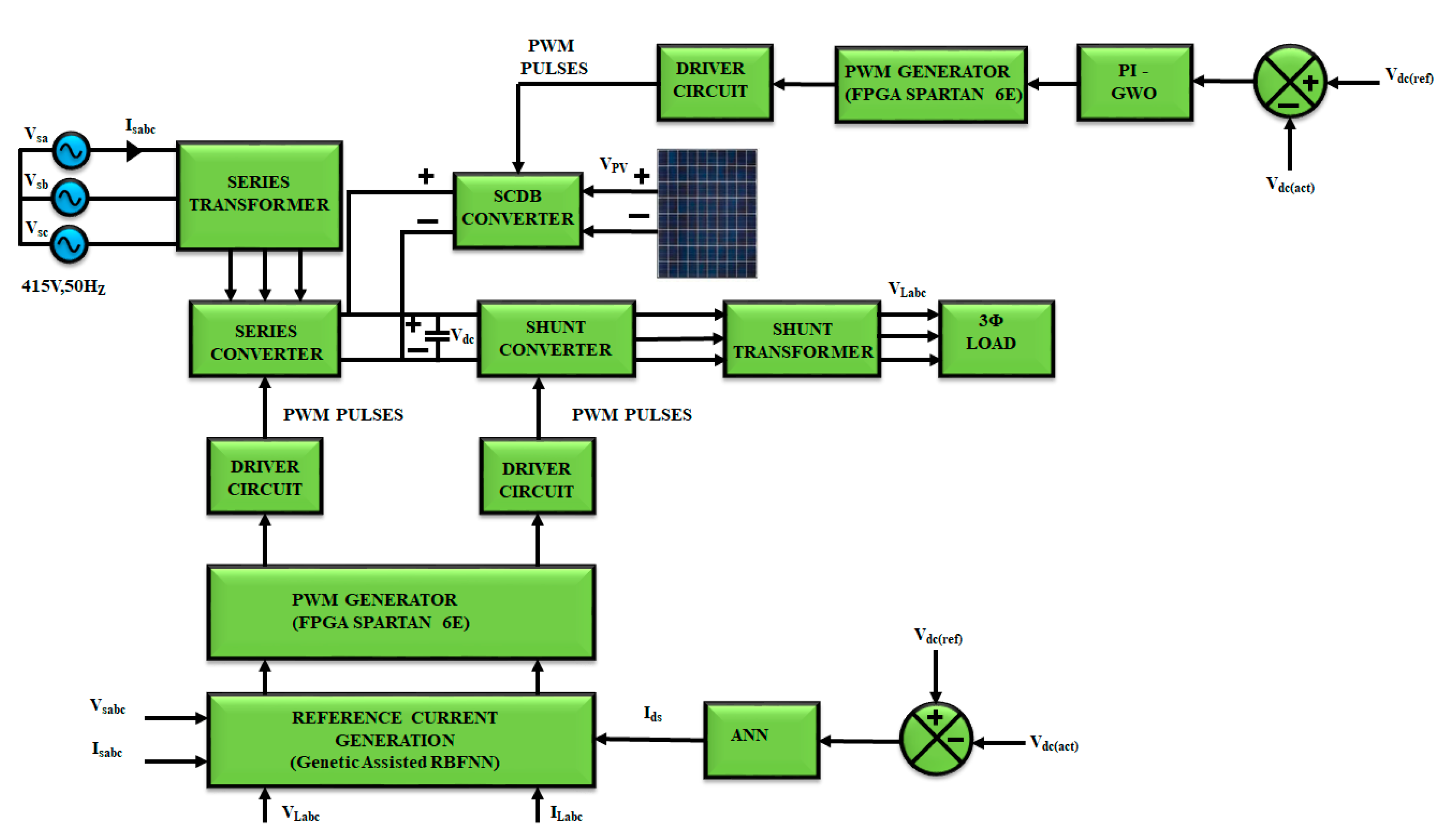
2. Proposed Control Methodology

Voltage sag/swell, harmonics, and flickers are some of the PQ disputes that arise, mainly because of the utilization of power electronic components. In order to mitigate these problems, PV-fed UPFC is utilized here; the illustration of the projected control methodology can be seen in Figure 1. UPFC comprises of a combination of series and shunt converters coupled by a DC-link, which are connected with series and shunt transformers, whereas the series converter is linked towards the source, the shunt converter is linked towards the load side.
When a three-phase AC supply is given towards a load, the AC–DC conversion occurs by means of the series converter and the energy is stored in a DC capacitor. Moreover, the power delivered to the load is reduced; hence, to overcome this, a PV system is utilized. To retain a constant PV output voltage, an SCDB converter is introduced. The link-voltage is retained by instigating proportional integral (PI)–GWO algorithm and, thus, the required gating sequence of the SCDB converter is generated. Meanwhile the output of the series converter has to be retained. The actual and reference values of Vdc are compared and fed to ANN for the reference current generation. To estimate the harmonics, which have been injected in the source current genetic assisted RBFNN, a hybrid reference current generation method is proposed. After estimating the current harmonics, the switching sequence of the shunt and the series converter are generated and, thus, an enhanced quality of power is delivered.
The modeling of the PV module, SCDB converter, GWO algorithm, UPFC, and the genetic assisted RBFNN are elaborately discussed in the upcoming sections.

3. Modeling of the Proposed Control Methodology
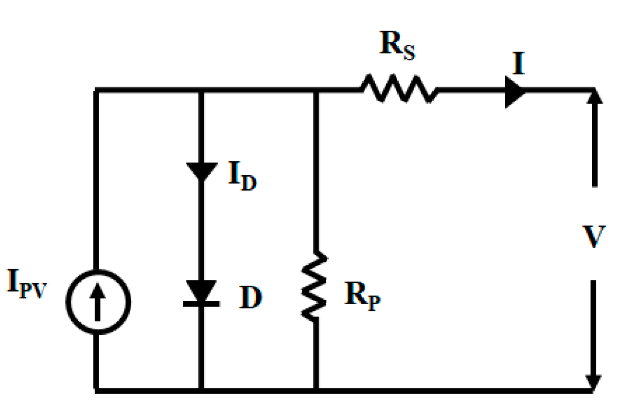
3.1. PV Module

The illustration of the PV panel is given in Figure 2. It comprises of a current source with an anti-parallel diode and two resistors, which are connected in series and in parallel, denoted as Rs and Rp, respectively.
The expression for the output current of the PV panel (for the ideal case and the real case) is given as,
I = I P V c e l l I o c e l l [ e x p q v α K T 1 ]
I = I P V I o [ e x p ( v + R s I α V k ) ] ( v + R s I ) R p
where the photovoltaic current is denoted by IPV, overload current is denoted by Io, ideality factor is denoted by α, V k k T q , and charge of the electron is denoted by q; k represents the Boltzmann constant, T represents the temperature coefficient. As there is variation in the solar irradiance, there exists variation in the current. Equation (2) can be rewritten as,
I = I P V I o [ e x p ( v + R s I ) q α k T · N s 1 ] ( v + R s I ) R p
Here, the number of the series for the PV cell is represented as Ns.

3.2. Switched Clamped Diode Boost Converter

An SCDB converter incorporated with PV is implemented because of its high gain property. The input current of this converter is continuous and the problem of the voltage spike is eliminated by this converter, which results in a constant boosted voltage. The schematic representation of the SCDB converter is shown in Figure 3. The projected converter is analyzed by its modes of operation. The simplified circuits are as illustrated in Figure 4.

3.2.1. Mode 1

This mode is referred to as the shoot-through mode, where the switch S is turned ON; at this instant, the circuit is short circuit. When D1 and D2 are OFF, L1 and L2 are charged by means of C1.

3.2.2. Mode 2

This mode is referred as the non-shoot-through mode, where D1 and D2 are ON, and the energy stored in L1 and L2 are discharged to the circuit. As a result, C1 and C2 are charged through D2, by which voltage spikes are eliminated.
The boost factor of the SCDB converter is given as the ratio of the link voltage to input voltage, which is estimated by means of relating Kirchhoff’s law for both modes of operation.
Applying Kirchhoff’s voltage law for first (shoot-through) mode,
{ V C 1 + v L 2 s h v L 1 s h = 0 v L 1 s h = v L 2 s h V C 1     ( i ) n = v L 1 v L 2 V P V + v L 3 s h V C 2 = 0 v L 3 s h = V P V + V C 2     ( i i )
Applying Kirchhoff’s voltage law for second (non-shoot-through) mode,
{ V C 1 v L 2 n o n + v L 1 n o n + V d c = 0 V P V v L 3 n o n + v L 2 n o n + V C 1 = 0 v L 3 n o n = V P V + v L 2 n o n + V C 1 v L 3 n o n = V d c V P V V C 2     ( i i i ) v L 1 n o n = V C 2 n V L 2 n o n = V C 2
The following equations are obtained after flux-balance condition through L 1 and L 2 ,
{ v L 2 s h D = v L 2 n o n ( 1 D ) v L 2 s h = V C 2 ( 1 D ) n D v L 1 s h D = v L 1 n o n ( 1 D ) V P V + v L 3 s h V C 2 v L 1 s h = V C 2 ( 1 D ) D     ( i v )
Substituting values from ( i v ) , Equation ( i ) becomes
{ v L 1 s h = v L 2 s h V C 1 V C 2 ( 1 D ) D = V C 2 ( 1 D ) n D V C 1 V C 1 = V C 2 ( n 1 ) ( 1 D ) n D     ( v )
Moreover, across L 3 , the voltage second condition is obtained as,
{ ( V P V + V C 2 ) D = ( v L 2 n o n V P V + V C 1 ) ( 1 D ) V C 2 = V P V ( n D ) n ( 1 2 D ) 1 + D     ( v i )
Substituting values from ( v i ) , Equation ( v ) becomes
V C 1 = V P V ( 1 D ) ( n 1 ) n ( 1 2 D ) 1 + D
Here, the turn’s ratio of the transformer is denoted by n, the input voltage of the converter is denoted by Vin, and the shoot-through duty cycle is denoted by D. The link voltage obtained from Equations (ii) and (iii) is as follows,
{ ( V P V + V C 2 ) D = ( V d c V P V V C 2 ) ( 1 D ) V d c = V P V ( n 1 ) n ( 1 2 D ) 1 + D
Thus, the boost factor of the proposed SCDB converter is obtained as
B = ( n 1 ) n ( 1 2 D ) 1 + D
With this boost factor, the voltage from the PV is improved. To excerpt the extreme power from PV, MPPT techniques are needed. Here, grey wolf optimization (GWO) is instigated to attain the maximum power.

3.3. GWO Algorithm

GWO algorithm is created on the leadership and chasing character of grey wolves. The wolves are categorized into four groups. Alpha (α) is the decision making wolf, which is the fittest, beta (β) is the advisor wolf for alpha, which is ranked as second, delta (δ) is considered as the third best, and omega (ω) is the lower-ranking wolf. The mathematical representation of the wolves’ hunting and encircling characters are given as,
D = | C · W p ( t ) W p ( t ) |
W ( t + 1 ) = W p ( t ) A · D
where A ,   C ,   D represents the coefficient vectors, t represents the present iteration, W p   a n d   W represents the position vector of the prey and the wolf, respectively, and the expression for the coefficient vectors are given as,
A = 2 a · r a n d 1 a
C = 2 · r a n d 2
where the random vectors are denoted by r a n d 1 and r a n d 2 , the value of a falls from 2 to 0 linearly. The number of duty ratios, V d c ( a c t ) and V d c ( r e f ) are estimated by means of the controller and, thus, the output power is computed. During a partial-shading condition, there exists several local peaks, and when the wolves catch the maximum point, their coefficient vectors reach nearly zero at that instant. By this tracking algorithm, the better tracking of maximum point is attained with minimized oscillations. Here, the duty ratio (D) is characterized as the grey wolf, and so Equation (13) can be rewritten as,
D i ( k + 1 ) = D i ( k ) A · D
The fitness function for GWO is given as
P ( d i k ) > P ( d i k 1 )
where power is denoted by P, duty cycle is denoted by d, existing number of grey wolves is denoted by i and the number of iterations is denoted by k.
The steps involved in GWO algorithm is given as,
Step 1: Set the vectors a, A and C;
Step 2: Set the number of iterations to zero (k = 0);
Step 3: Set the pack size of grey wolf as one (i = 1);
Step 4: Measure Vdc(act) by the controller;
Step 5: Compare Vdc(act) and Vdc(ref);
Step 6: If V(i) > V(i − 1), then update Vmax for i = V(i). Else update Vmax for i = V(i − 1);
Step 7: Compare Wmax and Vmax. If Wmax > Vmax, update Wmax. Or else check whether all agents are evaluated; if yes, update Wmax, A, and C by Equations (12)–(15). If not, move to (i = i + 1) and go to Step 4 until all the duty cycles are computed.
Step 8: Repeat Step 3 until convergence is met.
Thus, by GWO algorithm, the maximum power is attained and the required gating sequence for the SCDB converter is generated by means of the PWM generator-driver circuit. Thus, the DC-link voltage of the UPFC is retained.

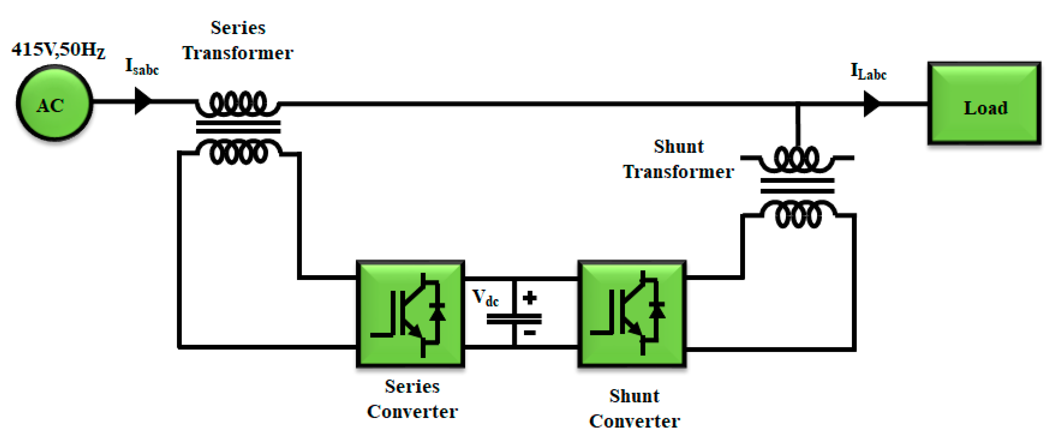
3.4. Unified Power Flow Controller

To lessen the disturbances in the power systems, the UPFC is implemented in this work, a combination of series and shunt converters coupled through a DC-link capacitor. Here, the harmonics that exist in the voltage and current are minimized by utilizing UPFC. By means of UPFC, the series, shunt, and phase angle compensation are achieved. The illustration of UPFC is shown in Figure 5.
Shunt and series converters are the chief parts of UPFC. The series converter is coupled in a series-by-series transformer by which it assists in retaining the load voltage without distortions, while the shunt converter assists in retaining the current without harmonics. The capacitor that couples the series–shunt converters helps with the proper working of both converters.

3.5. DC-Link Voltage Regulation by ANN

To develop the quality of the delivered power, the link voltage of the capacitor ( V d c ) has to be retained and these variations in the link voltage are mainly associated with the capacitor losses. Hence, a proper control is necessary, achieved by the artificial neural network (ANN). ANN works on the basis of human neural networks, which comprises three layers—input, hidden, and output layers—as illustrated in Figure 6. When an input is given to the input layer, the inputs are stored and directed to the hidden layer. The link that connects the input and the hidden layer is termed as weights. The calculations are done based on the bias given to the hidden layers and the outcome is stored in the output layer.
Here, the reference and actual values of the link voltage are given as input Levenberg–Marquardt back propagation (LMBP), instigated for generating the reference current signal. Most of the power electronics-based problems have been mitigated by ANN. If the desired criterion is not met, the error has to be computed, and the weights have to be updated to attain the desired output.
For a multi-layer perceptron, the relation of the input and output is given as
u = f ( i = 0 N 1 W i · X i ( t ) θ )
Here, the input is represented as Xi, the weighting factor is denoted as Wi, the threshold value is denoted as θ, N and f represent the number of layers and the non-linear function, respectively.
Based on the delta rule, the weighting factor is given as,
Δ p W i j = n ( t p j O p j ) i p i = n δ p j i p i
Here, n denotes the learning rate, the pth target output for jth component is denoted by tpj, pth real output for jth component is denoted by Opj, pth input for the ith component is denoted by ipi, and the error between the target and real value is denoted by δpj.
Thus, the reference d-axis current (Ids) corresponding to the DC-link voltage is generated, which is fed to the reference current generator with genetic assisted RBFNN.

3.6. Reference Current Generation by Genetic Assisted RBFNN

The control of UPFC plays a vital role in this work, which includes the control of the series converter as well as the shunt converter. A proper gating sequence is essential for the control; this is estimated by considering the load voltage, source voltage–source current, as well as the DC-link voltage. The harmonics presented in the above factors are extracted and an appropriate reference current signal is generated by means of genetic assisted RBFNN. By the genetic algorithm (GA), the solution is attained within a short time span, but the solution obtained is not optimal. Hence, hybridization of GA with RBFNN is adopted, which enhances the working of the system.

3.6.1. Genetic Algorithm
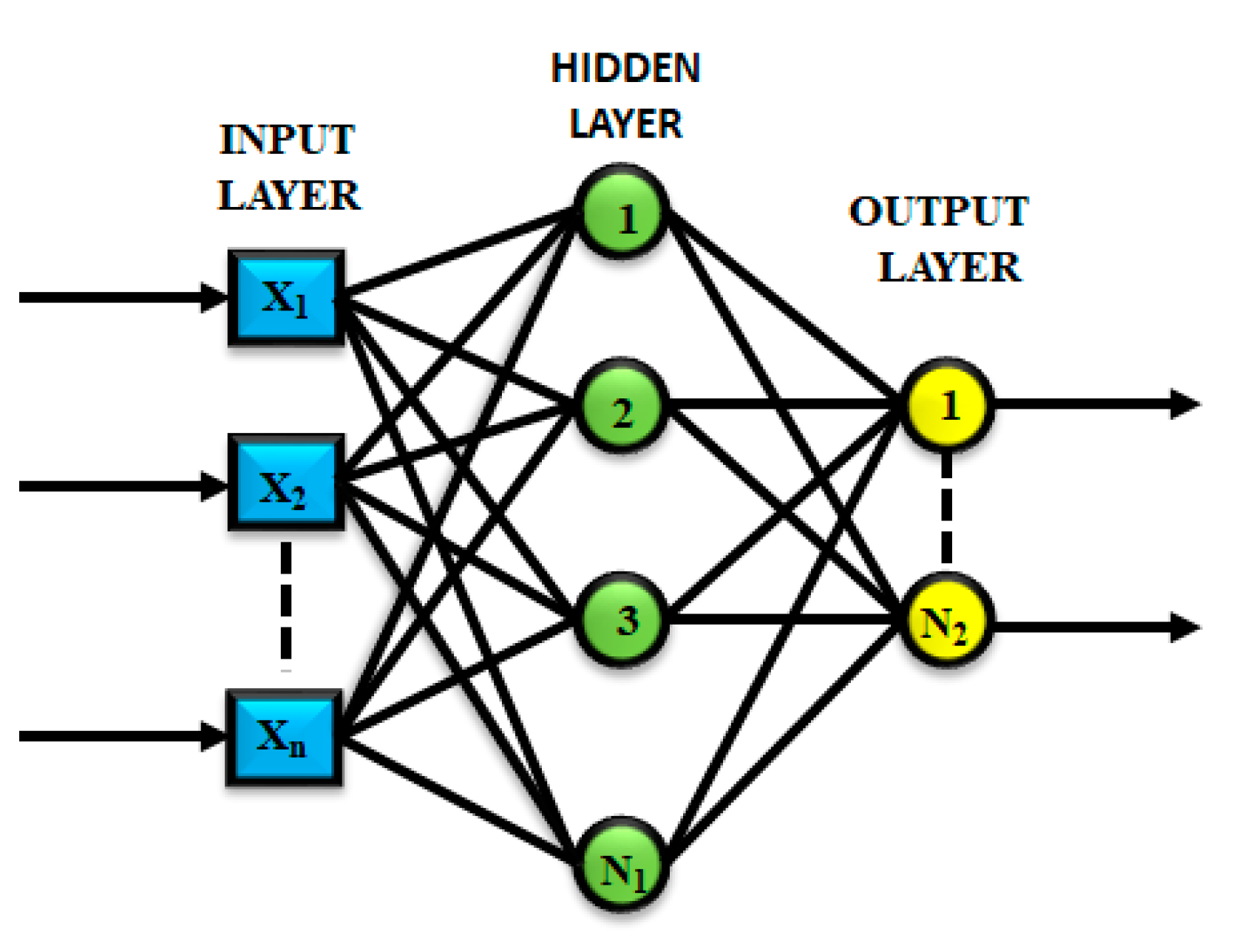
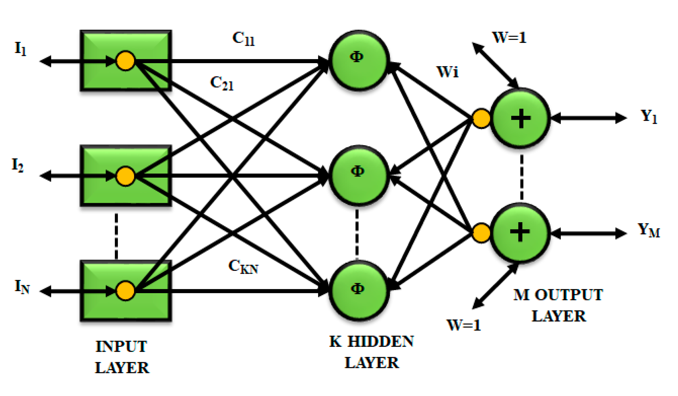
GA is an evolutionary algorithm that mimics natural genetics, in which survival of the fittest is the key point. A new population is created by selecting the chromosomes randomly through the process of mutation; the selected chromosomes are combined to form a fresh generation called strings. This newly formed generation is considered as fit as the older one. The fitness function is liable for getting the optimal solution in GA, by which the fitness values are calculated. Some of the fundamental genetic operators are crossover, reproduction, and mutation. The fitness function for GA based on RBFNN is given as,
F = C E s s m a x
where C refers to a constant, E refers the training error, the number of hidden layers is denoted by s and the maximum limit for the hidden layers is denoted by s m a x . From Equation (20), it is observed that the fitness of the chromosome is more only if the training error and the network size are least. Two-point crossover with 0.8 probability and a mutation probability is take on here.

3.6.2. RBFNN

Figure 7 represents the design of the radial basis function neural network (RBFNN) which is comprised of input layer with N number of neurons, hidden layer with K quantity of neurons, and an output layer. The input and hidden layers are coupled by means of centers, whereas the hidden and output layers are coupled by means of weights. The Gaussian basis function is given as,
Φ i ( x ) = e x p [ ( x c i ) T ( x c i ) σ i 2 ] ,   i = 1 , 2 , , K
where the data samples are represented by x , the input vector is given as ( I 1 , I 2 ,   I N ) , the center vector is denoted by C i , σ i refers the normalization factor.
The output Y i is given as,
Y i = w i T ϕ ( x ) ,   i = 1 , 2 , , M
where w i represents the output node’s weighted vector.
The weight matrix W is given as
W = A 1 ϕ T D
The desired output D for l training samples is represented as,
D = [ d ( x 1 ) d ( x j ) d ( x l ) ]
where output vector for j training samples is represented by d ( x j ) . For l training samples, the matrix ϕ is given as,
ϕ = [ ϕ 1 ( x 1 ) ϕ 2 ( x 1 ) ϕ k ( x 1 ) ϕ 1 ( x 1 ) ϕ 2 ( x 2 ) ϕ k ( x 2 ) ϕ 1 ( x l ) ϕ 2 ( x l ) ϕ k ( x l ) ]
The expression for variance matrix is given as,
A 1 = ( ϕ T ϕ ) 1
The network structure of RBFNN comprises of an input signal with one neuron, a hidden layer with 500 neurons, the magnitude of the harmonics present in the source and load waveforms are minimized by the k-means clustering algorithm.

3.6.3. Genetic Assisted RBFNN

When compared to the other neural network models, RBFNN is chosen for its simplicity as it requires only one hidden layer, and the learning rate and the activation function can be varied. The main part of this is to eliminate the harmonic content and to generate the reference signal. Figure 8 shows the working of genetic assisted RBFNN.
The following are the steps involved in genetic assisted RBFNN:
  • Based on the quantity of neurons at the hidden layer, the RBFNN is initialized. The center of the bias function is attained from k-means clustering and the center width is estimated by
    σ = d 2 s
    where the width of the Gaussian function is represented by σ , center is denoted by s , the alteration among actual and reference values is termed as spacing and is denoted by d .
  • Set the population size, process of selection, operators of crossover and mutation, and number of repetitions.
  • Initialize the population as P with size N.
  • RBFNN is constructed by means of the training samples; the output error e of the network is computed by,
    e = k = 1 n ( t k y k ) 2
  • The fitness of the chromosome is calculated by Equation (20).
  • Based on the fitness evaluated, the chromosomes are arranged, and the ideal population fitness ( F P ) is computed. If e < e m i n or generation G G m a x , go to Step 9 or go to next step.
  • For the next generation, some optimum individuals are selected and reserved.
  • Select a pair of chromosomes to perform crossover operation, through which a new generation is formed with four individuals. Repeat this process until the population reaches the maximum.
  • Change the population number in the new generation and, thus, a new population is created. Now, set population as new population and G = G + 1 . Go to Step 4.
  • Get the perfect neural network layout. The final working of GA ends, which shows that the optimization is finished.
Thus, the genetic assisted RBFNN is employed for the generation of reference current, by which the reference current signal is created and the required switching sequence of UPFC is generated by means of the PWM generator-driver circuit setup. Through this, the existed variations in the load voltage and source voltage-current are minimized and the quality of power delivered is enhanced.

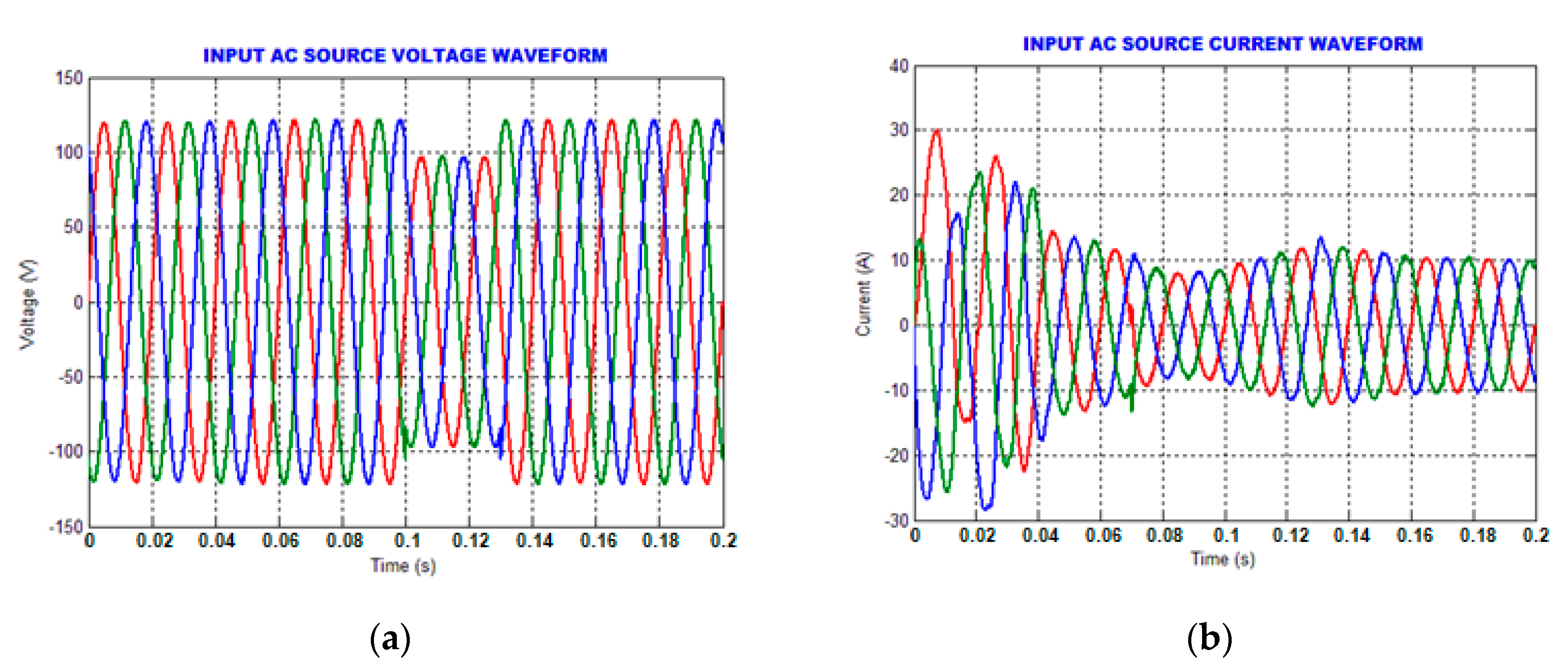
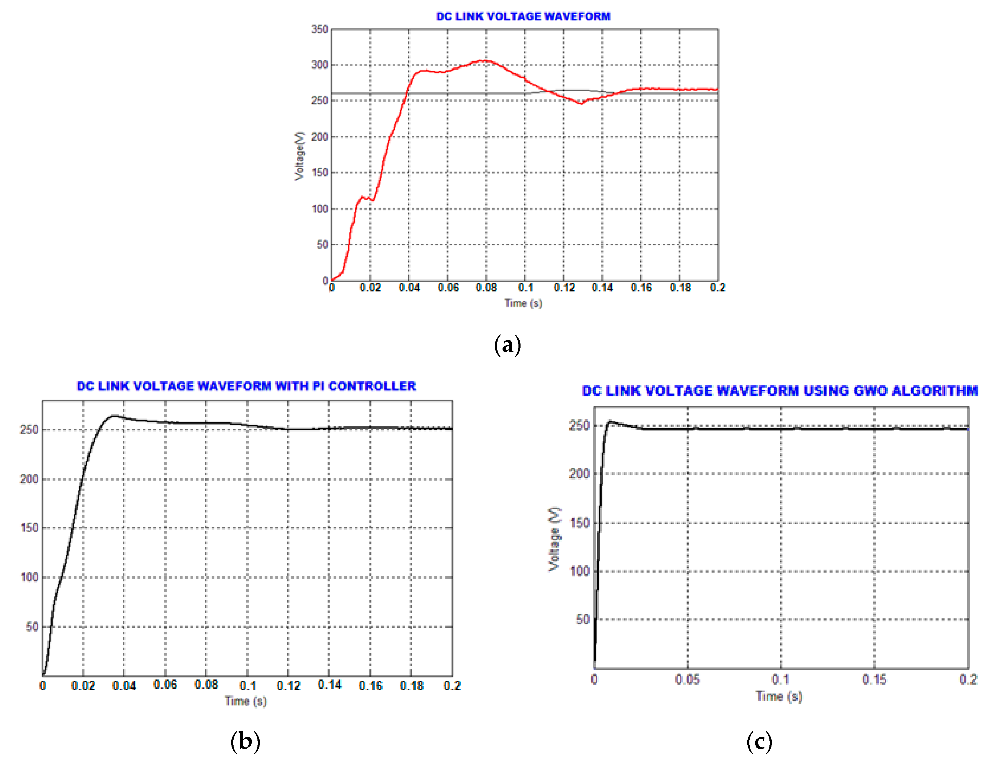
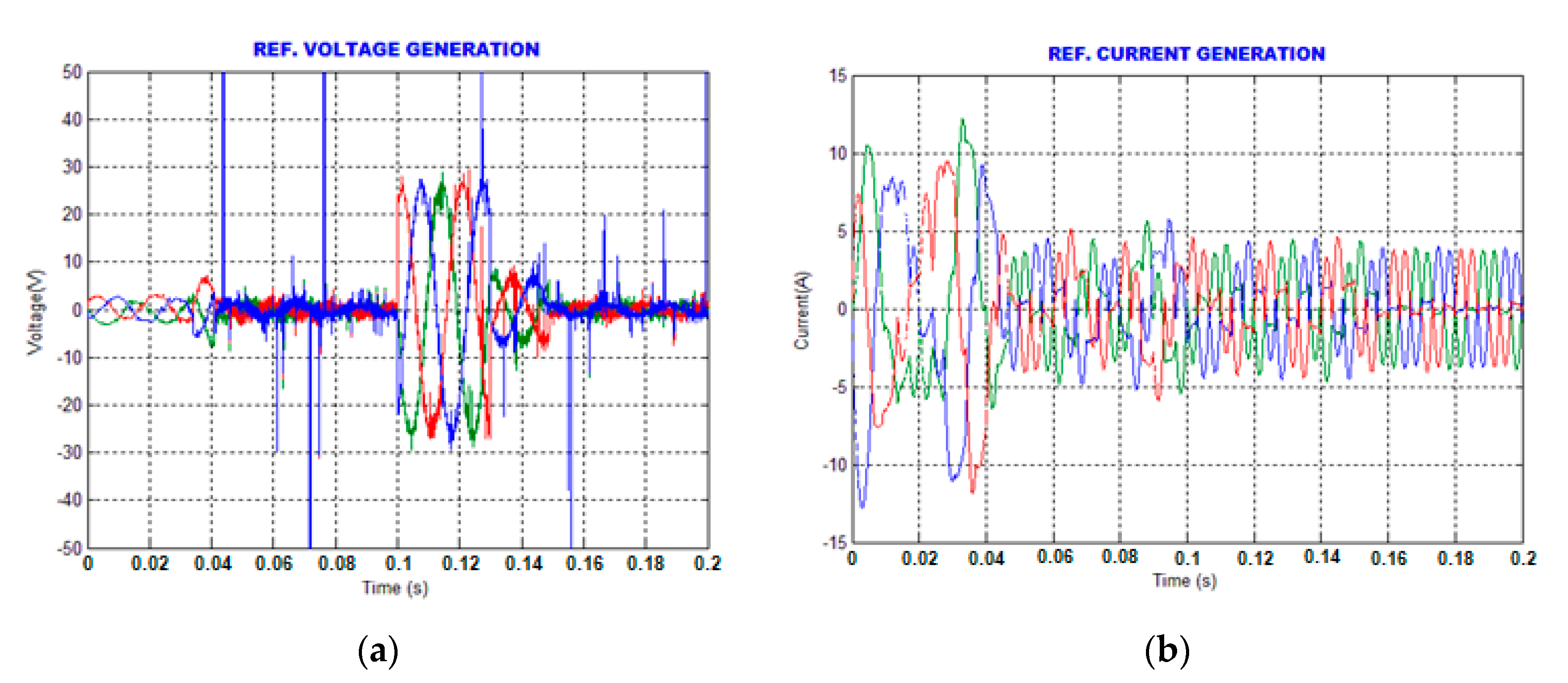
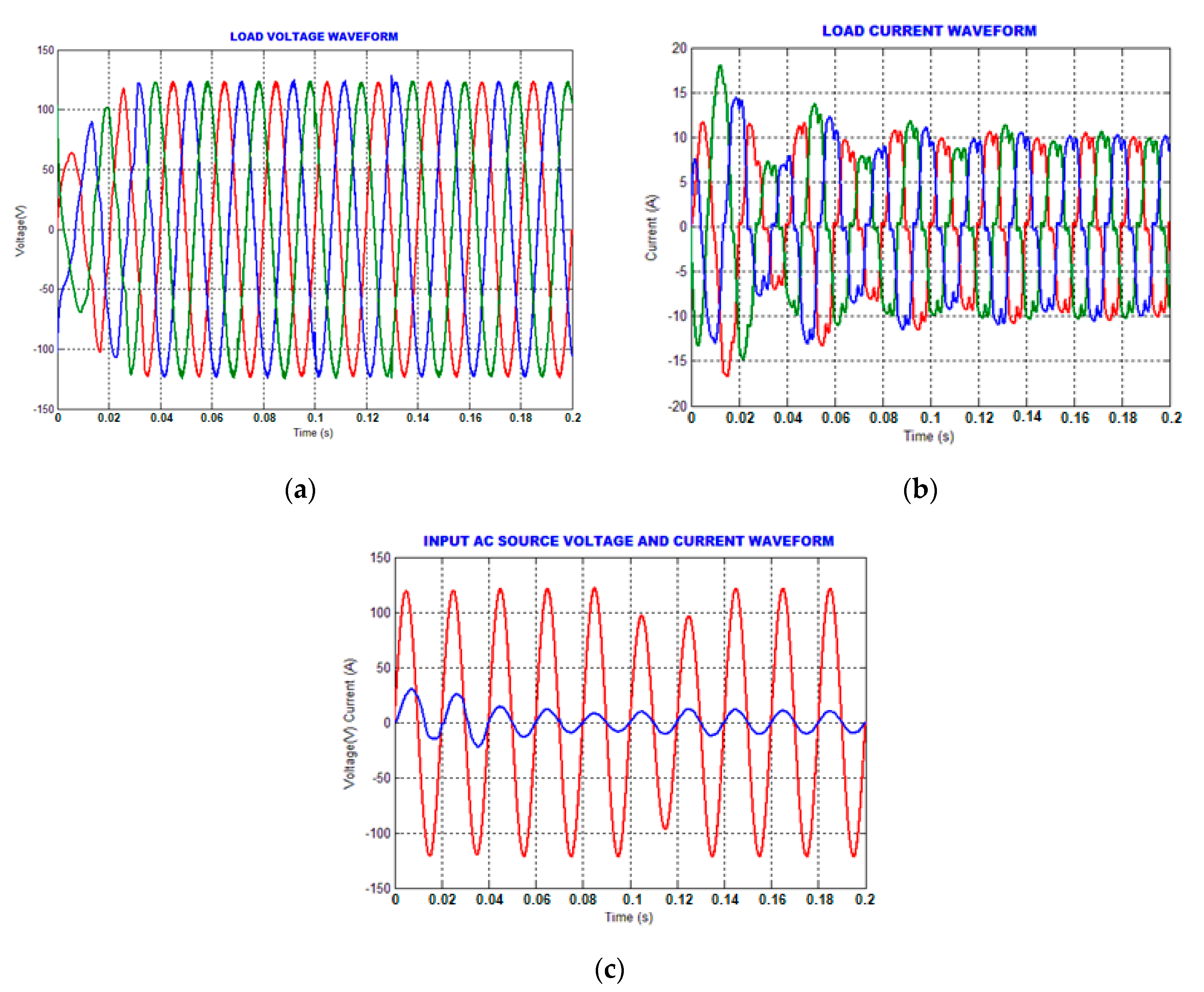
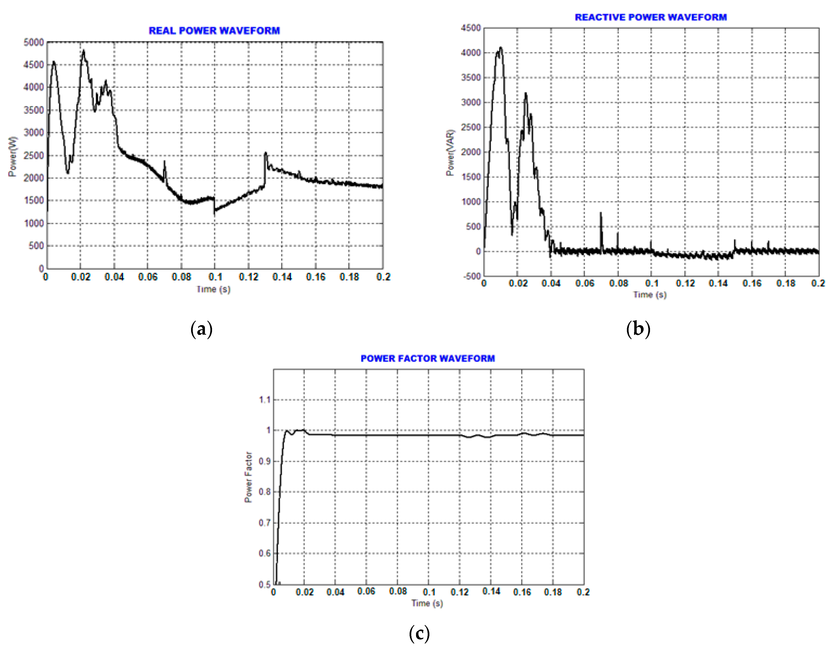
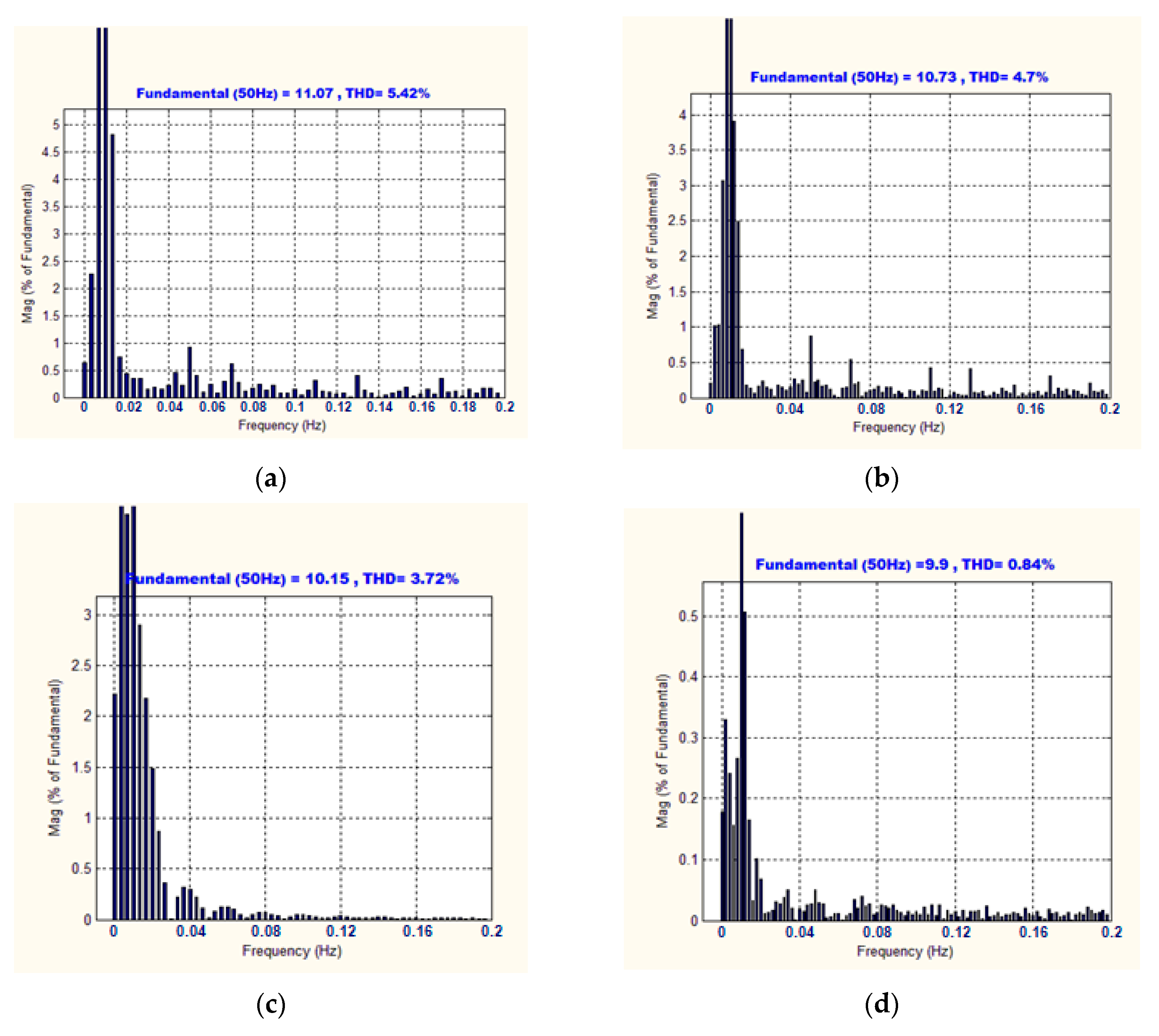
4. Results and Discussion

In today’s emerging technology, there arises a necessity to mitigate power quality problems. The problems, such as load voltage, source current, and power factor are analyzed in this study. Enhancing the quality of power is achieved by utilizing UPFC, which includes series and shunt converters that are interconnected by a DC-link capacitor; which assists in storing energy when connected to the supply. The capacitor stores energy through the grid during the nighttime, whereas in the daytime, the PV module is utilized. The high gain SCDB converter is applied to boost the voltage, through which the number of solar panels is reduced and the maximum power is attained by the GWO algorithm. When the AC supply is given through the grid for UPFC, there exists harmonics in the system parameters. Hence, a reference current generation scheme is necessary by which the harmonics that occur in the load voltage and source current are minimized. Here the genetic assisted RBFNN is implemented for generating the reference current and, thus, the required pulses of UPFC is attained with the aid of a PWM generator. Similarly, the link voltage of the capacitor is retained by ANN. Thus, the harmonics in the load voltage and source current are reduced to a greater extent with unity power factor. This proposed methodology is executed at MATLAB and simulation results are obtained. The solar panel of a 10 KW power rating is chosen, and the SCDB converter’s specification is given in Table 1.
Figure 9 depicts the waveforms of the source voltage and source current. To analyze the proper functioning of UPFC with the proposed methodology, a voltage sag problem is created in the duration 0.1 to 0.14 s. A voltage sag in this time interval is mentioned through a voltage waveform in Figure 9a, whereas the variation in the current is mentioned through the current waveform in Figure 9b
Figure 10 illustrates the link-voltage of the capacitor, with the utilization of a PV module being utilized, i.e., during daytime and without a controller, the link-voltage is perceived, which is highlighted in Figure 10a. Figure 10b,c demonstrates the link-voltage waveform of the PI controller and with the proposed GWO, respectively, for the SCDB converter. It is perceived that, with the PI controller, the waveform settles around 0.12 s, and after the implementation of GWO, the link voltage starts to settles earlier, at around 0.05 s. Figure 11a,b depicts the reference voltage and current, respectively.
Figure 12a,b depicts the waveforms of load voltage and load current. From the load voltage waveform, it is perceived that, even though there exists voltage sag problems in the source voltage, the load voltage shows no variations other than a little spike. Figure 12c demonstrates the waveforms of the source voltage and source current; it is perceived that both are in-phase.
The waveforms of real power and reactive power, which are developed for a 2 KW system, are illustrated in Figure 13a,b correspondingly. The real power, which is taken from the grid, is high and retained in the initial stage, i.e., before compensation. The reactive power observed is almost zero. Figure 13c depicts the power factor waveform, which implies that the power factor of 0.999 is achieved, through which the stability of the system is enriched.
The source current THD is depicted in Figure 14. Figure 14a shows the THD with the PI controller alone. It is observed that 5.42% and 4.7% THD is attained with fuzzy, as shown in Figure 14b. The source current THD is also observed with ANN before and after incorporating genetic assisted RBFNN, as depicted in Figure 14c,d, respectively, and the THD of the proposed methodology is observed as 0.84%.

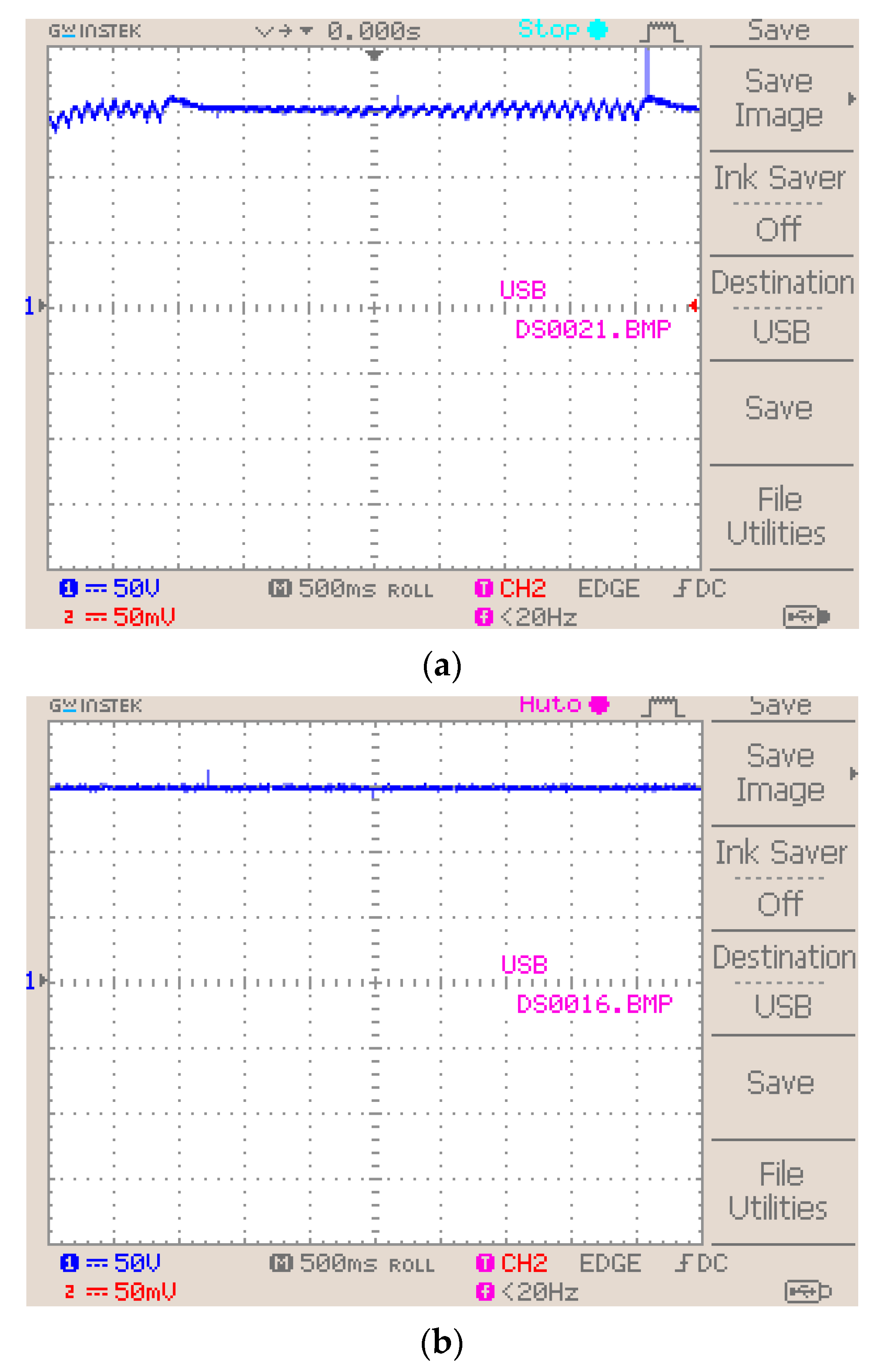
Hardware Implementation

The proposed control methodology is also implemented in hardware by FPGA Spartan 6E, in which the problems of load voltage, source current, and power factor are mitigated. Figure 15 shows the input voltage waveform; this shows variations in the amplitude. The PV panel’s voltage waveform is depicted in Figure 16.
Figure 17a,b depict the link-voltage of the capacitor with the PI controller and with the GWO algorithm, respectively. It is observed that the peak overshoot problem occurred in PI, and the response took too long to settle, but with GWO, these problems are eliminated and the link-voltage of the capacitor is retained.
The source voltage and source current representation is depicted in Figure 18, and it is perceived that the voltage and current are in-phase. The the input voltage waveform in Figure 15 shows amplitude variations, but the load voltage waveform in Figure 19 shows that the voltage is constant.
A comparison of source current THD (Figure 20) is carried out and the proposed methodology is compared with conventional PI and fuzzy. The THD values, which are, respectively, 5.42% and 4.7%. With ANN before implementation of GA–RBFNN, the THD is found to be 3.72%, and it is observed that after implementation of genetic assisted RBFNN along with ANN it possess a low THD value, of 0.84%.

5. Conclusions

One of the emerging challenges a power system faces is the mitigation of power quality issues. Among which, compensation of load voltage, source current, and power factor are taken into account; the UPSC is utilized to mitigate these problems. Series and shunt converters are the major parts of UPSC, which are coupled through a DC- link capacitor. In order to attain maximum power, a PV module is implemented by a high-gain SCDB converter incorporated with GWO. Reference current generation is the vital part in which genetic assisted RBFNN is implemented, and the gating sequence of the series and the shunt converters are generated; moreover, ANN is instigated for retaining the DC-link voltage. The simulation result shows that the projected methodology is effective for compensation of load voltage and source current. Furthermore, a power factor of 0.999 and a source current THD of 0.84% have been achieved with a minimum settling time. The simulation and hardware outcomes show the control methodology proposed is more efficient.

Author Contributions

Conceptualization, R.S.K.; methodology, R.S.K.; software, R.S.K. and K.M.S.; validation, R.S.K. and K.M.S.; formal analysis, R.S.K.; investigation, R.S.K.; resources, R.S.K.; data curation, R.S.K.; writing—original draft preparation, R.S.K. and K.M.S.; writing—review and editing, R.S.K. and K.S.T.; visualization, R.S.K.; supervision, K.M.S. and K.S.T.; project administration, K.M.S. and K.S.T.; funding acquisition, R.S.K. All authors have read and agreed to the published version of the manuscript.

Funding

This research received no external funding.

Institutional Review Board Statement

Not applicable.

Informed Consent Statement

Not applicable.

Data Availability Statement

Data is contained within the article.

Conflicts of Interest

The authors declare no conflict of interest.

References

  1. Barros, J.; De Apráiz, M.; Diego, R.I. Power Quality in DC Distribution Networks. Energies 2019, 12, 848. [Google Scholar] [CrossRef] [Green Version]
  2. Reid, W.E. Power quality issues-standards and guidelines. IEEE Trans. Ind. Appl. 1996, 32, 625–632. [Google Scholar] [CrossRef]
  3. González de la Rosa, J.-J.; Donsión, M.P. Analysis for Power Quality Monitoring. Energies 2020, 13, 514. [Google Scholar] [CrossRef] [Green Version]
  4. Abas, N.; Dilshad, S.; Khalid, A.; Saleem, M.S.; Khan, N. Power Quality Improvement Using Dynamic Voltage Restorer. IEEE Access 2020, 8, 164325–164339. [Google Scholar] [CrossRef]
  5. Gandomana, F.H.; Ahmadib, A.; Sharafc, A.M.; Sianod, P.; Poub, J.; Hredzakb, B.; Agelidise, V.G. Review of FACTS technologies and applications for power quality in smart grids with renewable energy systems. Elsevier Renew. Sustain. Energy Rev. 2018, 82, 502–514. [Google Scholar] [CrossRef]
  6. Popavath, L.N.; Kaliannan, P. Photovoltaic-STATCOM with Low Voltage Ride through Strategy and Power Quality Enhancement in a Grid Integrated Wind-PV System. Energies 2018, 7, 51. [Google Scholar] [CrossRef] [Green Version]
  7. Pilotto, L.A.S.; Bianco, A.; Long, W.F.; Edris, A.A. Impact of TCSC control methodologies on subsynchronous oscillations. IEEE Trans. Power Deliv. 2003, 18, 243–252. [Google Scholar] [CrossRef]
  8. Varma, R.K.; Rahman, S.A.; Vanderheide, T. New Control of PV Solar Farm as STATCOM (PV-STATCOM) for Increasing Grid Power Transmission Limits during Night and Day. IEEE Trans. Power Deliv. 2015, 30, 755–763. [Google Scholar] [CrossRef]
  9. Liang, Y.; Nwankpa, C.O. A new type of STATCOM based on cascading voltage-source inverters with phase-shifted unipolar SPWM. IEEE Trans. Ind. Appl. 1999, 35, 1118–1123. [Google Scholar] [CrossRef]
  10. Rao, P.; Crow, M.L.; Yang, Z. STATCOM control for power system voltage control applications. IEEE Trans. Power Deliv. 2000, 15, 1311–1317. [Google Scholar] [CrossRef] [Green Version]
  11. Tsang, K.M.; Chan, W.L. Design of single-phase active power filter using analogue cascade controller. Ieee Proc. Electr. Power Appl. 2006, 153, 735–741. [Google Scholar] [CrossRef]
  12. Carlos, G.A.D.; Jacobina, C.B.; Méllo, J.P.R.A.; Santos, E.C. A Shunt Active Power Filter Based on Cascaded Transformers Coupled With Three-Phase Bridge Converters. IEEE Trans. Ind. Appl. 2017, 53, 4673–4681. [Google Scholar] [CrossRef]
  13. Longhui, W.; Fang, Z.; Pengbo, Z.; Hongyu, L.; Zhaoan, W. Study on the Influence of Supply-Voltage Fluctuation on Shunt Active Power Filter. IEEE Trans. Power Deliv. 2007, 22, 1743–1749. [Google Scholar] [CrossRef]
  14. Shi, J.; Tang, Y.; Yang, K.; Ren, L.C.; Li, J.; Cheng, S. SMES Based Dynamic Voltage Restorer for Voltage Fluctuations Compensation. IEEE Trans. Appl. Supercond. 2010, 20, 1360–1364. [Google Scholar]
  15. Torres, A.P.; Sánchez, P.R.; Batlle, V.F. A Two Degrees of Freedom Resonant Control Scheme for Voltage-Sag Compensation in Dynamic Voltage Restorers. IEEE Trans. Power Electron. 2018, 33, 4852–4867. [Google Scholar] [CrossRef]
  16. Liu, J.Y.; Song, Y.H.; Mehta, P.A. Strategies for handling UPFC constraints in steady-state power flow and voltage control. IEEE Trans. Power Syst. 2000, 15, 566–571. [Google Scholar]
  17. Yang, S.; Liu, Y.; Wang, X.; Gunasekaran, D.; Karki, U.; Peng, F.Z. Modulation and Control of Transformerless UPFC. IEEE Trans. Power Electron. 2016, 31, 1050–1063. [Google Scholar] [CrossRef]
  18. Haque, M.M.; Ali, M.S.; Wolfs, P.; Blaabjerg, F. A UPFC for Voltage Regulation in LV Distribution Feeders With a DC-Link Ripple Voltage Suppression Technique. IEEE Trans. Ind. Appl. 2020, 56, 6857–6870. [Google Scholar] [CrossRef]
  19. Gholipour, E.; Saadate, S. Improving of transient stability of power systems using UPFC. IEEE Trans. Power Deliv. 2005, 20, 1677–1682. [Google Scholar] [CrossRef]
  20. Singh, B.; Solanki, J. A Comparison of Control Algorithms for DSTATCOM. IEEE Trans. Ind. Electron. 2009, 56, 2738–2745. [Google Scholar] [CrossRef]
  21. Singh, B.; Jain, C.; Goel, S.; Chandra, A.; Haddad, K.A. A Multifunctional Grid-Tied Solar Energy Conversion System With ANF-Based Control Approach. IEEE Trans. Ind. Appl. 2016, 52, 3663–3672. [Google Scholar] [CrossRef]
  22. Teke, A.; Saribulut, L.; Tumay, M. A Novel Reference Signal Generation Method for Power-Quality Improvement of Unified Power-Quality Conditioner. IEEE Trans. Power Deliv. 2011, 26, 2205–2214. [Google Scholar] [CrossRef]
  23. Aghdam, F.H.; Abapour, M. Reliability and Cost Analysis of Multistage Boost Converters Connected to PV Panels. IEEE J. Photovolt. 2016, 6, 981–989. [Google Scholar] [CrossRef]
  24. Mangu, B.; Akshatha, S.; Suryanarayana, D.; Fernandes, B.G. Grid-Connected PV-Wind-Battery-Based Multi-Input Transformer-Coupled Bidirectional DC-DC Converter for Household Applications. IEEE J. Emerg. Sel. Top. Power Electron. 2016, 4, 1086–1095. [Google Scholar] [CrossRef]
  25. Kardan, F.; Alizadeh, R.; Banaei, M.R. A New Three Input DC/DC Converter for Hybrid PV/FC/Battery Applications. IEEE J. Emerg. Sel. Top. Power Electron. 2017, 5, 1771–1778. [Google Scholar] [CrossRef]
  26. Brito, M.A.G.; Galotto, L.; Sampaio, L.P.; Melo, G.A.; Canesin, C.A. Evaluation of the Main MPPT Techniques for Photovoltaic Applications. IEEE Trans. Ind. Electron. 2013, 60, 1156–1167. [Google Scholar] [CrossRef]
  27. Bollipo, R.B.; Mikkili, S.; Bonthagorla, P.K. Critical Review on PV MPPT Techniques: Classical, Intelligent and Optimisation. IET Renew. Power Gener. 2020, 14, 1433–1452. [Google Scholar] [CrossRef]
Figure 1. Proposed control methodology.
Energies 14 01527 g001
Figure 2. Photo voltaic (PV) panel–equivalent circuit.
Energies 14 01527 g002
Figure 3. Proposed switched clamped diode boost (SCDB) converter.
Energies 14 01527 g003
Figure 4. Operating modes of the SCDB converter.
Energies 14 01527 g004
Figure 5. Representation of UPFC.
Energies 14 01527 g005
Figure 6. Artificial neural network (ANN) topology.
Energies 14 01527 g006
Figure 7. Topology of radial basis function neural network (RBFNN).
Energies 14 01527 g007
Figure 8. Working of genetic assisted RBFNN.
Energies 14 01527 g008
Figure 9. (a) Source voltage waveform (b) Source current waveform.
Energies 14 01527 g009
Figure 10. (a) DC-link voltage; (b) DC-link voltage with PI controller; (c) proposed SCDB converter output.
Energies 14 01527 g010
Figure 11. Waveform for (a) reference voltage (b) reference current.
Energies 14 01527 g011
Figure 12. Waveforms for (a) load voltage; (b) load current; (c) source voltage and source current.
Energies 14 01527 g012
Figure 13. Illustration of (a) real power; (b) reactive power; (c) power factor.
Energies 14 01527 g013
Figure 14. Source current THD with (a) PI (b) Fuzzy (c) ANN without genetic algorithm (GA)–RBFNN (d) ANN incorporated with GA–RBFNN.
Energies 14 01527 g014
Figure 15. Input voltage waveform.
Energies 14 01527 g015
Figure 16. PV panel voltage.
Energies 14 01527 g016
Figure 17. (a) Link-voltage with PI controller; (b) link-voltage with grey wolf optimization (GWO).
Energies 14 01527 g017
Figure 18. Source voltage and source current.
Energies 14 01527 g018
Figure 19. Load voltage waveform.
Energies 14 01527 g019
Figure 20. Comparison of source current THD.
Energies 14 01527 g020
Table 1. Parameters of SCDB converter.
ParametersValues
L1200 µH
L2130 µH
L3100 µH
C1 = C2100 µF
Switching frequency10 KHz
Publisher’s Note: MDPI stays neutral with regard to jurisdictional claims in published maps and institutional affiliations.

