Article

Development of Three-Phase Permanent-Magnet Synchronous Motor Drive with Strategy to Suppress Harmonic Current

Department of Electrical Engineering, National Taiwan University of Science and Technology, Taipei 106, Taiwan
*
Author to whom correspondence should be addressed.
Energies 2021, 14(6), 1583; https://doi.org/10.3390/en14061583
Submission received: 30 January 2021 / Revised: 7 March 2021 / Accepted: 9 March 2021 / Published: 12 March 2021
(This article belongs to the Special Issue Design and Control of Electrical Motor Drives)

Abstract

:
This study aimed to develop a three-phase permanent-magnet synchronous motor drive system with improvement in current harmonics. Considering the harmonic components in the induced electromotive force of a permanent-magnet synchronous motor, the offline response of the induced electromotive force (EMF) was measured for fast Fourier analysis, the main harmonic components were obtained, and the voltage required to reduce the current harmonic components in the corresponding direct (d-axis) and quadrature (q-axis) axes was calculated. In the closed-loop control of the direct axis and quadrature axis current in the rotor reference frame, the compensation amount of the induced EMF with harmonic components was added. Compared with the online adjustment of current harmonic injection, this simplifies the control strategy. The drive system used a 32-bit digital signal processor (DSP) TMS320F28069 as the control core, the control strategies were implemented in software, and a resolver with a resolver-to-digital converter (RDC) was used for the feedback of angular position and speed. The actual measurement results of the current harmonic improvement control show that the total harmonic distortion of the three-phase current was reduced from 5.30% to 2.31%, and the electromagnetic torque ripple was reduced from 15.28% to 5.98%. The actual measurement results verify the feasibility of this method.

1. Introduction

The induced electromotive force of a permanent-magnet motor may contain harmonic components because of the design, which produces electromagnetic torque ripples after multiplying with the phase current of the motor (which also contains harmonic components) [1,2]. Therefore, reducing the harmonic components of the motor current provides a reduction in torque ripples. By performing the harmonic analysis of the current to obtain the harmonic components contained and then adding them to the current command, the influence of the current on the torque can be reduced [3,4]. To reduce the current ripple due to the induced EMF, the harmonic components of the induced EMF can be analyzed and injected into the voltage command, as shown in [5]. Most methods add the harmonic components of the induced EMF to the three-phase voltage command. The compensation parameters of current or induced EMF are based on the analysis of its harmonic components. It is known that the three-phase signals containing harmonics can be transformed into the rotating rotor reference frame and projected on the 0-axis, direct axis (d-axis), and quadrature axis (q-axis) [6]. With open-end windings and driven each phase current independently, the zero-sequence harmonics of the induced EMF are added to the 0-axis voltage command directly, in conjunction with field-oriented control (FOC) can reduce current harmonics [7]. Torque ripple can be estimated from the calculated energy and co-energy through the voltage and current feedback, which is used as the feed-forward compensation amount to reduce the torque ripple and current ripple component [8]. Recently, different control methods have been applied to reduce current harmonics or torque ripple. By using the Kalman filter, the stator current and permanent-magnet (PM) rotor flux are used to track the flux linkage and compensate for the torque ripple caused by the demagnetization [9]. Artificial neural networks are used to reduce the torque ripple of the permanent-magnet synchronous motor (PMSM) with non-sinusoidal induced EMF and cogging torque [10]. Predictive torque control is also used to reduce torque ripple and improve its control accuracy by compensating for the current prediction errors [11]. Selective current harmonic suppression method is proposed to reduce current harmonics in case of high-speed operation [12].
In this study, the methods presented in [13,14] were used to conduct fast Fourier transform (FFT) analysis of induced EMF. The induced EMF of the fifth and seventh harmonic components was obtained, the contents and offset angles of which were further analyzed. Moreover, the rotor’s rotating coordinate system was used to obtain the sixth harmonic component in direct axis and quadrature axis. Compensation was applied to the q-axis and the d-axis to reduce current harmonic components and torque ripple. Compared with the techniques mentioned above, the method proposed in this paper requires less computational burden and does not need to change the control scheme; however, it is necessary to measure the induced EMF of the motor and analyze its harmonic components as the reference of compensation.
In this paper, Section 2 introduces the mathematical model of the permanent-magnet synchronous motor considering the fifth and seventh harmonics; Section 3 proposes a control strategy to reduce torque ripple with two methods of compensation for abc or qd coordinate systems; Section 4 first measures the induced EMF of the permanent-magnet synchronous motor and determines the compensation amount by spectrum analysis, and compares the current spectrum and torque ripple components with different control strategies.

2. Current and Torque Ripples of Permanent-Magnet Synchronous Motors

If the salience effect is neglected and the d-axis and q-axis inductances are the same, the voltages of a three-phase permanent-magnet synchronous motor can be expressed as follows:
ν a = R s i a + L s d d t i a + e a f ,
ν b = R s i b + L s d d t i b + e b f ,
ν c = R s i c + L s d d t i c + e c f ,
where v a , v b , and v c are the input phase voltages of the motor; i a , i b , and i c are the three-phase stator currents; R s is the equivalent resistance and L s is the equivalent inductance of the stator; e a f , e b f , and e c f are the three-phase induced EMF of the motor. Due to the symmetry of the rotor, the induced EMF contains no even harmonic components. For the motor with the Y connection, the zero-sequence harmonics can be neglected as they are coupled to both ends of each phase [15]. Therefore, only the odd harmonics of the positive and negative sequences need to be considered.
The matrix for transforming the three-phase system to the rotor reference frame and its inverse transformation is as follows:
T q d r = 2 3 [ cos θ ^ r cos ( θ ^ r 120 ) cos ( θ ^ r + 120 ) sin θ ^ r sin ( θ ^ r 120 ) sin ( θ ^ r + 120 ) ] ,
T q d r 1 = [ cos θ r sin θ r cos ( θ r 120 ) sin ( θ r 120 ) cos ( θ r + 120 ) sin ( θ r + 120 ) ] .
Under balanced conditions, the three-phase motor uses the transformation matrix T q d r of the rotor reference frame, and the voltages of the q-axis and the d-axis are:
v q r = R s i q r + L q d d t i q r + ω r ( λ m + L d i d r ) ,
v d r = R s i d r + L d d d t i d r ω r L q i q r ,
where v q r and v d r are the input voltages; i q r and i d r are the currents of the q-axis and d-axis, respectively.
The three-phase permanent-magnet synchronous motor used in this study mostly contains the fifth and seventh harmonic components, and the other harmonics barely exist. Therefore, the fifth and seventh harmonic components were added to the estimated values in this section. The resultant induced EMF estimates e ^ a , e ^ b , and e ^ c are:
e ^ a = ω ^ r λ m cos θ ^ r + h 5 ω ^ r λ m cos [ 5 ( θ ^ r + δ 5 5 ) ] + h 7 ω ^ r λ m cos [ 7 ( θ ^ r + δ 7 7 ) ] ,
e ^ b = ω ^ r λ m cos ( θ ^ r 120 ° ) + h 5 ω ^ r λ m cos [ 5 ( θ ^ r + δ 5 5 120 ° ) ] + h 7 ω ^ r λ m cos [ 7 ( θ ^ r + δ 7 7 120 ° ) ] ,
e ^ c = ω ^ r λ m cos ( θ ^ r + 120 ° ) + h 5 ω ^ r λ m cos [ 5 ( θ ^ r + δ 5 5 + 120 ° ) ] + h 7 ω ^ r λ m cos [ 7 ( θ ^ r + δ 7 7 + 120 ° ) ] ,
where E ^ m = ω ^ r λ m is the estimated value of the peak induced EMF; h 5 and h 7 are the percentages of the fifth and seventh harmonic components of the induced EMF; δ 5 and δ 7 are the phase differences between the fifth and seventh harmonics and the fundamental wave of the induced EMF, respectively.
Using the transformation matrix T q d r of the rotor’s synchronous rotating coordinate system, the induced EMF containing the fifth and seventh harmonic components is transformed into components along the q-axis and d-axis, e ^ q r and e ^ d r , respectively, expressed as:
e ^ q r = ω ^ r λ m + h 5 ω ^ r λ m cos ( 6 θ ^ r + δ 5 ) + h 7 ω ^ r λ m cos ( 6 θ ^ r + δ 7 ) = ω ^ r λ m +   h 6 q ω ^ r λ m cos ( 6 θ ^ r + δ 6 q ) ,
e ^ d r = h 5 ω ^ r λ m sin ( 6 θ ^ r + δ 5 ) h 7 ω ^ r λ m sin ( 6 θ ^ r + δ 7 ) = h 6 d ω ^ r λ m sin ( 6 θ ^ r + δ 6 d ) ,
where the harmonics of the induced EMF along the q-axis and d-axis, e ^ q h r and e ^ d h r , respectively, are expressed as:
e ^ q h r = h 6 q ω ^ r λ m cos ( 6 θ ^ r + δ 6 q ) ,
e ^ d h r = h 6 d ω ^ r λ m sin ( 6 θ ^ r + δ 6 d ) .
It can be seen from Equations (11) and (12) that, when the fifth and seventh harmonic components of the induced EMF are transformed into the rotor reference frame and further simplified by the polar coordinate system, they will contain the sixth harmonic components. Therefore, the sixth harmonic components can be used for compensation in the rotor reference frame. In the equations above: h 6 q is the coefficient indicating the percentage of the sixth harmonic component along the q-axis; δ 6 q is the phase difference between the sixth harmonic and the fundamental wave along the q-axis; h 6 d is the coefficient indicating the percentage of the sixth harmonic component along the d-axis; δ 6 d is the phase difference between the sixth harmonic component and the fundamental wave along the d-axis.

3. Current Harmonic Improvement Strategy for Closed-Loop Control of Current along q-Axis and d-Axis

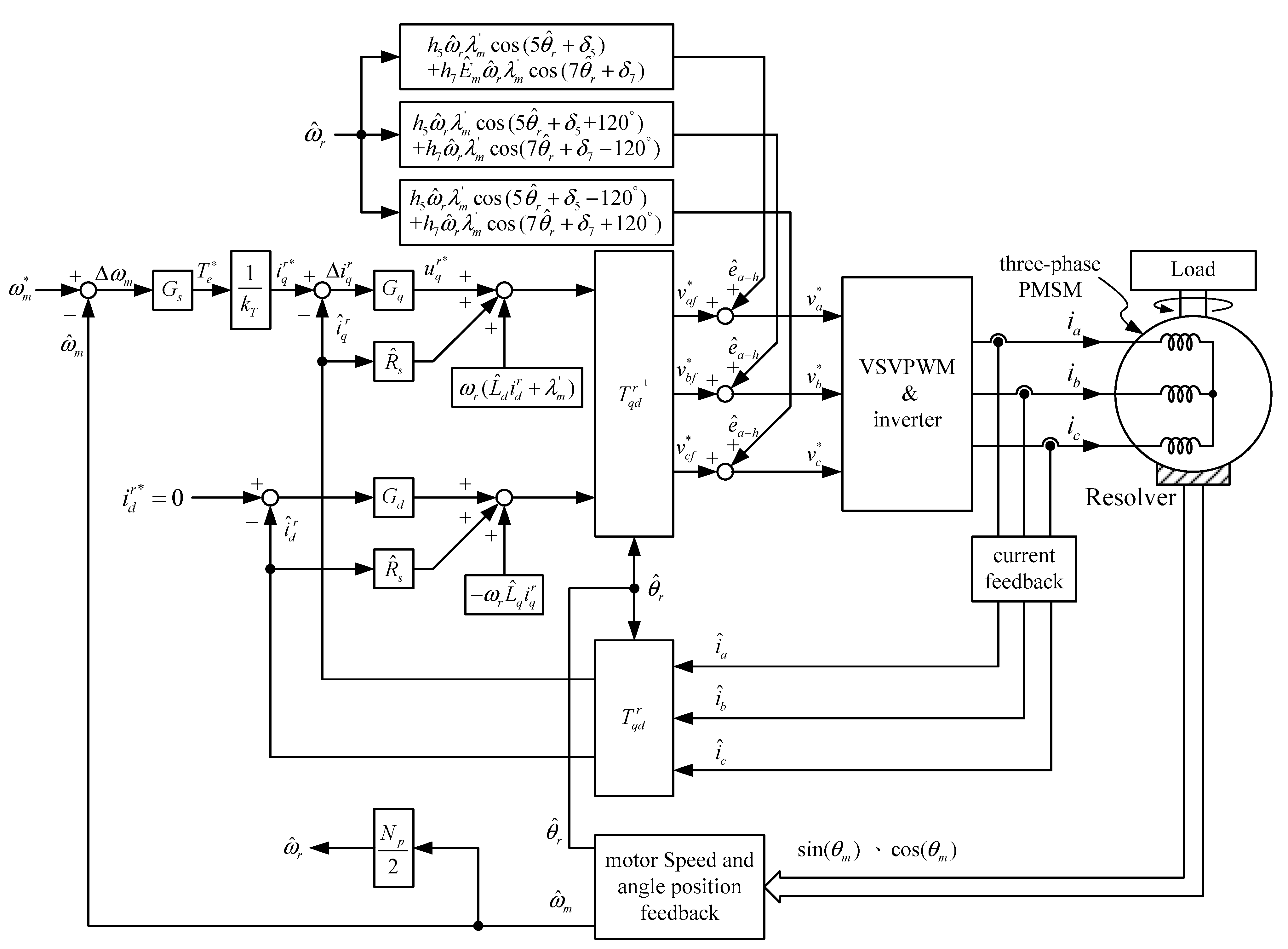
3.1. Closed-Loop Control Strategy for q-Axis and d-Axis Currents with Compensation for Fundamental Wave of Induced EMF

The closed-loop control of the speed and the q-axis and d-axis currents of the three-phase permanent-magnet synchronous motor in this study are shown in Figure 1. The speed feedback ω ^ m and position feedback θ ^ r in Figure 1 are obtained from the the resolver and RDC. The three-phase feedback currents i ^ a , i ^ b , and i ^ c of the motor are transformed to the rotor reference frame to obtain the q-axis current i ^ q r and the d-axis current i ^ d r . Moreover, the q-axis and d-axis current control strategy is used to obtain the q-axis and d-axis voltage commands v q r * and v d r * . Finally, the inverse transformation matrix of the rotor reference frame is used to obtain the three-phase voltage commands v a , v b * , and v c * , and then feed to the space vector pulse width modulation (SVPWM) module to produce the switching signals.
The closed-loop control block of the q-axis and d-axis currents is shown in Figure 1. The three-phase sinusoidal signal without the harmonic components is transformed into two direct current (DC) signals, direct axis and quadrature axis signals respectively in the rotor reference frame. The transformation of the rotor reference frame can reduce the influence of external disturbance and improve the robustness of the control strategy. The q-axis and d-axis current regulator of the synchronous motor can be obtained according to voltage Equations (6) and (7). By reducing the coupling terms ω r ( L d i d r + λ m ) and ω r L q i q r in voltage Equations (6) and (7), the linearized voltages u q r and u d r along the q-axis and d-axis are defined as, respectively:
u q r = R s i q r + L q d d t i q r = v q r ω r ( L d i d r + λ m ) ,
u d r = R s i d r + L d d d t i d r = v d r + ω r L q i q r ,
Decoupling u q r and i q r in Equation (15), and u d r and i d r in Equation (16), independent linear systems can be obtained, and the q-axis and d-axis current regulator outputs are, respectively:
u q r * = G q ( i q r * i ^ q r ) ,
u d r * = G d ( i d r * i ^ d r ) ,
where i q r * and i d r * are the q-axis and d-axis current commands. The current regulators G q and G d are both proportional-integral controllers with “ ” as the symbol of proportional-integral operation. The transfer function of the current regulator is expressed as
G q = k p q + k i q s ,
G d = k p d + k i d s ,
where k p q and k p d are the proportional gain; k i q and k i d are the integral gain. The q-axis and d-axis voltage commands v q r * and v d r * can be expressed as
v q r * = u q r * + R ^ s i ^ q r + ω r ( L ^ d i ^ d r + λ ^ m ) ,
v d r * = u d r * + R ^ s i ^ d r ω r L ^ q i ^ q r ,
The pre-computed feed-forward compensation R s i q r and R s i d r can be added into the q-axis and d-axis voltage commands, respectively, to increase system response speed.

3.2. Compensation Method of Induced EMF Harmonics along Phase-a, Phase-b, and Phase-c

The compensation strategy along the a-axis, b-axis, and c-axis is based on the speed and the q-axis and d-axis current closed-loop control strategy shown in Figure 1, with additional compensation for the fifth and seventh harmonic components of the three-phase induced EMF, as shown in Figure 2. As the induced EMF compensation in Figure 1 contains only that for the fundamental wave, the fifth and seventh harmonic components of the induced EMF are not compensated. After transforming the q-axis and d-axis voltage commands v q r * and v d r * with the rotor’s synchronous reference system, compensation for the fifth and seventh harmonic components of the induced EMF along the a-axis, b-axis, and c-axis are added, as shown in Figure 2.

3.3. Compensation Method of Induced EMF Harmonics along q-Axis and d-Axis

The fifth and seventh harmonic components of the induced EMF are mapped to the sixth harmonic component after transformed to the rotor reference frame, as shown in Figure 3. By compensating on the qd-axis, the calculation of the control strategy can be simplified. The compensation strategy for harmonics in the induced EMF along the q-axis and d-axis adds the sixth harmonic component in Figure 1, as shown in Equations (13) and (14). By adding Equations (13) and (14) into Figure 1 as the compensation, the resulting control block is as shown in Figure 3. The software was developed based on Figure 3.

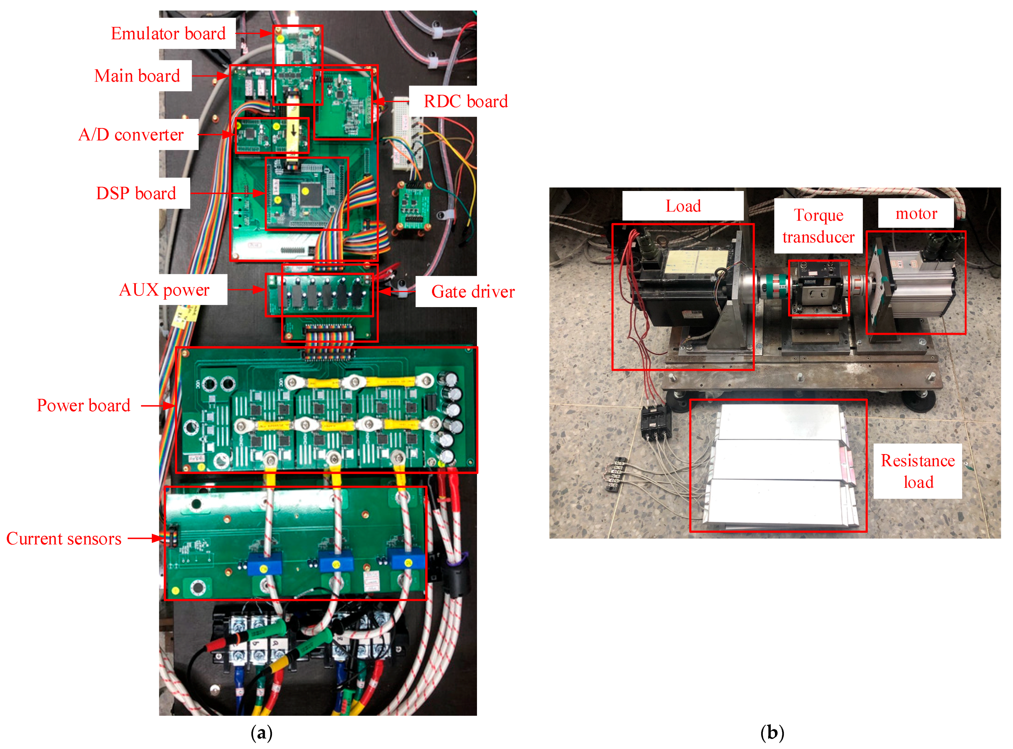
4. Measurement Results

A laboratory prototype based on DSP TMS320F28069 is established to verify the proposed method. The photograph of the motor driver and testbed is shown in Figure 4. The switching frequency of the three-phase inverter is 10 kHz, the sampling time of the closed-loop current control is 100 μs, and the resolution of the A/D converter is 16-bit, corresponding to −5~5 V. The resolution of the D/A converter is 12-bit, corresponding to 0~3.3 V, and the measurement bandwidth of the current probe is 100 kHz. The parameters of the driven motor are shown in Appendix A.

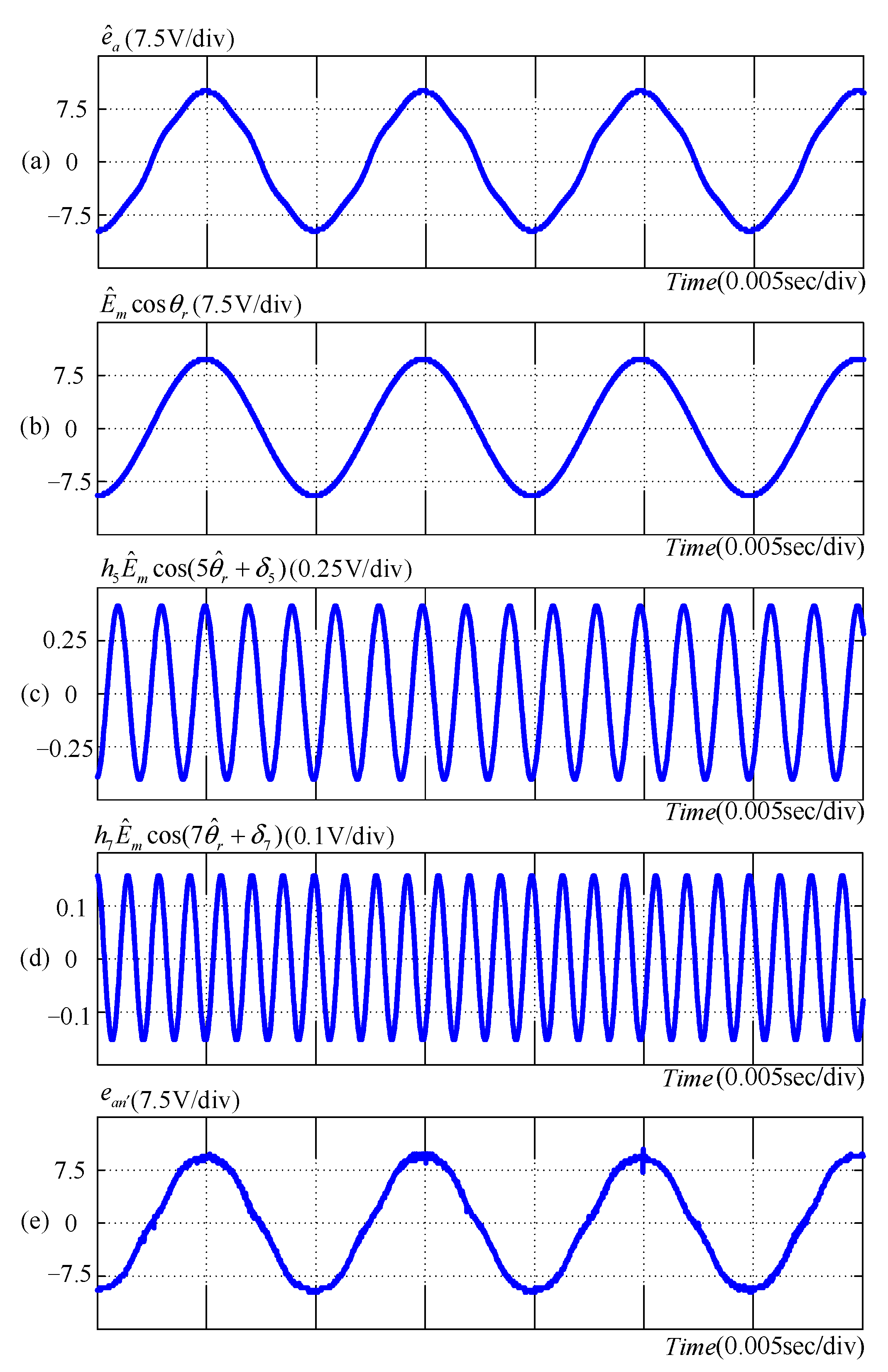
4.1. Measurement of Induced EMF

The prime mover is used to drive the three-phase permanent-magnet synchronous motor at a speed of 1500 rpm. The parameters are ω ^ r = 2 π ( 1500 60 ) ( N p 2 )   ( rad / s ) , λ m = 0.0153   ( V / rad / s ) , h 5 = 3.30 % , h 7 = 1 . 55 % , δ 5 = 31.51 ° , and δ 7 = 77.35 ° . After the simplification by the polar coordinate system, h 6 q = 4.52 % , h 6 d = 2.48 % , δ 6 q = 45.76 ° , δ 6 d = 4.91 ° are obtained, and the estimated results are shown in Figure 5. Figure 5a shows the estimated induced EMF e ^ a , which is very close to the measured e a n shown in Figure 5e, verifying the correctness of the estimation in this study. In addition, the estimated values of the fundamental wave, fifth harmonic component, and seventh harmonic component are shown in Figure 5b–d, respectively. By using the synchronously rotating reference system to transform from abc to qd reference systems in Equation (4), e ^ q r and e ^ d r can be obtained. In addition, e ^ q h r and e ^ d h r can be obtained using Equations (13) and (14) derived in this study, as shown in Figure 6. Figure 6 shows e ^ q r and e ^ d r . As e ^ q r contains the fundamental value ω ^ r λ m and the sixth harmonic component, whereas e ^ d r only contains the sixth harmonic component, their respective responses are the same as shown in Equations (11) and (12).

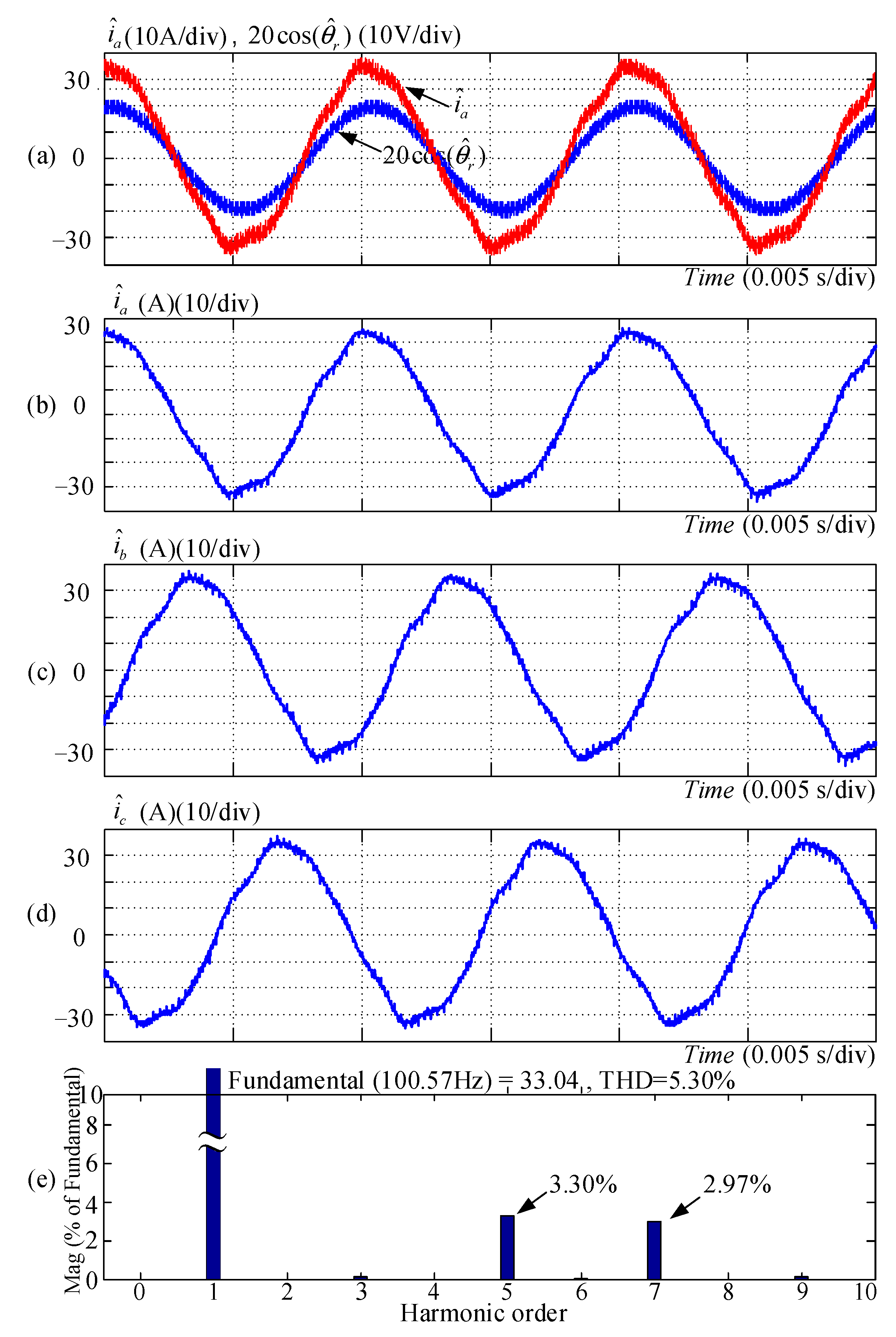
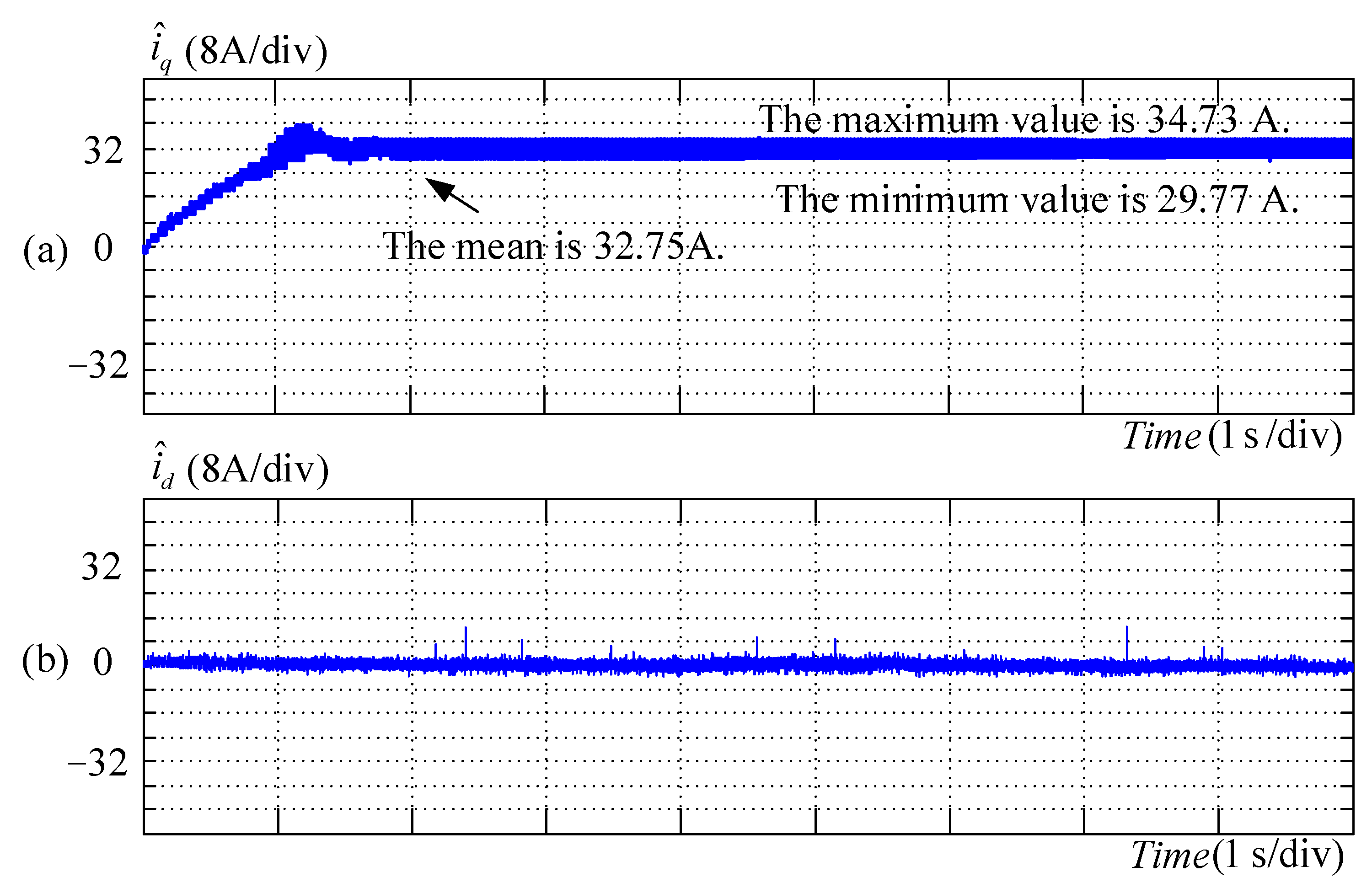
4.2. Measured Results of Induced EMF without Compensation for Harmonic Components

The current harmonic improvement control strategy is not added to the control block of Figure 1. With the effective value of the rated phase current of 23.3 A, the rated rotational speed of 1500 rpm, and the rated electromagnetic torque of 3.5 N·m, the measured results are as shown in Figure 7. It can be seen from Figure 7 that the phase current and the fundamental wave of induced EMF are in phase, and the peak value of the phase current is 33.04 A. The total harmonic distortion rate of the current is 5.30%, with 3.30% for the fifth harmonic component and 2.97% for the seventh harmonic component of the phase current. The current response transformed onto the q-axis and d-axis is shown in Figure 8. It can be seen from Figure 8 that the average value of the q-axis current is 32.75 A, and the average value of the d-axis current is not 0 A. The measurement results for speed response and electromagnetic torque are shown in Figure 9. In this study, electromagnetic torque is taken as equivalent to k T i ^ q r , which is then measured by the D/A converter. It can be seen from Figure 9 that the average value of the electromagnetic torque is 3.01 N·m, and the peak-to-peak value of the electromagnetic torque is 0.46 N·m. As torque ripple is the peak-to-peak value of electromagnetic torque divided by the average value of electromagnetic torque, the torque ripple is 15.28%.

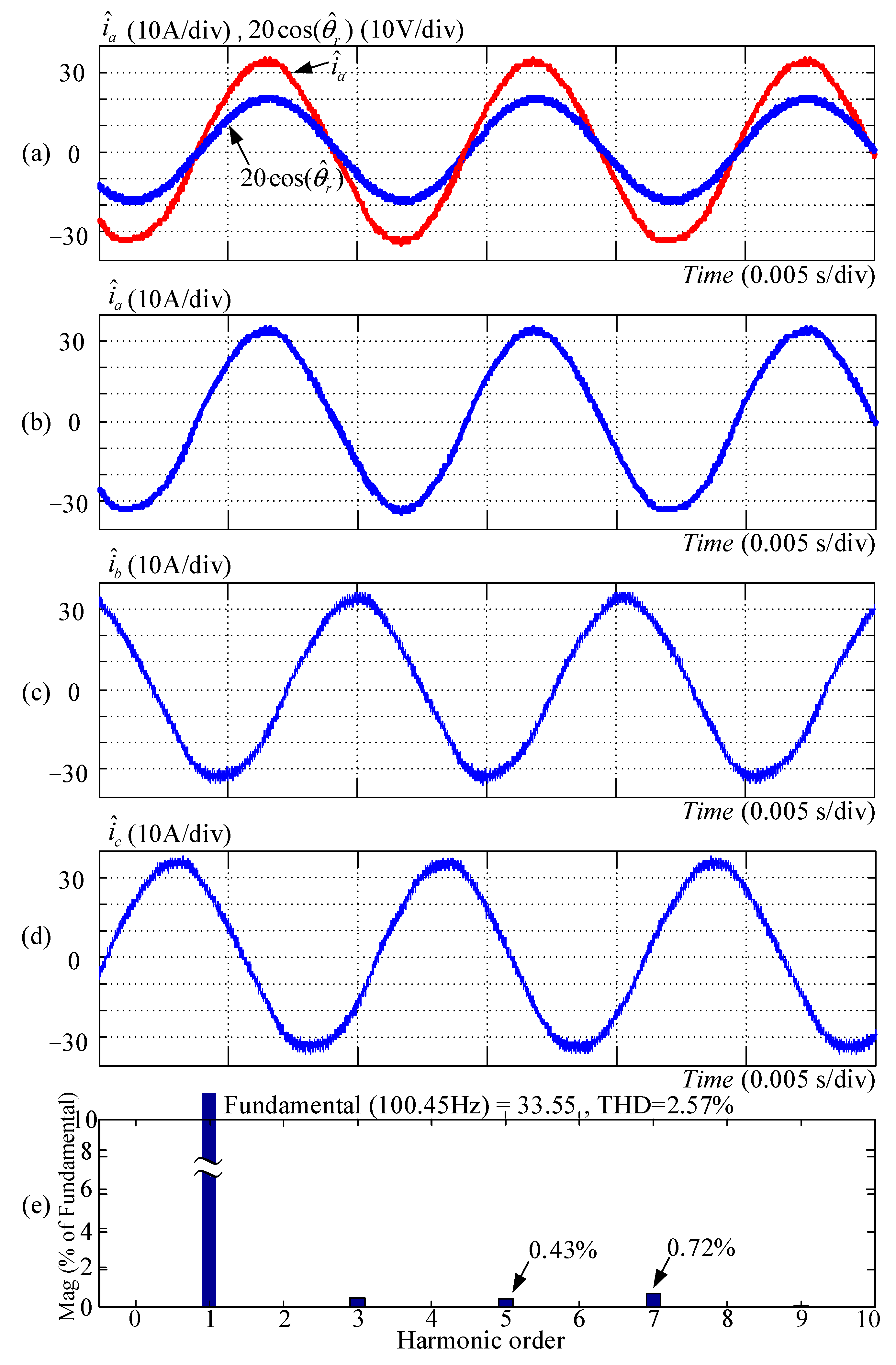
4.3. Measured Results of Induced EMF along Phase-a, Phase-b, and Phase-c with Compensation for Harmonic Components

The control block in Figure 2 shows the control strategy for induced EMF along the a-axis, b-axis, and c-axis with compensation for harmonics. The measured results are as shown in Figure 10. It can be seen from Figure 10 that the phase current and the fundamental wave of induced EMF are in phase, and the peak value of the phase current is 33.55 A. The total harmonic distortion rate of the current is 2.57%, with 0.43% for the fifth harmonic component and 0.72% for the seventh harmonic component of the phase current. The current response transformed onto the q-axis and d-axis is as shown in Figure 11. It can be seen from Figure 11 that the average value of the q-axis current is 33.25 A, and the average value of the d-axis current is approximately 0 A. The measurement results of the speed response and electromagnetic torque are shown in Figure 12. It can be seen from Figure 12 that the average value of the electromagnetic torque is 3.05 N∙m, the peak-to-peak value of the electromagnetic torque is 0.19 N∙m, and the torque ripple is 6.23%.

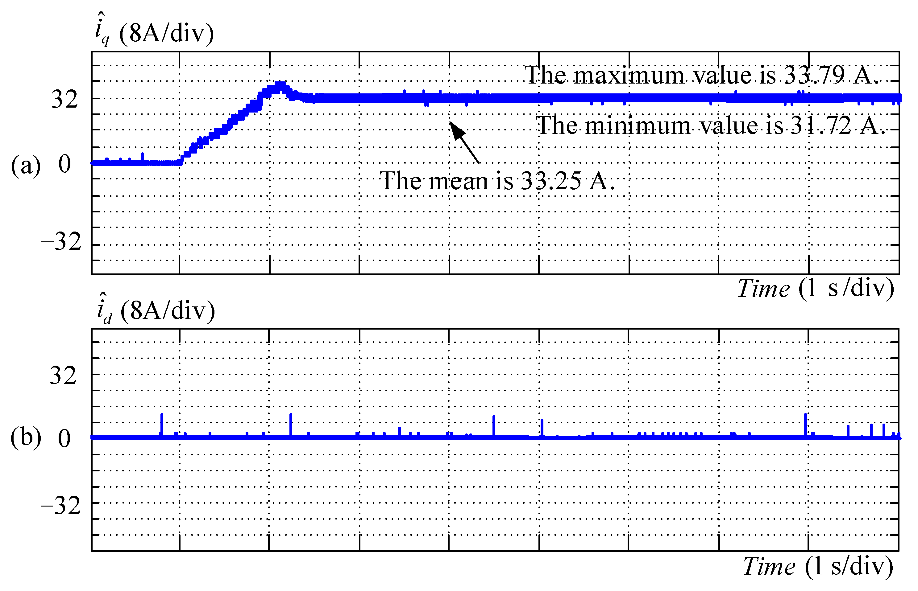
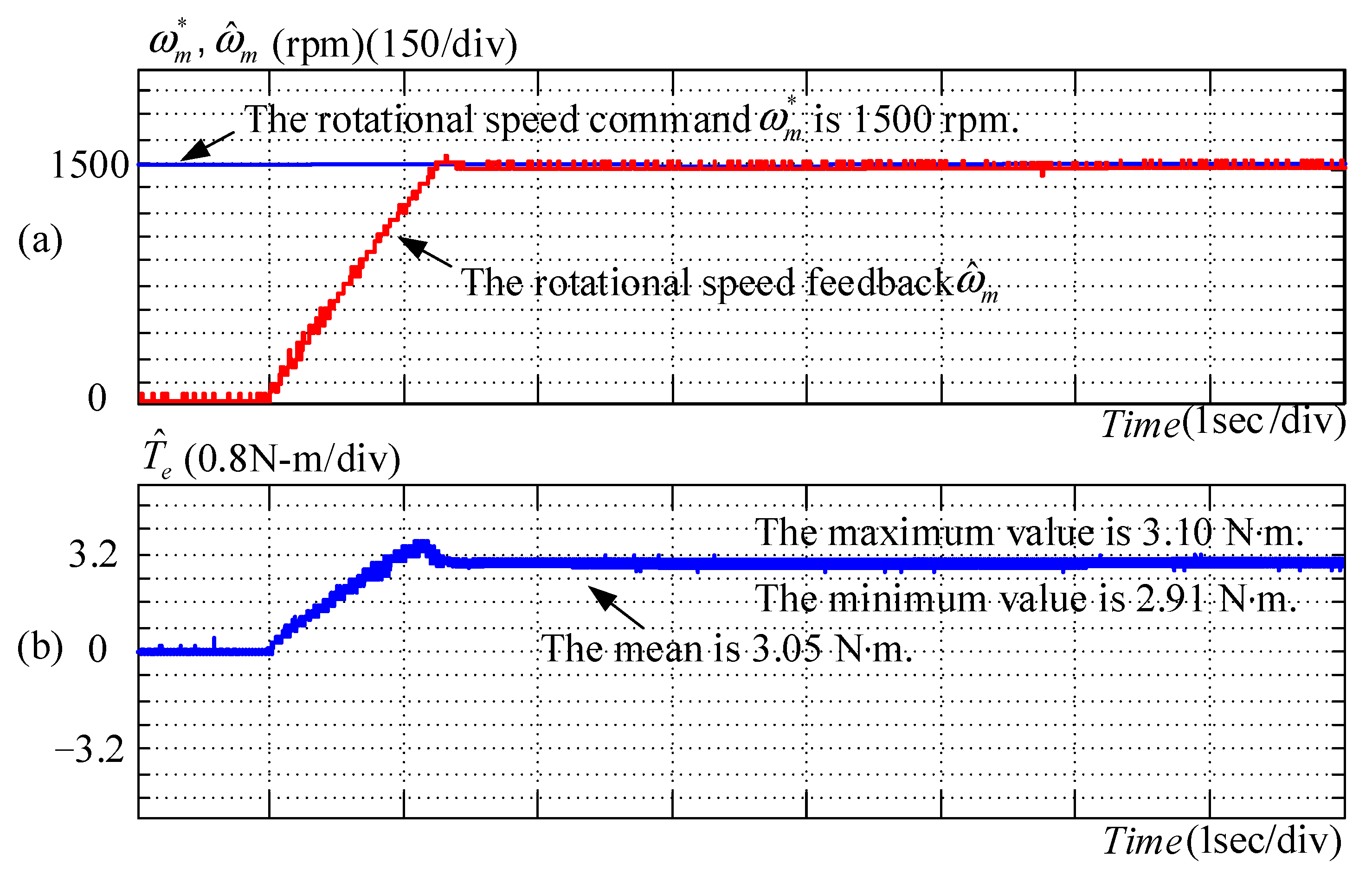
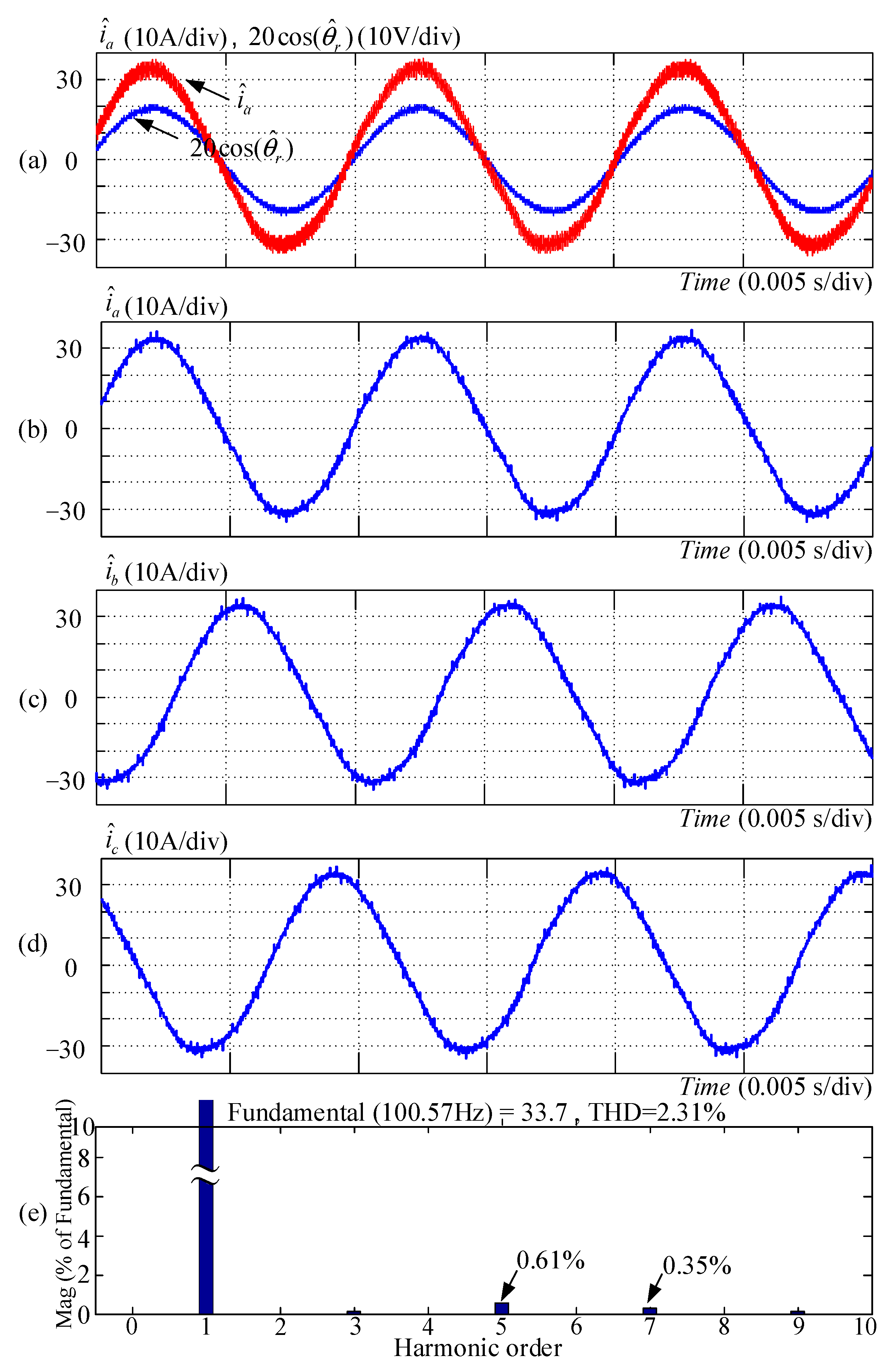
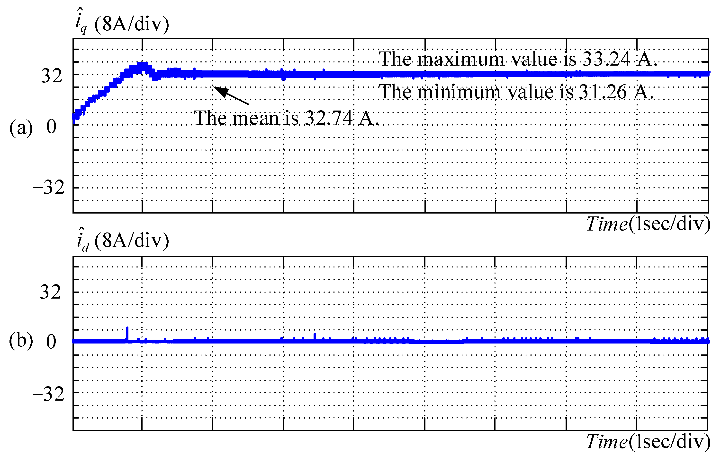
4.4. Measured Results of Induced EMF along q-Axis and d-Axis with Compensation Strategy for Harmonic Components

The control block in Figure 3 shows the control strategy for induced EMF along the q-axis and d-axis with compensation for harmonics. The measured results are as shown in Figure 13. It can be seen from Figure 13 that the phase current and the fundamental wave of induced EMF are in phase, and the peak value of the phase current is 33.70 A. The total harmonic distortion rate of the current is 2.31%, with 0.61% for the fifth harmonic component and 0.35% for the seventh harmonic component of the phase current. Compared to the result without compensation, the fifth harmonic component is reduced from 3.30% to 0.61%, and the seventh harmonic component is reduced from 2.97% to 0.35%. With reference to the experimental results of the selective current harmonic suppression method [12], the fifth harmonic content is reduced from 19.24% to 5.62%, and the seventh harmonic content is reduced from 12.87% to 4.63%. In both methods, the fifth and seventh harmonic components are reduced.
The current response transformed onto the q-axis and d-axis is as shown in Figure 14. It can be seen from Figure 14 that the average value of the q-axis current is 32.74 A, and the average value of the d-axis current is approximately 0 A. The measurement results of speed response and electromagnetic torque are shown in Figure 15. It can be seen from Figure 15 that the average value of the electromagnetic torque is 3.01 N·m, the peak-to-peak value of the electromagnetic torque is 0.18 N·m, and the torque ripple is 5.98%.

5. Conclusions

This study explains the closed-loop control strategy for rotational speed and q-axis and d-axis currents, as well as the improvement strategy for current harmonics, including the compensation strategy for induced EMF along an abc reference frame and a qd reference frame. With the compensation for harmonics in the induced EMF along the q-axis and d-axis, the total harmonic distortion rate is reduced from 5.30% to 2.31%, in which the value is reduced from 3.30% to 0.61% for the fifth harmonic component and from 2.97% to 0.35% for the seventh harmonic component. The peak-to-peak electromagnetic torque is reduced from 0.46 to 0.18 N∙m, whereas the electromagnetic torque ripple is reduced from 15.28% to 5.98%. The parameters are summarized in Table 1. It can be seen that the compensation method for harmonics is considerably effective. The method can be used to improve the jitters and ripples of the electromagnetic torque to enhance the performance of the servo drive.

Author Contributions

Conceptualization, J.-C.H. and W.-T.K.; methodology, W.-T.K.; software, W.-T.K. and J.-E.L.; validation, J.-C.H., W.-T.K., and J.-E.L.; formal analysis, W.-T.K.; investigation, J.-C.H. and W.-T.K.; resources, J.-C.H. and W.-T.K.; data curation, J.-E.L.; writing—original draft preparation, W.-T.K.; writing—review and editing, J.-C.H. and W.-T.K.; visualization, J.-E.L.; supervision, J.-C.H.; project administration, J.-C.H.; funding acquisition, J.-C.H. All authors have read and agreed to the published version of the manuscript.

Funding

This research received no external funding.

Institutional Review Board Statement

Not applicable.

Informed Consent Statement

Not applicable.

Acknowledgments

The authors would like to acknowledge the financial support of the Ministry of Science and Technology of Taiwan under grant MOST 107-2221-E-011-109-MY3.

Conflicts of Interest

The authors declare no conflict of interest.

Appendix A

Table A1. Measured results of three-phase permanent-magnet synchronous motor parameters.
ParameterValue
Equivalent resistance of each phase R s 45.87 mΩ
Equivalent inductance of each phase L s 0.338 mH
Rotor flux linkage λ m 15 . 2 × 10 3 V ( rad / s )
Fifth harmonic component of induced EMF h 5 3.30%
Seventh harmonic component of induced EMF h 7 1.55%
Rated torque3.0 N·m
Rated rotational speed1500 rpm
DC side voltage24 V
Equivalent viscosity coefficient B e q 11.6 × 10 3   N · m ( rad / s )
Equivalent moment of inertia J e q 4.43 × 10 3   kg · m 2

Appendix B

e a f ,   e b f ,   e c f Three-phase induced EMFs of the motor.
e ^ q r ,   e ^ d r The voltages observed on the q-axis and d-axis by project the three-phase induced EMFs to the rotor reference frame.
h 5 ,   h 7 The fifth and seventh harmonic components of the induced EMF.
i a ,   i b ,   i c Three-phase currents of the stator.
i ^ q r ,   i ^ d r The currents observed on the q-axis and d-axis by project the three-phase currents to the rotor reference frame.
L d , L q Direct- and quadrature-axis inductance.
R s Equivalent resistance of the stator.
T q d r The transformation matrix to project the abc to the qd reference frame.
T q d r 1 The inverse transformation matrix to project the abc to the qd reference frame.
ν a ,   ν b ,   ν c Three-phase voltages of the stator.
δ 5 ,   δ 7 Phase shifts of each phase from the fifth and seventh harmonic components, respectively.
δ 6 q ,   δ 6 d Phase shifts of q-axis and d-axis from the sixth harmonic component, respectively.
θ ^ r Electrical angle of the rotor.

References

  1. Hoang, L.H.; Robert, P.; Rene, F. Minimization of Torque Ripple in Brushless DC Motor Drives. IEEE Trans. Ind. Appl. 1986, 4, 748–755. [Google Scholar]
  2. Liang, W.; Wang, J.; Luk, P.C.; Fang, W.; Fei, W. Analytical Modeling of Current Harmonic Components in PMSM Drive with Voltage-Source Inverter by SVPWM Technique. IEEE Trans. Energy Convers. 2014, 29, 673–680. [Google Scholar] [CrossRef] [Green Version]
  3. Mattavelli, P.; Tubiana, L.; Zigliotto, M. Torque-Ripple Reduction in PM Synchronous Motor Drives Using Repetitive Current Control. IEEE Trans. Power Electron. 2005, 20, 1423–1431. [Google Scholar] [CrossRef]
  4. Lee, G.H.; Kim, S.I.; Hong, J.P.; Bahn, J.H. Torque Ripple Reduction of Interior Permanent Magnet Synchronous Motor Using Harmonic Injected Current. IEEE Trans. Magn. 2005, 44, 1582–1585. [Google Scholar]
  5. Zhu, H.; Xiao, X.; Li, Y.D. Permanent Magnet Synchronous Motor Current Ripple Reduction with Harmonic Back-EMF Compensation. In Proceedings of the International Conference on Electrical Machines and Systems, Incheon, Korea, 10–13 October 2010; pp. 1094–1097. [Google Scholar]
  6. Hwang, J.C.; Wei, H.T. The current harmonics elimination control strategy for six-leg three-phase permanent magnet synchronous motor drives. IEEE Trans. Power Electron. 2014, 29, 3032–3040. [Google Scholar] [CrossRef]
  7. Lin, J.H. Current Harmonics Improvement of Three-phase Permanent-Magnet Synchronous Motor Drives. Master’s Thesis, Department of Electrical Engineering, National Taiwan University of Science and Technology, Taipei, Taiwan, 2015. [Google Scholar]
  8. Nakao, N.; Akatsu, K. A new control method for torque ripple compensation of permanent magnet motors. In Proceedings of the International Power Electronics Conference, Sapporo, Japan, 21–24 June 2010; pp. 1421–1427. [Google Scholar]
  9. Xiao, X.; Chen, C. Reduction of Torque Ripple Due to Demagnetization in PMSM Using Current Compensation. IEEE Trans. Appl. Supercon. 2010, 20, 1068–1071. [Google Scholar] [CrossRef]
  10. Flieller, D.; Nguyen, N.K.; Wira, P.; Sturtzer, G.; Abdeslam, D.O.; Mercklé, J. A Self-Learning Solution for Torque Ripple Reduction for Nonsinusoidal Permanent-Magnet Motor Drives Based on Artificial Neural Networks. IEEE Trans. Ind. Electron. 2014, 61, 655–666. [Google Scholar] [CrossRef] [Green Version]
  11. Siami, M.; Khaburi, D.A.; Rodríguez, J. Torque Ripple Reduction of Predictive Torque Control for PMSM Drives with Parameter Mismatch. IEEE Trans. Power Electron. 2017, 32, 7160–7168. [Google Scholar] [CrossRef]
  12. Liu, G.; Chen, B.; Wang, K.; Song, X. Selective Current Harmonic Suppression for High-Speed PMSM Based on High-Precision Harmonic Detection Method. IEEE Trans Ind. Inform. 2019, 15, 3457–3468. [Google Scholar] [CrossRef]
  13. Hwang, J.C.; Lim, C.Y.; Wei, H.T. The Current Harmonics Reduction of Six-phase Permanent-magnet Synchronous Motor Drives. IEEE Trans. Power Electron. 2013, 29, 3032–3040. [Google Scholar] [CrossRef]
  14. Zhang, P.; Sizov, G.Y.; Demerdash, N.A.O. Comparison of Torque Ripple Minimization Control Techniques in Surface-mounted Permanent Magnet Synchronous Machines. In Proceedings of the IEEE International Electronics Machines and Drives Conference, Niagara Falls, ON, Canada, 15–18 May 2011; pp. 188–193. [Google Scholar]
  15. Hanselman, D. Brushless Permanent Magnet Motor Design, 2nd ed.; Magna Physics Pub: Lebanon, OH, USA, 2006. [Google Scholar]
Figure 1. Three-phase permanent-magnet synchronous motor speed and q-axis/d-axis current closed-loop control block.
Energies 14 01583 g001
Figure 2. Current harmonics improvement control block of compensation for the induced electromotive force (EMF) harmonics along the a-axis, b-axis, and c-axis in the q-axis/d-axis current closed-loop control.
Energies 14 01583 g002
Figure 3. Current harmonics improvement control block of compensation for the induced EMF harmonics along the q-axis and d-axis in the q-axis/d-axis current closed-loop control.
Energies 14 01583 g003
Figure 4. Laboratory prototype photos: (a) motor driver; (b) test bed.
Energies 14 01583 g004
Figure 5. Measured and estimated results of induced EMF of three-phase permanent-magnet synchronous motor driven by the prime mover at a speed of 1500 rpm: (a) estimated e ^ a of a-phase induced EMF; (b) E ^ m cos θ ^ r ; (c) h 5 E ^ m cos ( 5 θ ^ r + δ 5 ) ; (d) h 7 E ^ m cos ( 7 θ ^ r + δ 7 ) ; (e) e a n .
Energies 14 01583 g005
Figure 6. Estimated results of the q-axis and d-axis of the three-phase permanent-magnet synchronous motor driven by the prime mover at a speed of 1500 rpm: (a) e ^ q r ; (b) e ^ d r .
Energies 14 01583 g006
Figure 7. Measured phase currents of a three-phase permanent-magnet synchronous motor driven at 1500 rpm without compensation for harmonic components in induced EMF: (ad) measured phase currents i ^ a , i ^ b and i ^ c ; (e) spectrum of phase current i ^ a .
Energies 14 01583 g007
Figure 8. Measured q-axis and d-axis currents of a three-phase permanent-magnet synchronous motor driven at 1500 rpm without compensation for harmonic components in induced EMF: (a) measured i ^ q r ; (b) measured i ^ d r .
Energies 14 01583 g008
Figure 9. Measured rotational speed and electromagnetic torque of a three-phase permanent-magnet synchronous motor driven at 1500 rpm without compensation for harmonic components in induced EMF: (a) measured rotational speed command ω m * and rotational speed feedback ω ^ m ; (b) measured electromagnetic torque T ^ e .
Energies 14 01583 g009
Figure 10. Measured phase currents of a three-phase permanent-magnet synchronous motor driven at 1500 rpm with compensation strategy for harmonic components in induced EMF along the a-axis, b-axis, and c-axis: (ad) measured phase current i ^ a , i ^ b and i ^ c ; (e) spectrum of phase current i ^ a .
Energies 14 01583 g010
Figure 11. Measured q-axis and d-axis currents of a three-phase permanent-magnet synchronous motor driven at 1500 rpm with compensation strategy for harmonic components in induced EMF along the a-axis, b-axis, and c-axis: (a) measured i ^ q r ; (b) measured i ^ d r .
Energies 14 01583 g011
Figure 12. Measured rotational speed and electromagnetic torque of a three-phase permanent-magnet synchronous motor driven at 1500 rpm with a compensation strategy for harmonic components in induced EMF along the a-axis, b-axis, and c-axis: (a) measured rotational speed ω m * and rotational speed feedback ω ^ m ; (b) measured electromagnetic torque T ^ e .
Energies 14 01583 g012
Figure 13. Measured phase currents of a three-phase permanent-magnet synchronous motor driven at 1500 rpm with a compensation strategy for harmonic components in induced EMF along the q-axis and d-axis: (ad) measured phase currents i ^ a , i ^ b and i ^ c ; (e) spectrum of phase current i ^ a .
Energies 14 01583 g013
Figure 14. Measured q-axis and d-axis currents of a three-phase permanent-magnet synchronous motor driven at 1500 rpm with a compensation strategy for harmonic components in induced EMF along the q-axis and d-axis: (a) measured i ^ q r ; (b) measured i ^ d r .
Energies 14 01583 g014
Figure 15. Measured rotational speed and electromagnetic torque of a three-phase permanent-magnet synchronous motor driven at 1500 rpm with a compensation strategy for harmonic components in induced EMF along the q-axis and d-axis: (a) measured rotational speed command ω m * and rotational speed feedback ω ^ m ; (b) measured electromagnetic torque T ^ e .
Energies 14 01583 g015
Table 1. Comparison of the closed-loop control strategy for three-phase permanent-magnet synchronous motor speed and q-axis/d-axis currents.
Without Compensation for Harmonics in Induced EMFWith Compensation for Harmonics in Induced EMF along Phase-a, Phase-b, and Phase-cWith Compensation for Harmonics in Induced EMF along q-Axis and d-AxisExplanation
Peak-to-peak electromagnetic torque jitter0.46 N∙m0.19 N∙m0.18 N∙mThe current harmonic distortion rate with compensation strategy for the induced EMF along the q-axis and d-axis is smaller, and the torque ripple is lower.
Electromagnetic torque ripple15.28%6.23%5.98%
Phase-a current total harmonic distortion rate5.30%2.57%2.31%
Fifth harmonic component of current3.30%0.43%0.61%
Seventh harmonic component of current2.97%0.72%0.35%
Additional computational burden- h 5 ω ^ r λ m cos ( 5 θ ^ r + δ 5 ) + h 7 E ^ m ω ^ r λ m cos ( 7 θ ^ r + δ 7 ) ,
h 5 ω ^ r λ m cos ( 5 θ ^ r + δ 5 + 120 ° ) + h 7 ω ^ r λ m cos ( 7 θ ^ r + δ 7 120 ° ) ,
h 5 ω ^ r λ m cos ( 5 θ ^ r + δ 5 120 ° ) + h 7 ω ^ r λ m cos ( 7 θ ^ r + δ 7 + 120 ° )
h 6 q ω ^ r λ m cos ( 6 θ ^ r + δ 6 q ) ,
h 6 d ω ^ r λ m sin ( 6 θ ^ r + δ 6 d )
Percentage of execution time in each switching cycle (100 μs = 100%)33%60%45%
Publisher’s Note: MDPI stays neutral with regard to jurisdictional claims in published maps and institutional affiliations.

