Article

Numerical Study of Fluid Flow and Heat Transfer Characteristics in a Cone-Column Combined Heat Sink

1
School of Mechanical and Electrical Engineering, Nanjing Forestry University, Nanjing 210037, China
2
Jiangsu Sulida Advanced Technology Co., Ltd., Nanjing 210039, China
*
Author to whom correspondence should be addressed.
Energies 2021, 14(6), 1605; https://doi.org/10.3390/en14061605
Submission received: 1 March 2021 / Revised: 10 March 2021 / Accepted: 11 March 2021 / Published: 14 March 2021

Abstract

:
Temperature has a great influence on the normal operation and service life of high-power electronic components. To cope with the increasingly severe heat problems in integrated circuits, an enhanced heat transfer factor E is introduced to evaluate the comprehensive heat transfer performance of microchannel heat sinks (MCHS). The computational fluid dynamics (CFD) software was used to numerically study the fluid flow and heat transfer characteristics in the cone-column combined heat sink. The research results obtained the velocity field and pressure field distribution of the heat sink structure in the range of 100 ≤ Re ≤ 700. When Re changes, the change law of pressure drop ΔP, friction factor f, average Nussel number Nuave, average substrate temperature T, and enhanced heat transfer factor E, are compared with the circular MCHS. The results show that the uniform arrangement of the cones inside the cone-column combined heat sink can change the flow state of the cooling medium in the microchannel and enhance the heat transfer. In the range of 100 ≤ Re ≤ 700, the base temperature of the cone-column combined heat sink is always lower than the base temperature of the circular MCHS, and the average Nusselt number Nuave is as high as 2.13 times that of the circular microchannel. The enhanced heat factor E is 1.75 times that of the circular MCHS, indicating that the comprehensive heat transfer performance of the cone-column combined heat sink is significantly better than that of the circular microchannel.

1. Introduction

With the rapid development of the semiconductor industry, miniaturized and highly integrated electronic components have been widely used [1]. However, as the degree of component integration increases, its heating power also increases [2,3], and the heat flux density of some components during operation has reached 106–107 W/m2 or even higher [4]. Studies have shown that the reliability of electronic components is extremely sensitive to the operating temperature. When the component’s temperature rises to 10 °C, its reliability drops by 50%; when the temperature rises to 75–125 °C, the reliability of the product is only 20% of the initial value, or even lower [5,6]. If the surface temperature of the components cannot be effectively reduced in time, the performance of the system will decrease, and the components may even burn. Therefore, the heat dissipation problem of microdevices with high heat flux density has become an urgent task that needs to be resolved for the rapid development of electronic components.
The previous cooling method for electronic components was forced air cooling. This method has been widely used in the field of heat dissipation because of its convenience, simple design, safety and reliability, and low cost [7]. However, as the heat flux density of components continues to increase, the limited heat dissipation capacity of traditional air-cooling technology can no longer effectively solve the heat dissipation problem of high heat flux density electronic components [8,9]. In 1981, Tuckerman and Pease [10] first proposed the microchannel liquid cooling technology and conducted an experimental study on the forced convection heat transfer characteristics of water in a microchannel. It was found that when the temperature of the microchannel rose to 71 °C, it could reach a heat flux of up to 790 W/cm2. It can be seen that the microchannel heat sink (MCHS) has the advantage of a large surface-to-body ratio, high heat dissipation efficiency, and small required flow, which provides a good way to solve the heat dissipation problem of high-heat-flow electronic components [11]. Since then, many scholars have successively proposed a variety of MCHS with complex structures and studied their internal fluid flow and heat transfer performance.
Li Yifan et al. [12] proposed a combined microchannel with cavities and needle ribs, applying the principle of field synergy and entropy generation to study the influence of needle rib width, cavity width, and Reynolds number on the flow and heat transfer characteristics of the microchannel. The comprehensive performance of the microchannel was evaluated. The results showed that increasing the width of the pin ribs and the recesses can significantly reduce the heat transfer synergy angle, improve the synergy between the flow field and the temperature field, and help strengthen convective heat transfer. Xia Guodong et al. [13] proposed a new type of complex microchannel with circular pin ribs and fan-shaped cavities based on a rectangular microchannel. Through the numerical simulation of the fluid flow and heat transfer characteristics in the microchannel structure, the new channel can reduce the temperature of the lower heating surface by approximately 11 °C and reduce the thermal resistance, which is beneficial for improving the heat transfer performance of the system. Wang Zhuo et al. [14] studied the fluid flow and heat transfer characteristics in four structures: rectangular single-layer microchannels, sawtooth single-layer microchannels, rectangular double-layer microchannels, and lower rectangular upper sawtooth microchannels. They found that the heat transfer characteristics of the double-layered structure were significantly better than those of the single-layered structure. There were huge differences in the internal fluid flow and heat transfer performance of MCHS with different structures [15,16].
In addition, the scaling down from macro to micro will also lead to heat management issues [17,18]. Benedetto et al. [19] used a numerical simulation method to study the effect of circular and square cross-section on the ignition/extinction behavior of catalytic micro-combustors. Results demonstrate that, at low inlet velocities, the square cross-section channel is more resistant to extinction than the cylindrical channel. Sarli et al. [20] proposed a novel catalytic micro-combustor structure similar to the reindeer nasal cavity geometry and compared it with the standard parallel-channel under the same conditions. The numerical results show that the new catalytic micro-combustor structure has better heat retention ability than the standard parallel-channel. Due to the small size of the microchannel, its thermal management problem is more prominent, so it is urgent to optimize its geometry to find the best geometry to solve its thermal management problem [21].
This paper is based on the cone-column combined heat sink proposed by the author in previous research work [11], using CFD software to conduct a numerical study on it. The structure of the heat sink is very different from that of the heat sink proposed by previous scholars. Each microchannel is composed of an equal diameter circular section and conical column section. The conical column is evenly arranged in the channel, which can make the cooling medium flow more uniform and promote the continuous exchange of cold and hot boundary layers. The heat sink is analyzed from two aspects of fluid flow characteristics and heat transfer characteristics. The enhanced heat transfer factor E is introduced as a measure of the comprehensive performance of the MCHS, and compared with the ordinary circular MCHS, to provide a base for further improving the heat transfer performance of the heat sink.

2. Heat Sink Structure

Figure 1a is a schematic diagram of the working state of the MCHS. The entire MCHS consists of 10 single channels in parallel, each with a total length of 22.4 mm, a width of 14.5 mm, and a height of 1.5 mm. One end of the heat sink is the liquid inlet, and the other end is the liquid outlet. When the heat sink is working, the entire bottom surface of the microchannel is subjected to a thermal load with a heat flux of q. At this time, deionized water is used as the cooling medium [22] to flow in the microchannels along the X-axis, in the positive direction, to cool and dissipate the electronic components. Figure 1b shows the three-dimensional model of the cone-column combined heat sink (referred to as heat sink Z-Y) and the circular MCHS (referred to as heat sink Y) proposed by the author in a previous study. It can be seen from the figure that each cone-column combined heat sink is composed of equal-diameter circular sections and conical column sections. In order to make the flow more uniform, the conical column sections are evenly spaced in the microchannel.
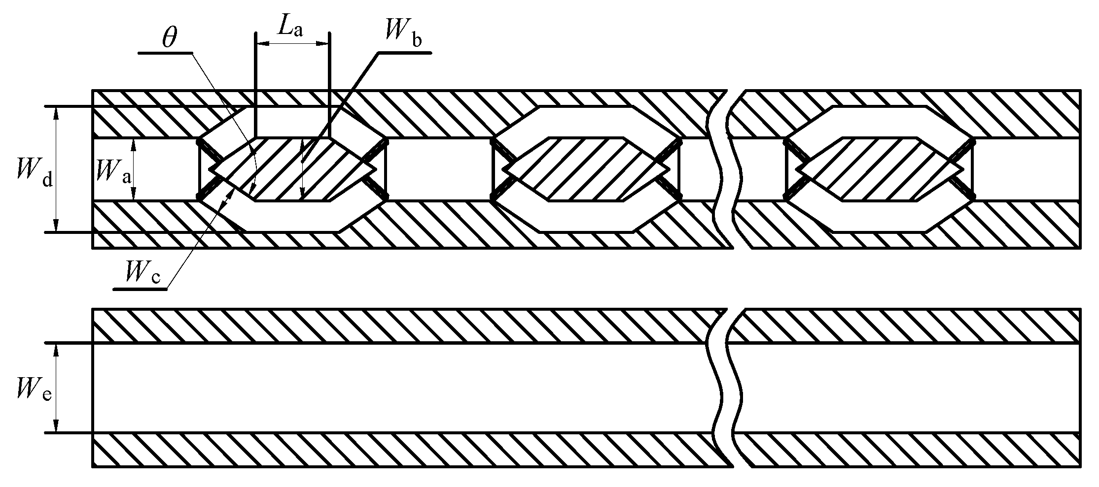
Figure 2 shows a cross-sectional view of a single-segment microchannel at z = 0.75 mm symmetrical section. The shaded part in the figure represents the solid area. The relevant structural parameters of the single-segment microchannel are listed in Table 1.

3. Numerical Models and Boundary Conditions

3.1. Governing Equation

The convective heat transfer of MCHS is a solid–liquid three-dimensional coupling heat transfer process [7]. Heat is applied to the wall of the microchannel through solid conduction, and then the heat is removed by the cooling medium through convection heat transfer [23]. The entire calculation process includes flow-field calculation and temperature field calculation. To simplify the calculation while analyzing the fluid flow and heat transfer process, the following assumptions were made for the model:
(1) The heat transfer was a single-phase liquid, and an incompressible flow occurred in the microchannel.
(2) The surface roughness of the solid wall was negligible.
(3) The thermal properties of solids and liquids remained constant during heat flow transfer.
(4) The effects of surface tension, gravity, thermal radiation, and heat loss were not considered.
(5) Because the hydraulic diameter of the microchannel was greater than 50 μm, the viscous dissipation was ignored [24].
(6) There was no slip in the wall velocity and no jump in temperature.
Based on the above assumptions, to describe the flow and heat transfer characteristics of MCHS, the continuity equation, momentum equation, and energy equation of the fluid domain were established [25,26], as shown in Equations (1), (2), and (3), respectively. The energy equation of the solid region [27] is shown in Equation (4).
Continuity equation:
u x + v y + w z = 0
Momentum equation:
ρ ( u u x + v u y + w u z ) = p x + η ( 2 u x 2 + 2 u y 2 + 2 u z 2 ) ρ ( u v x + v v y + w v z ) = p y + η ( 2 v x 2 + 2 v y 2 + 2 v z 2 ) ρ ( u w x + v w y + w w z ) = p z + η ( 2 w x 2 + 2 w y 2 + 2 w z 2 )
Energy equation for the coolant:
ρ C p ( u T x + v T y + w T z ) = λ ( 2 T x 2 + 2 T y 2 + 2 T z 2 )
Energy equation for the solid region:
x ( λ T s x ) + y ( λ T s y ) + z ( λ T s z ) = 0
where u, v, and w are the velocity components in the x, y, and z directions, respectively; ρ is the density of the cooling medium; η is the dynamic viscosity of the cooling medium; Cp is the specific heat capacity of the cooling medium; λ is the thermal conductivity; and Ts is the solid temperature.

3.2. Boundary Conditions

Service et al. [28] pointed out that when the Knudsen number (Kn) is less than 10−3, the Navier–Stokes equation and the no-slip/no-jump boundary conditions are applicable. Therefore, Kn can be used to judge whether the macro-scale mathematical model and boundary conditions are suitable for the fluid flow and heat transfer in microchannels studied in this paper. The calculation equation of Kn is as follows:
K n = Λ D h
where Λ is the average free path of the fluid molecule and DH is the equivalent diameter of the microchannel. In this paper, using deionized water as a cooling medium, the average free path of the water molecule was about 10−10 m [29,30], and the equivalent diameter of the microchannel was about 10−3 m. It can be calculated from the above equation that the magnitude of Kn is 10−7, which is much smaller than 10−3. Therefore, the Navier–Stokes equation and the no-slip/no-jump boundary conditions are still applicable in this paper. The assumptions made for the model above are hence established.
The MCHS solid material is silicon [31], and its specific heat capacity is 703 J/(kg·K), and the thermal conductivity is 149 W/(m·K). Deionized water was used as the cooling medium, and other specific boundary conditions were set as follows [32].
For the liquid part:
(1) velocity inlet: x = 0, u = uin, v = w = 0, T = Tin; (2) Pressure outlet: x = L, p = pout;
For the solid part:
(1) In the MCHS, convection and heat conduction are coupled through the solid–liquid contact surface [33]. In other words, the heat conduction of the solid wall and the convective heat transfer of the fluid coexist, and the solid–liquid contact surface has no speed slip. On the coupling surface, the temperature of the solid wall is the same as the temperature of the liquid wall, and the energy transferred at the same time is also the same. Therefore, the boundary conditions of the solid–liquid contact surface are [32]:
u = v = w = 0,
Tf = Ts,
k s T s n | ε = k f T f n | ε
(2) The upper surface of the heat sink is the boundary condition for the constant heat flow:
z = h,
k s T z = q
(3) The other walls of the heat sink are insulated:
k s T z = 0
where uin is the liquid inlet flow rate, Tin is the fluid inlet temperature, taking 293 K, pout is the fluid outlet pressure, L is the microchannel length, k is the thermal conductivity, and subscripts s, f, and ε represent solid, liquid, and solid–liquid interfaces, respectively, and q is the heat flux density, taken at 106 W/m2.
In this study, Fluent is used for the coupling calculation of the microchannel fluid flow and heat transfer process. The finite difference method is used to solve the control differential equations of fluids and solids, the velocity–pressure field is coupled by the SIMPLE algorithm, and the momentum and energy equations are both discrete using the QUICK format [34]. After the equation is discretized, it is solved iteratively by the Gauss–Seidel method. When the residual value of the variable is less than 10−6 [35], the numerical iteration calculation can be considered as convergence.

3.3. Meshing and Model Verification

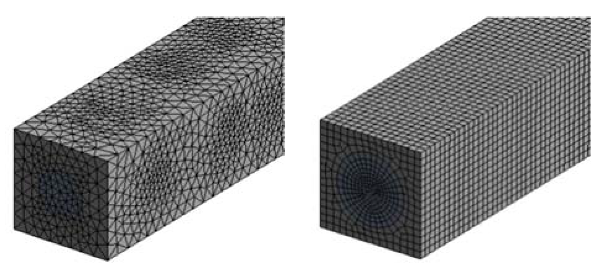
The heat sink structure in this study is composed of 10 parallel silicon microchannels with the same geometric structure. In order to shorten the calculation time, only a single microchannel was used as the research object. The geometric model was drawn using UG software, and after completion, it was imported into ICEM software for meshing. Considering the complexity of the internal structure of the cone-column combined heat sink microchannel, the grid type implemented an unstructured grid [35] and performed local encryption near the inner wall of the channel.
To ensure the accuracy of the calculation results, the grid independence needed to be tested [36]. With the cone-column combined heat sink as an example, when the inlet flow velocity uin = 1 m/s, the grid is divided by the above-mentioned grid division method, and the number of elements is 3.21, 5.345, 7.11, and 9.81 million, respectively. This was compared with another grid computing model, with a grid number of 12.25 million. The results showed that the maximum errors of the inlet and outlet pressure drops were 7.8%, 3.21%, 0.43%, and 0.37%, respectively. Therefore, the grid model with 7.11 million elements was selected as the calculation model. For the circular MCHS, the grid division method and grid independence test were the same as those of the cone-column combined heat sink. The final grid model generated by the two models is shown in Figure 3.

4. Data Processing

The heat transfer characteristics and flow characteristics are two important characteristics of the MCHS. The heat transfer characteristics directly reflect the heat dissipation performance of the microchannel, and the flow characteristics are directly related to the economy and availability of the MCHS [37]. This section presents the calculation formulas for the relevant characteristic parameters of the MCHS, which are convenient for the following evaluation of the fluid flow and heat transfer characteristics in the microchannel.
The Reynolds number is an important parameter used to characterize the fluid flow characteristics and can be calculated by the following equation:
R e = ρ u m D h μ
In the formula, um is the average flow velocity of the liquid; ρ is the density of the liquid; Dh is the hydraulic diameter of the microchannel; μ is the dynamic viscosity of water at the corresponding temperature. Among them, um can be measured with software, and its theoretical calculation equation is
u m = Q v N A
where Qv is the volume flow; N is the number of channels; A is the cross-sectional area of a single channel.
The theoretical calculation equation of Dh is:
D h = 2 W H W + H
where W and H are the cross-sectional area width and channel height of the microchannel, respectively. The value of Dh for a circular channel is the cross-sectional diameter D.
The apparent friction factor f can be obtained with the following equation:
f = 2 D h Δ P ρ L u m 2
where L is the length of the microchannel; ΔP is the pressure drop at the inlet and outlet of the channel, and the theoretical calculation equation is [38]:
Δ P = P in P out Δ P in Δ P out
where Pin and Pout are the inlet and outlet pressures of the microchannel, respectively; ΔPin and ΔPout are the inlet pressure loss and outlet pressure loss of the microchannel, respectively. This can be calculated by the following equation:
Δ P in = ρ h f
Δ P out = ρ h f
h f = ( λ l   l i +   l e d i +   ξ i ) u m 2 2
where hf is the energy loss along the way in the microchannel system, λl is the friction coefficient of the inner wall of the channel,   ξ i is the sum of the local resistance coefficients, and di is the inner diameter of the channel.
The average Nusselt number of the microchannels obtained by simulation can be calculated by the following equation:
N u ave = h ave D h k f
where kf is the thermal conductivity of the liquid; have is the average convective heat transfer coefficient, and its equation is:
h ave = Q N A c Δ T m
where Q is the heat exchange amount, Ac is the heat exchange contact area between the fluid and solid, and ΔT is the temperature difference between the fluid and the wall of the microchannel. Q and ΔT can be calculated by Equations (16) and (17), respectively:
Q = C p q m ( T out T in )
Δ T m = T w 1 2 ( T in + T out )
where qm is the mass flow rate of the fluid, Tin is the inlet fluid temperature, Tout is the outlet fluid temperature, and Tw is the heating surface temperature.
The improvement of the heat transfer effect of the microchannel is often accompanied by the deterioration of the flow effect. The enhanced heat transfer factor E is introduced to characterize the comprehensive heat transfer performance of the microchannel [39]. This parameter indicates the magnitude of the counterbalance between heat transfer and pressure drop. The calculation equation of E is shown in the following equation [40,41]:
E = N u ave f 3
where Nuave is the average Nusselt number of the microchannel and f is the apparent friction factor. The larger the value of E, the better the comprehensive heat transfer effect of the MCHS.

5. Results

5.1. Flow Characteristics

Because the cone-column combined heat sink is composed of a circular section of equal diameter and a conical column section, compared with a circular microchannel, the microchannel has a more complicated flow process inside.
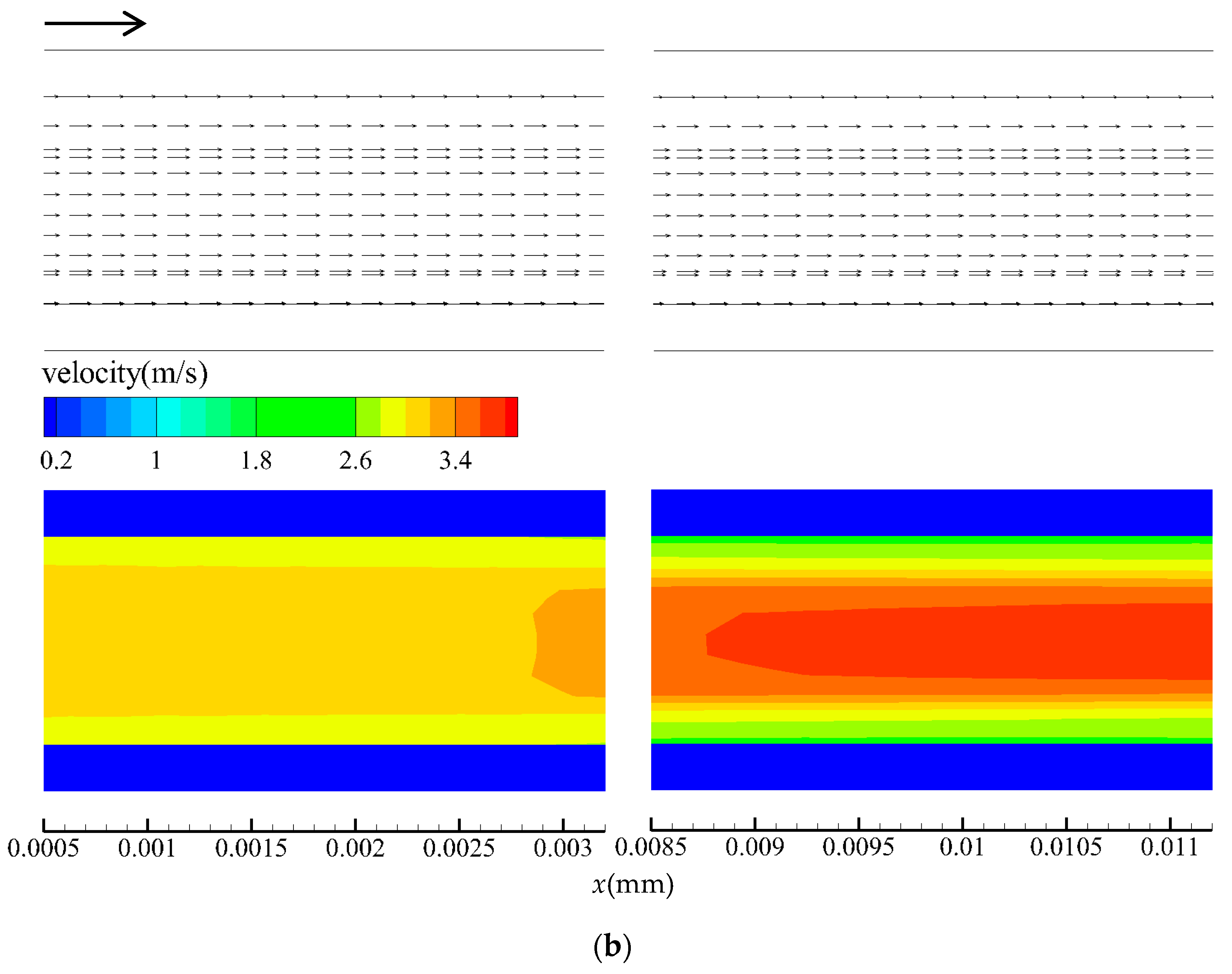
Figure 4 shows the velocity field distribution of the cone-column combined heat sink and the circular MCHS at Re = 680 and z = 0.75 mm symmetrical sections. The arrow in the figure indicates the flow direction of the cooling medium in the microchannel. As shown in Figure 4a, when the cooling medium flows into the cone-column combined heat sink, the cylindrical section area is the main flow area of the microchannel, and the velocity value is generally higher. When it reaches the tip of the cone, the tip has a stagnant effect on the fluid, causing the fluid to diverge, and the flow velocity near the tip is reduced. When it reaches the cone, it completely forms a stagnant area. When the cooling medium flows out of the cone-cylinder section and enters the cylindrical section again, the flow velocity increases to a maximum value, and the hot and cold fluids are fully mixed. For the circular MCHS, from the flow field distribution in Figure 4b, when the fluid velocity near the wall is smaller, there is no mixing of cold and hot fluid boundaries.
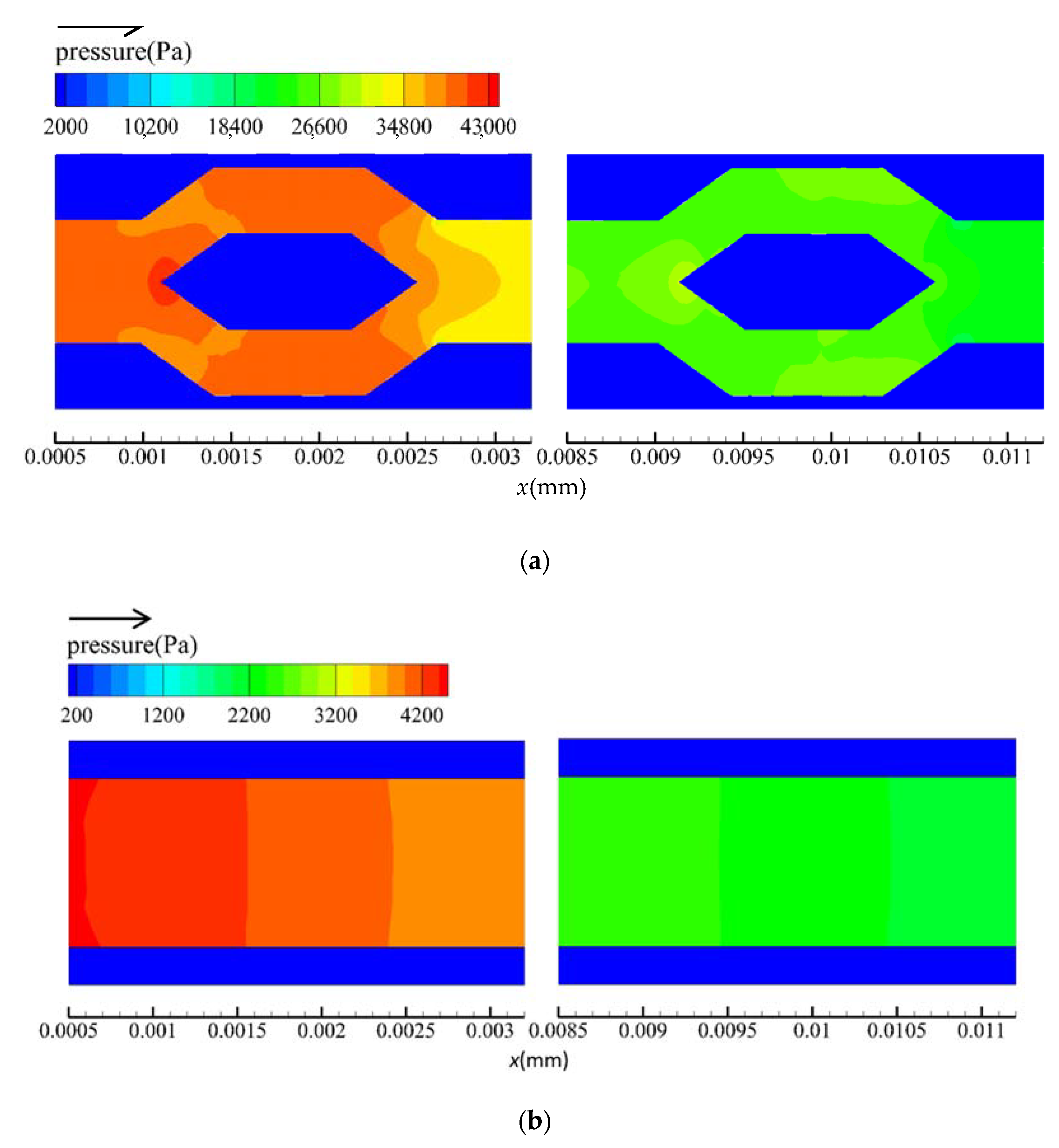
Figure 5 shows the pressure field distribution of the cone-column combined heat sink and the circular MCHS at Re = 680 and z = 0.75 mm symmetrical sections. It can be seen from Figure 5a that the pressure value of the cone-column combined heat sink had a linear downward trend throughout the length of the channel, and the pressure value increases in the local area. This phenomenon mainly occured near the tip of the cone. Because the tip has a stagnant effect on the fluid [36], the dynamic pressure was converted into static pressure, which is consistent with the decrease in flow velocity near the tip in Figure 4a. In Figure 5b, the pressure value of the circular microchannel showed a linear decreasing trend, and no sudden change occurred.
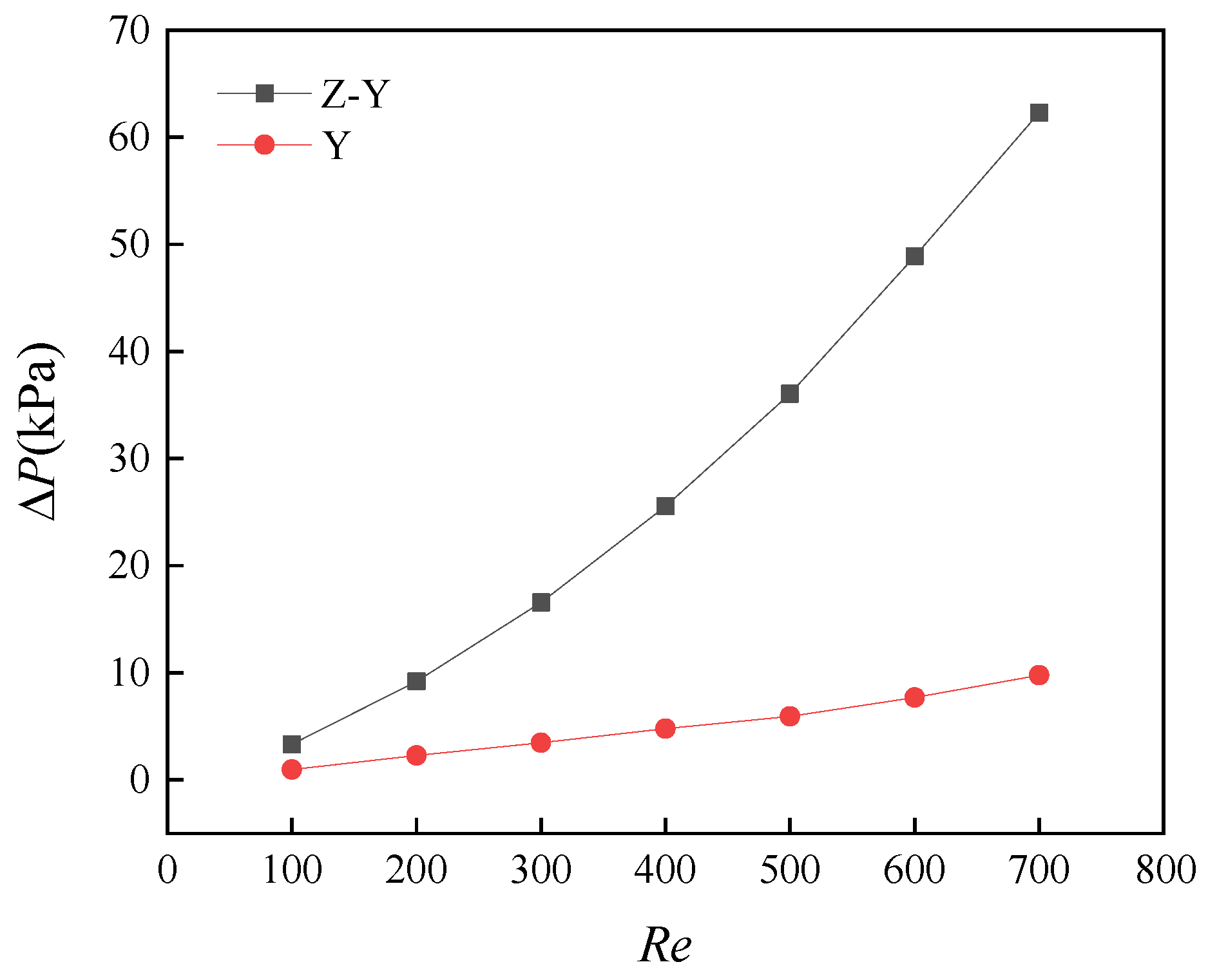
The pressure drop between the inlet and outlet of the microchannel is an important indicator for describing its flow characteristics [42]. In order to better show the pressure change of the fluid in the microchannel, Figure 6 shows the change curve of the pressure drop ΔP of the cooling medium in the cone-column combined heat sink and the circular MCHS with Re. It can be clearly seen from the figure that with the increase in Re, the pressure drop of the microchannel also increased rapidly, compared with the circular MCHS, and the rate of increase for the cone-column combined heat sink was more significant. When Re was in the range of 100 to 700, the pressure drop of the cone-column combined heat sink increased from 3.3 to 62.2 KPa, the circular MCHS increased from 0.9 to 9.8 KPa, and the pressure drop increase of the cone-column combined heat sink was 6.62 times that of the circular microchannel. The reason for this phenomenon is that the existence of the cone-cylinder section in the cone-column combined heat sink makes the flow direction of the cooling medium change periodically when flowing in the microchannel. At the same time, the fluid passes a corner from the cone-cylinder section to the cylindrical section, and in this process continues to impact the wall surface, causing a further increase in pressure drop.
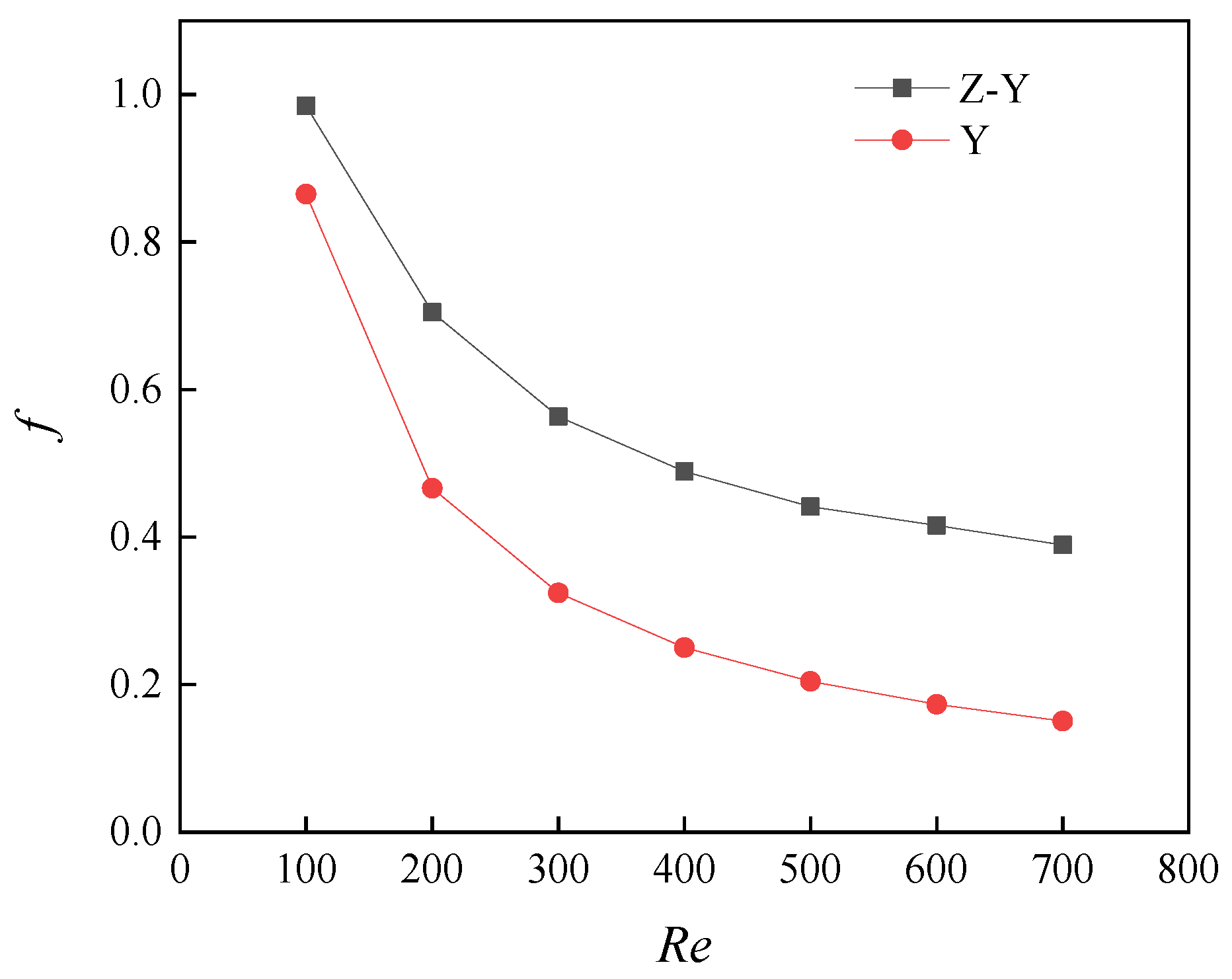
Figure 7 is the variation curve of the apparent friction factor f with Re when the cooling medium flows in the microchannel. It can be seen from the figure that with the increase of Re, the apparent friction factor f of the two microchannels show a decreasing trend. When Re exceeds 200, the apparent friction factor f of the two microchannels visibly decreases. In addition, the apparent friction factor f of the fluid in the cone-column combined heat sink is always higher than that of the circular microchannel. It can be observed that the presence of the cone-cylinder section in the cone-column combined heat sink significantly enhances the internal disturbance of the fluid in the microchannel.

5.2. Heat Transfer Characteristics

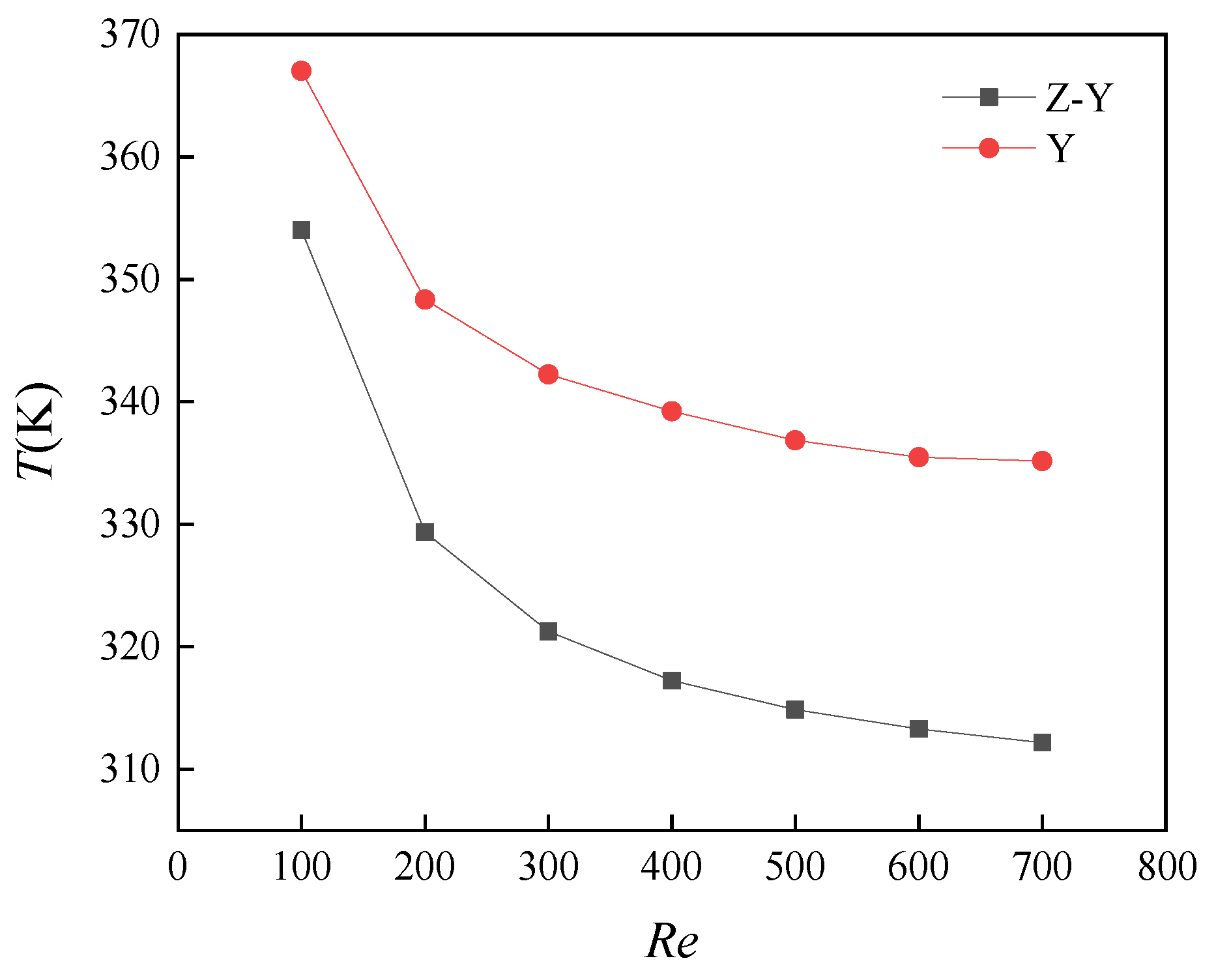
The average temperature of the substrate can directly reflect the excellent heat transfer effect of the MCHS [38]. Figure 8 shows the variation in the average temperature of the cone-column combined heat sink and the circular microchannel substrate with Re. It can be seen from Figure 8 that with the increase in Re, the average temperature of the base of the cone-column combined heat sink was always lower than that of the circular microchannel. In the process of increasing Re from 100 to 200, the average temperature of the base of the cone-column combined heat sink decreased more significantly, indicating that the cone-column combined heat sink has structural advantages compared to the circular microchannel. When Re reached 500, the average temperature of the base of the cone-column combined heat sink and circular microchannel increased with the increase in Re, and the decreasing amplitude also slowed down. This indicates that only relying on increasing the flow rate has been unable to further improve the heat transfer performance of the microchannel.
The Nusselt number is a criterion for measuring the convective heat transfer intensity of the heat transfer medium in the MCHS. It can be used to qualitatively compare the heat transfer effect of the microchannel [36].
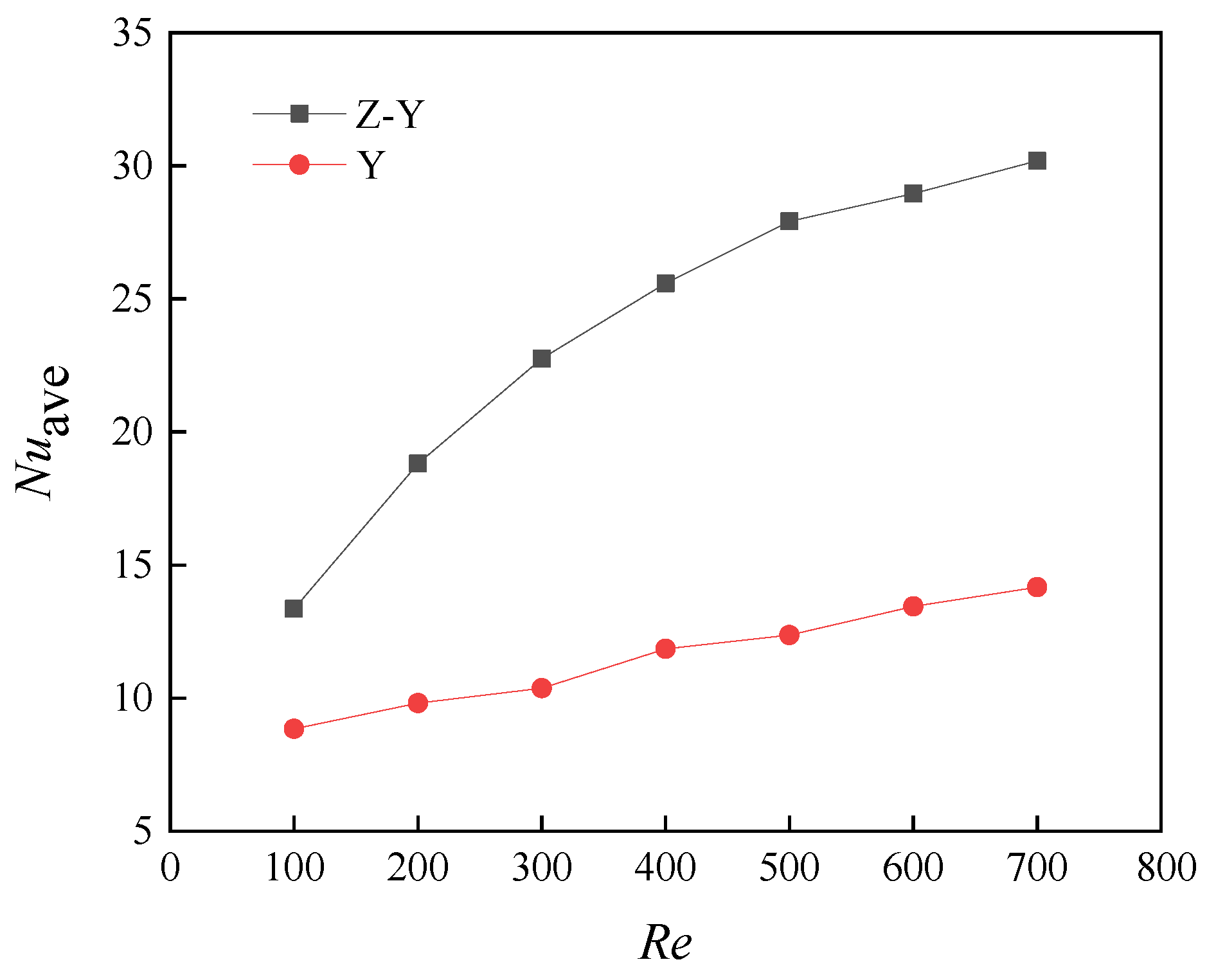
Figure 9 shows the variation curve of the average Nusselt number Nuave of the cone-column combined heat sink and circular microchannel with Re. It can be seen from the figure that the average Nusselt number of the cone-column combined heat sink was always greater than that of the circular microchannel. When Re varied from 100 to 700, the average Nusselt number of the cone-column combined heat sink was always greater than that of the circular microchannel. When Re = 700, the average Nusselt number of the cone-column combined heat sink reached 30.2, which is 2.13 times that of the circular microchannel. This indicates that with the increase in Re, the heat transfer effect of the cone-column combined heat sink is improved more significantly.

5.3. Comprehensive Performance Evaluation

From the above analysis, it can be seen that the pressure drop and apparent friction factor of the cone-column combined heat sink are always greater than those of the circular MCHS. With the change in Re, compared to the circular microchannel, the pressure drop of the cone-column combined heat sink increased more obviously, but the heat transfer effect was also more significant. In order to better measure the flow and heat transfer performance of MCHSs with different structures, this paper introduces the enhanced heat transfer factor E to evaluate the comprehensive performance of the heat sink. The calculation formula is expressed in the previous section. This dimension can consider the comprehensive performance of the heat sink in terms of the pressure drop and heat transfer effect.
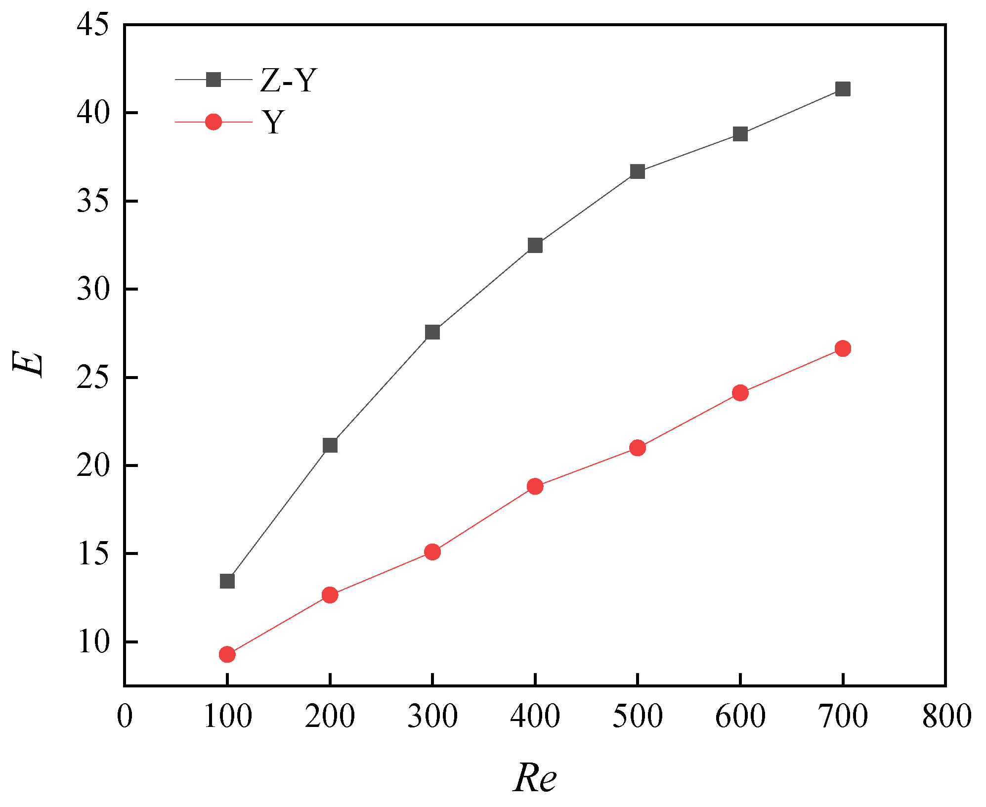
Figure 10 shows the comprehensive heat transfer performance of the cone-column combined heat sink and circular microchannel under different Re values. It can be seen from the figure that under different Re, the enhanced heat transfer factor of the cone-column combined heat sink was larger than that of the circular microchannel. When Re = 500, the enhanced heat transfer factor of the cone-column combined heat sink reached 36.7, which is 1.75 times that of the circular microchannel, indicating that its comprehensive heat transfer performance is always better than that of the circular microchannel. With the increase in Re, although the pressure drop of the cone-column combined heat sink increased significantly, the increase in heat transfer performance was greater than the increase in pressure drop.

6. Conclusions

In this study, the method of numerical simulation was used to study the fluid flow and heat transfer characteristics of the cone-column combined heat sink and compared with the ordinary circular MCHS. The main conclusions are as follows.
From the point of view of flow characteristics, the flow characteristics of ordinary circular microchannels are better than those of the cone-column combined heat sink. The pressure drop of the cone-column combined heat sink is greater than that of the circular microchannel under different Reynolds numbers, and it increases significantly with the change in Reynolds number. When Re changed from 100 to 700, the pressure drop of the cone-column combined heat sink increased from 3.3 to 62.2 kPa, and the pressure drop increased by 6.62 times that of the circular microchannel.
From the perspective of the heat exchange effect, the heat exchange effect of the cone-column combined heat sink is better. Evenly spaced in the cone-column section area of the cone-column combined heat sink, the fluid movement state is changed, the internal disturbance of the fluid is enhanced, and the heat exchange effect is strengthened. When Re = 700, the average Nusselt number of the cone-column combined heat sink reached 30.2, which is 3.6 times that of the trapezoidal silicon-based microchannel in reference [31] under the same conditions. As Re increased, the heat transfer effect of the cone-column combined heat sink increased more significantly.
The increase in heat transfer performance of the cone-column combined heat sink is greater than the increase in pressure drop. When Re = 500, the enhanced heat transfer factor of the cone-column combined heat sink reached 36.7, which is 1.75 times that of the circular MCHS, and the combined effect of flow and heat transfer was the best.
It can be seen that the microchannel structure proposed in this paper can make the microchannel obtain the best comprehensive heat transfer performance. In practical work, it can effectively reduce the heat generated by electronic components and improve the performance of electronic components. However, there are some deficiencies in this paper, mainly reflected in the following two aspects. First, the numerical model and boundary conditions are selected under certain assumptions. By modifying the model and considering some factors ignored in this paper, the flow and heat transfer state of fluid in microchannel can be better predicted and analyzed, and the results could be more accurate. Second, the effect of the cooling medium on the heat transfer performance of microchannel are ignored. The physical properties of the cooling medium also play an important role in the heat transfer performance of microchannel, which will be an important direction to improve the heat transfer performance of microchannel.

Author Contributions

Conceptualization, T.N.; formal analysis and methodology, C.M.; investigation, Q.Y.; writing—original draft preparation, W.Z.; writing—review and editing, J.S.; project administration, Y.Z. All authors have read and agreed to the published version of the manuscript.

Funding

The research was funded by the Jiangsu Provincial Key Research and Development Program Funding Project BE2017026.

Institutional Review Board Statement

Not applicable.

Informed Consent Statement

Not applicable.

Data Availability Statement

Not applicable.

Acknowledgments

The work was supported by the Jiangsu Provincial Key Research and Development Program Funding Project BE2017026.

Conflicts of Interest

The authors declare no conflict of interest.

Nomenclature

Across-sectional area of a single channel, m2
Acheat exchange contact area between fluid and solid, m2
Cpspecific heat capacity of the cooling medium, J/(kg·K)
Dhhydraulic diameter of microchannel, mm
Eenhanced heat transfer factor
fapparent friction factor
Hmicrochannel height, mm
hfenergy loss along the path in the microchannel system
haveaverage convective heat transfer coefficient, W/(m2·K)
ksthermal conductivity of the solid interface, W/(m·K)
kfthermal conductivity of the liquid interface, W/(m·K)
Llength of microchannel, mm
Lacone-column length, mm
Nnumber of channels
Nuaveaverage Nusselt number
Pinfluid inlet pressure, Pa
Poutfluid outlet pressure, Pa
ΔPpressure drop at the inlet and outlet of the channel, Pa
ΔPininlet pressure loss, Pa
ΔPoutoutlet pressure loss, Pa
qheat flux density, 106 W·m−2
qmmass flow rate of fluid, kg/s
Qheat exchange, J
Qvvolume flow, m3/s
ReReynolds number
ΔTthe temperature difference between the fluid and the wall of the microchannel, K
Tinfluid inlet temperature, 293 K
Toutoutlet fluid temperature, K
Tssolid interface temperature, K
Tffluid interface temperature, K
Twheating surface temperature, K
uvelocity components in X direction, m/s
uinliquid inlet flow rate, m/s
umthe average flow velocity of the liquid, m/s
vvelocity components in Y direction, m/s
wvelocity components in Z direction, m/s
Wmicrochannel cross-sectional area width, mm
Wacone-column combined heat sink inlet diameter, mm
Wbcone-column width, mm
Wcshunt channel width, mm
Wdshunt outer diameter, mm
Wecircular microchannel heat sink inlet diameter, mm
θcone angle, °
ρdensity of the cooling medium, kg/m3
ηdynamic viscosity of the cooling medium, Pa·s
λthermal conductivity, W/(m·K)
λlcoefficient of friction of the inner wall of the channel
  ξ i sum of local drag coefficients

References

  1. Chai, L.; Xia, G.D.; Wang, H.S. Numerical study of laminar flow and heat transfer in microchannel heat sink with offset ribs on sidewalls. Appl. Therm. Eng. 2016, 92, 32–41. [Google Scholar] [CrossRef]
  2. Hung, T.-C.; Yan, W.-M.; Wang, X.-D.; Huang, Y.-X. Optimal design of geometric parameters of double-layered microchannel heat sinks. Int. J. Heat Mass Transf. 2012, 55, 3262–3272. [Google Scholar] [CrossRef]
  3. Davarpanah, A.; Zarei, M.; Valizadeh, K.; Mirshekari, B. CFD design and simulation of ethylene dichloride (EDC) thermal cracking reactor. Energy Sources Part A Recover. Util. Environ. Eff. 2018, 41, 1573–1587. [Google Scholar] [CrossRef]
  4. Xie, G.; Li, Y.; Zhang, F.; Sundén, B. Analysis of micro-channel heat sinks with rectangular-shape-d flow obstructions. Numer. Heat Transf. Part A Appl. 2016, 69, 335–351. [Google Scholar] [CrossRef]
  5. Ambreen, T.; Kim, M.-H. Effect of fin shape on the thermal performance of nanofluid-cooled micro pin-fin heat sinks. Int. J. Heat Mass Transf. 2018, 126, 245–256. [Google Scholar] [CrossRef]
  6. Kuppusamy, N.R.; Saidur, R.; Ghazali, N.; Mohammed, H. Numerical study of thermal enhancement in micro channel heat sink with secondary flow. Int. J. Heat Mass Transf. 2014, 78, 216–223. [Google Scholar] [CrossRef]
  7. Chai, L.; Xia, G.; Zhou, M.; Li, J. Numerical simulation of fluid flow and heat transfer in a microchannel heat sink with offset fan-shaped re-entrant cavities in sidewall. Int. Commun. Heat Mass 2011, 38, 577–584. [Google Scholar] [CrossRef]
  8. Zhao, J. Flow and Heat Transfer Characteristics and Thermal Stress Analysis of Micro-Channel Heat Sink. Ph.D. Thesis, China University of Petroleum (East China), Qingdao, China, 2015. [Google Scholar]
  9. Drofenik, U.; Stupar, A.; Kolar, J.W. Analysis of theoretical limits of forced-air cooling usin-g advanced composite materials with high thermal conductivities. IEEE Trans. Compon. Packag. Manuf. Technol. 2011, 1, 528–535. [Google Scholar] [CrossRef]
  10. Tuckerman, D.; Pease, R. High-performance heat sinking for VLSI. IEEE Electron Device Lett. 1981, 2, 126–129. [Google Scholar] [CrossRef]
  11. Wei, Z.; Jianjun, S.; Tao, N.; Chenbo, M.; Qiuping, Y.; Yuyan, Z.; Zheng, W.; Sun, J.; Niu, T.; Ma, C.; et al. Structural optimization and heat transfer performance analysis of a cone-column combined heat sink. J. Heat Transf. 2020, 142, 044504. [Google Scholar] [CrossRef]
  12. Li, Y.; Wang, Z.; Yang, J.; Liu, H. Thermal and hydraulic characteristics of microchannel heat sinks with cavities and fins based on field synergy and thermodynamic analysis. Appl. Therm. Eng. 2020, 175, 115348. [Google Scholar] [CrossRef]
  13. Xia, G.; Wang, Z.; Ma, D. The characteristics of fluid flow and heat transfer in a double-layer channel of a double-layer heat source. J. B Univ. Technol. 2018, 44, 455–462. [Google Scholar]
  14. Wang, Z.; Xia, G.; Ma, D.; Yang, Z. Study on fluid flow and heat transfer characteristics in single-layer and double-layer mi-crochannels. J. Eng. Thermophys 2019, 40, 1126–1130. [Google Scholar]
  15. Bhandari, P.; Prajapati, Y.K. Thermal performance of open microchannel heat sink with variable pin fin height. Int. J. Therm. Sci. 2021, 159, 106609. [Google Scholar] [CrossRef]
  16. Zhang, J.-F.; Jia, L.; Yang, W.-W.; Taler, J.; Oclon, P. Numerical analysis and parametric optimization on flow and heat transfer of a microchannel with longitudinal vortex generators. Int. J. Therm. Sci. 2019, 141, 211–221. [Google Scholar] [CrossRef]
  17. Zarei, M.; Davarpanah, A.; Mokhtarian, N.; Farahbod, F. Integrated feasibility experimental investigation of hydrodynamic, geometrical and, operational characterization of methanol conversion to formaldehyde. Energy Sources Part A Recover. Util. Environ. Eff. 2019, 42, 89–103. [Google Scholar] [CrossRef]
  18. Valizadeh, K.; Farahbakhsh, S.; Bateni, A.; Zargarian, A.; Davarpanah, A.; Alizadeh, A.; Zarei, M. A parametric study to simulate the non-Newtonian turbulent flow in spiral tubes. Energy Sci. Eng. 2019, 8, 134–149. [Google Scholar] [CrossRef] [Green Version]
  19. Benedetto, A.D.; Sarli, V.D.; Russo, G. Effect of geometry on the thermal behavior of catalytic micro-combustors. Catal. Today 2010, 155, 116–122. [Google Scholar] [CrossRef]
  20. Sarli, V.D.; Trofa, M.; Benedetto, A.D. A novel catalytic micro-combustor inspired by the nasal geometry of reindeer: CFD modeling and simulation. Catalysts 2020, 10, 606. [Google Scholar] [CrossRef]
  21. Ehyaei, M.A.; Ahmadi, A.; Rosen, M.A.; Davarpanah, A. Thermodynamic optimization of a geothermal power plant with a genetic algorithm in two stages. Processes 2020, 8, 1277. [Google Scholar] [CrossRef]
  22. Li, J.; Peng, H.; Ling, X. Numerical study and experimental verification of transverse direction type serrated fins and field synergy principle analysis. Appl. Therm. Eng. 2013, 54, 328–335. [Google Scholar] [CrossRef]
  23. Morini, G.L. Single-phase convective heat transfer in microchannels: A review of experimental results. Int. J. Therm. Sci. 2004, 43, 631–651. [Google Scholar] [CrossRef]
  24. Koo, J.; Kleinstreuer, C. Viscous dissipation effects in microtubes and microchannels. Int. J. Heat Mass Transf. 2004, 47, 3159–3169. [Google Scholar] [CrossRef]
  25. Chai, L.; Xia, G.; Wang, L.; Zhou, M.; Cui, Z. Heat transfer enhancement in microchannel heat sinks with periodic expansion–constriction cross-sections. Int. J. Heat Mass Transf. 2013, 62, 741–751. [Google Scholar] [CrossRef]
  26. Ahmed, H.E.; Ahmed, M.I. Optimum thermal design of triangular, trapezoidal and rectangular grooved microchannel heat sinks. Int. Commun. Heat Mass Transf. 2015, 66, 47–57. [Google Scholar] [CrossRef]
  27. Li, P.; Zhang, D.; Xie, Y.; Xie, G. Flow structure and heat transfer of non-Newtonian fluids in microchannel heat sinks with dimples and protrusions. Appl. Therm. Eng. 2016, 94, 50–58. [Google Scholar] [CrossRef]
  28. Service, R.F. Labs on a chip: Coming Soon: The pocket DNA sequencer. Science 1998, 282, 399–401. [Google Scholar] [CrossRef]
  29. Mital, M. Semi-analytical investigation of electronics cooling using developing nanofluid flow in rectangular microchannels. Appl. Therm. Eng. 2013, 52, 321–327. [Google Scholar] [CrossRef]
  30. Moghari, R.M.; Akbarinia, A.; Shariat, M.H.; Talebi, F.; Laur, R. Two phase mixed convection Al2O3–water nanofluid flow in an annulus. Int. J. Multiph. Flow 2011, 37, 585–595. [Google Scholar] [CrossRef]
  31. Xia, G.; Chai, L.; Qi, J. Research on fluid flow and heat transfer characteristics of trapezoidal silicon-based microchannel heat sink. J. B Univ. Technol. 2011, 37, 1079–1084. [Google Scholar]
  32. Hung, T.C.; Huang, Y.X.; Yan, W.M. Thermal performance analysis of porous-microchannel heat sinks with different con-figuration designs. Int. J. Heat. Mass Transf. 2013, 66, 235–243. [Google Scholar] [CrossRef]
  33. Wang, R.-J.; Wang, J.-W.; Lijin, B.-Q.; Zhu, Z.-F. Parameterization investigation on the microchannel heat sink with slant rectangular ribs by numerical simulation. Appl. Therm. Eng. 2018, 133, 428–438. [Google Scholar] [CrossRef] [Green Version]
  34. Zhai, Y.; Xia, G.; Liu, X.; Wang, J. Characteristics of entropy generation and heat transfer in double-layered micro heat sinks with complex structure. Energy Convers. Manag. 2015, 103, 477–486. [Google Scholar] [CrossRef]
  35. Zhai, Y.; Zhong, G.; Li, Z. The influence of structure on the heat transfer performance of double-layer microchannel heat sink. J. Aeronaut. Dyn. 2018, 33, 565–571. [Google Scholar]
  36. Zhai, Y.; Xia, G.; Liu, X.; Li, Y. Heat transfer in the microchannels with fan-shaped reentrant cavities and different ribs based on field synergy principle and entropy generation analysis. Int. J. Heat Mass Transf. 2014, 68, 224–233. [Google Scholar] [CrossRef]
  37. Li, Y.; Xia, G.; Ma, D.; Wang, J. Field synergy and entropy generation of convective heat transfer in complex microchannels. J. Aeronaut. Dyn. 2019, 34, 1471–1482. [Google Scholar]
  38. Li, J.; Zhu, Z.; Zhao, L.; Peng, H. Experimental investigation of the heat transfer and flow characteristics of microchannels with microribs. Int. J. Heat Mass Transf. 2019, 143, 118482. [Google Scholar] [CrossRef]
  39. Webb, R. Performance evaluation criteria for use of enhanced heat transfer surfaces in heat exchanger design. Int. J. Heat Mass Transf. 1981, 24, 715–726. [Google Scholar] [CrossRef]
  40. Zhai, Y.; Xia, G.; Cui, Z. Numerical simulation of the flow and heat transfer of the spaced fan-shaped cavity microchannels. J. B Univ. Technol. 2014, 40, 627–633. [Google Scholar]
  41. Ghani, I.A.; Sidik, N.A.C.; Mamat, R.; Najafi, G.; Ken, T.L.; Asako, Y.; Japar, W.M.A. Heat transfer enhancement in microchannel heat sink using hybrid technique of ribs and secondary channels. Int. J. Heat. Mass Transf. 2017, 114, 640–655. [Google Scholar] [CrossRef]
  42. Fadzin, K.A.; Lee, A. Heat transfer enhancement in microchannel using nanofluids. Appl. Mech. Mater. 2013, 465–466, 536–540. [Google Scholar] [CrossRef]
Figure 1. Heat sink working state and geometry. (a) Schematic diagram of working status. (b) Three-dimensional model of single-stage cone-column combined heat sink and circular microchannel heat sink.
Energies 14 01605 g001
Figure 2. Cross-sectional view of micro-channel heat sink at z = 0.75 mm symmetrical section.
Energies 14 01605 g002
Figure 3. Mesh model of two microchannel heat sinks (MCHSs).
Energies 14 01605 g003
Figure 4. Velocity field distribution of MCHS. (a) Velocity field distribution of cone-column combined heat sink. (b) Velocity field distribution of circular MCHS.
Energies 14 01605 g004aEnergies 14 01605 g004b
Figure 5. Pressure field distribution of MCHS. (a) Pressure field distribution of cone-column combined heat sink. (b) Pressure field distribution of circular MCHS.
Energies 14 01605 g005
Figure 6. Change of pressure drop ΔP with Re.
Energies 14 01605 g006
Figure 7. Variation of apparent friction coefficient f with Re.
Energies 14 01605 g007
Figure 8. The variation of the average substrate temperature T with Re.
Energies 14 01605 g008
Figure 9. The variation of the average Nusselt number Nuave with Re.
Energies 14 01605 g009
Figure 10. The change of enhanced heat transfer factor E with Re.
Energies 14 01605 g010
Table 1. Microchannel structure parameters.
MicrochannelWa/mmWb/mmWc/mmWd/mmWe/mmLa/mmθ
Z-Y0.70.550.351.3/0.772
Y////1.3//
Publisher’s Note: MDPI stays neutral with regard to jurisdictional claims in published maps and institutional affiliations.