
Improving Blowout Performance of the Conical Swirler Combustor by Employing Two Parts of Fuel at Low Operating Condition

 , and
, and
Abstract
:1. Introduction
2. Fuel Distribution Ratio at Low Operating Condition
3. Testing System
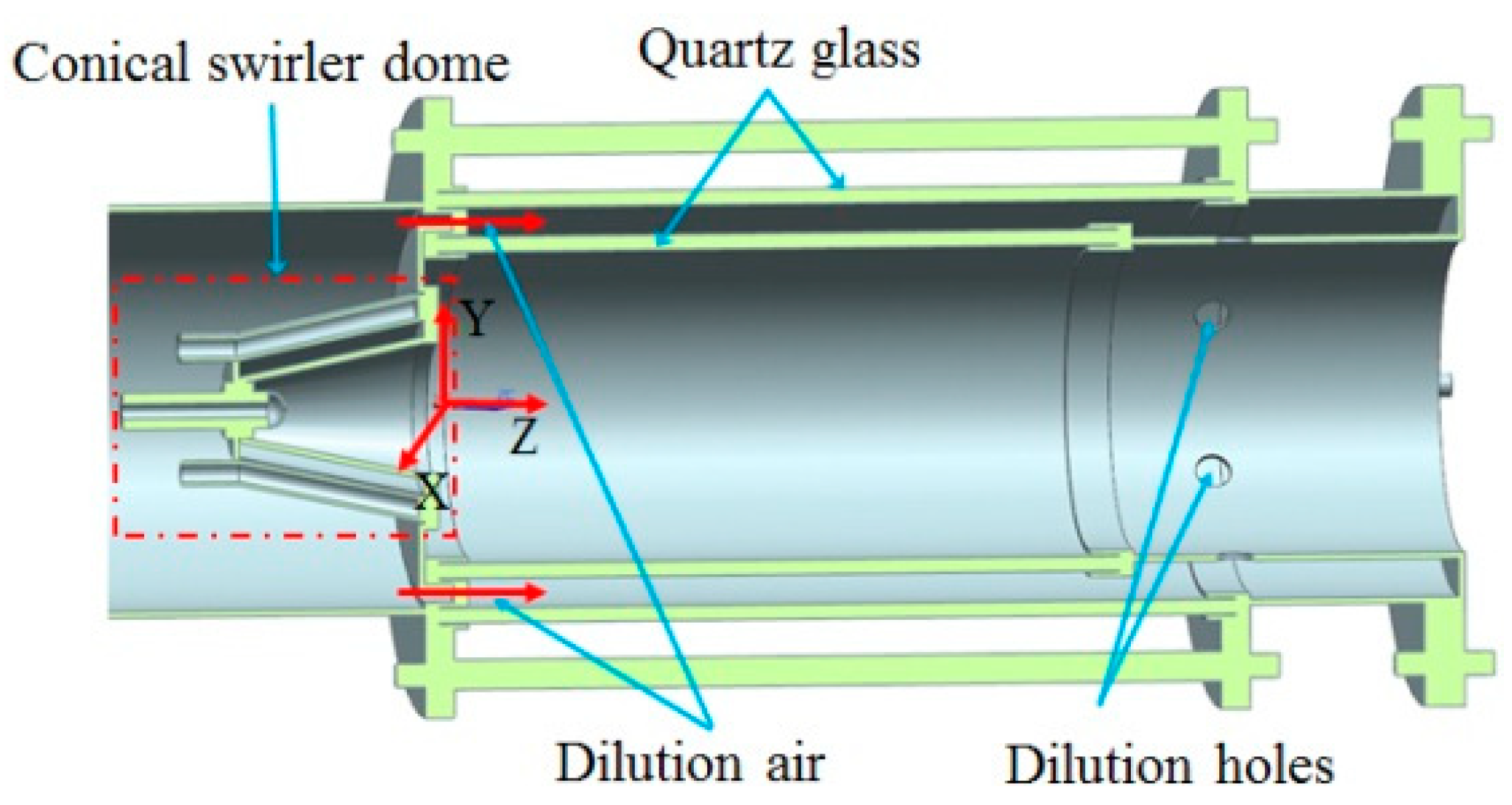
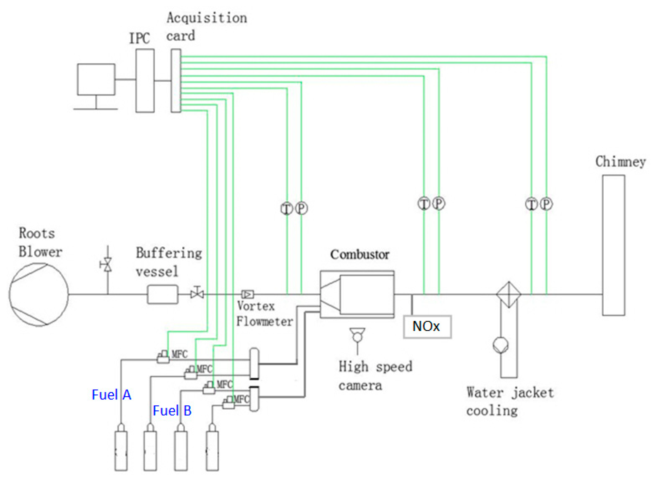
3.1. Model Combustor and Experiment Rig
3.2. Experimental Process
4. Experimental Results and Analysis
5. Numerical Computation and Analysis
6. Conclusions
- The technique employing two parts of fuel working together at low operating condition is an effective way to enhance combustion stability and to widen the boundary of the blowout.
- Increasing the fuel distribution ratio can enhance the combustion stability of the combustor, but also cause the NOx emission to increase.
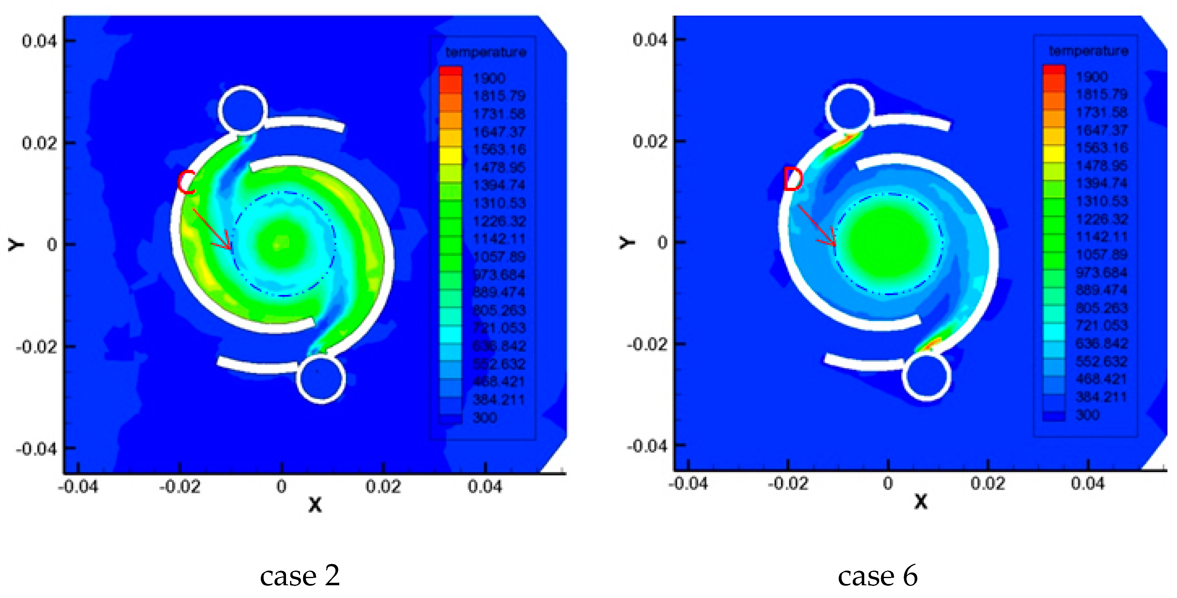
- The increase of the fuel distribution ratio contributes to the contact ratio among the zones with lower local velocity, higher temperature rise and larger Damkohler number, and that is an important reason for the improvement of blowout performance.
Author Contributions
Funding
Institutional Review Board Statement
Informed Consent Statement
Data Availability Statement
Conflicts of Interest
Nomenclature
| Nomenclature | |
| volume flow rate, L/min | |
| Ra | ratio, % |
| D | Damkohler number |
| δ | flame thickness, mm |
| Subscripts | |
| low | low operating condition |
| L | laminar |
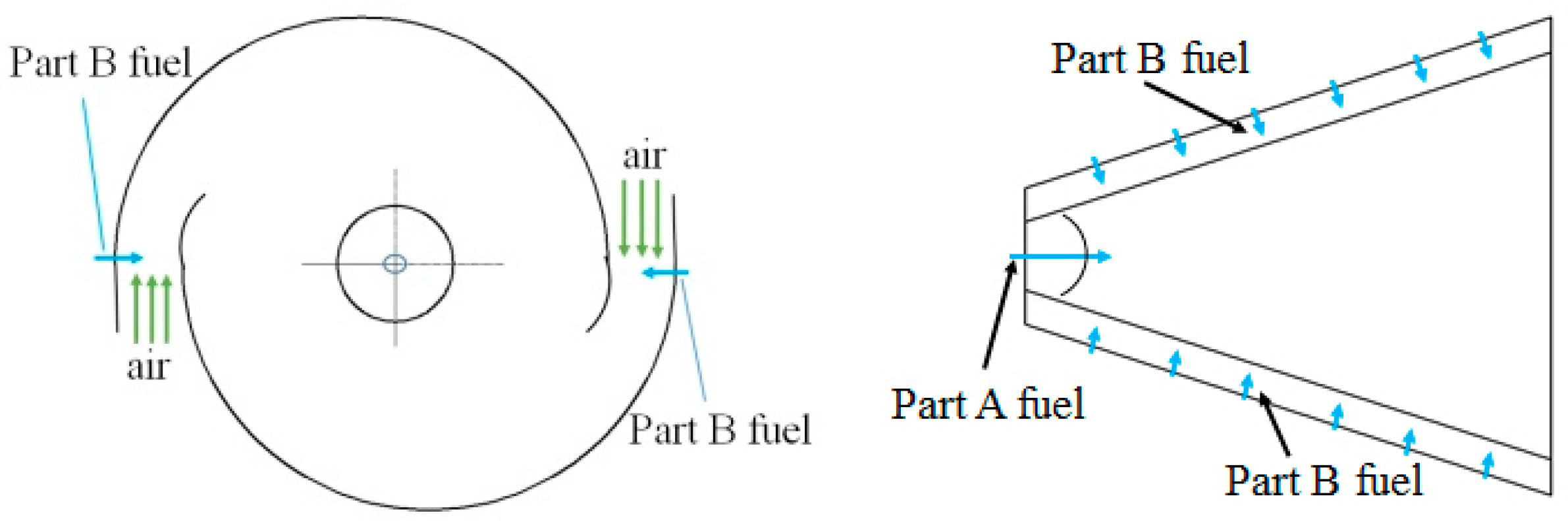
| Part, A | stream from the top of cone |
| Part, B | stream from the side of cone |
| superscript | |
| ’ | turbulent |
| τ | time, ms |
| ν | turbulent velocity, m/s |
| S | flame velocity, m/s |
| l0 | characteristic geometry length scale, mm |
| resi | residence timescale |
| chem | chemical kinetic timescale |
| rms | root mean square |
References
- Glassman, R.A.; Yetter, N.G.; Glumac, N.G. Combustion, 5th ed.; Academic Press: Cambridge, MA, USA, 2014. [Google Scholar]
- Lackner, M.; Palotás, A.B.; Franz, W. Combustion: From Basics to Applications; Wiley-VCH: Weinheim, Germany, 2013. [Google Scholar]
- Huang, Y.; Yang, V. Dynamics and Stability of Lean- premixed Swirl-stabilized Combustion. Prog. Energy Combust. Sci. 2009, 35, 293–364. [Google Scholar] [CrossRef]
- Lefebvre, A.H.; Ballal, R.D. Gas Turbine Combustion, 3rd ed.; Taylor & Francis: Abingdon, UK, 2010. [Google Scholar]
- Zajadatz, M.; Lachner, R.; Bernero, S.; Motz, C.; Flohr, P. Development and Design of Alstom’s Staged Fuel Gas Injection EV Burner for NOx Reduction. In Proceedings of the ASME Turbo Expo 2007: Power for Land, Sea, and Air, Montreal, QC, Canada, 14–17 May 2007. [Google Scholar]
- Domen, S.; Gotoda, H.; Kuriyama, T.; Okuno, Y.; Tachibana, S. Detection and prevention of blowout in a lean premixed gas-turbine model combustor using the concept of dynamical system theory. Proc. Combust. Inst. 2015, 35, 3245–3253. [Google Scholar] [CrossRef] [Green Version]
- Taamallah, S.; Labry, Z.A.; Shanbhogue, S.J.; Ghoniem, A.F. Thermo-acoustic instabilities in lean premixed swirl stabilized combustion and their link to acoustically coupled and decoupled flame macrostructures. Proc. Combust. Inst. 2015, 35, 3273–3282. [Google Scholar] [CrossRef]
- Zeng, Q.H.; Zheng, D.; Yuan, Y.X. Counter-rotating dual-stage swirling combustion characteristics of hydrogen and carbon monoxide at constant fuel flow rate. Int. J. Hydrogen Energy 2020, 45, 4979–4990. [Google Scholar] [CrossRef]
- Lee, B.J.; Im, H.G. Dynamics of bluff-body-stabilized lean premixed syngas flames in a meso-scale channel. Proc. Combust. Inst. 2017, 36, 1569–1576. [Google Scholar] [CrossRef]
- Mongia, H.; Gore, J.P.; Grinstein, F.; Gutmark, E.; Jeng, S.-M.; McDonell, V.; Menon, S.; Samuelsen, G.; Santavicca, D.; Santoro, R. Combustion Research Needs for Helping Development of Next-Generation Advanced Combustors. In Proceedings of the AIAA Joint Propulsion Conference & Exibit, Salt Lake City, UT, USA, 8–11 July 2001. [Google Scholar]
- Yuan, Y.; Lin, Y.; Liu, G. The Research of Combustor Dome Design with Three Swirlers on Widening the Operation Stability Range. Chin. J. Aerosp. Power 2004, 19, 142–147. [Google Scholar]
- Sugiyama, Y.; Takamura, R.; Koide, Y.; Watanabe, T.; Hosoi, J.; Kuyama, T.; Kawano, M.; Nakahata, T. Research and development of a 1600 C-level combustor with high heat release rate. In Proceedings of the ISABE—International Symposium on Air Breathing Engines, Melbourne, Australia; 1995; pp. 1077–1087. [Google Scholar]
- Cong, C.; Yixiang, Y.; Pengfu, X.; Dejun, Z.; Chao, Y.; Chunqing, T. A Study on Lean Blowout of Multi-vortexes-dome Model Combustor. J. Therm. Sci. 2013, 22, 366–371. [Google Scholar]
- Zeng, Q.H.; Kong, W.J.; Sui, C.J. Effect of Confinement on Combustion Characteristics in Lean Direct Injection Combustion System. In Proceedings of the ASME Turbo Expo 2013, San Antonio, TX, USA, 3–7 June 2013. GT2013-95413. [Google Scholar]
- Zeng, Q.; Yuan, Y. Flow dynamics of dual-stage counter-swirl combustor in different confinement spaces. Int. Commun. Heat Mass Transf. 2020, 116, 104633. [Google Scholar] [CrossRef]
- Biagioli, F.; Guthe, F.; Schuermans, B. Combustion Dynamics Linked to Flame Behaviour in a Partially Premixed Swirled Industrial Burner. Exp. Therm. Fluid Sci. 2008, 32, 1344–1353. [Google Scholar] [CrossRef]
- Sohn, C.H.; Cho, H.C. Numerical Analysis of Combustion Instability and Its Suppression in Gas Turbine Combustor with Swirlers Modeled on EV Premix Burners. In Proceedings of the ASME Turbo Expo 2005: Power for Land, Sea, and Air, Reno, NV, USA, 6–9 June 2005. [Google Scholar]
- Xiaoming, S.; Yixiang, Y.; Detang, Z.; Pengfu, X.; Chunqing, T. Study on the Effects of the Dome Fuel Distribution Ratio on Lean Blowout of a Model Combustor. J. Therm. Sci. 2020, 29, 52–57. [Google Scholar]
- Guyot, D.; Meeuwissen, T.; Rebhan, D. Staged Premix EV Combustion in Alstom’s GT24 Gas Turbine Engine. In Proceedings of the ASME Turbo Expo 2012: Turbine Technical Conference and Exposition, Copenhagen, Denmark, 11–15 June 2012. [Google Scholar]
- Döbbeling, K.; Hellat, J.; Koch, H. 25 Years of BBC/ABB/Alstom Lean Premix Combustion Technologies. J. Eng. Gas Turbines Power 2005, 129, 2–12. [Google Scholar] [CrossRef]
- Sattelmayer, T.; Felchlin, M.P.; Haumann, J.; Hellat, J.; Styner, D. Second-Generation Low-Emission Combustors for ABB Gas Turbines: Burner Development and Tests at Atmospheric Pressure, Transactions of the ASME. J. Eng. Gas Turbines Power 1992, 114, 118–125. [Google Scholar] [CrossRef]
- Goh, E.; Sirignano, M.; James, L.; Nair, V.; Emerson, B.; Lieuwen, T.; Seitzman, J. Prediction of minimum achievable NOx levels for fuel-staged combustors. Combust. Flame 2019, 200, 276–285. [Google Scholar] [CrossRef]
- Kang, M.S.; Jeong, H.J.; Farid, M.M.; Hwang, J. Effect of staged combustion on low NOx emission from an industrial-scale fuel oil combustor in South Korea. Fuel 2017, 210, 282–289. [Google Scholar] [CrossRef]
- Paschereit, C.O.; Flohr, P.; Knopfel, H.; Geng, W.; Steinbach, C.; Stuber, P.; Bengtsson, K.; Ephraim, J.G. Combustion Control by Extended EV Burner Fuel Lance, 2002-GT-30462. In Proceedings of the ASME Turbo Expo 2002: Land, Sea and Air, Amsterdam, The Netherlands, 3–6 June 2002. [Google Scholar]
- Houshfar, E.; Skreiberg, Ø.; Todorović, D.; Skreiberg, A.; Løvas, T.; Jovović, A.; Sørum, L. NOx emission reduction by staged combustion in grate combustion of biomass fuels and fuel mixtures. Fuel 2012, 98, 29–40. [Google Scholar] [CrossRef]
- Adouane, B.; De Jong, W.; Van Buijtenen, J.; Witteveen, G. Fuel-NOx emissions reduction during the combustion of LCV gas in an air staged Winnox-TUD combustor. Appl. Therm. Eng. 2010, 30, 1034–1038. [Google Scholar] [CrossRef]
- Chen, L.; Zhang, R.; Pan, J.; Wei, H. Effects of partitioned fuel distribution on auto-ignition and knocking under spark assisted compression ignition conditions. Appl. Energy 2020, 260, 114269. [Google Scholar] [CrossRef]
- Qinghua, Z.; Wenjun, K.; Baorui, W. Effects of fuel configuration on NOx formation characteristics within a gas turbine combustor. Chin. J. Eng. Thermophys. 2011, 32, 232–235. [Google Scholar]
- Iqbal, S.; Benim, A.C.; Fischer, S.; Joos, F.; Kluβ, D.; Wiedermann, A. Experimental and numerical analysis of natural bio and syngas swirl flames in a model gas turbine combustor. J. Therm. Sci. 2016, 25, 460–469. [Google Scholar] [CrossRef]
- Xiaoming, S.; Yixiang, Y.; Chunqing, T.; Chao, Y.; Pengfu, X. Effects of Fuel Distribution of Conical Swirler Dome on Lean Blowout of Model Combustor. Chin. J. Propuls. Technol. 2019, 40, 2262–2269. [Google Scholar]
- Guan, Y.; Novosselov, I. Damkohler Number Analysis in Lean Blow-Out of Toroidal Jet Stirred Reactor. J. Eng. Gas Turbines Power 2018, 140, 104501. [Google Scholar] [CrossRef]
- Turns, S.R. An Introduction to Combustion: Concepts and Applications, 3rd ed.; McGraw-Hill Education: New Delhi, India, 2012. [Google Scholar]
- Andrews, G.E.; Bradley, D. The Burning Velocity of Methane-Air Mixtures. Combust. Flame 1972, 19, 275–288. [Google Scholar] [CrossRef]


| Case No. | Fuel Flow Rate at Blowout (L/min) | (%) | Excess Air Coefficient at Blowout | ||
|---|---|---|---|---|---|
| case 1 | 0 | 59.6 | 59.6 | 0 | 3.9 |
| case 2 | 1 | 38 | 39 | 2.6 | 5.9 |
| case 3 | 2 | 23 | 25 | 8 | 9.2 |
| case 4 | 3 | 17 | 20 | 15 | 11.5 |
| case 5 | 3.5 | 12 | 15.5 | 22.6 | 14.8 |
| case 6 | 4 | 6 | 10 | 40 | 22.9 |
| Case No. | Air Flow Rate (m3/h) | Fuel Flow Rate (L/min) | (%) | Excess Air Coefficient | NOx (ppm) | ||
|---|---|---|---|---|---|---|---|
| case 7 | 70 | 5 | 18 | 23 | 21.7 | 4.8 | 4.1 |
| case 8 | 70 | 4 | 19 | 23 | 17.4 | 4.8 | 3.9 |
| case 9 | 70 | 3 | 20 | 23 | 13.0 | 4.8 | 3.2 |
| case 10 | 120 | 8 | 29 | 37 | 21.6 | 5.18 | 5.5 |
| case 11 | 120 | 5 | 32 | 37 | 13.5 | 5.18 | 3.5 |
Publisher’s Note: MDPI stays neutral with regard to jurisdictional claims in published maps and institutional affiliations. |
© 2021 by the authors. Licensee MDPI, Basel, Switzerland. This article is an open access article distributed under the terms and conditions of the Creative Commons Attribution (CC BY) license (http://creativecommons.org/licenses/by/4.0/).
Share and Cite
Yuan, Y.; Zeng, Q.; Yao, J.; Zhang, Y.; Zhao, M.; Zhao, L. Improving Blowout Performance of the Conical Swirler Combustor by Employing Two Parts of Fuel at Low Operating Condition. Energies 2021, 14, 1681. https://doi.org/10.3390/en14061681
Yuan Y, Zeng Q, Yao J, Zhang Y, Zhao M, Zhao L. Improving Blowout Performance of the Conical Swirler Combustor by Employing Two Parts of Fuel at Low Operating Condition. Energies. 2021; 14(6):1681. https://doi.org/10.3390/en14061681
Chicago/Turabian StyleYuan, Yixiang, Qinghua Zeng, Jun Yao, Yongjun Zhang, Mengmeng Zhao, and Lu Zhao. 2021. "Improving Blowout Performance of the Conical Swirler Combustor by Employing Two Parts of Fuel at Low Operating Condition" Energies 14, no. 6: 1681. https://doi.org/10.3390/en14061681