Article

Evolution of Internal Stress in Heterogeneous Electrode Composite during the Drying Process

1
Shanghai Institute of Applied Mathematics and Mechanics, School of Mechanics and Engineering Science, Shanghai University, Shanghai 200444, China
2
Shanghai Key Laboratory of Mechanics in Energy Engineering, Shanghai 200072, China
3
Shaoxing Institute of Technology, Shanghai University, Shanghai 200072, China
4
Institute of Materials, Shanghai University, Shanghai 200072, China
*
Authors to whom correspondence should be addressed.
Energies 2021, 14(6), 1683; https://doi.org/10.3390/en14061683
Submission received: 6 February 2021 / Revised: 15 March 2021 / Accepted: 15 March 2021 / Published: 18 March 2021

Abstract

:
The mechanical behavior of electrode composite during the drying preparation has played a crucial role in the electrochemical performance of lithium-ion batteries (LIBs). Our work aimed at developing an integrated analysis method to study the component distribution, mechanical properties, and internal stress of composite coating in the process of electrode drying. The main influence factors of drying stress were thoroughly investigated. It was found that this present model could capture not only the heterogeneity effect of inactive ingredients but also the porosity-dependent viscoelasticity of electrode composite. Meanwhile, the calculated effective modulus and stress evolution upon drying time were in acceptable accord with the experimental data. Furthermore, the rapid solidification markedly increased the drying stress in electrodes and significantly impaired the tensile strength of electrode composite due to the highly gradient distributed constituents. However, the stress level at high drying temperature could be significantly reduced by an aqueous sodium alginate binder instead of poly(vinylidene fluoride). The obtained results will be a great help in efficiently manufacturing LIB electrodes with adequate mechanical integrity.

Graphical Abstract

1. Introduction

To develop state-of-the-art lithium-ion batteries for sophisticated modern electronics and electric vehicles, a critical premise is to optimize the drying process of the electrode slurry [1,2,3]. It is well recognized that the solidification rates of electrode film influence not only the product quality but also the cost of the cell. The stress generated during coating solidification may cause cracks in the electrode films and subsequently weaken the mechanical, electrical, and electrochemical performance of the electrode [4,5,6]. However, a limited understanding of the underlying mechanisms for the drying stress in composite electrodes is one of the significant hurdles affecting the development of electrode manufacturing.
The drying kinetics of the electrode was first reported on the electrode coatings with various binders, such as poly(vinylidene fluoride) (PVDF) and carboxymethyl cellulose/styrene-butadiene rubber (CMC-SBR) [7], in which CMC was primarily used as a slurry thickener and SBR played a role of elastomeric strengthening agent [8,9]. One typical study on electrode drying was to investigate the binder distribution and adhesion force of coating films dried on current collectors at different temperatures. Due to the capillary traction in the process of drying, the polymer binders were heterogeneously dispersed throughout the electrode. It was detected to exhibit a lower concentration at the electrode coating/collector interface compared to its free surface, thus impairing the interface properties [5,10,11,12]. Subsequently, Baunach et al. investigated the delamination behavior of the dried electrodes utilizing 90° peel tests. They found that the interface could maintain a good adhesion strength at lower drying temperatures [13]. Although previous works quantitatively analyzed the binder migration during the drying step, these researchers focused on the microstructure formation, which could not capture the electrode’s macroscopic physical properties. As higher drying stress can induce electrode defects such as crack, curl, and delamination, significant efforts have been exploring the effect of drying parameters on the internal stress [14] and crack formation [4,15] in the water-based electrode. In terms of the cantilever deflection method, one observed that the drying stress would increase with the concentration of CMC-SBR [14]. Experimental results suggested that cracking intensified with increased drying temperature. The driving force for crack formation is capillary stress during drying [4]. Typically, the worsening crack severity could be attributed to the formation of holes, possibly due to film blistering during high-temperature drying. In addition, the crack initiation was affected by the electrode thickness and more likely to be generated at high drying rates [15]. The surface free energy of electrode slurry acted as a critical role for better dispersion wetting and coating adhesion during the electrode processing [16,17]. Recently, Forouzan et al. [18] developed a mesoscale particle dynamics simulation to study the evaporation-induced shrinkage ratio of the electrode film. These results are pretty helpful for understanding the binder migration and drying stress of the composite electrode. However, it is still unclear how drying-dependent physical properties impact the internal stress and how the process control of drying alters the mechanical integrity. Direct generalized predicting of drying stress would help to elucidate the underlying failure mechanism and would serve as an essential determination toward the electrode processing.
Considering the complexity of the drying-induced stress of electrode film, we believe that there exist the coupling effects of the binder motion, porosity variation, and the contact deformation between composite components. Herein, we incorporate the impact of inactive ingredients (binder and conductive agent) migration on the physical properties of electrode slurry during the drying process. A porosity-modified micromechanical model was derived for exploring the internal stress of electrode coating. The tensile measurements were carried out to determine the mechanical properties of dried coating films. The numerical results of effective modulus and drying stress were compared with the experimental results. The dependencies of peak drying stress and tensile strength on drying temperatures, polymer binders, and their concentration are also discussed to suggest the design insights for the mechanical integrity of electrode coatings during solidification.

2. Methodology

To reveal the drying mechanism of composite electrode slurry, the drying process is illustrated in Figure 1. As can be noted, wet electrode slurry with thickness h 0 is initially coated on the current collector. Then, solvent evaporation occurs on the free surface in a vacuum drying oven at a controlled drying rate, resulting in a redistribution of the composition in the slurry and shrinkage of the electrode films [19,20]. Electrode particles contact each other in the solvent volatilization stage, and dissolved binders and attached conductive additives migrate with the solvent. Finally, after the solvent is exhausted, a dried heterogeneous electrode film coating consisting of connected pores, active particles, polymer binders, and conductive agents is obtained. Due to material migration occurring only before the disconnection of pore networks or the separation of solvents, the final film thickness is almost constant [12]. Therefore, we assume that the dried electrode structure depends only on the film shrinkage step. According to the work of Font et al. [12], the solid skeleton of dry electrode coating is regarded as the mixture of active materials (AM), binders, and conductive additives (BC).

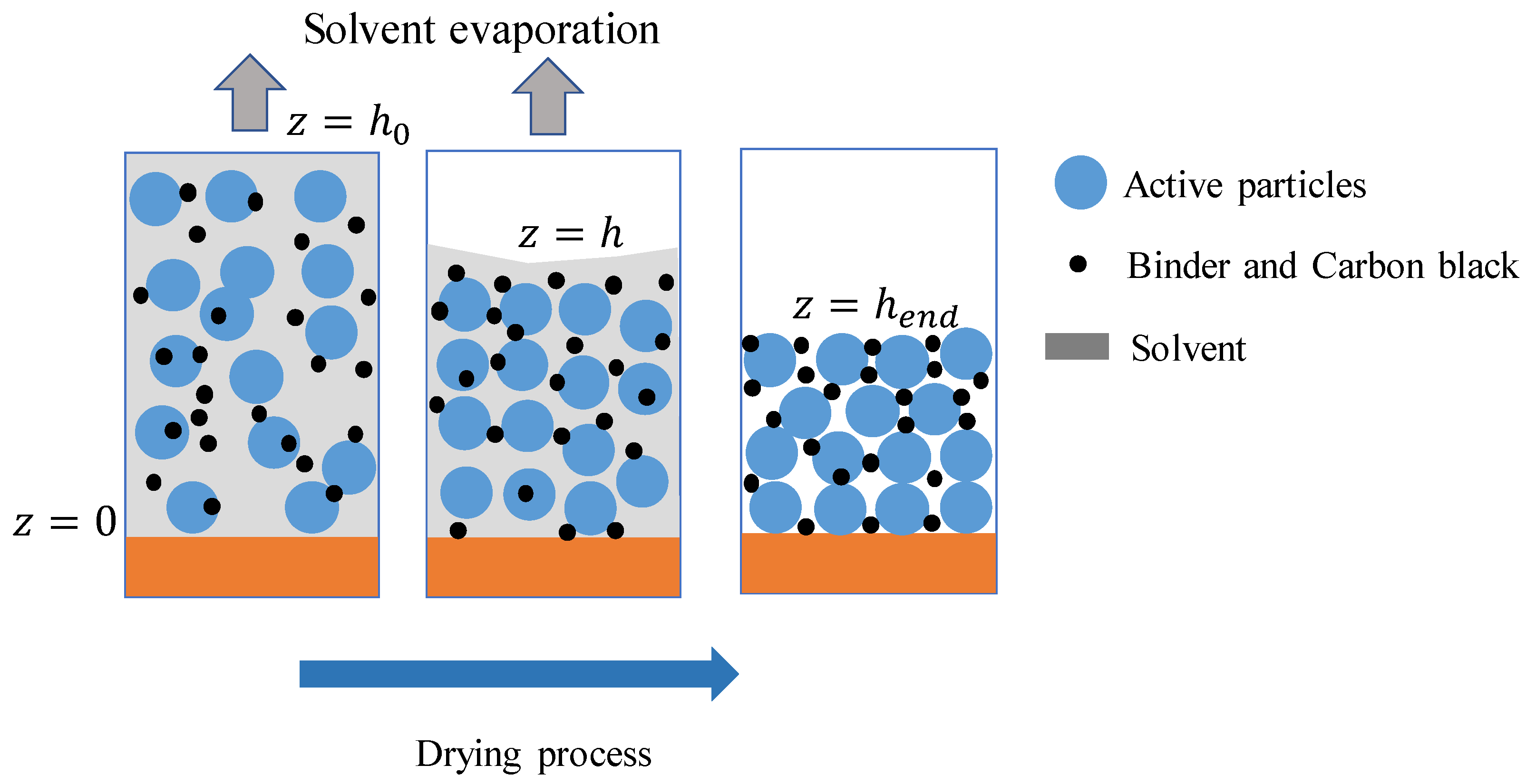
2.1. Drying Process Model

Such electrode coatings are usually composed of AM and BC in varying ratios. According to the many commercial lithium-ion battery (LIB) products, polymer binders and conductive additives are added to the solvent at a mass fraction of 1:1. We suppose that the solvent only evaporates from the top of the slurry surface, simplifying the mass transfer equation in the drying process to a one-dimensional problem along the thickness direction z , as shown in Figure 1. The coating with a thickness h after drying time t is h = h 0 0 t γ d t , the drying rate γ , which is controlled by the temperature and airflow velocity in a vacuum drying oven and can be written by γ = 2 α m ( T D T f ) × Δ h v 1 ρ s [21]. Here, Δ h v is the specific enthalpy of evaporation, α m is heat transfer coefficient, T D and T f are the drying temperature and film temperature, respectively, and ρ s is the mass density of the solvent. Within this remaining thickness, the concentration of the BC can be determined by the continuity equation according to the work of Font et al. [12], i.e.,
t [ ( 1 φ A M ) c B C ] = J z , 0 < z < h
where J = F l c B C D e f f c B C z is the volume-averaged mass flux, φ A M is the volume fraction of AM, which is usually calculated in terms of the experimental data by Jaiser et al. [19]. As the active particles are stabilized and suspended in the slurry during drying, they can be assumed to distribute along with the thickness of the electrode uniformly. Therefore, φ A M = φ A M 0 h 0 / h   is determined by the initial value φ A M 0 . D e f f = D ( 1 φ A M ) 3 / 2 is the effective diffusion coefficient of tortuous solid skeleton, where D is the diffusion coefficient of dissolved BC. F l is the flux of the liquid volume fractions in the convection term and can be written as F l = z d φ A M / d t . At the current collector/slurry interface and free evaporation surface, the law of mass conservation stipulates the adaptive boundary conditions as follows:
J | z = 0 = 0 , J | z = h = ( 1 φ A M ) c B C d h d t .  
Assuming that the film shrinkage stage determines the microstructure and properties of the electrode composite after drying, the volume fraction of each component in the solid skeleton after drying can be identified by:
φ A M e n d = φ A M 0 h 0 / h e n d , φ B C e n d = ( 1 φ A M e n d ) c B C e n d M B C / ρ B C
Among them, h e n d and c B C e n d are the thickness of the composite electrode and the concentration of the BC after the drying process is completed, respectively. M B C and ρ B C are the relevant molar mass and density of BC, separately, and ρ B C can be calculated by the density of binder and conductive additive.

2.2. Drying Stress Model

The electrode slurry is a composite material filled with AM, BC, and solvent. Because the BC system exhibits strong viscoelastic behavior [22], the electrode composite may show a non-linear viscoelastic characteristic. The solvent filling the connecting hole in the electrode is regarded as fluid, so the equivalent mechanical properties of the electrode coating can be considered as the composite of multi-component active materials, BC (i.e., binder and carbon black), and connecting hole. Over the past decades, several methods have been constructed to predict the effective properties of heterogeneous composites, which included the generalized self-consistent method (GSCM) [23], the Mori–Tanaka method (MTM) [24], and the differential schemes [25], etc. The Mori–Tanaka method considers the interaction of particles in the matrix and can capture the major characteristic of the composites. The MTM is widely used because it can give a simple and explicit expression of the effective elastic modulus of composite materials. According to Chen et al.’s work [26], the effective relaxation modulus can be mathematically described by the MTM [24,27]. The shear modulus of the BC matrix is assumed as Prony series by:
G B C = G + G 1 e x p ( t / τ )
where G and τ are relaxation modulus and relaxation time of BC, respectively. The shape of active materials is approximately assumed to be spherical, and its diameter is almost 10 micrometers. The surface effect can be neglected when the spherical inclusion radius is larger than 50 nm [28]. As further drying is in progress, holes in BC will build up. Moreover, the poroviscoelastic characteristic of composites and dynamic evolution of porosity during the drying process must be considered. Therefore, we may modify the elastic constants of BC by the coefficient ( φ B C / ( 1 φ A M ) ) n as
G B C = ( φ B C / ( 1 φ A M ) ) n ( G + G 1 e x p ( t / τ ) )
Herein, the value of n   is set to 2 [29,30]. Then, the viscoelastic matrix is written as Laplace transform to form formal linear elasticity, and the effective shear modulus G ¯ e and bulk modulus K ¯ e in Laplace space is also written by
G ¯ e G ¯ B C = 1 + φ A M ( G A M G ¯ B C ) G ¯ B C + φ B C ( G A M G ¯ B C ) S s K ¯ e K ¯ B C = 1 + φ A M ( K A M K ¯ B C ) K ¯ B C + φ B C ( K A M K ¯ B C ) S m
where φ A M and φ B C is the volume fraction of AM and BC, respectively. G A M is the shear modulus of AM. S s = ( 8 10 v B C ) / 15 ( 1 v B C ) and S m = ( 1 + v B C ) / 3 ( 1 v B C ) is the Eshelby tensor for a spherical inclusion [31], in which v B C is Poisson’s ratio of BC. Symbol ‘-’ stands for Laplace transform f ¯ ( s ) = 0 f ( t ) e st d t . Therefore, the inverse transformation of the Equation (6) can be expressed by
G e = G 0 s 1 / s 2 + G 1 s 3 e x p ( t τ ) + G A M ( s 5 / s 2 s 4 ) e x p ( s 2 s 4 t τ )
where
s 1 = G 0 φ A M G 0 G A M φ A M + G 0 S s φ B C G A M S s φ B C
s 2 = G 0 S s φ B C G 0 G A M S s φ B C
s 3 = φ B C / ( S s φ B C 1 ) + 1
s 4 = G 0 S s φ B C G 0 G 1 + G 1 S s φ B C G A M S s φ B C
s 5 = G 1 G A M S s φ A M φ B C / ( 1 S s φ B C )
It is known that the RR model was used to describe the drying-induced deformation of a wet latex film, as verified by the classical cantilever technique [32]. As a consequence, based on the RR model [32,33] for the viscoelastic deformation of a pair of particles in the saturated solid, the constitutive relation of the viscoelastic particle system is modified by
σ i j = δ i j P c 3 M μ e φ S 0 140 d ε 0 2 d t ( δ i j + 4 δ i 3 δ j 3 ) 3 M γ R φ S 0 ε 0 2 80 R ( 3 δ i j + 4 δ i 3 δ j 3 )
where μ e is the electrode particle viscosity written by τ = μ e / G e , σ i j   is the macroscopic stress tensor, δ i j is the Kronecker delta, P c is the capillary pressure, M is the coordination number, φ S 0 is the volume fraction of solid skeleton. Besides, ε 0 is the bulk strain during the film shrinking stage, which relates to the volume fraction of solid contents, ε 0 = 1 φ S 0 φ S = 1 ( φ A M 0 + φ B C 0 ) ( φ A M + φ B C ) , and the above drying process model can acquire the volume fraction. The RR model assumed that the interfacial tension does not contribute to the deformation. In Equation (8), we address the effect of surface tension γ R on the drying stress compared to the RR model [32]. The constraint imposed by the current collector induces biaxial stress in the plane of the film, σ 11 = σ 22 . The capillary pressure P c and drying stress σ 11 can be expressed as
P c = 3 M μ e φ S 0 14 ( 1 φ S 0 φ S ) φ S 0 φ S d φ S d t 21 M γ R φ S 0 80 R ( 1 φ S 0 φ S ) 2 σ 11 = 6 M μ e φ S 0 35 ( 1 φ S 0 φ S ) φ S 0 φ S d φ S d t + 3 M γ R φ S 0 20 R ( 1 φ S 0 φ S ) 2
The equivalent particle viscosity μ e and shrinkage strain of the electrode composite depend on the drying process; therefore, the drying-induced stress evolution can be determined step by step.

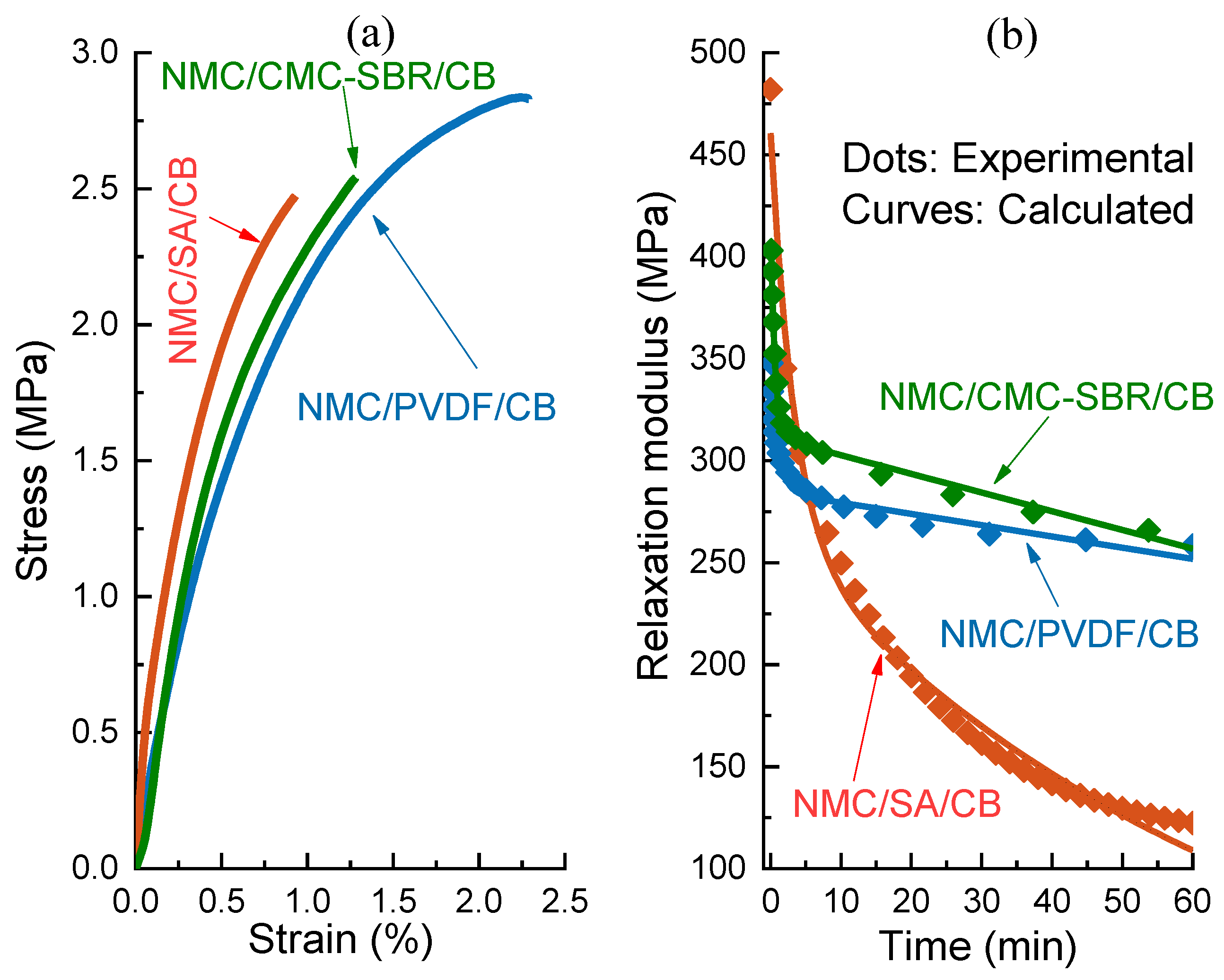
2.3. Mechanical Properties Measurement

To investigate the effect of drying temperature on the tensile strength of electrode coating, CMC (CMC 2200, Daicel, Japan)/SBR (BM450, Zeon, Japan), sodium alginate (SA) (Aladdin, Shanghai, China), and PVDF (Aladdin, Shanghai, China) were used as three types of polymer binders. The corresponding solvents are deionized water and N-Methyl-2-pyrrolidone (NMP). Meanwhile, LiNi0.5Mn0.3Co0.2O2 (NMC532, Kejing, Shenzhen, China) and carbon black (CB, CM65, Kejing, Shenzhen, China) were used as the active material and conductive agent, respectively. The slurries were prepared in two steps. Firstly, NMC particles and carbon black were mixed by a planetary mixer at a stirrer speed 400 rpm for 60 min, then binder–solvent solutions were added and stirred at a rate of 800 rpm for two hours. The obtained slurries were coated and dried in a lab-scale convective coater/dryer combination on the PTFE plate instead of metal current collects. Therefore, the dried coating films can be easily peeled off for the subsequent mechanical property tests. The drying nozzle velocity of flow airflow was kept constant at 17 m/s to acquire a continuous heat transfer coefficient of 46   W / ( m 2 K ) . And slurries were dried at 60 , 90 , 120 , 150 and 180 , respectively. All the dried films (90 wt% NMC532, 5 wt% carbon black, and 5 wt% polymer binder) were cut into rectangular samples with dimensions of 25 mm (L) × 6 mm (W) × 0.08 mm (T). The mechanical measurements were carried out at a strain rate of 5 × 10 3   s 1 at the room temperature of 25 °C, the humidity of 5% RH by a film/fiber tension clamp on a DMA (TAQ800, TA Instruments-Waters LLC, New Castle, DE, USA) with a DMA-RH accessory.
Moreover, to check the validity of the critical steps of the present method, the evolution of Young’s modulus of dried composite films was also measured by DMA and its RH accessory. After completely drying at 60 °C, NMC/SA/CB, NMC/CMC-SBR/CB, and NMC/PVDF /CB and PVDF/CB films were used for tensile stress relaxation at the constant strain levels of 0.2%, 0.3%, and 0.5%, respectively, which were chosen from the linear section of the related stress–strain curves of these composites. All the tests were kept to 60 min and had a sampling rate of 10 Hz.

3. Results and Discussion

To verify Equation (7) for effective properties of electrode composites, the predicted relaxation modulus of cathode coating films was compared to experimental results, which were obtained by the above stress relaxation of dried NMC/SA/CB, NMC/CMC-SBR/CB, and NMC/PVDF/CB films. The elastic modulus of carbon black (CB) was 32.47 GPa [34], and the elastic modulus of NMC particles was 175 GPa [35]. Their Poisson’s ratio was assumed to be 0.3. The measured relaxation modulus of PVDF/CB was fitted with the Prony series in Equation (4). The relaxation data of aqueous polymer (i.e., CMC-SBR, SA) with CB can be acquired by our previous report [36]. Figure 2a shows the uniaxial tensile behavior of NMC cathode composites with different binders dried at 60 °C. It is easy to observe that the engineering stress–strain curves exhibit the small-deformation characteristics of the brittle polymers, which broke after yielding without a cold drawing, and the elongation at break was less than 2.5% for all of the testing samples. Thus, the above continuum theory based on the small strain hypothesis is reasonable to determine the drying stress of electrode composites. Further, the applied strain values of 0.2%, 0.3%, and 0.5% would be in the linear viscoelastic range during stress relaxation of NMC based composite films containing SA, CMC-SBR, and PVDF, respectively. The corresponding relaxation modulus versus time is indicated in Figure 2b. All curves reveal typical viscoelastic behavior but with different degrees of reduction, which demonstrates that the polymer types played an essential role in the relaxation process. In particular, Young’s modulus of NMC/SA/CB steeply decreased up to about 20% of the initial value (t = 0) after 60 min. Such behavior may be attributed to remarkable modulus relaxation of SA/CB components [36]. It is noticed that there is good agreement between the calculated relaxation modulus and our experimental data. Therefore, the present micromechanical model based on modified MTM can describe the viscoelastic properties of electrode composites.

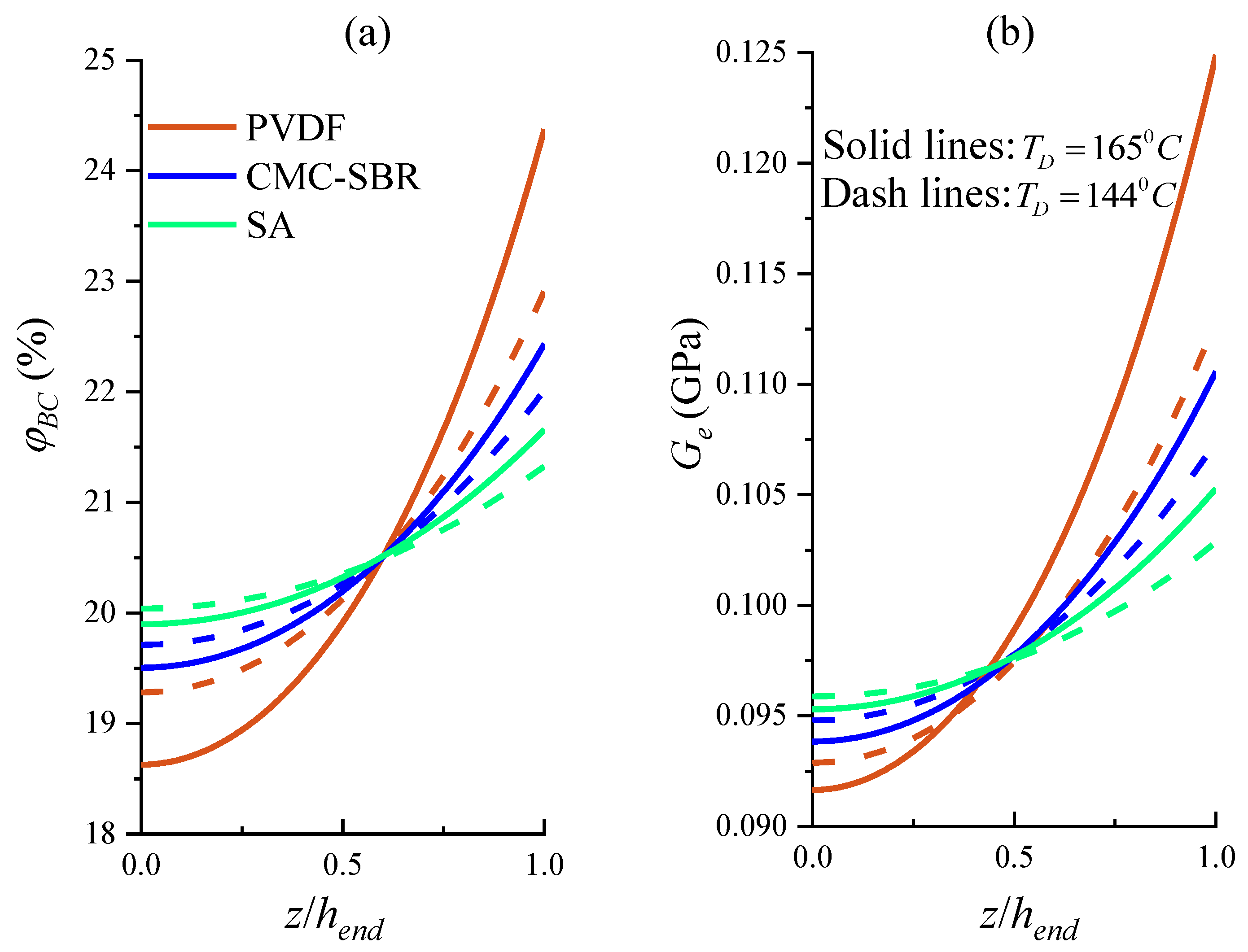
3.1. Gradient Distributed Physical Properties across Electrode Thickness

Although the tensile measurement of the slurry coating or the cantilever deflection [14] of the composite electrode can obtain the average elastic modulus of electrode composite, it is hard to determine the gradient distributed physical properties during the drying process. Firstly, regarding that, the electrode slurry is composed of the polymer binder (PVDF), conductive black (CB), and organic solvent (NMP). The mass density of PVDF, NMP, and the apparent density of CB are 1.76 g/cm3, 1.03 g/cm3 [12], and 0.2 g/cm3 [37], respectively. According to the report of Font et al. [12], the initial concentration c B C 0 , molar mass M B C , and diffusion coefficient D P V D F of BC are 0.057 mol/m3, 1000 kg/mol, and 1.14 × 10 10 m 2 s , respectively. The enthalpy of vaporization Δ h v and heat transfer coefficient α m of NMP are 513 kJ/kg [38] and 46   W / ( m 2 × K ) [21], respectively. As stated in Reference [12], the volume fraction of active material (NMC) at the beginning and end of drying was 0.28 and 0.5, respectively. We assume that the initial thickness of electrode slurry was 114 μ m [19]. Note that the drying temperature T D and nozzle speed v may be respectively set as 144 °C and 17 m/s according to the published work [21]. In terms of solving the moving boundary value problem of the partial differential equation and micromechanical model, the volume fraction of BC and shear modulus of NMC based composite under different times is shown in Figure 3.
Notably, the thickness of electrode slurry decreases with an increased drying time in Figure 3. To further probe the drying process, we plotted the volume fraction and effective shear modulus during the drying stage. Interestingly, after solvent evaporation for a longer time, the simulated concentration and volume fractions of BC increase until the dried thickness h ( t ) reaches a certain threshold 0.56 h 0 . This is consistent with the other experimental studies [5]. At the end of the drying operation, the distribution is greatly inhomogeneous, as shown in Figure 3 (i.e., the top line). Consequently, the drying process greatly influences the distribution of BC and shear modulus of the corresponding electrode composites.
Because organic solvents are generally environmentally unfriendly and combustible, safety issues and high costs are associated with their use in LIBs production, especially for electric vehicles. Therefore, water-based binders have been proposed as a new substitute, such as CMC-SBR [39] and SA [40]. In an isotropic medium, the Stokes–Einstein equation D B i n d e r = k T / 3 π μ d can be developed to predict the effective diffusion coefficient, where μ   is the viscosity of slurries, k T is thermal energy, and d is the effective diameter of BC. Consider the relation of the viscosity between CMC [41], SA [42], and PVDF [43] at a zero-shear state, we estimate that the diffusion coefficient of BC in the CMC-SBR slurry and SA slurry is 3 D P V D F and 10 D P V D F . Based on the tensile experimental data of SA and CMC-SBR [36], the enthalpy of vaporization of water 2257 kJ/kg [38], we compared the binder distribution and shear modulus of dried electrode films composed of PVDF, CMC-SBR, and SA, respectively, as seen in Figure 4. Upon completion of the drying process, solvents were removed from the slurry surface, which drove polymer binders and conductive additives to the coating surface [12], resulting in the heterogeneity of electrode composite in Figure 4. The electrode composite with organic solvent-soluble binders (i.e., PVDF), φ B C , and G e exhibit a less uniform distribution than that with aqueous polymer (i.e., CMC-SBR, SA). This is reasonable because the higher diffusion coefficient of water-based binders may compensate the BC gradient effect in the electrode slurries. Such a distributed trend is also qualitatively in accord with the result reported by Li et al. [7] in the study of the binder distributions of aqueous polymer-based and organic-based cathode sheets. Therefore, we may capture the internal stress variation in electrode composite during drying in the following section.

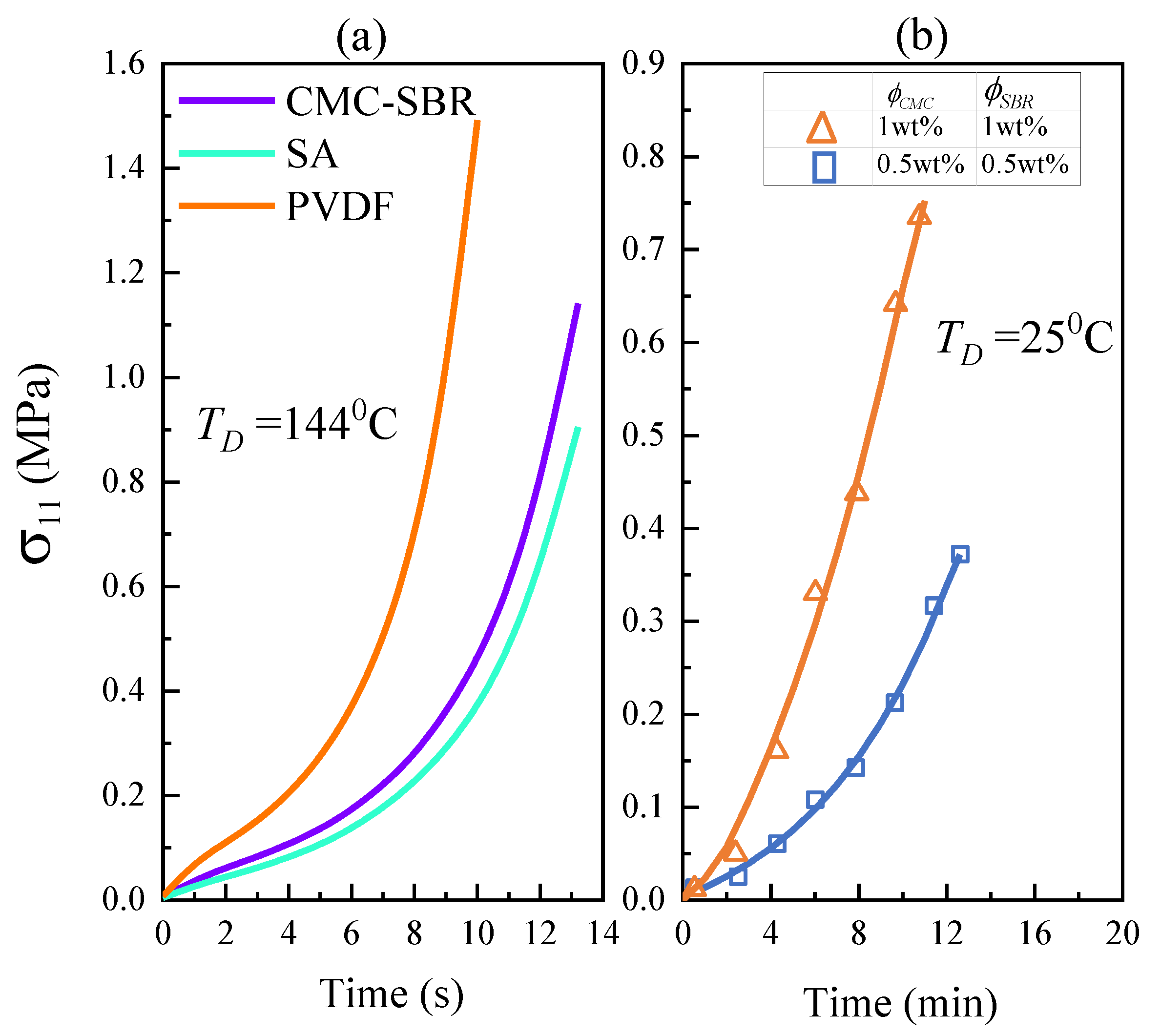
3.2. Evolution of Internal Stress Distribution during the Drying Process

Due to the constraint of the current collector, the biaxial internal stress in the coated layer would be induced during the drying process of electrode slurry, and the stress level can control the dried film integrity. Therefore, it is necessary to explore the evolution of drying stress against the solidification time and the stress distribution of the drying coating films, which is difficult to be determined by existing experimental methods. However, the mechanical integrity of slurry coating really depends on the peak stress at the position in electrode composite rather than the average stress of the material. We conducted a simulation on the drying-induced internal stress in the NMC electrode slurries based on the above-stated continuum model. To calculate the drying stress, the number of neighbors in contact to immobilize close-packed spheres,   M , was assigned a value of 5 [44]. The surface tension γ R can be calculated by γ R / γ s = 0.2 [45], where   γ s is the surface tension of solvent/air interface. Additionally, the surface tension of water and NMP are 72.8 mN/m and 40.8 mN/m [46], respectively. Therefore, according to Equations (6) and (8), we can obtain the internal stress at the coating surface in the drying step for NMC based slurries, as seen in Figure 5a. To validate the present method, the elastic modulus of graphite particles is 15GPa [47], and the drying stress in graphite anode slurries with CMC-SBR is also calculated as shown in Figure 5b. It can be found that the stress magnitude increases slowly during the initial stages of the drying process for NMC-based or graphite-based electrode slurries. This phenomenon is attributed to the fact that the liquid domain played a dominant role in this period. As expected, NMC/PVDF slurry exhibits a higher rate of stress growth than that with aqueous polymer binders due to the stiffer polymer networks. Furthermore, Figure 5b shows that the predicted drying stress in graphite/CMC-SBR/CB is in good accord with the experimental values [14]. Consequently, we have well captured the stress evolution for the drying electrode films using the constitutive relationship and incorporating the drying effect.
Following that, to identify the internal stress distribution of dried electrode coating, we consider the dried NMC based composites with three different polymer binders (CMC-SBR, SA, and PVDF). It is demonstrated in Figure 6 that the drying stress in coating exhibits non-uniform distribution typically along with the electrode thickness due to the composite heterogeneity. The peak stress appears at the electrode surface and is obviously larger than drying stress at the coating and current collector interface. The stress ratio of these two positions is 138.6%, 155.7%, and 177.9% for SA, CMC/SBR, and PVDF-based NMC cathode, respectively. It is ascribed that the heterogeneously distributed BC determines the elastic properties of electrode composite and leads to the gradient in effective modulus, which is the most significant for NMC/PVDF/CB, as seen in Figure 3. The aqueous polymer binder-based electrode composites have lower drying stress than that containing PVDF, which can also be explained by Figure 3 compared to the shear modulus.

3.3. Dependence of Mechanical Integrity on Drying Temperature

Understanding the effect mechanism of drying temperature on the mechanical integrity of the electrode coat during solidification is the crucial step in controlling this natural process. Firstly, the evolution of the tensile strength of NMC based composite films dried at the temperature ranging from 60 °C to 180 °C is shown in Figure 7. As T D increases, the tensile strength σ b would significantly decrease, which may be attributed to the initiation of many microcracks induced by thermal stress. It is noticed that dried NMC/PVDF/CB film exhibits the highest σ b value when the drying temperature of electrode slurry is below 130 °C. However, when drying temperature T D > 130 °C, NMC/SA/CB reveals better mechanical properties than NMC composites with the other two binders. Moreover, the NMC/CMC-SBR/CB system shows the lowest strength at almost all drying temperatures due to the unsatisfied heat resistance of SBR [48,49].
Secondly, we further discuss the mechanical integrity of the dried NMC coating films versus different drying temperatures, polymer binders, and their concentration in terms of the ratio of peak drying stress to tensile strength ( σ 11 P e a k / σ b ) as follows.
The variation in σ 11 P e a k / σ b with different drying temperatures (95–170 °C) for the NMC electrode coatings with 5 wt% CMC-SBR, 5 wt% SA, and 5 wt% PVDF, respectively, has been calculated as indicated in Figure 8. We find that the magnitude of σ 11 P e a k / σ b is increased at least 4 times as the drying temperature ( T D ) rises from 95 °C to 170 °C. Meanwhile, with an incremental T D , the stress would grow nonlinearly for all three types of electrode composites. It is reasonable because the higher drying temperature accelerates the migration degree of binders, leading to relatively significant heterogeneity of electrode slurry. The capillary stress is practically enhanced under the high-temperature condition, making the solvent migrate quickly to the surface and promote an evident gradient distribution of inactive materials. Furthermore, the mechanical integrity of dried PVDF system is more significantly dependent upon drying temperature than two kinds of aqueous polymer binder-based electrodes. This trend can be attributed to a less uniform distribution of binders in PVDF-based coating than water-based electrode slurry. Meanwhile, NMC/PVDF/CB also exhibits smaller stress than CMC-SBR and SA-based slurry at relatively lower drying temperatures. However, the opposite is true at higher drying temperatures ( T D 105 °C). In other words, PVDF has higher residual stress for electrode dried at a high temperature. Furthermore, the mechanical failure would occur in NMC/PVDF/CB and NMC/CMC-SBR/CB films after dried at T D 160 °C and T D 166 °C, respectively. Hence, when the slurry is dried at a relatively higher temperature, we may infer that the highest-to-lowest ranking of typical polymer binders for the electrode structure stability is: SA > CMC-SBR > PVDF, which has been verified from several previous studies [40,50,51].
As mentioned above, the mechanical integrity of the dried electrode coating is dependent on the binder type. It is also necessary to deliberate the effect of binder concentration in the NMC electrode slurry, as indicated in Figure 9. For the coating film contained SA, CMC-SBR, or PVDF, a higher mass fraction of binder can lower peak stress regardless of the drying temperature. That makes sense because more binder addition decreases the effective modulus of electrode composite. Therefore, the mechanical completeness of electrode slurry during the solidification process is closely related to the binder content and drying temperature. To keep the model simple and computationally tractable, we assume that the rheology of slurry does not change with the regular binder content (i.e., 0.5~5 wt%). To demonstrate the combined effects of the two critical factors and obtain the optimized values for engineering purposes, a set of simulations were accomplished with the results depicted in Figure 9. With the help of tensile strength σ b in Figure 7, the above 2D map is divided into two regions by a blue curve, i.e., a safe region I that reaches the resistance to mechanical failure of dried electrode coating can be obtained as depicted in the right area of Figure 9. It is found that the coating containing SA has the largest safe region, PVDF followed. At the same time, CMC-SBR based composite would be prone to mechanical damage under the higher drying temperature and lower binder content condition. It means that the composite electrode with CMC-SBR would face the significant challenges of improving production efficiency and energy density. These results provide essential insight into controlling the integrity degradation of electrode material during the drying operation.

4. Conclusions

Considering the migration of binders and conductive agents in the electrode slurry during solidification, a continuum mechanics model was developed to explore the component distribution, mechanical properties, and internal stress of the drying composite coating. Moreover, the effects of drying temperature and binder type on the peak stress and viscoelastic behavior of dried electrode composite were systematically investigated by simulation and mechanical measurement, respectively. The main conclusions are as follows.
(1)
The proposed model could reveal the gradient distributed inactive ingredients (binder and conductive agent, BC) across the electrode coating thickness. The calculated relaxation modulus of dried electrode composites is in good agreement with our experimental results. Noticeably, the predicted drying stress regarding the effect of interfacial tension in good accord with the reported test data.
(2)
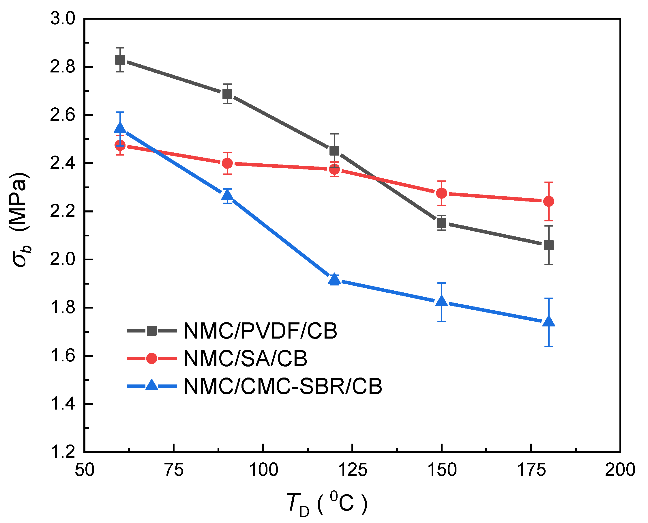
Higher drying temperature accelerates the inhomogeneity of BC distribution in electrode composite under the drying process, leading to the significant increase in internal stress of the electrode and significantly impairing the tensile strength of electrode composite. It is also found that the PVDF system exhibits more marked drying temperature dependence.
(3)
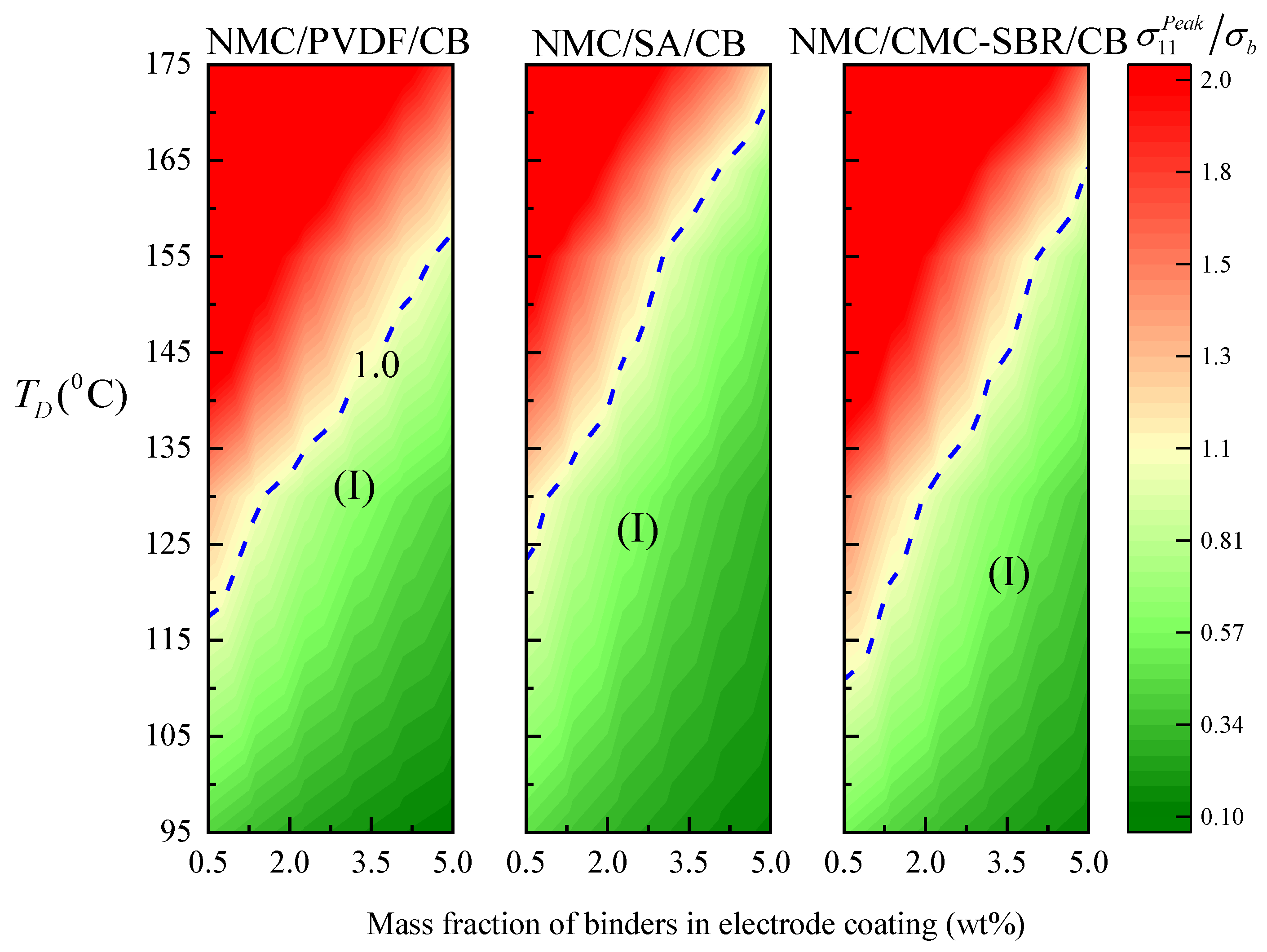
Increasing the binder content can decrease the effective modulus of electrode composite, thus reducing the peak drying stress regardless of the processing temperature.
Compared to PVDF and CMC-SBR, SA is more suitable for the rapid solidification of electrode composite. Adding 5 wt% could void the mechanical damage of NMC-based cathode dried under the ultra-high temperature condition ( T D = 170 °C).

Author Contributions

Conceptualization, H.H. and Y.H.; methodology, Z.Z.; software, Z.Z.; validation, H.H., Y.H. and F.Z.; formal analysis, H.H.; investigation, Z.Z.; resources, H.H.; data curation, H.H.; writing—original draft preparation, Z.Z.; writing—review and editing, H.H.; visualization, Z.Z.; supervision, H.H.; project administration, Y.H.; funding acquisition, H.H. All authors have read and agreed to the published version of the manuscript.

Funding

This research was funded by the National Natural Science Foundation of China under grant numbers 11872235, 11472164, and 11332005, as well as the National Basic Research Program of China (2014CB046203).

Institutional Review Board Statement

Not applicable.

Informed Consent Statement

Not applicable.

Data Availability Statement

Not applicable.

Conflicts of Interest

The authors declare no conflict of interest.

References

  1. Armand, M.; Tarascon, J.M. Building better batteries. Nature 2008, 451, 652–657. [Google Scholar] [CrossRef] [PubMed]
  2. Kwade, A.; Haselrieder, W.; Leithoff, R.; Modlinger, A.; Dietrich, F.; Droeder, K. Current status and challenges for automotive battery production technologies. Nat. Energy 2018, 3, 290–300. [Google Scholar] [CrossRef]
  3. Wang, Y.; Sahadeo, E.; Rubloff, G.; Lin, C.-F.; Lee, S.B. High-capacity lithium sulfur battery and beyond: A review of metal anode protection layers and perspective of solid-state electrolytes. J. Mater. Sci. 2019, 54, 3671–3693. [Google Scholar] [CrossRef]
  4. Rollag, K.; Juarez-Robles, D.; Du, Z.; Wood, D.L.; Mukherjee, P.P. Drying Temperature and Capillarity-Driven Crack Formation in Aqueous Processing of Li-Ion Battery Electrodes. ACS Appl. Energy Mater. 2019, 2, 4464–4476. [Google Scholar] [CrossRef]
  5. Jaiser, S.; Müller, M.; Baunach, M.; Bauer, W.; Scharfer, P.; Schabel, W. Investigation of film solidification and binder migration during drying of Li-Ion battery anodes. J. Power Sources 2016, 318, 210–219. [Google Scholar] [CrossRef]
  6. Du, Z.; Rollag, K.; Li, J.; An, S.; Wood, M.; Sheng, Y.; Mukherjee, P.; Daniel, C.; Wood, D. Enabling aqueous processing for crack-free thick electrodes. J. Power Sources 2017, 354, 200–206. [Google Scholar] [CrossRef] [Green Version]
  7. Li, C.-C.; Wang, Y.-W. Binder Distributions in Water-Based and Organic-Based LiCoO2 Electrode Sheets and Their Effects on Cell Performance. J. Electrochem. Soc. 2011, 158, A1361–A1370. [Google Scholar] [CrossRef]
  8. Porcher, W.; Lestriez, B.; Jouanneau, S.; Guyomard, D. Design of Aqueous Processed Thick LiFePO[sub 4] Composite Electrodes for High-Energy Lithium Battery. J. Electrochem. Soc. 2009, 156, A133–A144. [Google Scholar] [CrossRef]
  9. Lee, J.-H.; Kim, J.-S.; Kim, Y.C.; Zang, D.S.; Paik, U. Dispersion properties of aqueous-based LiFePO4 pastes and their electrochemical performance for lithium batteries. Ultramicroscopy 2008, 108, 1256–1259. [Google Scholar] [CrossRef]
  10. Müller, M.; Pfaffmann, L.; Jaiser, S.; Baunach, M.; Trouillet, V.; Scheiba, F.; Scharfer, P.; Schabel, W.; Bauer, W. Investigation of binder distribution in graphite anodes for lithium-ion batteries. J. Power Sources 2017, 340, 1–5. [Google Scholar] [CrossRef]
  11. Morasch, R.; Landesfeind, J.; Suthar, B.; Gasteiger, H.A. Detection of Binder Gradients Using Impedance Spectroscopy and Their Influence on the Tortuosity of Li-Ion Battery Graphite Electrodes. J. Electrochem. Soc. 2018, 165, A3459–A3467. [Google Scholar] [CrossRef]
  12. Font, F.; Protas, B.; Richardson, G.; Foster, J. Binder migration during drying of lithium-ion battery electrodes: Modelling and comparison to experiment. J. Power Sources 2018, 393, 177–185. [Google Scholar] [CrossRef] [Green Version]
  13. Baunach, M.; Jaiser, S.; Schmelzle, S.; Nirschl, H.; Scharfer, P.; Schabel, W. Delamination behavior of lithium-ion battery anodes: Influence of drying temperature during electrode processing. Dry. Technol. 2016, 34, 462–473. [Google Scholar] [CrossRef]
  14. Lim, S.; Kim, S.; Ahn, K.H.; Lee, S.J. Stress Development of Li-Ion Battery Anode Slurries during the Drying Process. Ind. Eng. Chem. Res. 2015, 54, 6146–6155. [Google Scholar] [CrossRef]
  15. Kumberg, J.; Müller, M.; Diehm, R.; Spiegel, S.; Wachsmann, C.; Bauer, W.; Scharfer, P.; Schabel, W. Drying of Lithium-Ion Battery Anodes for Use in High-Energy Cells: Influence of Electrode Thickness on Drying Time, Adhesion, and Crack Formation. Energy Technol. 2019, 7. [Google Scholar] [CrossRef]
  16. Li, J.; Rulison, C.; Kiggans, J.; Daniel, C.; Wood, D.L. Superior Performance of LiFePO4Aqueous Dispersions via Corona Treatment and Surface Energy Optimization. J. Electrochem. Soc. 2012, 159, A1152–A1157. [Google Scholar] [CrossRef]
  17. Davoodabadi, A.; Li, J.; Liang, Y.; Wang, R.; Zhou, H.; Wood, D.L.; Singler, T.J.; Jin, C. Characterization of Surface Free Energy of Composite Electrodes for Lithium-Ion Batteries. J. Electrochem. Soc. 2018, 165, A2493–A2501. [Google Scholar] [CrossRef]
  18. Forouzan, M.M.; Chao, C.-W.; Bustamante, D.; Mazzeo, B.A.; Wheeler, D.R. Experiment and simulation of the fabrication process of lithium-ion battery cathodes for determining microstructure and mechanical properties. J. Power Sources 2016, 312, 172–183. [Google Scholar] [CrossRef] [Green Version]
  19. Jaiser, S.; Kumberg, J.; Klaver, J.; Urai, J.L.; Schabel, W.; Schmatz, J.; Scharfer, P. Microstructure formation of lithium-ion battery electrodes during drying—An ex-situ study using cryogenic broad ion beam slope-cutting and scanning electron microscopy (Cryo-BIB-SEM). J. Power Sources 2017, 345, 97–107. [Google Scholar] [CrossRef]
  20. Malcolm Stein, I.V.; Aashutosh Mistry, P.P.M. Mechanistic Understanding of the Role of Evaporation in Electrode Processing. J. Electrochem. Soc. 2017, 164, A1616–A1627. [Google Scholar] [CrossRef] [Green Version]
  21. Westphal, B.G.; Kwade, A. Critical electrode properties and drying conditions causing component segregation in graphitic anodes for lithium-ion batteries. J. Energy Storage 2018, 18, 509–517. [Google Scholar] [CrossRef]
  22. Chen, Z.; Christensen, L.; Dahn, J.R. Mechanical and electrical properties of poly(vinylidene fluoride-tetrafluoroethylene-propylene)/Super-S carbon black swelled in liquid solvent as an electrode binder for lithium-ion batteries. J. Appl. Polym. Sci. 2004, 91, 2958–2965. [Google Scholar] [CrossRef]
  23. Christensen, R.; Lo, K. Solutions for effective shear properties in three phase sphere and cylinder models. J. Mech. Phys. Solids 1979, 27, 315–330. [Google Scholar] [CrossRef]
  24. Mori, T.; Tanaka, K. Average stress in matrix and average elastic energy of materials with misfitting inclusions. Acta Met. 1973, 21, 571–574. [Google Scholar] [CrossRef]
  25. McLaughlin, R. A study of the differential scheme for composite materials. Int. J. Eng. Sci. 1977, 15, 237–244. [Google Scholar] [CrossRef]
  26. Chen, J.-K.; Wang, W.-C.; Huang, Z.-P. Surface Energy Effect on Damage Evolution in a Viscoelastic Nanocomposite. Int. J. Damage Mech. 2010, 19, 949–970. [Google Scholar] [CrossRef]
  27. Li, D.; Hu, G.-K. Effective viscoelastic behavior of particulate polymer composites at finite concentration. Appl. Math. Mech. 2007, 28, 297–307. [Google Scholar] [CrossRef]
  28. Duan, H.; Wang, J.; Huang, Z.; Karihaloo, B. Size-dependent effective elastic constants of solids containing nano-inhomogeneities with interface stress. J. Mech. Phys. Solids 2005, 53, 1574–1596. [Google Scholar] [CrossRef]
  29. Madsen, B.; Thygesen, A.; Lilholt, H. Plant fibre composites—Porosity and stiffness. Compos. Sci. Technol. 2009, 69, 1057–1069. [Google Scholar] [CrossRef]
  30. Jones, E.M.C.; Silberstein, M.N.; White, S.R.; Sottos, N.R. In Situ Measurements of Strains in Composite Battery Electrodes during Electrochemical Cycling. Exp. Mech. 2014, 54, 971–985. [Google Scholar] [CrossRef]
  31. Huang, Z.P.; Sun, L. Size-dependent effective properties of a heterogeneous material with interface energy effect: From finite deformation theory to infinitesimal strain analysis. Acta Mech. 2006, 190, 151–163. [Google Scholar] [CrossRef]
  32. Tirumkudulu, M.S.; Russel, W.B. Role of Capillary Stresses in Film Formation. Langmuir 2004, 20, 2947–2961. [Google Scholar] [CrossRef]
  33. Tirumkudulu, M.S.; Russel, W.B. Cracking in Drying Latex Films. Langmuir 2005, 21, 4938–4948. [Google Scholar] [CrossRef]
  34. Qi, Y.; Guo, H.; Hector, L.G., Jr.; Timmons, A. Threefold Increase in the Young’s Modulus of Graphite Negative Electrode during Lithium Intercalation. J. Electrochem. Soc. 2010, 157, A558–A566. [Google Scholar] [CrossRef]
  35. Sun, H.; Zhao, K. Electronic Structure and Comparative Properties of LiNixMnyCozO2 Cathode Materials. J. Phys. Chem. C 2017, 121, 6002–6010. [Google Scholar] [CrossRef]
  36. Hu, H.; Tao, B.; He, Y.; Zhou, S. Effect of Conductive Carbon Black on Mechanical Properties of Aqueous Polymer Binders for Secondary Battery Electrode. Polymers 2019, 11, 1500. [Google Scholar] [CrossRef] [Green Version]
  37. Zaghib, K.; Shim, J.; Guerfi, A.; Charest, P.; Striebel, K. Effect of Carbon Source as Additives in LiFePO4 as Positive Electrode for Lithium-Ion Batteries. Electrochem. Solid-State Lett. 2005, 8, A207–A210. [Google Scholar] [CrossRef]
  38. Susarla, N.; Ahmed, S.; Dees, D.W. Modeling and analysis of solvent removal during Li-ion battery electrode drying. J. Power Sources 2018, 378, 660–670. [Google Scholar] [CrossRef]
  39. Gordon, R.; Orias, R.; Willenbacher, N. Effect of carboxymethyl cellulose on the flow behavior of lithium-ion battery anode slurries and the electrical as well as mechanical properties of corresponding dry layers. J. Mater. Sci. 2020, 55, 15867–15881. [Google Scholar] [CrossRef]
  40. Ling, L.; Bai, Y.; Wang, Z.; Ni, Q.; Chen, G.; Zhou, Z.; Wu, C. Remarkable Effect of Sodium Alginate Aqueous Binder on Anatase TiO2 as High-Performance Anode in Sodium Ion Batteries. ACS Appl. Mater. Interfaces 2018, 10, 5560–5568. [Google Scholar] [CrossRef] [PubMed]
  41. Lim, S.; Ahn, K.H.; Yamamura, M. Latex Migration in Battery Slurries during Drying. Langmuir 2013, 29, 8233–8244. [Google Scholar] [CrossRef]
  42. Dodero, A.; Vicini, S.; Alloisio, M.; Castellano, M. Sodium alginate solutions: Correlation between rheological properties and spinnability. J. Mater. Sci. 2019, 54, 8034–8046. [Google Scholar] [CrossRef]
  43. Sung, S.H.; Kim, S.; Park, J.H.; Park, J.D.; Ahn, K.H. Role of PVDF in Rheology and Microstructure of NCM Cathode Slurries for Lithium-Ion Battery. Materials 2020, 13, 4544. [Google Scholar] [CrossRef] [PubMed]
  44. Donev, A.; Cisse, I.; Sachs, D.; Variano, E.A.; Stillinger, F.H.; Connelly, R.; Torquato, S.; Chaikin, P.M. Improving the Density of Jammed Disordered Packings Using Ellipsoids. Science 2004, 303, 990–993. [Google Scholar] [CrossRef] [PubMed] [Green Version]
  45. Routh, A.F.; Russel, W.B. A Process Model for Latex Film Formation: Limiting Regimes for Individual Driving Forces. Langmuir 1999, 15, 7762–7773. [Google Scholar] [CrossRef]
  46. Sahore, R.; Wood, D.L.; Kukay, A.; Grady, K.M.; Li, J.; Belharouak, I. Towards Understanding of Cracking during Drying of Thick Aqueous-Processed LiNi0.8Mn0.1Co0.1O2 Cathodes. ACS Sustain. Chem. Eng. 2020, 8, 3162–3169. [Google Scholar] [CrossRef]
  47. Christensen, J.; Newman, J. Stress generation and fracture in lithium insertion materials. J. Solid State Electrochem. 2006, 10, 293–319. [Google Scholar] [CrossRef]
  48. Mostafa, A.; Abouel-Kasem, A.; Bayoumi, M.; El-Sebaie, M. The influence of CB loading on thermal aging resistance of SBR and NBR rubber compounds under different aging temperature. Mater. Des. 2009, 30, 791–795. [Google Scholar] [CrossRef]
  49. Rezig, N.; Bellahcene, T.; Aberkane, M.; Abdelaziz, M.N. Thermo-oxidative ageing of a SBR rubber: Effects on mechanical and chemical properties. J. Polym. Res. 2020, 27, 1–13. [Google Scholar] [CrossRef]
  50. Kovalenko, I.; Zdyrko, B.; Magasinski, A.; Hertzberg, B.; Milicev, Z.; Burtovyy, R.; Luzinov, I.; Yushin, G. A Major Constituent of Brown Algae for Use in High-Capacity Li-Ion Batteries. Science 2011, 334, 75–79. [Google Scholar] [CrossRef]
  51. Wang, Y.; Dang, D.; Li, D.; Hu, J.; Cheng, Y.-T. Influence of polymeric binders on mechanical properties and microstructure evolution of silicon composite electrodes during electrochemical cycling. J. Power Sources 2019, 425, 170–178. [Google Scholar] [CrossRef]
Figure 1. Illustration of a composite electrode film during drying process.
Energies 14 01683 g001
Figure 2. (a) Tensile stress–strain curves and (b) evolution of relaxation Young’s modulus for LiNi0.5Mn0.3Co0.2O2 (NMC)-based composite with different binders. CMC-SBR, carboxymethyl cellulose/styrene-butadiene rubber; CB, carbon black; PVDF, poly (vinylidene fluoride); SA, sodium alginate.
Energies 14 01683 g002
Figure 3. Concentration of (a) conductive additives (BC) and (b) effective shear modulus of NMC/PVDF/CB slurry across electrode thickness at different drying times.
Energies 14 01683 g003
Figure 4. (a) Volume fraction distribution, φ B C of BC and (b) shear modulus, G e of dried NMC based composite across electrode thickness.
Energies 14 01683 g004
Figure 5. Internal stress against drying time for (a) NMC electrode slurries (b) Graphite/CMC-SBR/CB slurries (curves: predicted, dots: experimental).
Energies 14 01683 g005
Figure 6. Internal stress distribution along with electrode coating thickness at the end of the drying process (a) NMC/PVDF/CB; (b) NMC/SA/CB; (c) NMC/CMC-SBR/CB.
Energies 14 01683 g006
Figure 7. Effect of drying temperature on tensile strength of dried NMC electrode composites.
Energies 14 01683 g007
Figure 8. Effect of drying temperature on mechanical integrity of dried electrode coating with different binders.
Energies 14 01683 g008
Figure 9. Effect of binder content in electrode composite on mechanical integrity of dried coating film.
Energies 14 01683 g009
Publisher’s Note: MDPI stays neutral with regard to jurisdictional claims in published maps and institutional affiliations.

