1. Introduction
Environment protection is currently one of the most important criteria used in the design and construction of the means of transport with internal combustion engines. Various energy efficiency and CO
2 emission criteria are also used in maritime transport, e.g., Energy Efficiency Design Index (EEDI), introduced by the International Maritime Organization (IMO) [
1,
2]. There has been research on practical implementation on these regulations into the design process of new built ships [
3]. The use of turbine engines for ship propulsion to obtain environmental advantages have been presented in [
4]. The paper presents ecological parameters’ comparison of turbine and piston engines. The energy characteristics of liquefied natural gas (LNG) carriers have been discussed in [
5]. The EEDI formula of LNG carriers was proposed on the ship EEDI formula.
The aim of the work presented in [
6] was to study the effect of using emission reduction strategies for container ships with emphasis on the improved energy efficiency.
These indexes apply to different types of transport vessels, while fishing vessels are not subject to these requirements. The International Convention for the Prevention of Pollution from Ships (MARPOL 73/78) in regulation 13 (IMO, 1973), defines NOx emission limits for marine internal combustion engines with power exceeding 130 kW. In practice, this means that the majority of medium and small fishing vessels, e.g., those operating within the Baltic Sea, are subject to this regulation.
Innovations and operational awareness of crews and ship operators in energy efficiency may continue to provide a spectrum of opportunities and solutions for implementing energy efficiency measures in their businesses. While for large, newly built ships, advanced measures to reduce harmful and greenhouse gas emissions are now widely undertaken, a fleet of small vessels (e.g., fishing) is still overlooked in this respect. It results from its investment dispersion and small budget possibilities of individual shipowners. Meanwhile, the number of such units is significant and the total amounts of emissions may reach large values.
It is difficult for many shipowners of fishing vessels and especially older ones to meet the NOx emission requirements applying to them. Replacement of old internal combustion engines with new ecological ones is often too expensive, while building new fishing boats is a too big of an investment, difficult to carry out with small and unpredictable profits from fishing. Therefore, other solutions are necessary. Such solutions, on the one hand, should reduce GHG emissions from fishing vessel engines and, on the other hand, the costs of these solutions should be acceptable to small, often family-run fishing enterprises.
A comprehensive analysis of barriers for adoption of energy efficiency operational measures in shipping industry is presented in [
7]. The objective of the work was to recognize the social barriers to energy efficiency measures implementation with the use of survey among various stakeholders from shipping industry. The research results are that the barriers are lack of information of the measure, lack of awareness and competence of ship crews and operation difficulties which are in nature of information and technical barriers. Financial issue and interest were recognized by the survey as key factors preventing more effective implementation [
7].
According to statistical data for the year 2018 [
8], 124 medium-size fishing vessels of up to 25 m in length were registered in Poland. The average age of these vessels is about 40 years [
8]. For these fishing vessels, if they are to stay in use, some solution should be proposed to reduce propulsion power, fuel consumption and GHG emissions. One such solution is a local modification of the fishing vessel hull shape by adding a bulbous bow. A bulbous bow is a protruding bulb at the bow (or front) of a ship just below the waterline. The bulb modifies the way the water flows around the hull and if properly designed should reduce drag. Specific flow conditions may be very different in many possible design combinations of ship’s hull and in-depth analyses are necessary to properly assess the feasibility of a particular design proposal.
First studies on hull shape variants which would result in resistance reduction date back to the 1930s. However, methodical research on local modifications of hull shape which mostly applies to bulbous bows, was presented by Alfred M. Kracht [
9]. In his publication he proposed a method for selecting the bulbous bow shape for ships characterized by low Froude number. On the basis of Kracht’s work, in 1986 the methodology for bulbous bow selection for fast ships (with high Froude number values) was presented in the paper by Hoyle et al. [
10]. The authors continue the research into bulbous bow shapes giving best results.
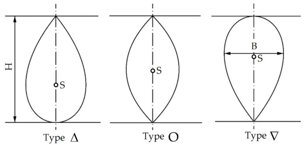
Figure 1 shows the idea of the classification of main variants of the bulbous bow shapes used until today. The quoted studies and the design guidelines contained therein, despite the passage of time, have not lost their relevance and can still be used for the conceptual design of ships. The final confirmation of the design guidelines included in the works [
9,
10] takes place during model tests in basins.
The last decade has seen a large increase in the computing power of computers, which has resulted in the development and spread of calculation-based approaches. For the shipbuilding industry, this has opened up new opportunities for research on the shapes of hulls by enabling numerical modelling of ship hull shapes featuring bulbous bows at an early phase of design process.
For this reason, bulbous bows, their shapes and the results that can be achieved this way have become the subject of numerous analyses. A review of contemporary studies has been carried out for small vessels as well as methods of modifying their shape in order to reduce resistance and thus propulsion power and fuel consumption. In case of large transport vessels, the problem of resistance reduction achievable by using bulbous bows is considered to be sufficiently well researched. For small vessels such as fishing vessels, however, bulbous bows are mostly used for new designs. However, there is a lack of systematic research for vessels that have been in operation for many years and are under analysis for retrofits.
In the works by Huang et al. [
11,
12], authors describe the method of selecting the bulbous bow basing on simplified and abstract shapes. They presented an algorithm that allows for the specification of a smoothly shaped bulbous bow for a large transport vessel using the objective function. In the above-mentioned works, there was no reference to the ease of manufacture related to the proposed shapes. This is a consequence of the assumption that the optimized hull shape will be built in the shipyard as a new vessel. The proposed algorithm can be useful at an early phase of design, as a supplement to software dedicated to the design of hull theoretical lines.
The shape of a fishing vessel with an added bulbous bow was calculated using numerical methods and presented in [
13]. Unlike the works [
11,
12], the calculations for a fishing vessel are presented. The obtained modified shape turned out to be smooth, which suggests that its application is aimed at new designs. The paper does not refer to the possibility of installing such a bulbous bow on an existing hull.
Another work dealing with the problem of selecting a bulbous bow for a fishing vessel is the publication by Blanchard et al. [
14]. In that work, the effect of a bulbous bow of smooth shape was examined with regard to one model of a fishing vessel at a given speed. The aim of the study was to create an algorithm which would allow the determination of the resistance with the added bulbous bow. The shape of the bulbous bow was optimized and the parameters were its width and length. No reference was made in this publication to the possibility of applying modifications during a retrofit of a fishing vessel. The smooth shape of the bulbous bow seen also in this case suggests that the algorithm is dedicated to the new design phase.
Some practical guidelines for the modification of a fishing vessel hull shape are contained in the publication of the UN Food and Agriculture Agency [
15]. This publication, having the form of a guide, is intended for developing countries. The issues discussed in it are related to the ways of reducing fuel consumption on small fishing vessels. Similarly to the suggestions resulting from the IMO Convention, the author of this study suggests the modernization of propulsion system. However, he pays special attention to the opportunities for the modification of the existing vessels. He presents the benefits of using bulbous bows and some general guidelines for their use. At the same time, he stresses that a well chosen bulbous bow can result in fuel savings of up to 15% compared to the hull without such a modification. Despite the recommendations for the use of bulbous bows and the emphasis placed on their advantages, there are no rough (approximate) formulae to help design a bulbous bow for a given type of hull. The author of the study points out that this type of modification should be carefully adopted to bring the expected effect. The paper suggests the need to develop templates useful for hull modernization, which could be used in workshop conditions. It is however difficult to assess if such templates, even if developed, would bring satisfying results for the entire range of various shapes and flow conditions.
There are presently no studies which contain any information on the effects obtained for the ships undergoing conversion. Current works and publications focus on the design of new fishing vessels and optimization of their shape. The resulting theoretical lines of the hull designed in this way are smooth and complex. In case of a fishing boat project built as new in the shipyard, obtaining smooth hull lines is not a problem. On the basis of a chosen case, we present here the proposal of the procedure on how to make use of modern computational fluid dynamics methods to the assessment of the possible modification of hull shape of existing vessels in operation. The expected results should allow for more formal analysis of the flow and further energy optimization of fishing vessels.
3. Research Method
An analysis of the effect of the added bulbous bow on the resistance of the fishing vessel can be carried out:
basing on experimental research in a model test basin,
by means of numerical simulations (calculation of fluid dynamics (CFD) method).
Since a modification of a fishing vessel has to be cheap and would be applied to vessels already in operation, the CFD (calculation fluid mechanics) method has been chosen as the test method. The analysis of the effect that the added bulbous bow has on vessel resistance was performed for the B-410 fishing vessel type (
Figure 2). The shape and the parameters of the additional bulbous bow are shown in
Figure 3. During the calculations the length of the bow bulb was altered and other parameters were kept constant. The technical and operational parameters of the B-410 fishing vessel are presented in
Table 1.
To evaluate the benefits achieved (reduction of propulsion power, fuel consumption, reduction of exhaust emissions), a computational research method was used, using the results of experimental measurements of the combustion engine installed on the tested fishing boat.
The action of the fluid on the hull of the vessel was determined using the RANS approach for an incompressible, turbulent flow with the free surface. The open source software OpenFOAM v8, The OpenFOAM Foundation, London [
17] was used to determine the flow around the hull and to calculate the hull resistance of a fishing vessel under consideration with added bulbous bows of different geometric parameters. The OpenFoam system is based on the libraries of codes for solving differential equations modelling the particular flow problem. For the considered case, the free surface deformations were modelled with the help of volume-of-fluid (VOF) method. Fishing vessels move through water at variable speeds. The Reynolds number Re, is high enough for the resulting flow around the hull to be turbulent. The model applied for turbulence modelling was the
k-ω model, as showing capabilities to accurately map the flow separation in the after part of the hull. A two-phase simulation was carried out in which both phases had their properties set as parameters for water and air (
Table 2). The simulation was pseudo-steady in time, the fluids did not mix and the hull grid remained stationary (zero degrees of freedom). The grid of elements (
Figure 4) was made of cubic type elements, while in the vicinity of the hull the elements change into polygonal type. The boundary layer of the grid was arranged in such a way as to obtain parameter
Y+ in range of 150–300. In order to keep the time needed to perform the simulation reasonable, the plane of symmetry of the tested vessel hull was applied. The overall dimensions of the grid are shown in
Table 2. The boundary conditions of the simulation process have been adopted to simulate a model testing basin with boundaries at infinity. The aim of this approach wasn to prevent artificial waves forming at the boundaries of the domain, which would interfere with the computed results. The types of boundary conditions used are shown in
Table 2.
The atmospheric conditions during the simulation were omitted to determine the effect of the bulbous bow on the total resistance. Omitting the effects of waves and wind represents the conditions of speed test on so called measuring mile. The values of design speed and trawling speed were adopted as those of the examined vessel type (
Table 1).
The 3D model of the examined fishing vessel and the vessel with the superimposed grid of elements are shown in
Figure 4, while the computation domain and the grid of elements are shown in
Figure 5.
Since there are no direct resistance measurements available for the modified fishing vessel, the numerical approach applied herein was tested for two models of other ships where model basin test results were available.
Validation of the results of the numerical calculation of ship’s resistance shall be carried out by comparing them with the results of the model basin tests. The calculated resistance values were compared with respective model basin experiment results, and the numerical computation method error did not exceed 3%—the obtained results are shown in
Table 3.
4. Results of Flow Computations
The total hull resistance
RT consists of two main components:
where:
—pressure resistance, consisting mainly of wave-making resistance. This component depends mostly on pressure distribution around a ship’s hull. In the presence of free surface (interface between the water–liquid and air–gas phases along a ship’s draft), the pressure distribution is responsible for generating the wave system that dissipates energy from the flow;
—viscous resistance which depends mainly on the wetted area of the hull.
Installation of the bulbous bow causes:
an increase of the wetted surface of the hull, and thus an increase of the viscous resistance,
reduction of pressure in the bow area, which reduces the wave-making resistance in relation to the ship’s hull without a bow bulb.
The influence of the bow bulb on the ship’s total resistance, if it is properly designed, can be illustrated as in
Figure 6. The components (
RW and
RV) of the total resistance are presented schematically in the function of Froude number, which is a dimensionless number used to quantify the influence of gravity on the motion of a fluid and represents the intensity of wave making resistance.
At low vessel speed (low Froude number
Fr), the added bulb may tend to increase the total resistance of the vessel
RT. In the range of speeds corresponding to the
Fr number from
Fr1 to
Fr2,
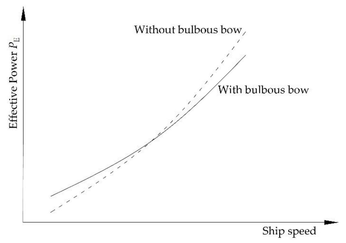
Figure 6, the impact of the bulbous bow on the ship’s resistance is negligibly small. The advantageous effect of the bow bulb is visible as soon as a certain value of the
Fr2 number is reached (or vessel speed
V), and as a result, the total drag, and thus the propulsion power, is reduced, e.g.,
PE—
Figure 7. More information on the general principles of the ideas behind the bulbous bow application can be found e.g. in the work of Molland [
19].
The influence of the bulbous bow on the reduction of the resistance and the propulsion power, according to e.g., [
19] mainly depends on:
the length of the bulb LB referenced from the fore perpendicular,
cross sectional area ABT of the section at the fore perpendicular,
the coordinate of the geometrical centre hB of the section measured from the base line,
the shape of the bulb in side view,
the geometry of the intersection line of the surface of bulb and the shape of the hull.
A simple bulb in the form of a cylinder with a lenticular section (type “O” bulb according to [
9] presented in
Figure 3) was used on the fishing boat. The bulb is directly connected to the existing hull of the fishing vessel under consideration. During numerical tests of the vessel’s resistance, only the length of the bulb
LB was altered, and all other geometrical parameters were not changed.
The resulting hull resistance RT depends, among others, on the length LB of the selected bulb (its surface) and on the fishing boat speed defined by the Froude number.
The calculation of hull resistance with the additional bulbous bow of O-type shape was carried for the actual size (full scale) of the fishing vessel, whose technical and operational parameters are shown in
Table 1. Modelling a flow at the full scale is more demanding from the grid requirements point of view but then no upscaling procedure is needed and there are no scaling errors. The design parameters adopted for the simulation of flow around the fishing vessel’s hull as well as resistance calculations are presented in
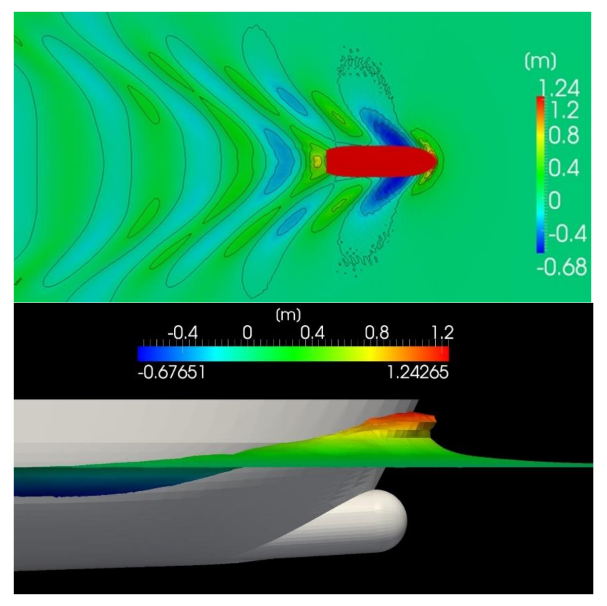
Table 2. Exemplary visualization of one of the calculation variants is presented in
Figure 8.
The calculations of the resistance RT of the fishing boat with the use CFD method have been carried out according to the following parameters:
fishing boat speeds V from 5 to 11 knots with the step of 0.5 knot,
different bulb lengths LB of the type “O” from 0.01 to 1.13% LWL with the step of 0.01% LWL.
The selected results of resistance calculations for various B-410 vessel speeds (
Figure 2) and the three bulbous bows of different lengths (
Figure 3) are presented in
Figure 9 and
Table 4.
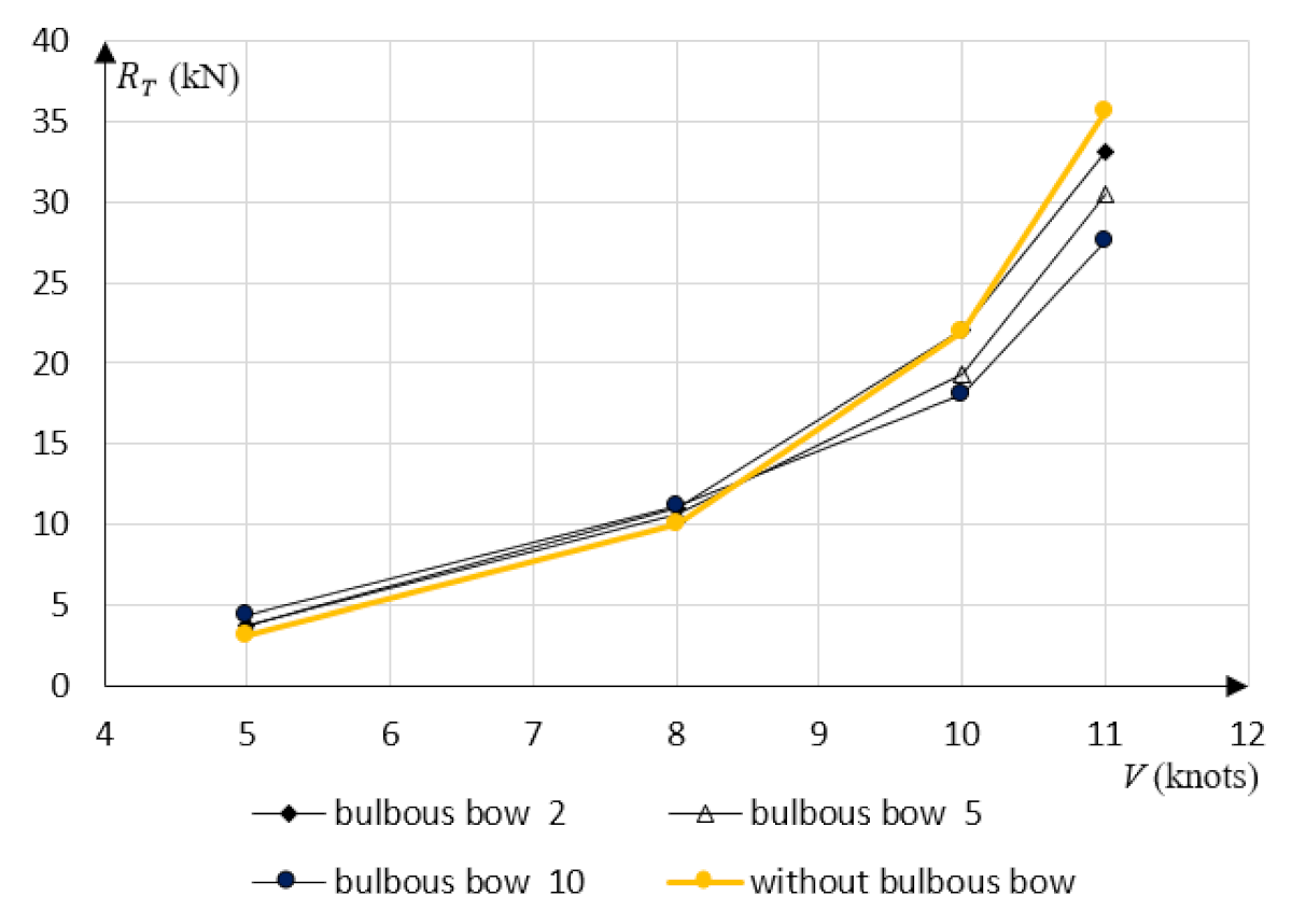
The length parameters of the bolbous bow presented in
Table 4 are as follows:
bulbous bow 2: LB(2) = 2% LWL = 0.486 m;
bulbous bow 5: LB(5) = 5% LWL = 1.215 m;
bulbous bow 10: LB(10) = 10% LWL = 2.430 m;
where: LB—length of bulbous.
The parameters in
Table 4 and results in
Figure 9 show that for low speeds of the fishing boat, adding a bulbous bow causes a small increase in the total resistance
RT, caused by an increase in the viscous resistance
RV. At higher speeds, adding a bow bulb is advantageous—there is a lower total resistance
RT because there is a lower wave making resistance
RW, compared to a fishing boat without a bulbous bow, which is in line with our expectations.
Figure 10 shows all the results of calculating the resistance of the fishing boat under consideration. In this figure, the curves (contours) represent the relationship:
Figure 10 shows data concerning the resistance values for a fishing vessel with additional bulbous bow (the whole range of fishing vessel speeds V as well as bulbous bow lengths
LB) in relation to resistance values for a fishing vessel without a bulbous bow. In this figure the contour lines with values smaller than 1.0 show the ranges of parameters V and
LB, for which there is a decrease in the resistance of a fishing vessel with a bulbous bow, while for values larger than 1.0 a corresponding increase in the resistance is noted.
5. Results of Calculated Fuel Consumption and Emissions Due to the Bulbous Bow Refitting
A SULZER 6AL 20/24 engine is used for the propulsion of the fishing vessel, driving a controllable pitch propeller via a reduction gearbox (
Table 1). Vessel speed is controlled by the changes of propeller pitch at a constant rotational speed of the engine and the propeller.
The propulsion power is calculated according to the formula:
where:
—effective power,
—propulsive efficiencies, accordingly: hull efficiency, open water propeller efficiency, rotational efficiency, shaft efficiency, gear efficiency,
—total propulsive efficiency of the entire propulsion system of the fishing boat, which for the considered case is
- -
for V = 11 knots,
- -
for V = 5 knot (at lower speeds, despite a controllable pitch propeller is used, its efficiency decreases).
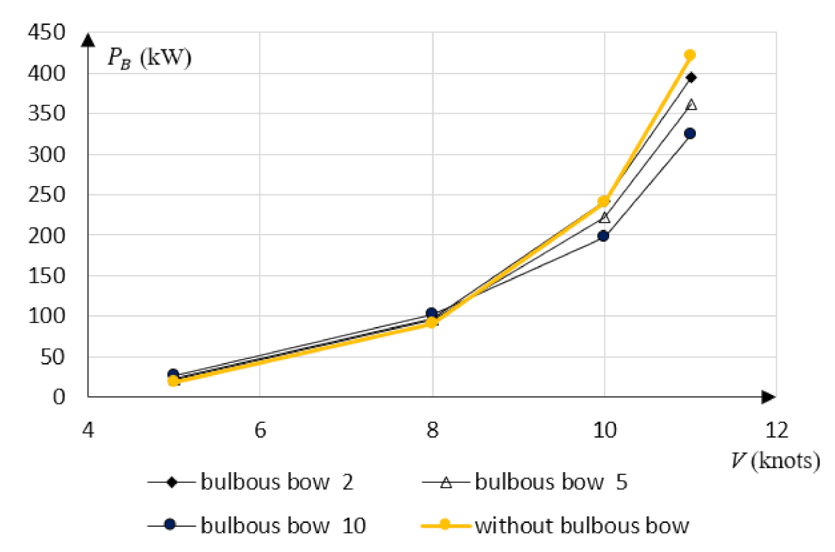
The results of power
PB calculations (engine loads) for different speeds
V and different bulbous bows 2, 5 and 10 are presented in
Figure 11.
The publication [
20] presents the results of operational measurements in service, including fuel consumption of the SULZER 6AL 20/24 engine for different engine load values. On the basis of these measurements, using an approximation, the fuel consumption was calculated for the engine load values presented in
Figure 11. The calculated fuel consumption and propulsion power are presented in
Table 5.
The publication [
4] presents the results of measurements of the amount and composition of the exhaust gases of the SULZER engine during tests on the experimental stand at various engine loads. Using the measurement results and using approximation methods, the amount and composition of exhaust gases were calculated for the engine load from
Figure 9. The results of the NOx, CO and CO
2 emissions calculations are presented in
Table 6,
Table 7 and
Table 8.
6. Analysis of the Results Obtained
The values of numerically calculated resistance of the fishing vessel hull with an additional bulbous bow shown in
Figure 10 show that resistance in relation to a vessel without a bulbous bow varies depending on the vessel speed
V and the length of the bulbous bow, e.g.,
for a bulbous bow of length higher than LB = 0.06 LWL, there is a reduction in resistance for the vessel speed exceeding 8.5 knots,
for lower speeds regardless of the relative length of the bulbous bow, there is a small increase in resistance—the bulbous bow increases slightly the wetted surface which in turn increases friction resistance dominating the flow at slower speeds.
The consequence of resistance changes are the changes in the propulsion engine load—the higher the vessel’s speed, the larger the difference between the engine loads for conventional and bulbous bow equipped vessels. It is a similar situation with fuel consumption and exhaust gas emissions—for higher vessel speeds the exhaust gas emissions are lower when compared to corresponding speeds without modification, which follows from lower fuel consumption.
The geometry of bulbous bow, in this case represented by its length, influences the reduction of fuel consumption and the exhaust gas emissions. Three bulbous bows have been adopted for the research, having lengths marked as 2, 5 and 10. The best effects were obtained for bow 10.
Table 5,
Table 6,
Table 7 and
Table 8 show the gains resulting from the reduction of fuel consumption and exhaust gas emissions on bulbous bow equipped vessels in comparison with conventional ones.
These gains, when calculated for an hour of vessel service, are not high in case of toxic exhaust gas components NOx and CO, however the reduction of CO2 GHG is significant. However, when this is done for the annual vessel service period while accounting for the whole fleet of vessels, the savings in fuel consumption and GHG emissions become very large.
Fishing vessels sail at various speeds and various draughts (deadweights) during a single fishing cycle (going to fishery, fishing, return to port with caught fish). The highest draught (resulting from caught fish weight) and the highest speed take place when the vessel returns to port.
In addition, the distance between fishery and an unloading port is important. In order to determine the average resistance, fuel consumption and exhaust gas emissions across the whole fishing cycle, various fishing cycles should be analysed to determine the distance from port to fishery at which the gains obtained through the installation of a bulbous bow are going to be significant in comparison with the existing conventional vessels.
The results of calculations of the average fuel consumption and exhaust gases emissions for an example fishing voyage cycle are presented in
Table 9. For the calculations, the parameters given in
Table 4,
Table 5,
Table 6,
Table 7 and
Table 8 were used.
The calculations of the averaged resistance
and the total fuel consumption and exhaust gas emissions were calculated according to the following formula:
in a similar way, according to formula (4) we calculate the total emission of NOx, CO, CO
2,
In order to assess the benefits of using a bulbous bow and to make a decision to modify a fishing boat, the following procedure should be executed:
developing an annual plan of fishing trips to different fisheries (distance from the fishing port),
making calculations for all possible cases—for some fishing trips adding a bow bulb will be beneficial, and for others it may not be beneficial due to fuel consumption,
calculation of the average annual value of fuel consumption for the boat with the bulbous bow and comparison with the same calculations for the boat without the bulbous bow,
estimation of the cost of modernization (adding a simple bow bulb, manufactured in workshop conditions),
comparison of the costs and profits in order to decide on the modernization of the boat.
The research on the effects that the additional bulbous bows have on existing vessels, and in particular the results of calculations presented in
Figure 10, can be used for the purpose of similarly modernizing vessels sailing in other waters—it is only necessary to prepare an appropriate fishing plan including a division into phases (time and speed of the vessel at a given phase of the voyage). Such calculations would allow for the assessment of economic benefits, and then to make a rational decision regarding the possible modernization of the vessel by the addition of a bulbous bow.


