Article

Feedback-Linearization-Based Fuel-Cell Adaptive-Control Paradigm in a Microgrid Using a Wavelet-Entrenched NeuroFuzzy Framework

1
Department of Electrical and Computer Engineering, COMSATS University Islamabad-Abbottabad Campus, Abbottabad 22060, Pakistan
2
Department of Electrical and Computer Engineering, COMSATS University Islamabad, Islamabad 45550, Pakistan
3
Department of Electrical and Computer Engineering, Faculty of Engineering and Applied Sciences, Memorial University of Newfoundland, St. John’s, NL A1B 3X5, Canada
*
Author to whom correspondence should be addressed.
Energies 2021, 14(7), 1850; https://doi.org/10.3390/en14071850
Submission received: 16 January 2021 / Revised: 13 March 2021 / Accepted: 23 March 2021 / Published: 26 March 2021

Abstract

:
The article portrays an adaptive control paradigm for the swift response of a solid-oxide fuel cell (SOFC) in a grid-connected microgrid. The control scheme is based on an adaptive feedback-linearization-embedded fully recurrent NeuroFuzzy Laguerre wavelet control (FBL-FRNF-Lag-WC) framework. The nonlinear functions of feedback linearization (FBL) are estimated using a fully recurrent NeuroFuzzy Laguerre wavelet control (FRNF-Lag-WC) architecture with a recurrent Gaussian membership function in the antecedent part and a recurrent Laguerre wavelet in the consequent part, respectively. The performance of the proposed control scheme is validated for various stability, quality, and reliability factors obtained through a simulation testbed implemented in MATLAB/Simulink. The proposed scheme is compared against adaptive NeuroFuzzy, PID, and adaptive PID (aPID) control schemes using different performance parameters for a grid-connected load over 24 h.

1. Introduction

The growing population of the world demands more and more energy to fulfill its daily routine. The ongoing technological and industrial advancement has led to the accelerated consumption of global energy resources, resulting in a rapid depletion rate and an increased entropy level. The risk to life has increased not only due to the pollution, but also due to a continuous decrease in energy resources. The limited supplies of conventional energy resources will reach their end one day, which ultimately affects every sector of life on the globe. This alarming condition demands the search for new energy resources that have (i) unlimited supplies, (ii) a non-polluting or reduced polluting character, (iii) cost-effective behavior, and (iv) easy access or simple use [1,2,3,4,5,6,7,8].
Fuel cell (FCs) are one of the most effective and efficient renewable energy sources (RESs); they convert chemical energy into electrical energy with the least spread of pollution compared to conventional energy production methods [2,7,9]. The other advantages of FCs include noiseless operation, non-mobile parts, and high reliability [5,8,10,11]. The FC has various types depending on the type of fuel used, the operational temperature range, efficiency, and design. However, the solid-oxide fuel cell (SOFC) is the most suitable for the production of electrical energy due to its better efficiency [10,12].
The lack of dynamic load following, the poor output response, and gas starvation are some of the drawbacks of SOFCs that needs to be addressed [4,13].
The control of input hydrogen and the fixation of an SOFC’s terminal voltage are two major control schemes presented in the literature in order to address the swift response and dynamic load variation issues of SOFCs. Carré et al. [14] presented a feed-forward control scheme for the gas starvation problem, but the control scheme was sensitive to external disturbance and produced a steady-state error. Li et al. [15] provided a hierarchical load-tracking control for an SOFC connected to a grid, but the scheme was restricted to its constraints, as mentioned in the article. Sukumar et al. [5] practiced fuzzy-based PI control for power management of an SOFC connected to a hybrid electrical system. However, the control scheme may be stuck at local minima in fuzzy-based logic and is unable to tackle the sudden and large load variations. Mumtaz et al. [4] and Mumtaz and Khan [13] proposed advanced control techniques using a Hermite wavelet incorporated into a NeuroFuzzy indirect adaptive control scheme for the control problem of SOFCs.
This article presents a novel adaptive feedback-linearization-embedded fully recurrent NeuroFuzzy Laguerre wavelet control (FBL-FRNF-Lag-WC) technique for the control of SOFCs integrated into a microgrid. The proposed microgrid contains several conventional and non-conventional energy resources, which are interconnected via converters and inverters to the load. The unknown functions of feedback linearization (FBL) control are estimated using fully recurrent NeuroFuzzy Laguerre wavelet control (FRNF-Lag-WC). The FRNF is a multi-layered artificial neural network (ANN) structure based on the gradient-descent method for online learning. The antecedent part of the FRNF is designed using the Gaussian membership function, while the consequent part is designed using the Laguerre wavelet. The performance of the suggested control scheme is verified for stability and quality parameters, which were obtained using MATLAB/Simulink. The adaptive NeuroFuzzy, conventional PID, and adaptive PID (aPID) control schemes were used to benchmark the SOFC control performance.
The rest of the article is divided into four major sections. Section 2 provides the overall proposed microgrid and SOFC modeling. Section 3 describes the detailed mathematical modeling of the suggested control scheme. Section 4 gives the results and discussion, and Section 5 concludes the article.

2. System Overview and Model Description

Figure 1 shows the schematic diagram of the proposed microgrid. It consists of multiple renewable energy resources connected to a DC bus through converters. The 260 kW PV array, 165 F super-capacitor bank, 150 kW electrolyzer, 260 kW SOFC, 200 Ah batteries, and 100 kW wind turbine are connected to the DC bus via DC–DC and AC–DC converters. The 11 kV grid, 200 kVA micro-turbine, bidirectional smart charging station, and load are connected to the AC bus via transformers, as well as AC–DC–AC and AC–DC converters. The DC bus is interlinked with the AC-bus through the main inverter. The technical details of the proposed microgrid and solar profile are provided in [3].

2.1. Mathematical Modeling of the SOFC

An SOFC is an efficient type of fuel cell that produces electrical energy through the chemical reaction of oxygen and hydrogen. The hydrogen and air are fed at the anode and cathode, respectively. The oxidation–reduction reactions occur simultaneously, as given below [6,10,16,17].
At the anode:
H 2 2 H + + 2 e .
At the cathode:
1 2 O 2 + 2 H + + 2 e H 2 O .
Overall reaction:
H 2 + 1 2 O 2 H 2 O .
The SOFC used in this research was the Bloom Energy USA ES-5700 with 768 cells. The net SOFC array power is 200 kW [4,18]. The mathematical modeling of an SOFC depends upon various electro-chemical reactions, terminal characteristics, partial pressures of gases, and conservation laws.
The molar flow of hydrogen gas is given as:
m H 2 r e f = n s I s o f c 2 F ,
where m H 2 r e f gives the molar flow of H 2 , I s o f c gives an SOFC’s current, n s gives the number of cells in series, and F is Faraday’s constant. The output voltage of an SOFC can be mathematically described as:
V s o f c = V a V b V c V d ,
where V s o f c gives the SOFC’s voltage, V a gives the Nernst potential, V b is the activation polarization, V c gives the ohmic polarization, and V d gives the concentration polarization. The Nernst potential V a can be written as:
V a = E o + g T 2 F l n ( ρ H 2 ρ O 2 ρ H 2 O ) ,
where E o is the reversible voltage, g shows the gas constant, T shows the temperature of the cell, and ρ H 2 , ρ O 2 , and ρ H 2 O show the partial pressures of hydrogen, oxygen, and water, respectively. Technical details of SOFC-related materials and devices are given in [10,16,19].

2.2. Electrolyzer

Hydrogen and oxygen are obtained through the dissociation of water inside the electrolyzer. The molar hydrogen produced by the electrolyzer is given as:
m H 2 = n s I e l e c t 2 F η e l e c t c ,
where m H 2 gives the molar concentration of the hydrogen produced, n s is the number of cells in series, I e l e c t is the electrolyzer current, and c is a constant. The electrolyzer used for this research work was the QualeanQL-85000, with power and voltage ratings of 150 kW and 380 V, respectively [4].

3. Adaptive Feedback-Linearization-Embedded Fully Recurrent NeuroFuzzy Laguerre Wavelet Control

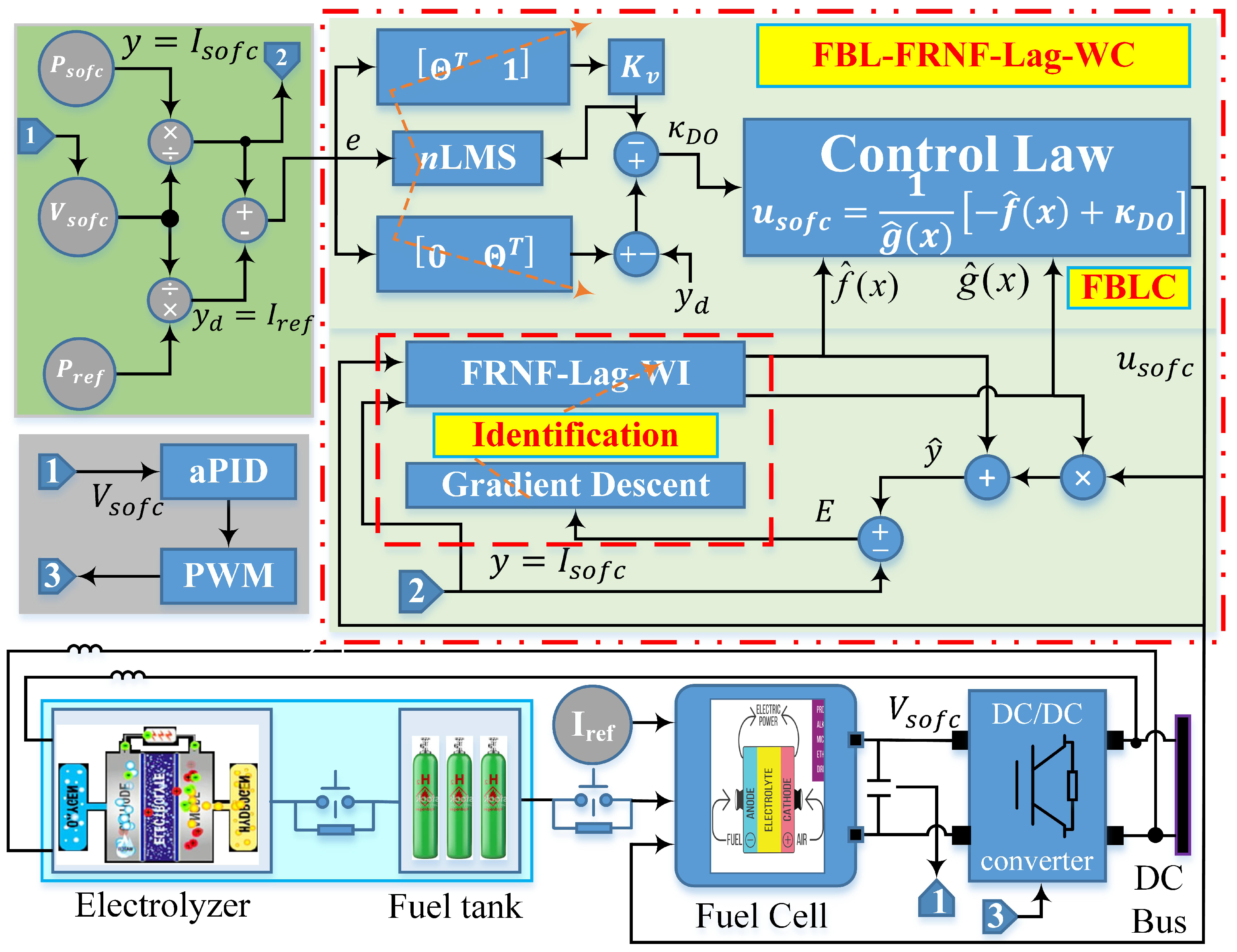
Figure 2 shows the schematic diagram of the internal closed-loop control scheme for the SOFC suggested in this research work. The actual output voltage, reference power, and actual output power are used to generate the input error signal, which is the input to adaptive FBL control. The control scheme generates the output control signal for the SOFC according to the internal structure of the control scheme, as described in Section 3.1.
The major problem in control is in dealing with the nonlinear behavior of the system to be controlled. The nonlinearities are complex and do not have any specific reasons or mathematical models. The inclusion of nonlinearities in the control law makes it more complex and decreases the reliability of the controller due to the unpredictable behavior of the nonlinear functions of the system. FBL is the key to tackling the nonlinearities of the system.
FBL converts nonlinear functions of the system into linear functions, and thus enables one to apply a linear control law on a nonlinear system [3].

3.1. Mathematical Modeling

Consider a nonlinear system:
y n = f ( x ) + g ( x ) u s o f c ,
where y is the system output, f(x) and g(x) are the unknown nonlinear functions, nZ is the degree of the system, u s o f c is the control input, and x = [ y , y ˙ , , y n 1 ) ] T n is the state-space vector.
If the nonlinear system input is expressed in terms of the new input κ D O , then the control law is:
u s o f c = 1 g ( x ) f ( x ) + κ D O .
The control law defined in (9) will linearize the nonlinear system by canceling the nonlinear terms, and it results in the following input–output relation:
y n = κ D O .
Here, the nonlinear functions are estimated online through FRNF-Lag-WI. The objective of the control is now to search for an u s o f c that pulls y ( t ) to the desired trajectory y d ( t ) . The error matrix e is:
e = y ( t ) y d ( t ) .
The tracking error κ is given as [3]:
κ T = Θ T 1 e ,
where Θ = 1 2 n 1 is the weight vector of FBL whose approximate choice ensures that poles of s n 1 + n 1 s n 2 + + 1 in the left half of the complex plane. Θ is updated at every step using the nLMS self-tuning algorithm. The derivative of (12) is:
κ ˙ T = Θ T 1 e ˙ = Θ T 1 y ˙ d ( t ) y ˙ ( t ) = y n T + y d n T + 0 Θ T e = y n + κ D T .
Using (8) in (13):
κ ˙ = f ( x ) + g ( x ) u s o f c + κ D .
Using κ = e x p ( Ξ t ) κ ˙ = Ξ κ and constant Ξ > 0 , if κ is considered as the input in (12) and e is considered as the output, then e 0 as κ 0 . Then, (14) can be rewritten as:
Ξ κ = f ( x ) + g ( x ) u s o f c + κ D .
Now, if f ( x ) and g ( x ) are known, then the FBL technique can be applied to obtain an u s o f c that cancels the nonlinearities of the system and brings κ to zero.
u s o f c = 1 g ( x ) f ( x ) Ξ κ κ D
The estimation of the nonlinear functions, f ^ ( x ) and g ^ ( x ) , is done through FRNF-Lag-WC for the online optimization of design parameters Θ . Then, (16) can be rewritten as:
u s o f c = 1 g ^ ( x ) f ^ ( x ) + κ D O ,
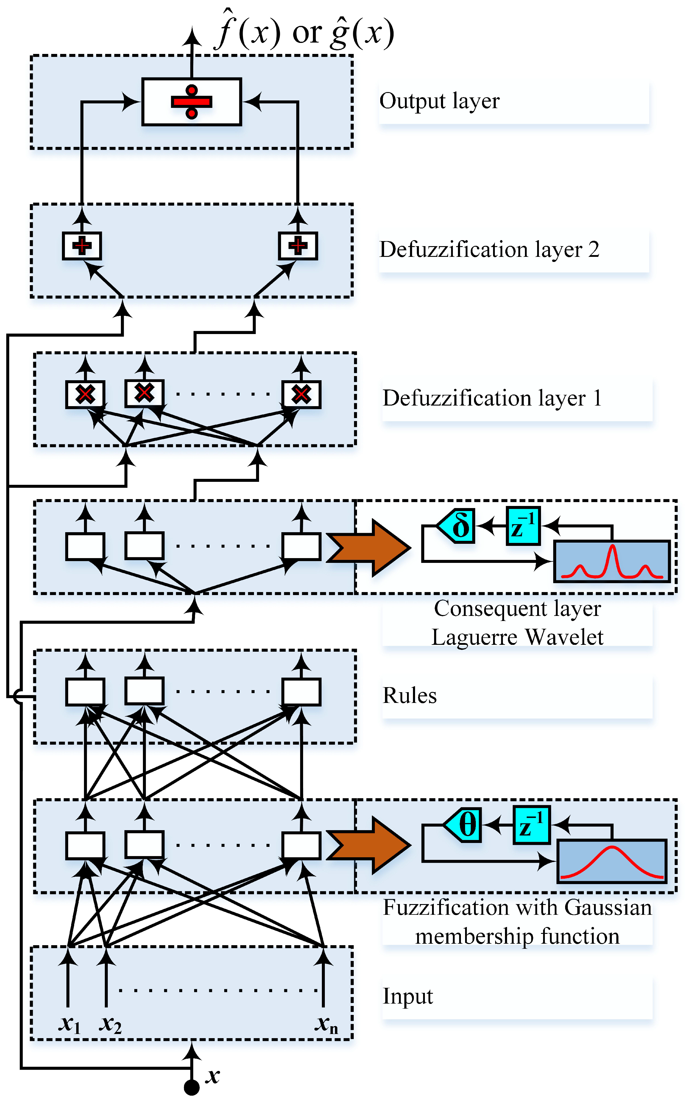
where κ D O = Ξ κ κ D . For the best approximation of f ^ ( x ) and g ^ ( x ) in (17), a multi-layer FRNF-Lag-WC is used in this research work, as shown in Figure 3 [3]. The input to the FRNF-Lag-WC is the difference between the actual and reference current of the SOFC. The outputs of FRNF-Lag-WC are estimated nonlinear functions f ^ ( x ) and g ^ ( x ) . The identified nonlinear system is given as:
y ^ = f ^ ( x ) + g ^ ( x ) u s o f c .
The parameters of the antecedent and consequent parts are updated using a gradient method with the mean square error (MSE) as a cost function, and they are given in Equation (19):
E = 1 2 ( y ^ y ) 2 ,
where E is the identification error, y ^ is given in (18), and y = I s o f c is the actual output of the SOFC.
The gradient descent method is used for fast convergence, and the update equation is given as:
( m + 1 ) = ( m ) Γ ϱ m ,
where is the parameter being updated, ϱ m is the gradient of the cost function at the mth iteration, m is the iteration index, and Γ > 0 is the learning rate.
The antecedent part is based on the Gaussian membership function as follows:
O i ( 2 ) ( k ) = e x p x i k + O i ( 2 ) ( k 1 ) θ i j m i j σ i j 2 ,
where O i ( k ) represents the output of the ith node, the i j subscript shows the jth term of the ith input, superscript (2) indicates the layer number, x i is the input, θ i j is the recurrent weight, and σ i j and m i j are the variance and mean of the ith input and jth membership function.
A Laguerre wavelet is used as a variant of the consequent part in this research work. Laguerre wavelets are defined as:
Ψ p q k ( x ) = 2 k 2 L p p ! 2 k x 2 q + 1 , q 1 2 k 1 x < q 2 k 1 0 , o t h e r w i s e ,
where q = 1 , 2 , P 1 , p = 0 , 1 , 2 p 1 , and k is assumed as a positive integer. L p ( x ) are Laguerre polynomials of degree p with respect to the weight function W ( x ) = 1 on the interval [ 0 , ) and satisfy the following recurrence formula:
L 0 ( x ) = 1 , L 1 ( x ) = 1 x , L p + 2 ( x ) = ( 2 p + 3 x ) L p + 1 ( x ) ( p + 1 ) L p ( x ) p + 2 ,
where p = 0 , 1 , 2 ,
Equation (22) is derived for p = 1 , 2 , q = 0 , 1 , and k = 1 , 2 to obtain the six Laguerre wavelet functions that are used in this research work.
The operation of the suggested multilayer FRNF is as follows.
Layer 1: It receives input and passes it to the next layer. The feedback connections in this layer produce a temporal relationship in the network.
The output is O i ( 1 ) ( k ) = x i .
Layer 2: The membership degree and fuzzy set are estimated in this layer for the Gaussian membership function of all inputs, as given in (21). Layer 3: The product of the membership function is calculated in the rule layer. The number of nodes is determined by the number of rules in this layer.
The output is:
O i ( 3 ) ( k ) = i = 1 n O i ( 2 ) ( k ) = i = 1 n e x p x i + O i ( 2 ) ( k 1 ) θ i j m i j σ i j 2 .
Layer 4: This layer represents the ”THEN” part of the fuzzy rules and calculates the weighted firing strength. The error signal and its own weighted feedback signal are inputs for this layer.
The output is:
O i ( 4 ) ( k ) = H i ( k ) + δ i H i ( k 1 ) ,
where H i = Σ N p = 1 Σ 2 p 1 q = 0 Σ K k = 0 w n m k Ψ p q k , w n m represents the Laguerre wavelet coefficients, and δ i is the feedback weight. The feedback weight is a closed-loop fixed gain for this layer.
Layer 5: The sum of the products of the antecedent and consequent parts of (23) and (24) is computed in the first defuzzification layer.
The output is:
O i ( 5 ) ( k ) = Σ n i = 1 O i ( 4 ) ( k ) O i ( 3 ) ( k ) .
Layer 6: The sum of all of the rules from (23) is computed in the second defuzzification layer.
The output is:
O i ( 6 ) ( k ) = Σ n i = 1 O i ( 3 ) ( k ) .
Layer 7: The nonlinear functions are estimated in the output layer.
The output is:
O f ( 7 ) ( k ) = f ^ ( x ) = O f i ( 5 ) ( k ) O f i ( 6 ) ( k )
O g ( 7 ) ( k ) = g ^ ( x ) = O g i ( 5 ) ( k ) O g i ( 6 ) ( k ) .

3.2. Update Equations for the Parameters of the Antecedent Part

The update equation for variants of the Gaussian membership function is derived from the following chain rule.
E χ i = E y i y i O i ( 2 ) ( k ) O i ( 2 ) ( k ) χ i ,
where χ shows the variants, such as the mean, variance, and feedback weight of the Gaussian membership function.
The update equation for the mean, m i , is:
m i ( k + 1 ) = m i ( k ) + Γ ( y ^ y i ) ( O i ( 4 ) ( k ) O i + 1 ( 4 ) ( k ) ) O i ( 2 ) ( k ) O i + 1 ( 2 ) ( k ) ( O i ( 2 ) ( k ) + O i + 1 ( 2 ) ( k ) ) 2 x i ( 1 ) ( k ) + O i ( 2 ) ( k 1 ) θ i 2 m i 2 ( σ i 2 ) 2 .
The update equation for the variance, σ i , is:
σ i ( k + 1 ) = σ i ( k ) + Γ ( y ^ y i ) ( O i ( 4 ) ( k ) O i + 1 ( 4 ) ( k ) ) O i ( 2 ) ( k ) O i + 1 ( 2 ) ( k ) ( O i ( 2 ) ( k ) + O i + 1 ( 2 ) ( k ) ) 2 ( x i ( 1 ) ( k ) + O i ( 2 ) ( k 1 ) θ i 2 m i 2 ) 2 ( σ i 2 ) 3 .
The update equation for the recurrent weight, θ i , is:
θ i ( k + 1 ) = θ i ( k ) Γ ( y ^ y i ) ( O i ( 4 ) ( k ) O i + 1 ( 4 ) ( k ) ) O i ( 2 ) ( k ) O i + 1 ( 2 ) ( k ) ( O i ( 2 ) ( k ) + O i + 1 ( 2 ) ( k ) ) 2 x i ( 1 ) ( k ) + O i ( 2 ) ( k 1 ) θ i 2 m i 2 ( σ i 2 ) 2 .

3.3. Update Equations for the Consequent Part

The chain rule for updating variants of the consequent part is:
E w i = E y i y i O i ( 4 ) ( k ) O i ( 4 ) ( k ) w i ,
where w i represents the weight of the consequent layer described in layer 4.
The update equation for the weight, w i ( k ) , of the FRNF is:
w i ( k + 1 ) = w i ( k ) γ ( y ^ y i ) ( H 1 + H 2 ) O i ( 2 ) O i ( 2 ) + O i + 1 ( 2 ) ,
where H i represents Laguerre wavelet given in (24).
The following steps summarize the realization of the algorithm for the current control and, hence, power of the SOFC.
  • The measurement system transmits the actual V s o f c and P s o f c and calculates I s o f c , which is the plant output, y.
  • FRNF-Lag-WI captures the nonlinear dynamics, f ^ ( x ) , and g ^ ( x ) of the SOFC system based on the measured signals of the power system. The parameters of FRNF-Lag-WI are instantaneously optimized through the gradient descent algorithm to minimize the identification error defined in (19), which is back-propagated to FRNF-Lag-WI to optimize the membership functions of the antecedent part and weights of the consequent part.
  • In parallel operation, the online estimation produces the appropriate input, κ D O . The coefficient vector, Θ , is optimized through the nLMS algorithm in order to minimize the tracking error of (11).
  • FBL-FRNF-Lag-WC generates an appropriate control law, u s o f c , based on the identified functions, f ^ ( x ) and g ^ ( x ) , as well as the optimized κ D O , as given in (17).
  • The estimated f ^ ( x ) and g ^ ( x ) cancel the nonlinearities of the system model and generate u s o f c .
  • u s o f c in the SOFC controls the molar flow of hydrogen, and hence forces the I s o f c to track I r e f .

4. Results and Discussion

The MATLAB/Simulink R2015a software was used for the preparation of the simulation testbed. The wind speed (m/s), ambient temperature ( C), and solar irradiation (W/m 2 ) were obtained for Islamabad station from the Pakistan Meteorological Department (PMD) for a complete day. The details of the testbed parameters are provided in Section 2, as well as in [3]. The performance of the proposed adaptive FBL-FRNF-Lag-WC is verified against the conventional PID and aPID control schemes, and the results are shown for various parameters. The results were obtained for a simulation time of 24 s, where each second represented one hour.
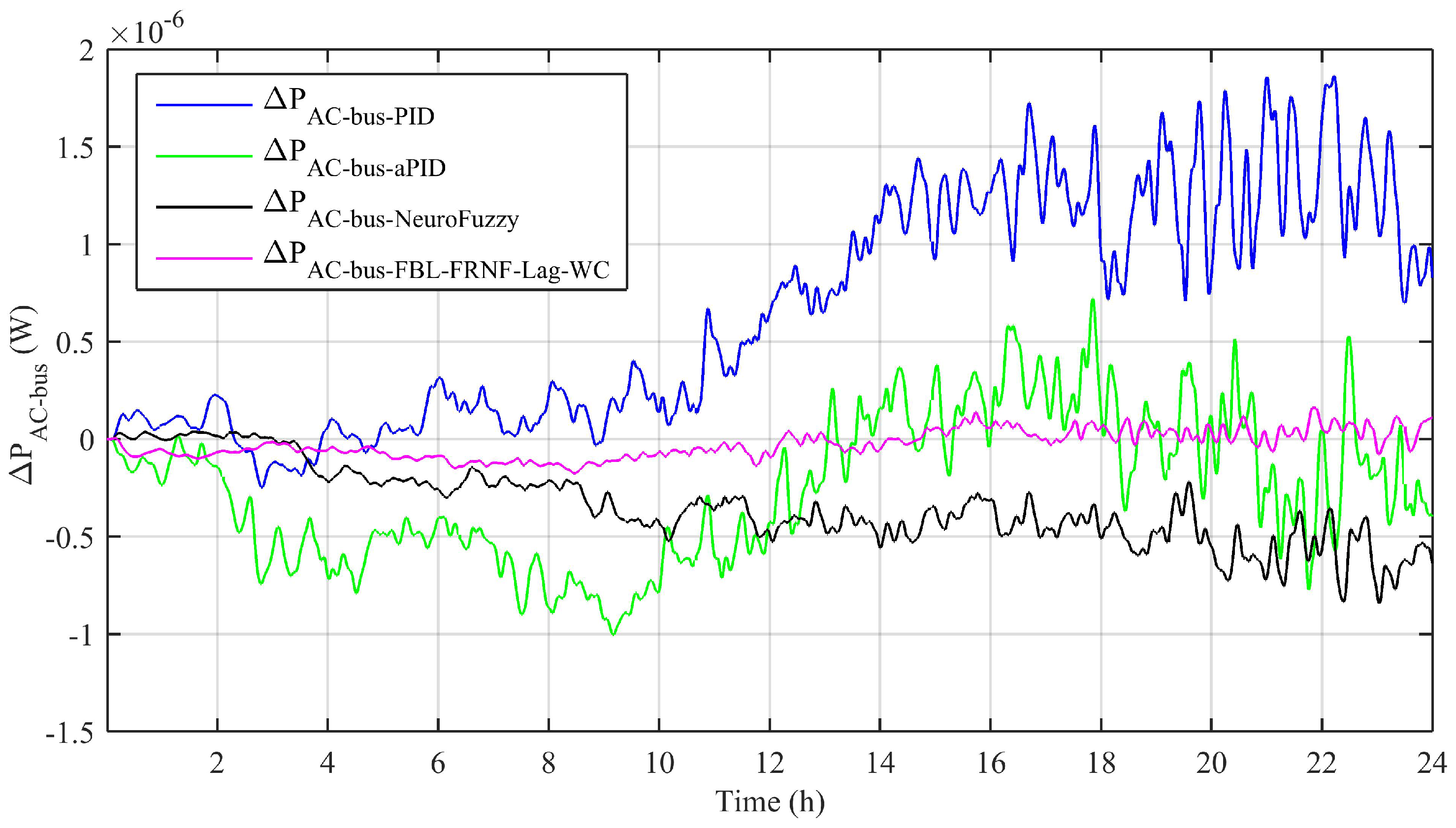
To ensure the stability of the power system, the net power on the AC bus, as well as on the DC bus, must remain zero. Figure 4 shows the net real power on the AC bus. The results clearly show that there was a negligible oscillation in the net AC bus power due to the adaptive FBL-FRNF-Lag-WC. This variation was due to the highly nonlinear load connected to the AC bus. The variations in the net AC bus power produced by the adaptive NeuroFuzzy and by the conventional control schemes were of higher magnitude than that of the adaptive FBL-FRNF-Lag-WC.
Figure 5 shows the net reactive power on the AC bus. Like the net real power, it must also be zero to ensure the stability of the AC bus. It is obvious that the net reactive power for the adaptive FBL-FRNF-Lag-WC is negligible. However, the variation is caused by the use of several converters attached to the AC bus, along with a varying load consisting of a large number of machines. The net reactive power due to the adaptive NeuroFuzzy, PID, and aPID control schemes shows a higher magnitude for the same system compared to the adaptive FBL-FRNF-Lag-WC.
Figure 6 shows the net power on the DC bus. The net power on the DC bus had small variations for the adaptive FBL-FRNF-Lag-WC due to the multiple renewable energy resources and the action of many converters on the bus. The variation was also caused by the variable output of the maximum of the RESs attached to the DC bus. However, the magnitudes of variation due to the adaptive NeuroFuzzy, conventional PID, and aPID control schemes were of much higher magnitudes compared to that of the adaptive FBL-FRNF-Lag-WC.
The SOFC continuously provides power to the DC bus via a converter. Figure 7 shows the electrical output power obtained through the conversion of electrochemical energy within the SOFC. The complete one-day output power profile was based on various load changes and the peak demand. The output power followed the reference signal for the adaptive FBL-FRNF-Lag-WC and gave a higher magnitude of produced power. The output power tracked by the adaptive NeuroFuzzy and the conventional controllers gave low magnitudes, and at certain intervals of time, the conventional control schemes failed to track the desired power flow.
Power quality is one of the most important factors of a power system; it directly affects the overall performance of the system. The total harmonic distortion (THD) produced due to the source converters and load must be zero. However, their presence cannot simply be neglected due to various factors related to power generation from renewable resources, the use of the converters, and the transformers in the whole power system. The content of the THD can be reduced in a power system according to IEEE standards [20]. Figure 8 shows the THD content of the load current produced during the simulation of the various control schemes. The THD produced by the adaptive FBL-FRNF-Lag-WC had the lowest magnitude compared to the other control schemes, which guaranteed the power quality applied to the microgrid.
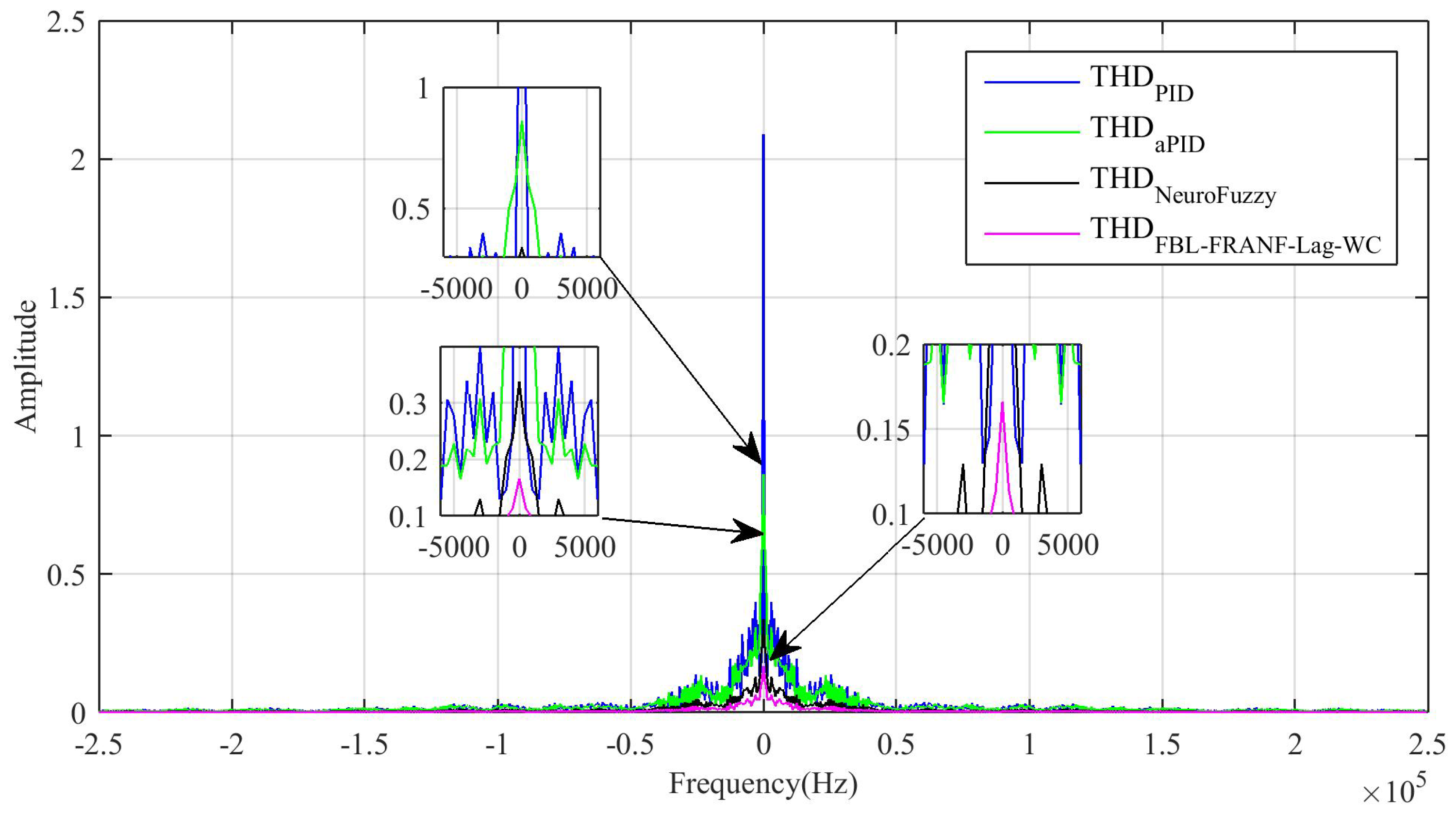
The frequency spectrum of the load current is shown in Figure 9. The magnitude of the frequency spectrum of the load current produced by the proposed control scheme was of a much smaller magnitude compared to the other control schemes. This gave a clear view of the performance of all of the control schemes in terms of the THD produced and the implementation of the power quality factor.
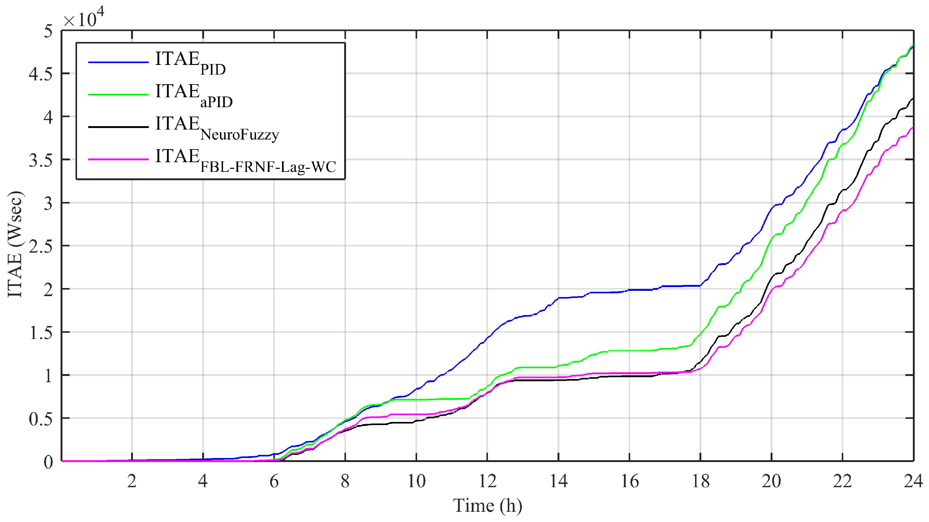
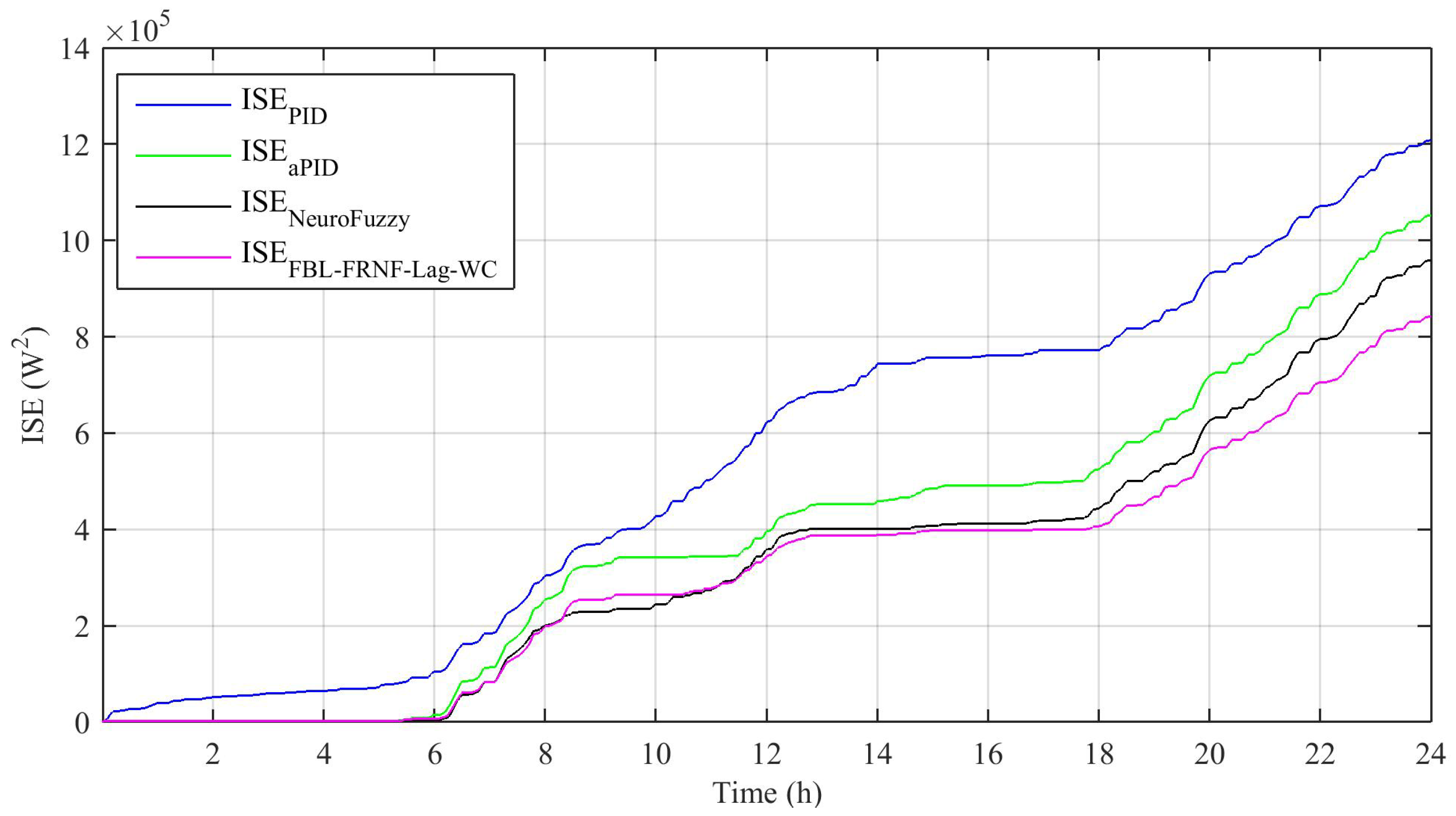
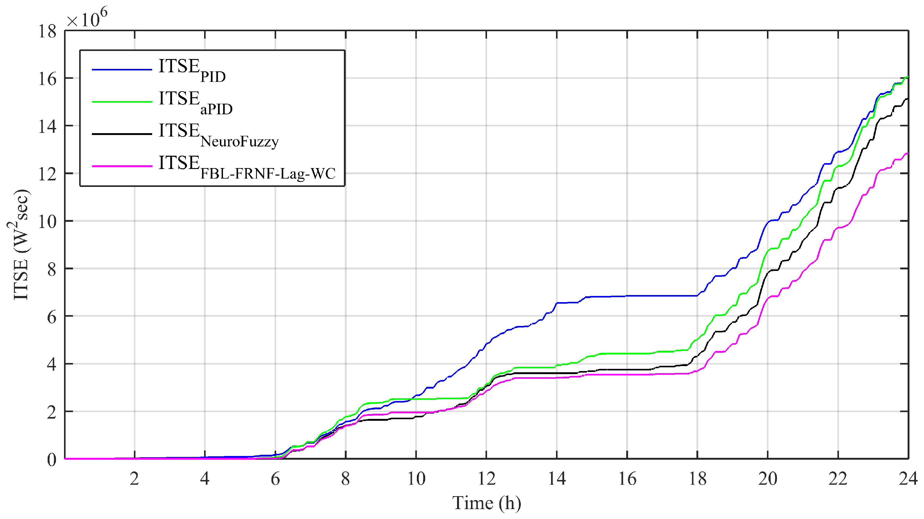
Performance indices, such as the integral absolute error (IAE), integral time-weighted absolute error (ITAE), integral squared error (ISE), and integral time-weighted squared error (ITSE), are shown in Figure 10, Figure 11, Figure 12 and Figure 13, respectively; they were calculated based on the difference between the reference and tracked power, as obtained from Figure 7. The detailed mathematical equations of these indices are given in [21]. The results show that the performance of the adaptive FBL-FRNF-Lag-WC is superior to those of the adaptive NeuroFuzzy, PID, and aPID control schemes.
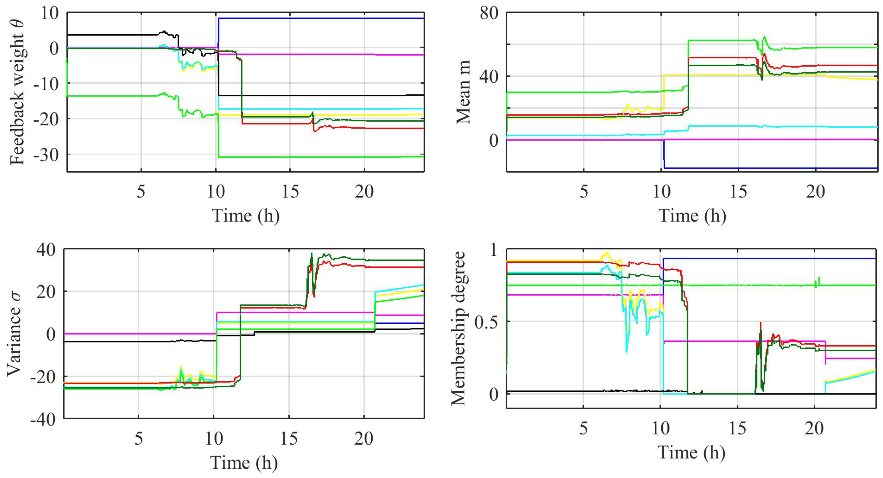
Figure 14a shows the updating of the feedback weight of the Gaussian membership function θ according to (32), Figure 14b shows the updating of the mean of the Gaussian membership function m according to (30), Figure 14c shows the updating of the variance of the Gaussian membership function σ according to (31), and Figure 14b shows the Gaussian membership degree according to (21) for both f ^ ( x ) and g ^ ( x ) , respectively.
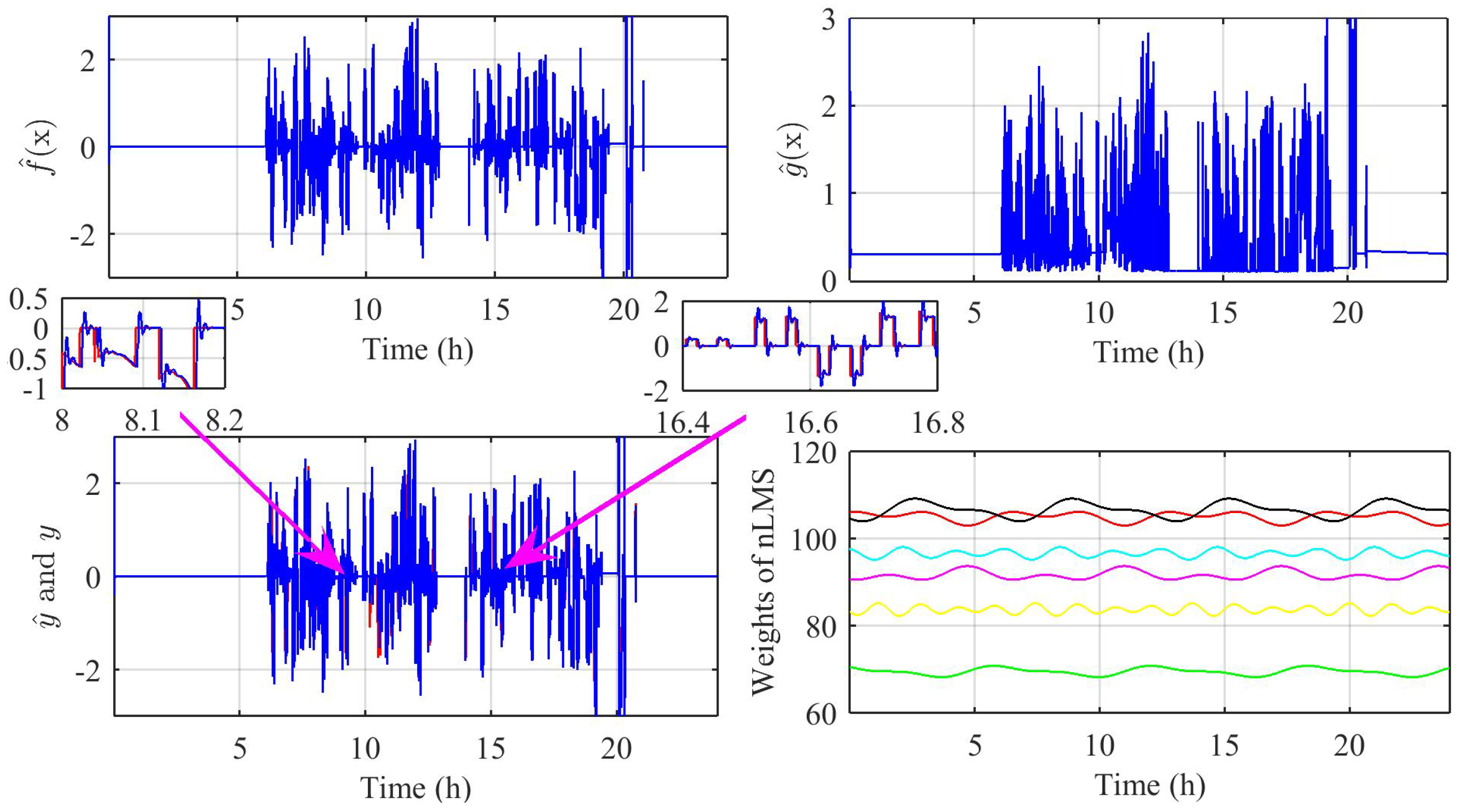
Figure 15a shows the estimated function f ^ ( x ) , and Figure 15b shows the estimated function g ^ ( x ) . It must be noted here that g ^ ( x ) should never be equal to zero at any time instant because of its presence in the denominator of (17). Therefore, a switch is used in the simulation that gives a value greater than 0 whenever a zero comes into g ^ ( x ) . Figure 15c shows the original signal obtained from the SOFC and the identification of it using the FRNF-Lag-WC. This reveals that the identification of an SOFC system is successfully done by the FRNF-Lag-WC, thus proving the adequacy of the proposed control scheme in real-time applications. Figure 15d shows the updating of the weights of nLMS, which depicts the adaptive behavior of the FBL control scheme.

5. Conclusions

This paper presents an adaptive FBL-FRNF-Lag-WC for the operation of an SOFC to ensure its swift response and accurate load following in a grid-connected microgrid. Multiple renewable and nonrenewable resources were considered for this study. The effectiveness of the proposed adaptive FBL-FRNF-Lag-WC was analyzed in comparison with the adaptive NeuroFuzzy, PID, and aPID control schemes for various power qualities and power system stability issues. The application of the proposed control scheme resulted in the least relative change in the active and reactive power, along with a significant reduction of the THD and negligible oscillations in the AC and DC bus power profiles. The overshoot and undershoot in the power tracking profile, DC bus Δ P profile, and AC bus Δ P and Δ Q profiles were negligible for the proposed control scheme compared with the adaptive NeuroFuzzy, conventional PID, and aPID control schemes. The performance was also verified through analysis of the output electric power obtained from the SOFC and performance indices. The overall analysis proved that the suggested adaptive FBL-FRNF-Lag-WC scheme had a superior performance to that of other control schemes and ensured the power system’s stability and reliability.

Author Contributions

M.A. and L.K. designed the idea. M.A. and S.A. worked on the mathematical analysis of the control scheme. M.A. did background research and implemented the model in the software. M.A. conducted the simulations. M.A., S.A., and M.J. compiled and analyzed the results under the supervision of L.K., M.A. formulated the draft. L.K., S.A., and M.J. tailored the article. All authors have read and agreed to the published version of the manuscript.

Funding

This research received no external funding.

Institutional Review Board Statement

Not applicable.

Informed Consent Statement

Not applicable.

Data Availability Statement

Not applicable.

Conflicts of Interest

The authors declare no conflict of interest.

Abbreviations

The following abbreviations are used in this manuscript:
FBL-FRNF-Lag-WCAdaptive feedback-linearization-embedded fully recurrent NeuroFuzzy
Laguerre Wavelet Control
SOFCSolid-oxide fuel cell
FCFuel cell
RESRenewable energy source
ANNArtificial neural network
FBLFeedback linearization
MSEMean square error
PMDPakistan Meteorological Department
THDTotal harmonic distortion
IAEIntegral absolute error
ITAEIntegral time-weighted absolute error
ISEIntegral square error
ITSEIntegral time-weighted square error

References

  1. Nam, H.; Kasada, R.; Konishi, S. Correction to: Economic Analysis Between Diesel and SOFC Electricity via Fusion-Biomass Hybrid Model. J. Fusion Energy 2020, 39, 297–298. [Google Scholar] [CrossRef]
  2. Al-Khori, K.; Bicer, Y.; KoAS, M. Integration of Solid Oxide Fuel Cells into oil and gas operations: Needs, opportunities, and challenges. J. Clean. Prod. 2020, 245, 118924. [Google Scholar] [CrossRef]
  3. Awais, M.; Khan, L.; Ahmad, S.; Mumtaz, S.; Badar, R. Nonlinear adaptive NeuroFuzzy feedback linearization based MPPT control schemes for photovoltaic system in microgrid. PLoS ONE 2020, 15, e0234992. [Google Scholar] [CrossRef] [PubMed]
  4. Mumtaz, S.; Khan, L.; Ahmed, S.; Bader, R. Indirect adaptive soft computing based wavelet-embedded control paradigms for WT/PV/SOFC in a grid/charging station connected hybrid power system. PLoS ONE 2017, 12, e0183750. [Google Scholar] [CrossRef] [PubMed] [Green Version]
  5. Sukumar, S.; Marsadek, M.; Ramasamy, A.; Mokhlis, H.; Mekhilef, S. A Fuzzy-Based PI Controller for Power Management of a Grid-Connected PV-SOFC Hybrid System. Energies 2017, 10, 1720. [Google Scholar] [CrossRef] [Green Version]
  6. Yu, S.; Fernando, T.; Iu, H.H.C. Dynamic Behavior Study and State Estimator Design for Solid Oxide Fuel Cells in Hybrid Power Systems. IEEE Trans. Power Syst. 2016, 31, 5190–5199. [Google Scholar] [CrossRef]
  7. Stambouli, A.; Traversa, E. Solid oxide fuel cells (SOFCs): A review of an environmentally clean and efficient source of energy. Renew. Sustain. Energy Rev. 2002, 6, 433–455. [Google Scholar] [CrossRef]
  8. Singhal, S. Advances in solid oxide fuel cell technology. Solid State Ion. 2000, 135, 305–313. [Google Scholar] [CrossRef]
  9. Basu, S.N.; Pandey, A. Solid Oxide Fuel Cells: Recent Scientific and Technological Advancements. JOM 2019, 71, 3780–3781. [Google Scholar] [CrossRef] [Green Version]
  10. Zakaria, Z.; Awang Mat, Z.; Abu Hassan, S.H.; Boon Kar, Y. A review of solid oxide fuel cell component fabrication methods toward lowering temperature. Int. J. Energy Res. 2020, 44, 594–611. [Google Scholar] [CrossRef]
  11. Jienkulsawad, P.; Skogestad, S.; Arpornwichanop, A. Control structure design of a solid oxide fuel cell and molten carbonate fuel cell integrated system: Bottom-up analysis. Energy Convers. Manag. 2020, 220, 113021. [Google Scholar] [CrossRef]
  12. Baldi, F.; Wang, L.; Pérez-Fortes, M.; Maréchal, F. A Cogeneration System Based on Solid Oxide and Proton Exchange Membrane Fuel Cells With Hybrid Storage for Off-Grid Applications. Front. Energy Res. 2019, 6, 139. [Google Scholar] [CrossRef]
  13. Mumtaz, S.; Khan, L. Adaptive control paradigm for photovoltaic and solid oxide fuel cell in a grid-integrated hybrid renewable energy system. PLoS ONE 2017, 12, e0173966. [Google Scholar] [CrossRef]
  14. Carré, M.; Brandenburger, R.; Friede, W.; Lapicque, F.; Limbeck, U.; da Silva, P. Feed-forward control of a solid oxide fuel cell system with anode offgas recycle. J. Power Sources 2015, 282, 498–510. [Google Scholar] [CrossRef]
  15. Li, Y.; Wu, Q.; Zhu, H. Hierarchical Load Tracking Control of a Grid-Connected Solid Oxide Fuel Cell for Maximum Electrical Efficiency Operation. Energies 2015, 8, 1896–1916. [Google Scholar] [CrossRef]
  16. Devi, P.S.; Sharma, A.D.; Maiti, H.S. Solid Oxide Fuel Cell Materials: A Review. Trans. Indian Ceram. Soc. 2004, 63, 75–98. [Google Scholar] [CrossRef]
  17. Liu, Y.H.; Brandon, N.P.; Liu, M. Electrical Models of SOFC for Power Generation. In Proceedings of the 2012 Asia-Pacific Power and Energy Engineering Conference, Shanghai, China, 27–29 March 2012; pp. 1–4. [Google Scholar] [CrossRef]
  18. Awais, M. ES-5700 Energy Server; Bloom Energy Corporation: Sunnyvale, CA, USA, 2012. [Google Scholar]
  19. Dwivedi, S. Solid oxide fuel cell: Materials for anode, cathode and electrolyte. Int. J. Hydrogen Energy 2020, 45, 23988–24013. [Google Scholar] [CrossRef]
  20. IEEE Standard for Interconnection and Interoperability of Distributed Energy Resources with Associated Electric Power Systems Interfaces; IEEE Std 1547-2018 (Revision of IEEE Std 1547-2003); IEEE: New York, NY, USA, 2018; pp. 1–138. [CrossRef]
  21. Zafran, M.; Khan, L.; Khan, Q.; Ullah, S.; Sami, I.; Ro, J.S. Finite-Time Fast Dynamic Terminal Sliding Mode Maximum Power Point Tracking Control Paradigm for Permanent Magnet Synchronous Generator-Based Wind Energy Conversion System. Appl. Sci. 2020, 10, 6361. [Google Scholar] [CrossRef]
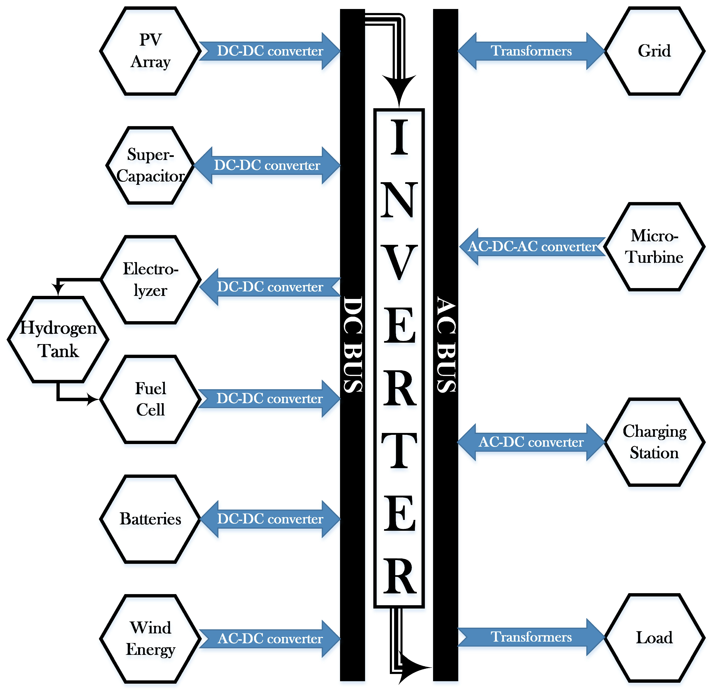
Figure 1. Schematic diagram of the proposed microgrid.
Energies 14 01850 g001
Figure 2. Closed-loop control of the solid-oxide fuel cell (SOFC).
Energies 14 01850 g002
Figure 3. Architecture of the Fully Recurrent NeuroFuzzy System.
Energies 14 01850 g003
Figure 4. Net real power on the AC bus, Δ P A C .
Energies 14 01850 g004
Figure 5. Net reactive power on the AC bus, Δ Q A C .
Energies 14 01850 g005
Figure 6. Net power on the DC bus, Δ P D C .
Energies 14 01850 g006
Figure 7. Output power of the SOFC.
Energies 14 01850 g007
Figure 8. % Δ THD in the load current.
Energies 14 01850 g008
Figure 9. Frequency spectrum of the load current.
Energies 14 01850 g009
Figure 10. Integral absolute error (IAE) evolution.
Energies 14 01850 g010
Figure 11. Integral time-weighted absolute error (ITAE) evolution.
Energies 14 01850 g011
Figure 12. Integral squared error (ISE) evolution.
Energies 14 01850 g012
Figure 13. Integral time-weighted squared error (ITSE) evolution.
Energies 14 01850 g013
Figure 14. (a) Feedback weight θ , (b) mean m (c) variance σ , and (d) membership degree.
Energies 14 01850 g014
Figure 15. (a) Estimated function f ^ ( x ) ; (b) estimated function g ^ ( x ) ; (c) identification of the SOFC with fully recurrent NeuroFuzzy Laguerre wavelet control (FRNF-Lag-WC); (d) weights of nLMS.
Energies 14 01850 g015
Publisher’s Note: MDPI stays neutral with regard to jurisdictional claims in published maps and institutional affiliations.