Article

Research on Differential Protection of Generator Based on New Braking Mode

1
School of Electronics and Information, Xi’an Polytechnic University, Xi’an 710048, China
2
School of Electrical and Control Engineering, Xi’an University of Science and Technology, Xi’an 710054, China
3
School of Electrical Engineering, Xi’an Jiaotong University, Xi’an 710049, China
*
Author to whom correspondence should be addressed.
Energies 2021, 14(7), 1857; https://doi.org/10.3390/en14071857
Submission received: 5 March 2021 / Revised: 21 March 2021 / Accepted: 24 March 2021 / Published: 26 March 2021
(This article belongs to the Section F: Electrical Engineering)

Abstract

:
In view of the difficulties in coordination between reliability and sensitivity of conventional generator differential protection, this paper presents a novel generator differential protection scheme based on a new braking method. On the basis of the mathematical model of the field-circuit coupling method and the electrical network cascade characteristics, the stator windings were combined and decoupled by the improved six-sequence component method to eliminate electromagnetic coupling between winding coils. In accordance with the basic characteristics of longitudinal impedance, the function of sub-item discrimination was realized. Numerous simulations and the up-to-date dynamic experiments showed that the proposed method has good state discrimination ability and can effectively resist the influence of current transformer saturation. Thus, it has an excellent prospect for engineering promotion.

1. Introduction

Over the past few years, we have witnessed that large generators play an important role in the optimization and upgrading of power supply and grid structure. On one hand, new energy power generation has been developed on a large scale in China. The proportion of new energy power generation installed capacity exceeded 50% for the first time in 2017, and the intermittent and randomness of its output brings challenges to the stability of the power system [1,2]. On the other hand, the wide application of new power electronic technologies, such as large-scale DC transmission and flexible AC/DC transmission, makes the operating characteristics of the power system more complex and changeable [3,4]. As the main power source of the power system, large generators can not only cope with the complex operating environment of the power grid, but also provide stronger support for the power grid.
In the case of the characteristics of high operating efficiency and low pollution, large generators’ installed capacity has increased steadily. Its design, structure, technology, operation, etc. have become more complicated, and higher requirements have been put forward for its protection configuration [5]. In fact, traditional differential protection has the defect that it is hard to coordinate between anti-misoperation and non-rejection. Thus, an in-depth investigation of the change rule of each electrical quantity after an internal fault, which occurs in the generator, is conducive to the research of new generator protection algorithms and further improves the effectiveness of generator operation.
In the system, the stator internal short circuit is a kind of common fault that may compromise the security of the generator. Relevant scholars have done a lot of research on the protection types of it [6,7,8]. In general, generator differential protection is the main protection for large-scale power station generators and generator transformers. Pillai P. et al. [9] analyzes and discusses the choice of neutral grounding method and makes a detailed comparison of the influence of high-resistance grounding method and arc suppression coil grounding method in differential protection. Chen, X. et al. [10] shows that, although large units used separated-phase enclosed bus generally, it is still necessary to consider the possibility of phase-to-phase short-circuit faults in the generator voltage circuit. So. the protection areas of generator differential protection and transformer differential protection should overlap each other. Shipp D. et al. [11] shows that if the stator winding of the synchronous generator is short-circuited between the upper and lower bars of the same slot and the end of the coil, it will cause great harm to the motor. When an internal fault occurs, the short-circuit current increases sharply, which not only produces destructive electromagnetic forces but also overheats and burns the windings and iron cores. Therefore, the protection must act immediately to prevent serious damage to the generator. Safari-Shad N. et al. [12,13] adopts full longitudinal differential protection and incomplete longitudinal differential protection, which can remove faulty components from the power system selectively. However, it can be seen that the fault analysis mainly stays on the short-circuit level of the terminal of the protected equipment. The corresponding main equipment protection sensitivity analyses’ calculation is also limited to the verification of the short circuit of the terminal. So, even if the sensitivity coefficient verification is qualified, when the internal failure of the protected equipment occurs, it is difficult to ensure that the protection device is sensitive and quick to operate. Therefore, from the perspective of unit protection, it is necessary to analyze the distribution qualitatively and quantitatively and change laws of various electrical quantities during internal faults to design the configuration scheme of internal fault protection, so as to achieve the purpose of reducing fault damage. Zhu, Y. et al. [14] shows that rotor second harmonic current protection can reflect the abnormal operating conditions of electrical components but has higher requirements for the reliability and performance of the signal source. Jaafari K. et al. [15] makes the use of the scalar product braking longitudinal differential protection, which has defects in setting calculation and principles’ design. Gao, B. et al. [16] uses transverse differential protection, which has a simple principle and high sensitivity, but it has no protective effect on the short circuit of the external lead of the machine end and the on-site debugging is more complicated. Zheng, T. et al. [17] utilizes fundamental longitudinal zero-sequence voltage protection, but its protection action has a low correct rate and there are some areas that cannot be protected. Xia, J. et al. [18,19] proposes to solve the problems caused by the saturation of conventional current transformers and to ensure the accuracy of the collected current sampling values or phasors in order to avoid protection malfunctions. Therefore, researching a new braking method for generator differential protection is beneficial to the safe operation of the power system.
Firstly, in view of the problems of traditional differential protection in generator protection, this research made use of the field-circuit combination method [20] and took the influence of the mutual inductance of the generator’s internal windings into consideration to build a more complete, large-scale, turbo-generator model and to reduce complexity and improve accuracy.
Secondly, on the basis of the calculation method for the longitudinal impedance of transmission line at both ends [21], an improved algorithm suitable for generator differential protection was proposed. This algorithm retained the operating characteristics of the current longitudinal differential protection, combined the characteristics of the generator stator windings, and utilized the differential current of the fault component to enhance the robustness of the algorithm. The ratio of the voltage fault component difference at both ends to the positive sequence series impedance of the winding was used as the braking amount of protection and the reliability of the improved algorithm was further improved. By improving the decoupling of the six-sequence component method, the improved algorithm was constructed in this paper to reduce the influence of the stator winding phase coupling on the protection and realize its sub-state recognition function.

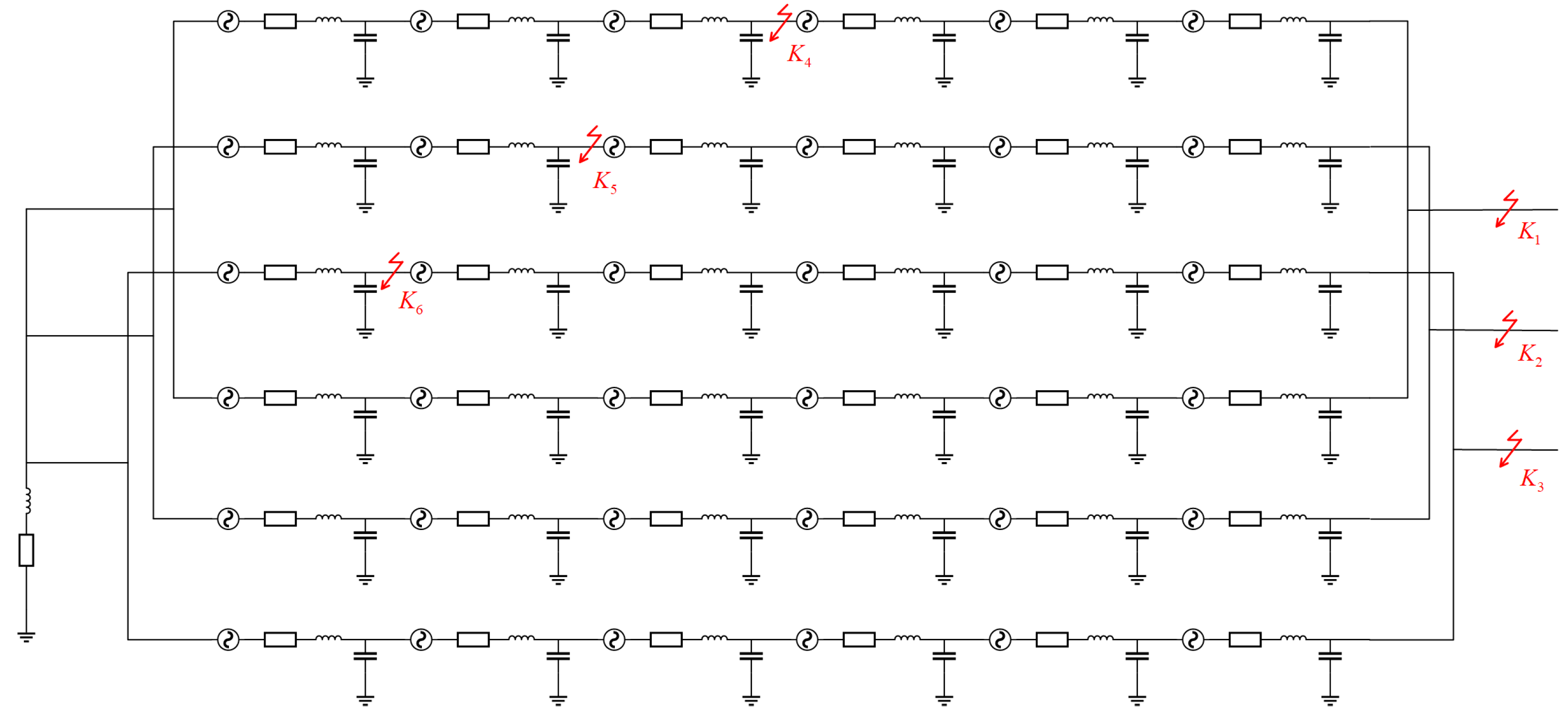
2. Improved Decoupling Method of Generator Stator Winding

The classical generator short-circuit fault calculation methods are mainly the symmetrical component methods [22,23]. However, when the internal generator fault happens, the sequence components are interdependent. The DC component, the fundamental frequency component, and double frequency component in the stator and rotor will affect the change characteristics of the electrical quantity. In this case, in the light of the superposition principle, the symmetrical component method is not suitable for the internal fault analysis for large generators. When a short-circuit fault occurs in the winding, the mutual inductance not only exists between phases, but also loops. So, the six-sequence component analysis method can be used for this case [24,25]. For the three-phase, double-layer winding, the conductors of each layer are divided into upper and lower layers. The coil is composed of the upper conductor in one slot and the lower conductor in the other, making the stator winding parameters of the same slot asymmetrical. This causes a deviation between the results obtained by the six-sequence component method and the actual results, and then the sequence component decomposition method must be adjusted.
Referring to the stator windings, this research used the improved six-sequence component method for decoupling [26,27]. Firstly, the current was decomposed into positive sequence, negative sequence, and zero sequence. Then, the zero sequence was decomposed into zero-sequence identical direction vectors and zero-sequence reverse direction vectors, while the positive sequence and negative sequence remained unchanged.
As shown in Figure 1, the parameters of the stator winding loop I and II at the same slots were different, but the internal parameters of each loop were symmetric. Zs1 was the self-inductance of the winding stator winding I loop, and Zm1 was the mutual inductance between phases, Zs2 was the self-inductance of the stator winding of loop II, Zm2 was the mutual inductance between phases, and Zp was the mutual inductance between two stator winding loops in the same slot. The voltage–current relationship between the stator windings can be written in a vector matrix, as in Equation (1).
Δ U ˙ I A Δ U ˙ I B Δ U ˙ I C Δ U ˙ II A Δ U ˙ II B Δ U ˙ II C = Z s 1 Z m 1 Z m 1 Z p Z p Z p Z m 1 Z s 1 Z m 1 Z p Z p Z p Z m 1 Z m 1 Z s 1 Z p Z p Z p Z p Z p Z p Z s 2 Z m 2 Z m 2 Z p Z p Z p Z m 2 Z s 2 Z m 2 Z p Z p Z p Z m 2 Z m 2 Z s 2 I ˙ I A I ˙ I B I ˙ I C I ˙ II A I ˙ II B I ˙ II C
where Δ U ˙ I A , Δ U ˙ II A , Δ U ˙ I B , Δ U ˙ II B , Δ U ˙ I C , Δ U ˙ II C are, respectively, the voltage drops across winding stator winding.
By using the symmetrical component method, Equation (1) can be decomposed into positive sequence, negative sequence, and zero sequence, as in Equation (2).
Δ U ˙ I 0 Δ U ˙ I 1 Δ U ˙ I 2 Δ U ˙ II 0 Δ U ˙ II 1 Δ U ˙ II 2 = Z I 0 3 Z p Z I 1 Z I 2 3 Z p Z II 0 Z II 1 Z II 2 I ˙ I 0 I ˙ I 1 I ˙ I 2 I ˙ II 0 I ˙ II 1 I ˙ II 2
In Equation (2), the subscript I represents loop I, II represents loop II, 0 represents zero sequence, 1 represents positive sequence, and 2 represents negative sequence.
It can be obtained from Equation (2) that there is no coupling between the positive sequence and the negative sequence of the two loops for the winding stator winding after transformation and only the zero sequence of the two loops is coupled. Therefore, it is only necessary to decouple the zero-sequence mutual inductance between the lines. So, it is going to extract the zero-sequence component in Equation (2), as in Equation (3).
Δ U ˙ I 0 Δ U ˙ II 0 = Z I 0 3 Z p 3 Z p Z II 0 I ˙ I 0 I ˙ II 0
Equation (3) is equivalent, as in Equation (4).
D U ˙ 0 = Z 0 I ˙ 0
By decoupling the zero-sequence mutual inductance, diagonalizing Z0, where Z 0 = Z I 0 3 Z p 3 Z p Z II 0 , and recording the diagonalized change matrix as = 1 1 γ 1 γ 2 , including γ 1 = Z II 0 Z I 0 + Z II 0 Z I 0 2 + 36 Z p 2 6 Z p , γ 2 = Z II 0 Z I 0 Z II 0 Z I 0 2 + 36 Z p 2 6 Z n .
Perform ∏ transformation on Equation (4), as in Equation (5),
Δ U ˙ 0 = 1 Z 0 I ˙ 0
to write in matrix form after equivalent, as in Equation (6):
Δ U ˙ 10 Δ U ˙ 20 = Z 10 Z 20 I ˙ 10 I ˙ 20
where Δ U ˙ 10 and I ˙ 10 are the first components of the zero-sequence voltage and current after decoupling; Δ U ˙ 20 and I ˙ 20 are the second components of the zero-sequence voltage and current after decoupling; Z10 is the impedance corresponding to the first component of the zero sequence, i.e., Z 10 = 1 2 Z I 0 + Z II 0 + Z I 0 Z II 0 2 + 36 Z p 2 ; and Z20 is the impedance corresponding to the second component of the zero sequence, i.e., Z 20 = 1 2 Z I 0 + Z II 0 Z I 0 Z II 0 2 + 36 Z p 2 .
Combine Equation (3) and Equation (6), as in Equation (7).
Δ U 10 Δ U 11 Δ U 12 Δ U 20 Δ U 21 Δ U 22 = Z 10 Z 11 Z 12 Z 20 Z 21 Z 22 I 10 I 11 I 12 I 20 I 21 I 22
From Equation (7), the impedance matrix can be obtained as a diagonal matrix, the decoupling between the double-circuit stator winding of the generator stator winding has been completed, and the influence of the phase coupling of the stator winding can be eliminated after decoupling.

3. Improved Algorithm of Generator Differential Protection

Figure 2a,b shows the R-L (Resistive Load) single-phase stator winding equivalent power frequency fault component models when the external and internal faults of the generator stator windings occur, respectively [28]. The theoretical analysis ignores the influence of the ground capacitance.
In Figure 2, Δ U ˙ l , Δ U ˙ r , Δ I ˙ l , and Δ I ˙ r are the voltage fault components and current fault components obtained on the l side and r side, respectively; Zls and Zrs are the equivalent system impedances at the l side and r side; Zm is the excitation impedance; Zl and Zr are the equivalent leakage impedance inside the generator, respectively; I ˙ m is the excitation current; and the reference direction is from the bus bar to the generator.

3.1. Ratio Braking Differential Protection

In view of the differential protection with traditional ratio braking characteristics, we can get:
I ˙ o p = Δ I ˙ l + Δ I ˙ r I ˙ r e s = 1 2 Δ I ˙ l Δ I ˙ r .
Its action criterion is as in Equation (9).
I ˙ o p I ˙ a c t . min             I ˙ r e s I ˙ res . min I ˙ o p 1 2 I ˙ res I ˙ res . min I ˙ act . min             I ˙ res I ˙ res . min
where I ˙ o p is the differential current, I ˙ r e s is the braking current, I ˙ act . min is the minimum operating current, and I ˙ res . min is the minimum braking current.

3.2. Differential Protection Algorithm Based on Longitudinal Impedance

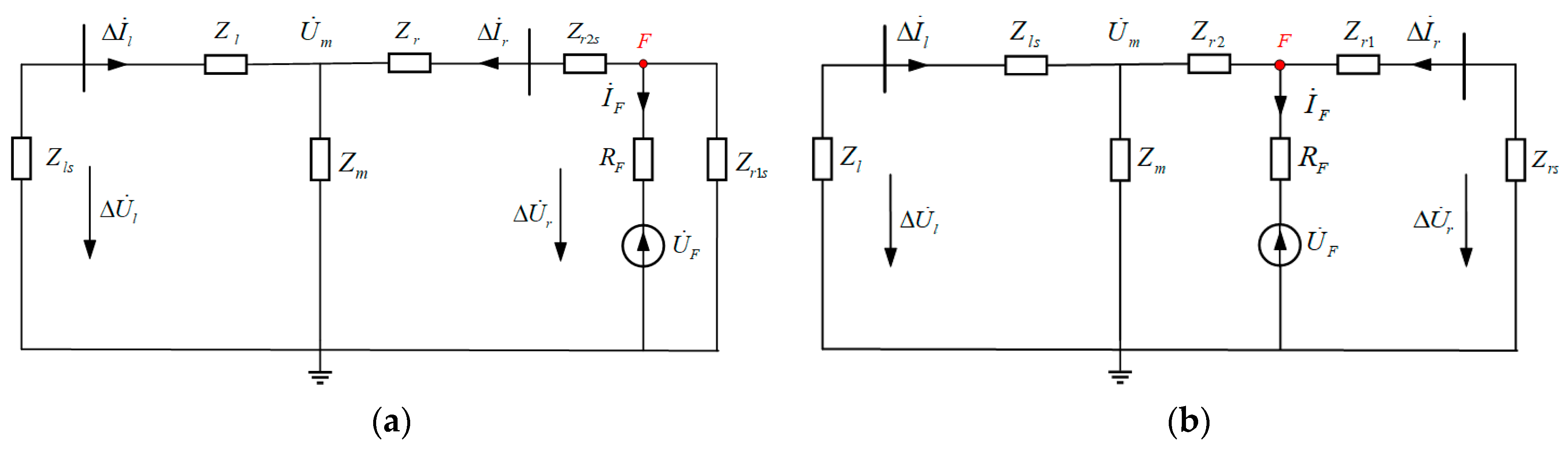
3.2.1. External Fault

As shown in Figure 2a, if an external fault occurs at the side of the generator, U ˙ F is the voltage at the fault point, I ˙ F is the current at the fault point, and Zr1s, Zr2s are the two equivalent impedances separated after an external fault. When the generator is operating normally or an external fault occurs, we can get: Z m Z r + Z r s . If the influence of shunt current caused by Zm is not considered, the deductions can be obtained as in Equations (10) and (11).
Δ U ˙ l = Δ I ˙ l Z l s Δ U ˙ r = U ˙ F Δ I ˙ r Z r 2 s = Δ U ˙ l + Δ I ˙ r Z l + Z r
Δ U ˙ o p = Δ I ˙ l Z l + Z r = Δ I ˙ r Z l + Z r Δ I ˙ o p = Δ I ˙ l Δ I ˙ r = Δ I ˙ l + Δ I ˙ r
Based on the fault network shown in Figure 2, the longitudinal impedance expresses as in Equation (12).
Δ Z o p = Δ U ˙ o p Δ I ˙ o p
From the internal structure of the generator, the positive sequence stator winding impedance of the winding does not need to be adjusted and reset in accordance with the changes of the system operation mode. Therefore, in the ideal state, the amplitude of Δ I ˙ l and Δ I ˙ r is basically the same and there exists Δ I ˙ o p = Δ I ˙ l + Δ I ˙ r = 0 , i.e., Δ I ˙ l > > Δ I ˙ o p . Equation (12) can be transferred to obtain an improved algorithm of the current differential protection form expressed, as in Equation (13).
Δ I ˙ l + Δ I ˙ r < Δ U ˙ l Δ U ˙ r Z o p
According to the above derivation, for external faults, the amount of action is obviously smaller than the braking amount, which ensures the reliability of the improved algorithm.

3.2.2. Internal Fault

As shown in Figure 2b, for internal fault at the r side of the generator, U ˙ F is the voltage at the fault point, I ˙ F is the current at the fault point, and Zr1 and Zr2 are two equivalent leakage impedances separated at the internal fault. When the generator is at normal operation, we can get Z m Z r 1 + Z r 2 + Z r s . If the influence of shunt current caused by Zm is not considered, the deductions can be obtained as in Equations (14) and (15).
Δ U ˙ l = Δ I ˙ l Z l s = U ˙ F Δ I ˙ l Z l + Z r 2 Δ U ˙ r = U ˙ F Δ I ˙ r Z r 1 = Δ I ˙ r Z r s
Δ U ˙ o p = Δ I ˙ l Z l + Z r Δ I ˙ r Z r 1 Δ I ˙ o p = Δ I ˙ l + Δ I ˙ r
In Equation (15), the direction of Δ I ˙ l and Δ I ˙ r is the same as the direction of the reference current, and from Δ I ˙ o p = Δ I ˙ l + Δ I ˙ r , we can get: Δ I ˙ l Δ I ˙ o p and Δ I ˙ r Δ I ˙ o p . Equation (15) can be transformed into an improved algorithm of the current differential protection form expressed, as in Equation (16).
Δ I ˙ l + Δ I ˙ r > Δ U ˙ l Δ U ˙ r Z o p
According to the above derivation, for internal faults of the generator, the action volume is significantly greater than the braking volume, which ensures the sensitivity of the improved algorithm for internal faults.

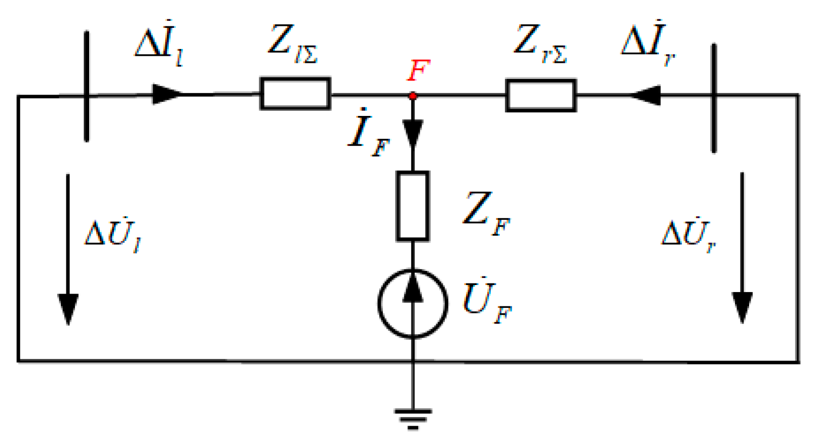
3.2.3. Generator Differential Protection Algorithm Based on Longitudinal Impedance

From the above analyses, the discriminant of the new type of protection can be obtained as in Equation (17).
Δ I ˙ l + Δ I ˙ r Δ U ˙ l Δ U ˙ r Z o p > I s e t
When an external fault occurs on the generator, the amount of action is significantly smaller than the braking amount, the above Equation (17) is not established, and the protection is reliable and does not operate. When an internal fault occurs on the generator, the amount of action is obviously greater than the amount of braking, the above Equation (17) is established, and the protection is sensitive.

3.3. The Effect of Transition Resistance under Transient Conditions

The last section analyzes the differential protection method from the principle of using the steady-state transition resistance. This section considers the influence of the state of capacitance or inductance under transient conditions and makes corresponding analyses. Figure 3 is the simplified equivalent circuit.
As shown in Figure 3, when a phase-to-phase short-circuit internal fault occurs in generator, the current expression at the fault point occurs, as shown in Equation (18).
I ˙ F = U ˙ F Z F + Z l Z r
where ZF is the transient impedance and Z l Z r is the parallel connection of the equivalent impedance on both sides of the fault point.
When the impedance ZF is capacitive, the value of I ˙ F is larger than when it is resistive, and the protection is more sensitive. When the impedance ZF is inductive, the setting value Iset is set according to the maximum unbalanced current to avoid the external fault. If the inductance is large enough to affect the correct action of protection, the filtering effect can be strengthened and the discrimination time can be extended to protect.

4. Performance Analysis

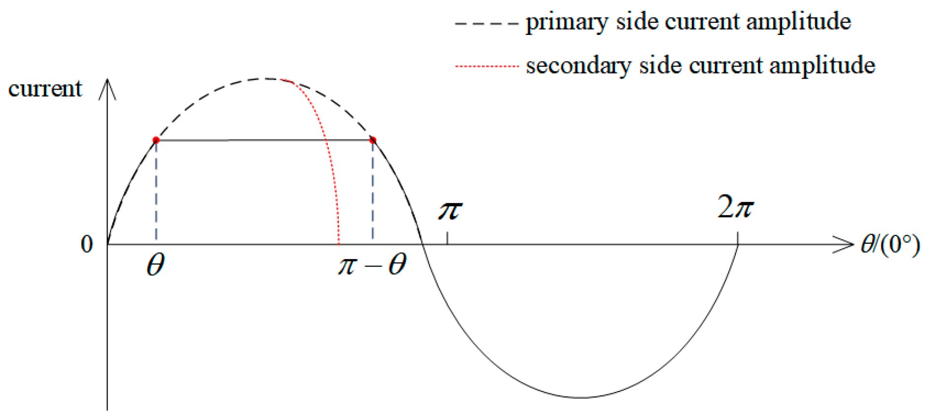
Anti-Current Transformer Saturation Capability

When an external fault occurs in the stator winding of the generator, the short-circuit current near the fault side increases, it causes the current transformer near the fault side to saturate, the unbalanced current increases sharply, and there is a hidden danger of protection malfunction. This section combines the current transformer saturation law and the law of conservation of energy in the process of short-circuit current, taking an example of an external fault close to the fault side of a single-phase winding for analysis. The equivalent current waveform of the current transformer after transient saturation is shown in Figure 4. The figure, respectively, shows the primary-side current amplitude before saturation of the current transformer and the secondary-side current amplitude under the most severe transient saturation of the current transformer. The conduction angle θ is defined as the difference between the current zero-crossing point and the saturation point. The θ ~ πθ is the transient saturation of the current transformer.
The power frequency current component after the transient saturation of the current transformer can be expressed as in Equation (19).
I m 0 = π π sin t · sin t d t = sin θ ( π 2 θ ) 2 cos θ
It can be seen from Figure 4 that in the negative half waveform of the current, the excitation current is gradually demagnetized. At the same time, the excitation inductance gradually increases and the amplitude of the fundamental component of the current transformer current does not attenuate too much. In the positive half waveform of the current, the excitation current enters the saturation process from the operating point. When the transient saturation of the current transformer exceeds the conduction angle θ, the fundamental component of the current transformer current attenuates as the degree of transient saturation increases. When the transient saturation of the current transformer reaches π, the current transformer saturation is the most serious at this time. The qualitative reflection of the current decays to 50% of the original due to saturation. So, the transient current is half of the original current.
Substituting this conclusion into Equation (8) for analysis, the current amplitude is 1 2 Δ I ˙ r and the phase is basically unchanged.
When the transient saturation angle of the current transformer is π, the action amount and braking amount of the traditional algorithm can be expressed as in Equation (20).
I ˙ o p = Δ I ˙ l + Δ I ˙ r = Δ I ˙ l 1 2 Δ I ˙ r I ˙ r e s = 1 2 Δ I ˙ l + 1 2 Δ I ˙ r = 1 2 Δ I ˙ l + 1 4 Δ I ˙ r
When an external fault occurs and the excitation current is ignored, it is Δ ˙ l Δ I ˙ r . So, the discrimination margin of the differential protection is K r e l = I ˙ set I ˙ res . max = 1.5 . When the fault current transformer outside the area is saturated, its reliability coefficient is 1.5.
At the same time, when the transient saturation angle of the current transformer is π, the action amount and braking amount of the improved algorithm can be expressed as in Equation (21).
I ˙ o p = Δ I ˙ l + Δ I ˙ r = Δ I ˙ l 1 2 Δ I ˙ r I ˙ r e s = Δ U ˙ l Δ U ˙ r Z o p = Δ I ˙ l + 1 2 Δ I ˙ r
When an external fault occurs and the excitation current is ignored, it is Δ I ˙ l Δ I ˙ r . The single-sided current transformer is most severely saturated. So K rel = I ˙ set I ˙ res . max = 3 shows that the reliability coefficient of this algorithm has a double margin at least. Therefore, the improved algorithm has a strong ability to resist transient saturation of current transformers in generator windings.

5. Simulation Verification

5.1. Digital Simulation

5.1.1. Simulation System and Its Parameters

Aiming at verifying the performance of the improved algorithm for generator differential protection proposed in this paper, the simulation software PSCAD (4.6.2, Manitoba HVDC Research Centre, Manitoba, Canada) was used to establish a stator winding simulation model of the stator winding and to simulate faults at different positions and different types.
The generator model is shown in Figure A1 in the Appendix A. In this figure, K1, K2, and K3 are the external fault points; K4, K5, and K6 are the internal fault points; the power supply and equivalent lines in the model are represented by the stator winding parameter model; and the specific parameters are as follows.
The rated capacity of the generator is 660 MW. The rated voltage is 20 kV. The rated power factor is 0.9. The rated frequency is 50 Hz. The number of stator slots is 18. The number of poles is two. Each phase resistance of the stator winding is 3.6 mΩ. Each phase inductance of stator winding is 227.05 μH. The capacitance of each phase of the stator winding is 1.686 μF. The capacitance of the external connection equipment of the generator is 1.6 μF. The inductance of the arc suppression coil is 2.0032 H. The resistance of the neutral point of high resistance grounding is 629.32 Ω.

5.1.2. Simulation Results and Analysis

The types of simulated faults are single-phase ground fault and two-phase short circuit. The simulation data in PSCAD software was imported into MATLAB software (R2013a, MathWorks, Natick, MA, USA), and the discrimination performance of the proposed improved protection algorithm was simulated and verified. The simulated waveforms are shown in Figure 5. The simulation results are shown in Table 1, Table 2 and Table 3. We took the 50% of the high-resistance internal ground faults at phase B and metallic ground external faults as examples (an internal fault is K5 and an external fault is K2).
When an internal occurs in the stator winding of the generator, the fault component current and voltage differences are shown in Figure 5. The comparison of braking current between traditional protection and new protection are shown in Figure 6. The comparison of the sensitivity of traditional protection and new protection are shown in Figure 7.
When an external occurs in the stator winding of the generator, the current sum and voltage difference of the fault component are shown in Figure 8. The comparison of braking current between traditional protection and new protection are shown in Figure 9. The transient saturation state of the current transformer under different residual magnetism conditions are shown in Figure 10.
From Figure 6, it can be seen that when an internal fault occurs in the stator winding of the generator, the current sum at both ends of the winding stator winding is always greater than the ratio of the voltage phasor difference to the line impedance and significantly greater than the set value and the protection is sensitive. It shows that the data are stable, the results are reliable, and the criterion structure is clear. When the reliability external is enhanced, the sensitivity of the traditional protection zone will be reduced. Considering capacitance, measurement deviation, transient effects, etc., there are amplitude errors and refusal to move. The protection braking current proposed in this paper is more stable than the traditional protection braking current, which increases the protection discrimination margin. The results are fully in line with the results of the abovementioned characteristic analysis and have the ability to further expand and develop.
From Figure 7, it can be seen that the action current of the proposed protection is twice greater than the braking current [24], which makes the protection have reliable action and higher sensitivity. Therefore, using the fault component longitudinal impedance amplitude criterion can identify the internal fault correctly and act on the trip directly without any latching, which is fast and reliable.
From Figure 9, it can be seen that when the generator is at normal operation or an external short circuit occurs, the sum of currents at both ends of the winding stator winding are less than the ratio of the voltage phasor difference to the winding impedance, which is significantly less than the set value, so the protection is reliable and does not operate. Therefore, the protection braking current of the proposed protection is smaller than the traditional one and makes the protection reliability higher.
It can be concluded from Figure 10 that the current transformer is in a state of transient saturation and its secondary-side current amplitude decreases relative to the primary-side current amplitude. With the changes of the excitation parameters and the secondary-side current parameters, the transient saturation of the current transformer becomes serious and the difference between the phase of the current on the secondary side and its current amplitude are obvious.
The simulation results are shown in Table 1 and Table 2, where Ires is the braking amount of the traditional protection algorithm in Equation (9) and Ksen1 and Ksen2 are the sensitivity of the traditional protection algorithm in Equation (8) and the sensitivity of Equation (11), respectively. (The sensitivity is defined as the ratio of the action amount to the braking amount.) Table 3 shows the simulation results of current transformer saturation for the external single-phase grounding fault at the generator outlet. In Table 3, “NO” means that the protection is not activated.
From the calculation results in Table 1, Table 2 and Table 3, we can get:
(1) For the external fault at the failure phase or the non-fault phase, the braking capacity of the criterion is greater than the braking capacity in Equation (9) and the reliability is higher. For a single-phase ground fault, in the case of high-resistance grounding of the fault phase, the braking amount of the algorithm is at least three times higher than that of the Equation (9) and the protection action is more reliable. For a phase short-circuit fault, in the case of high-resistance grounding of the fault phase, the braking amount of the algorithm is at least six times higher than the braking amount in Equation (9).
(2) For the internal fault, the algorithm proposed in this paper has a better ability to distinguish phases. The braking amount of the fault phase is reduced by 1–3 times than the braking amount in Equation (9) and the sensitivity is relatively high. For single-phase metallic grounding fault, the sensitivity of this algorithm is increased by at least two times for the faulty phase. For the non-faulty phase, the braking capacity is increased by at least 96 times and the reliability is greatly increased. For two-phase short-circuit fault, the sensitivity of this algorithm is increased by 1.6 times for the faulty phase.
It can be seen from Table 3 that for metallic fault, the current transformer at the outlet of the generator is transiently saturated. As the saturation increases, the value of action gradually increases from 90 A to 1069 A and there is still a three-fold margin. When there is a transition resistance with the saturation of the current transformer increases, the value of action gradually increases from 75 A to 809 A, which has a 3.2 times margin, and its reliability is higher than that of metallic faults. The situation shows that this algorithm has a strong ability to resist transient saturation of current transformers.

5.2. Dynamic Experiments

5.2.1. Experiment System and Its Parameters

For the theoretical analysis and simulation verification of the internal short circuit of the generator’s stator, some corresponding experimental studies and verifications were also conducted. The special experimental salient-pole synchronous generator with the device model CSC-300G used in Yuneng Yushen Thermal Power Co., Ltd. (Harbin Electric Factory Co., Ltd., Harbin, China) was selected as the test unit. The main parameters of #1 generator and #2 generator are shown below, and the equivalent wiring diagram of the dynamic simulation experiment is shown in Figure 11.
Rated apparent power is 733 MVA. Rated voltage UN is 20 kV. Main transformer capacity is 780 MVA. High-voltage-side primary rated voltage is 242 kV. Low-voltage-side primary rated voltage is 20 kV. Line positive sequence capacitive reactance fixed value is 580 Ω. Line zero-sequence capacitive reactance fixed value is 840 Ω. Load limit resistance fixed value is 46.24 Ω.

5.2.2. Experiment Results and Analysis

A single-phase grounding fault experiment of the stator winding A phase was carried out on the #1 unit. The experimental results are shown in Figure 12 and Table 4.
Figure 12 shows the waveform collected after the dynamic experiments, and the data can be read from the recorder for protection calculation. Table 4 shows the results of dynamic model experiments. It can be seen from Table 4 that when an external fault occurs, the protection is reliable and does not operate, and the calculation results are basically corresponding to the software simulation results. When the internal fault occurs, the value of the action quantity calculated from the fault phase is greater than that of the control momentum, which meets the requirements of the protection action and is basically corresponding to the results of the software simulation.
From Figure 12 and Table 4, on one hand, dynamic experiments verify the correctness of PSCAD software simulation. In the whole transition process after the fault, the calculation results of the data obtained by PSCAD software simulation are consistent with the calculation results of the dynamic simulation experiment data roughly. On the other hand, verifying the correctness of the theoretical analysis and indicating the proposed generator differential protection method based on the new braking mode can reflect the internal state of the generator accurately.

6. Conclusions

Aiming at the problems of traditional generator differential protection, a more complete, large-scale, turbo-generator model was established, and a new type of braking method for generator differential protection is proposed by using the difference between the current characteristics of the healthy phase and the fault phase. This method is based on the protection characteristics of longitudinal impedance:
For external fault, the current sum at both ends of the winding stator winding is constantly less than the ratio of the voltage phasor difference to the winding impedance, which is significantly less than the set value, so the protection is reliable and does not operate.
For the internal fault, the current sum at both ends of the winding stator winding is constantly greater than the ratio of the voltage phasor difference to the winding impedance, which is obviously greater than the set value, so the protection is sensitive.
According to the simulations and the up-to-date dynamic experiments under different fault conditions, this model took into account the influence of the mutual inductance between the internal windings of the generator and made use of the stator winding method to improve the model parameters. This algorithm has high sensitivity and reliability in both internal and external faults. It has the merits of easy implementation and setting and sensitive action. It also can suppress the impact of current transformer transient saturation effectively and has engineering application value.

Author Contributions

S.L. and J.X. provided the main idea of this work and designed this article. W.S. and G.S. proposed some simulation analysis. C.C. and S.G. thoroughly reviewed literature and provided resources for this article. All authors have read and agreed to the published version of the manuscript.

Funding

This research was funded by the National Natural Science Foundation of China, grant number 51777166.

Conflicts of Interest

The authors declare no conflict of interest.

Appendix A

Figure A1. Schematic diagram of overall structure and fault location of 660-MW turbo-generator model.
Energies 14 01857 g0a1

References

  1. Kenichi, K.; Yutaka, O.; Akihiko, Y.; Kazuyuki, T. Novel Dynamic Voltage Support Capability of Photovoltaic Systems for Improvement of Short-Term Voltage Stability in Power Systems. IEEE Trans. Power. Syst. 2017, 32, 1796–1804. [Google Scholar]
  2. Seye, H.; Jacob, Ø. Control of Energy Storage for Increasing the PV Hosting Capacity of LV Grids. IEEE Trans. Indus. Smart Grid. 2018, 9, 2295–2303. [Google Scholar]
  3. Karthik, D.; Raghu, S.; Thanga, R. Control of Reactive Power for Stabilized Junction Temperature in Power Electronic Devices Serving to a 250-MW Asynchronous Hydrogenerating Unit. IEEE Trans. Indus. 2019, 55, 7854–7867. [Google Scholar]
  4. Farnaz, H.; Marcelo, S. Enhanced Instantaneous Power Theory Decomposition for Power Quality Smart Converter Applications. IEEE Trans. Power Elect. 2018, 33, 9344–9359. [Google Scholar]
  5. Mehdi, T.; Mehdi, A.; Ebrahim, F.; Hadi, G. An Efficient Structure of Marx Generator Using Buck–Boost Converter. IEEE Trans. Plasma Sci. 2018, 46, 117–126. [Google Scholar]
  6. Wang, M.; Sun, M.; Huang, Z.; Mu, S. Analysis of Stator Internal Phase-to-Phase Short Circuit in the 12-Phase Synchronous Generator with Rectifier-Load System. IEEE Trans. Energy Conv. 2018, 33, 299–311. [Google Scholar] [CrossRef]
  7. Zarei, M.; Platero, C.; Nicolás, C.; Arribas, J. Novel Differential Protection Technique for Doubly Fed Induction Machines. IEEE Trans. Indus. Appl. 2019, 55, 3697–3706. [Google Scholar] [CrossRef]
  8. Tang, J.; Chen, J.; Dong, K.; Yang, Y.; Lv, H.; Liu, Z. Modeling and Evaluation of Stator and Rotor Faults for Induction Motors. Energies 2020, 13, 133. [Google Scholar] [CrossRef] [Green Version]
  9. Pillai, P.; Bailey, B.; Bowen, J.; Dalke, G. Grounding and Ground Fault Protection of Multiple Generator Installations on Medium-Voltage Industrial and Commercial Power Systems-Part 3: Protection Methods Working Group Report. IEEE Trans. Indus. Appl. 2004, 40, 24–28. [Google Scholar] [CrossRef]
  10. Chen, X.; Liu, Z. Impedance Modeling and Stability Analysis of the Converters in a Double-Fed Induction Generator (DFIG)-Based System. Energies 2019, 12, 2500. [Google Scholar] [CrossRef] [Green Version]
  11. Shipp, D.; Pillai, P.; Bailey, B.; Mozine, C. Switching Transient Analysis and Specifications for Practical Hybrid High-Resistance Grounded Generator Applications—An IEEE/IAS Working Group Report #2. IEEE Trans. Indus. Appl. 2012, 48, 236–244. [Google Scholar]
  12. Safari-Shad, N.; Franklin, R.; Negahdari, A. Adaptive 100% Injection-Based Generator Stator Ground Fault Protection with Real-Time Fault Location Capability. IEEE Trans. Power Deliv. 2018, 33, 2364–2372. [Google Scholar] [CrossRef]
  13. Safari-Shad, N.; Franklin, R. Adaptive 100% Stator Ground Fault Protection Based on Third-Harmonic Differential Voltage Scheme. IEEE Trans. Power Deliv. 2016, 31, 1429–1436. [Google Scholar] [CrossRef]
  14. Zhu, Y.; Li, Y.; Sang, J.; Bao, M.; Zang, H. Analysis and Improvement of Adaptive Coefficient Third Harmonic Voltage Differential Stator Grounding Protection. Energies 2018, 11, 1430. [Google Scholar] [CrossRef] [Green Version]
  15. Jaafari, K.; Negahdari, A.; Toliyat, H. Modeling and Experimental Verification of a 100% Stator Ground Fault Protection Based on Adaptive Third-Harmonic Differential Voltage Scheme for Synchronous Generators. IEEE Trans. Indus. Appl. 2017, 53, 3379–3386. [Google Scholar] [CrossRef]
  16. Gao, B.; Wei, W.; Zhang, L.; Chen, N.; Wu, Y.; Tang, Y. Differential Protection for an Outgoing Transformer of Large-Scale Doubly Fed Induction Generator-Based Wind Farms. Energies 2014, 7, 5566–5585. [Google Scholar] [CrossRef] [Green Version]
  17. Zheng, T.; Yang, X.; Guo, X.; Wang, X.; Zhang, C. Zero-Sequence Differential Current Protection Scheme for Converter Transformer Based on Waveform Correlation Analysis. Energies 2020, 13, 1814. [Google Scholar] [CrossRef] [Green Version]
  18. Platero, C.; Gyftakis, K.; Panagiotou, P. Scheme for Synchronous Machine Stator Turn-to-turn Protection. Inst. Eng. Tech. 2020, 14, 716–722. [Google Scholar] [CrossRef]
  19. Ge, B.; Xiao, S.; Lv, Y. Transient Current Study of Hydro-generator Stator Winding Internal Fault. J. Mot. Control. 2014, 18, 40–45. [Google Scholar]
  20. Zhang, J.; Cui, M.; He, Y. Parameters Identification of Equivalent Model of Permanent Magnet Synchronous Generator (PMSG) Wind Farm Based on Analysis of Trajectory Sensitivity. Energies 2020, 13, 4607. [Google Scholar] [CrossRef]
  21. Xia, J.; Suonan, J.; Zhang, Y. Improved Pilot Protection Based on Longitudinal Impedance of Decoupled Transmission Line. Electr. Power Autom. Equip. 2013, 33, 58–65. [Google Scholar]
  22. Dzafic, I.; Neisius, T.; Gilles, M. Three-phase Power Flow in Distribution Networks Using Fortescue Transformer. IEEE Trans. Power. Syst. 2013, 28, 1027–1034. [Google Scholar] [CrossRef]
  23. Li, Z.; Fu, Y.; Wang, L.; Wang, L.; Bao, W.; Chen, Y. The Analysis and Solution of Current Differential Protection Maloperation for Transmission Line with High Series Compensation Degree. Energies 2019, 12, 1639. [Google Scholar] [CrossRef] [Green Version]
  24. Touimi, K.; Benbouzid, M.; Chen, Z. Optimal Design of a Multibrid Permanent Magnet Generator for a Tidal Stream Turbine. Energies 2020, 13, 487. [Google Scholar] [CrossRef] [Green Version]
  25. Sun, G.; Yang, G.; Wang, Y.; Su, J. Unifified Fault-tolerant Control Strategy with Torque Ripple Compensation for Five-phase Permanent Magnet Synchronous Motor Based on Normal Decoupling. Energies 2019, 12, 1127. [Google Scholar] [CrossRef] [Green Version]
  26. Xu, K.; Fan, C. Single-circuit Fault Analysis of Partially Coupled Lines with Different Voltage Levels. Auto Electr. Power Syst. 2015, 39, 81–87. [Google Scholar]
  27. Fan, C.; Cai, H.; Yu, W. Application of Six-Sequence Fault Components in Fault Location for Joint Parallel Transmission Line. Tsinghua Sci. Tech. 2005, 10, 247–253. [Google Scholar] [CrossRef]
  28. Xia, D. Power System Analysis; China Electric Power Press: Beijing, China, 2011; pp. 170–201. [Google Scholar]
Figure 1. Coupling circuit diagram.
Energies 14 01857 g001
Figure 2. Equivalent circuit model when the generator fails. (a) External fault; (b) internal fault.
Energies 14 01857 g002
Figure 3. Simplified equivalent circuit model of generator.
Energies 14 01857 g003
Figure 4. Current waveform after transient saturation of current transformer.
Energies 14 01857 g004
Figure 5. High-resistance grounding fault at 50% of phase B. (a) Sum of fault component current. (b) The voltage difference of the fault component.
Energies 14 01857 g005
Figure 6. Comparison of fault braking current between traditional protection and new protection. (a) Stability comparison. (b) Amplitude deviations.
Energies 14 01857 g006
Figure 7. Comparison of sensitivity check. (a) Sensitivity check waveform of traditional protection. (b) Sensitivity check waveform of new protection.
Energies 14 01857 g007
Figure 8. External fault with metallic grounding in phase B. (a) Sum of fault component current. (b) The voltage difference of the fault component.
Energies 14 01857 g008
Figure 9. Waveform diagram of fault action current when an external fault occurs on phase B with metallic grounding.
Energies 14 01857 g009
Figure 10. Current transformer saturation state.
Energies 14 01857 g010
Figure 11. Equivalent wiring diagram of dynamic model experiment.
Energies 14 01857 g011
Figure 12. Waveform diagram of dynamic experiment results.
Energies 14 01857 g012
Table 1. Comparison of single-phase ground fault simulation results of two algorithms.
Fault LocationFault TypeTransition Resistance/ΩPhase SequenceIr/AIres/AIRES/AKsen1Ksen2
K1Ag0A103.03433.311,445.50.030.009
B17.376.23438.70.230.005
C17.376.23438.70.230.005
Ag100A18.4223.1816.50.080.023
B2.648.34189.80.320.017
C2.648.34189.80.320.017
K3Cg0A17.246.53416.40.370.005
B17.246.53416.40.370.005
C105.51757.813,174.30.060.008
Cg100A5.3912.9215.80.420.025
B5.3912.9215.80.420.025
C17.224.21146.30.710.015
K5Bg0A11.617.42325.20.670.005
B66,672.213,254.94375.955.0315.23
C11.617.42325.20.670.005
Bg100A2.33.9256.90.590.009
B8715.61241.52523.87.0216.63
C2.33.9256.90.590.009
Table 2. Comparison of two-phase short-circuit simulation results of two algorithms.
Fault LocationFault TypeTransition Resistance/ΩPhase SequenceIr/AIres/AIRES/AKsen1Ksen2
K2BC0B105.52637.315,662.90.040.006
C105.52637.315,662.90.040.006
BC100B43.0716.54688.60.060.009
C43.0716.54688.60.060.009
K4AB0A67,309.38205.65593.58.1812.1
B18,604226815468.1812.1
AB100A50,478.36678.84233.17.5611.8
B50,478.36678.84233.17.5611.8
Table 3. Grounding external fault occurs.
Fault LocationFault TypeTransition Resistance/ΩSaturation θ/(°)Ir/AIres/AProtection Action
K1Ag030903191NO
0602933191NO
01209543191NO
018010693191NO
10030752574NO
100602352574NO
1001207612574NO
1001808092574NO
Table 4. Results of calculation data of dynamic model experiments.
Fault LocationFault TypeTransition Resistance/ΩPhase SequenceIr/AIRES/AKsen2
K1Ag0A273.130,344.50.009
B1.53305.830.005
C2.11351.670.006
Ag100A149.15140.380.029
B1.9168.520.011
C1.5130.850.012
K3Cg0A1.4274.640.005
B1.6316.730.005
C296.332,956.30.009
Cg100A1.359.780.021
B1.256.420.021
C155.35776.10.027
K5Bg0A91.318,356.20.005
B4145.5216.9319.11
C95.519,563.60.008
Bg100A94.113,442.40.007
B2311.3121.3719.45
C93.213314.30.007
Publisher’s Note: MDPI stays neutral with regard to jurisdictional claims in published maps and institutional affiliations.

