Article

Modeling Control and Robustness Assessment of Multilevel Flying-Capacitor Converters

“Enzo Ferrari” Department of Engineering, University of Modena and Reggio Emilia, Via Pietro Vivarelli 10 Int. 1, 41125 Modena, Italy
*
Author to whom correspondence should be addressed.
Energies 2021, 14(7), 1903; https://doi.org/10.3390/en14071903
Submission received: 21 February 2021 / Revised: 21 March 2021 / Accepted: 24 March 2021 / Published: 30 March 2021
(This article belongs to the Special Issue Power System Dynamics and Renewable Energy Integration)

Abstract

:
When performing AC/DC-DC/AC power conversions, multilevel converters provide several advantages as compared to classical two-level converters. This paper deals with the dynamic modeling, control, and robustness assessment of multilevel flying-capacitor converters. The dynamic model is derived using the Power-Oriented Graphs modeling technique, which provides the user with block schemes that are directly implementable in the Matlab/Simulink environment by employing standard Simulink libraries. The performed robustness assessment has led to the proposal of a divergence index, which allows for evaluating the voltage balancing capability of the converter using different voltage vector configurations for the extended operation of the converter, namely when the number of output voltage levels is increased for a given number of capacitors. A new variable-step control algorithm is then proposed. The variable-step control algorithm safely enables the converter extended operation, which prevents voltage balancing issues, even under particularly unfavorable conditions, such as a constant desired output voltage or a sudden load change. The simulation results showing the good performances of the proposed variable-step control as compared to a classical minimum distance approach are finally provided and commented in detail.

1. Introduction

The need of performing power conversion is present in a large variety of engineering fields. When focusing on electrical power conversions, the cases of DC/DC [1,2,3], AC/DC-DC/AC [4,5,6] power conversions can be distinguished. These types of power conversion find application in many areas, including smart grids [1,4,5], hybrid electric vehicles [7], and many others. The physical modeling of the employed power converter topology is of great importance, as it represents the starting point for understanding its dynamic behavior and developing an effective control strategy. This paper deals with the modeling, control and robustness assessment of multilevel flying-capacitor converters.
Multilevel topologies bring several advantages when compared to classical two-level converters, such as a significant distortion reduction in the output voltage waveform and in the drawn input current, a reduction of the d v / d t effect in the output voltage waveform, and the generation of a lower common-mode voltage [8,9]. Furthermore, transformerless grid-connected multilevel converters are largely used in applications, such as motor drives, solid-state power transformers, and photovoltaic systems, as they provide advantages, such as increased power, voltage ratings, and lower harmonic distortion [10,11]. In this latter type of converters, the development of suitable ground potentials models is important, as high ground potentials represents an issue that may affect the converter operation. This matter is addressed in [10,11], together with the creation of local grounding points limiting ground potentials and blocking ground leakage currents from flowing through the host grid grounding, and together with the testing of grounding circuits for the considered application. A vast array of different multilevel converter topologies have been proposed over the years [8,10,11,12], including diode-clamped converters, flying-capacitors converters, cascaded H-bridge converters, etc. Together with the advantages and potentialities that are brought by multilevel converters comes the difficulty of having more power electronics devices to control. This has led to the development of different modulation algorithms and techniques having different trade-offs between the pros and cons [13,14].
When dealing with the modeling and control of multilevel converters, the choice of the employed modeling approach represents the first step. In [15], the modeling of the Modular Multilevel Matrix Converter (M3C) is addressed in a matrix form defining voltage-current model and a power-capacitor voltage model, whereas, in [16], the modeling of a Modular Multilevel Converter is performed using a state-space model, which is next discretized using a forward Euler approximation. In this paper, we address the dynamic modeling of multilevel flying-capacitor converters using the Power-Oriented Graphs (POG) modeling technique [17], extending the modeling approach that was proposed in [12]. The POG technique is one of the main graphical formalisms for modeling physical systems, together with Bond Graphs [18] and Energetic Macroscopic Representation [18]. The POG technique is deemed effective, as it allows for building block diagrams that can be directly implemented in the Matlab/Simulink environment using blocks that are available in basic libraries, and to effectively control the power flows within the system [18]. The proposed approach provides a very compact continuous-time model of the considered multilevel converter which can be applied to other converter topologies as well, and establishes a straightforward way of computing the capacitor voltages and currents starting from the Insulated Gate Bipolar Transistors (IGBTs) switching states. The Readers are referred to [19] for applications of the POG technique to physical systems modeling in different energetic domains, where a web POG modeling program is presented, together with some examples.
Once the modeling is performed, the next step is represented by the control of the considered multilevel converter topology. The subject of multilevel converters control has been largely treated in the literature, by focusing on different converter topologies and aiming at different objectives, depending on the converter topology. In [20], the authors propose an interesting space-vector based approach for modeling modular multilevel converters for battery electric vehicles, showing that the traditional approach for achieving cell balancing can be seen as a special case of the proposed model. In [21], the control of modular multilevel converters is approached using model predictive control that is aided by disturbance observers with the objective of controlling the AC current and suppressing the circulating current in the converter. An asymmetric cascade H-bridge multilevel converter topology that is equipped with a predictive control strategy is instead proposed in [22]. The purpose of the latter is to minimize the converter commutations, while also exploiting the redundant states to equally distribute the load among the switches, thus equalizing their lifetime expectation. Focusing on multilevel topologies having floating capacitors involved in their operation, an important aspect is represented by the capacitors voltages balancing. If not properly controlled, the floating capacitors voltages may suffer from ripple [23], which would cause output voltage and current distortion, or even voltages trajectory divergence, thus further compromising the converter operation. An important distinction needs to be made between those multilevel converters having full floating capacitors voltage balancing capability and those not having it, due to topology limitations or lack of redundancy. This latter case is addressed in [23], where a new PWM method was proposed to improve the floating capacitors voltage balancing capability. Multilevel flying-capacitor converters have full floating capacitors voltage balancing capability if properly controlled and if the number of output voltage levels m equals the number of capacitors n plus one (i.e., the number of floating capacitors plus two). An analytical investigation of the voltage balancing characteristics of the flying capacitor converter while using the phase disposition PWM (PDPWM) modulation technique is presented in [24]. An interesting approach to ensure floating capacitors voltage balancing capability is presented in [25], where a modification of the carrier-redistribution PWM (CRPWM) is proposed in order to ensure a low output voltage harmonic content and low voltage ripple, thanks to the symmetric disposition of carriers in every fundamental period. However, the main drawback that is associated with open-loop methods is that they aim at keeping the floating capacitors voltages as close to the desired value as possible, but do not consider the case of a voltage unbalance occurring because of some unfavorable conditions, such as a fault, for example. In this latter case, a closed-loop control solution is required, in order to drive the capacitors voltages trajectory back to the desired operating point, thus ensuring the correct operation of the converter. The multilevel flying-capacitor converter having a generic number n of capacitors can actually generate all the way up to 2 n output voltage levels, giving rise to what is called “extended operation” [26,27]. However, if the number of voltage levels m is greater than n + 1 , then the multilevel flying-capacitor converter loses the property of full floating capacitors voltage balancing capability, and a suitable closed-loop control technique becomes paramount. An example of closed-loop control technique for the multilevel flying-capacitor converter in such operating condition using a “minimum distance” approach is proposed in [27]. However, to the best of our knowledge, there is no proposal in the literature of a metric allowing for performing the robustness assessment of multilevel flying-capacitor converters against the divergence of the flying capacitors voltage trajectory. This becomes especially crucial with the converter working in extended operation, namely with a number m of output voltage levels greater than n + 1 all the way up to 2 n . In this paper, we address: (a) the dynamic modeling of multilevel flying-capacitor converters; (b) the analysis of all the possible configurations of the converter in terms of capacitors voltage ratio allowing for the converter to work in extended operation; (c) the robustness assessment of multilevel flying-capacitor converters when working in extended operation and controlled using a classical minimum distance approach; (d) the proposal of a divergence index determining the degradation of the converter operation using a minimum distance control as the number of output voltage levels is increased for all of the possible capacitors voltages configurations; (e) the proposal of a new variable-step closed-loop control strategy for guaranteeing the best flying capacitors voltage balance in any extended operating condition; and, (f) the comparison of the proposed variable-step control strategy for multilevel flying-capacitor converters with a classical minimum distance control approach.
The remainder of the paper is organized as follows. Section 2 introduces the characteristics and basic properties of the POG modeling technique. Section 3, and the included subsections, address the dynamic modeling of the multilevel flying-capacitor converter. The main matrices and vectors of the model are introduced and described, together with some interesting properties that they exhibit. The model verification against the PLECS simulator is addressed in Section 3.4. Section 4 deals with the control of the multilevel flying-capacitor converter. In particular, Section 4.1 addresses the minimum distance algorithm, whereas Section 4.2 defines the basic configuration of the multilevel flying-capacitor converter. Section 4.3 describes the robustness assessment of the considered converter in extended mode using a minimum distance algorithm, whereas Section 4.4 proposes the new variable-step control algorithm. The converter simulation in extended mode with different dynamic loads is addressed in Section 5. Section 6 finally provides the conclusions of this work.

2. The POG Modeling Technique

The Power-Oriented Graphs (POG) technique [17,18] is a graphical modeling formalism that is based on the same energetic approach employed by the Bond Graph (BG) technique [18] using a different graphical notation. Power-Oriented Graphs are created using two elementary blocks, namely the elaboration block and the connection block, which are shown in Figure 1. The first block is employed for the modeling of all the physical elements storing and/or dissipating energy, whereas the second one is used for the modeling of all the physical elements performing energy conversion. The elaboration block describes static or dynamic physical elements, and is characterized by the transfer function (or matrix) G ( s ) of the considered element. If the transfer function G ( s ) = R is constant, then the considered physical element is static, being characterized by the static relation between the input variable v f and the output variable v e or viceversa. The dynamic elements can be classified into two types:
  • across elements D e , having a flow variable v f as input and an across variable v e as output;
  • flow elements D f , having an across variable v e as input and a flow variable v f as output.
A flow power variable v f is always defined in each point of the space, whereas an across power variable v e is defined between two points. Table 1 provides a compact description of the dynamic and static elements, together with the across and flow variables, in the four typically considered energetic domains. The crossed circle in the upper part of the elaboration block in Figure 1 is a summation node, where the black spot on the right denotes that the power variable entering the summation node from that side has to be subtracted. The connection block is characterized by a coefficient (or matrix) K, which completely describes the energy conversion between the energetic domains.
One of the main characteristics of the POG modeling technique is the maintained direct correspondence between the power sections in the POG model, as highlighted by the red ellipses in Figure 1, and the power sections of the actual physical system. The scalar product x T y of the two power variables x and y in the considered power section has the physical meaning of power flowing through the considered section. The black oriented arrows placed at the top of each power section in the scheme of Figure 1 highlight the positive direction of the power flow through the considered section.
Any physical system that is modeled by means of the POG technique is characterized by the following POG state-space representation:
L x ˙ = A x + B u y = C x + D u ,
where L is the energy matrix, A is the power matrix, B is the input matrix, C is the output matrix, and D is the input-output matrix. The energy matrix L and power matrix A describe the instantaneous energy E s stored in the system and the instantaneous power P d dissipated in the system, respectively:
E s = 1 2 x T L x , P d = x T A s x ,
where A s is the symmetric part of matrix A .

3. Modeling of the n-Dimensional Multilevel Flying-Capacitor Converter

3.1. Physical System and Configuration Vectors

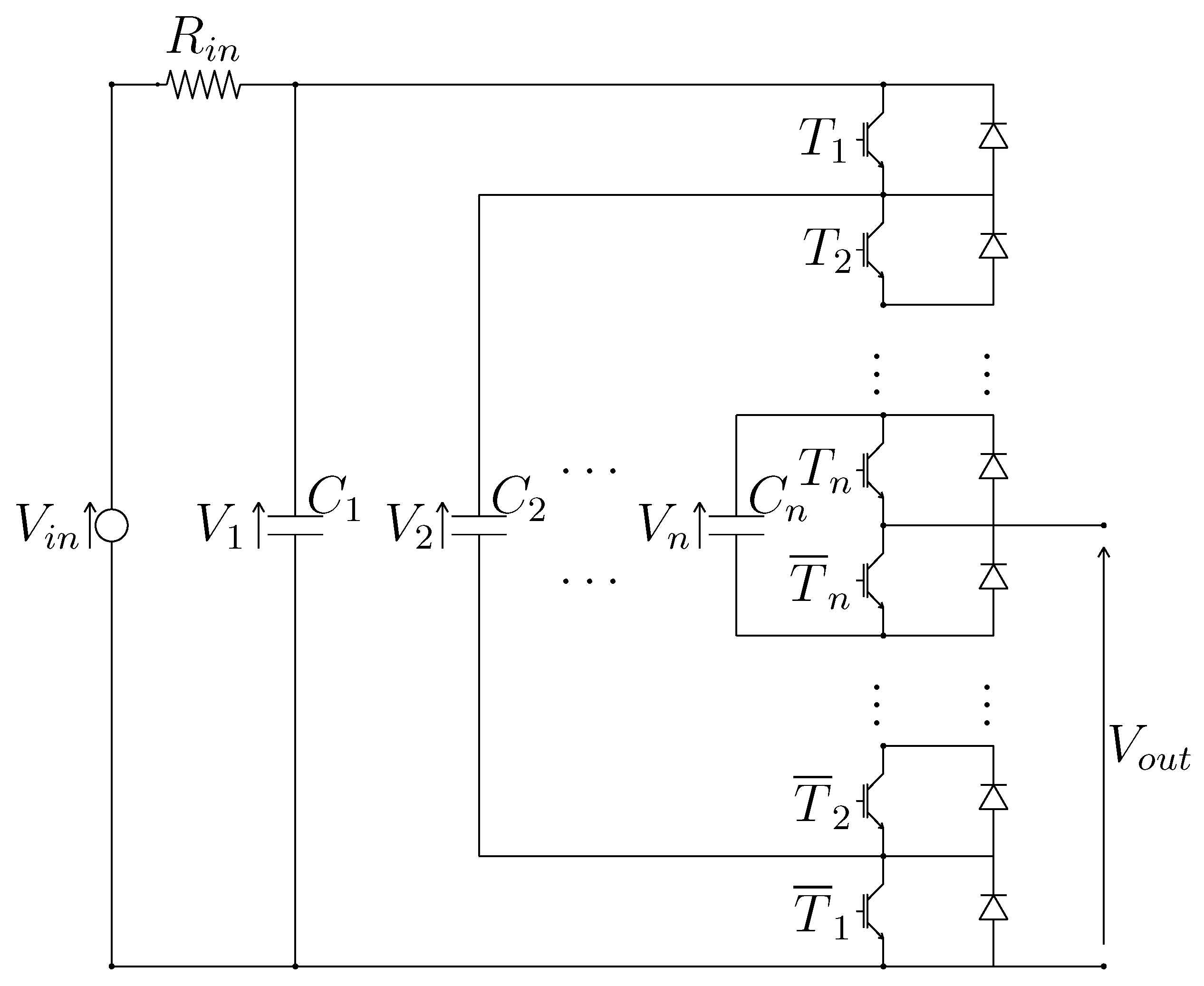
Let us consider the electric scheme of an n-dimensional Multilevel Flying-Capacitor Converter that is shown in Figure 2. The output voltage V o u t is a function of the IGBTs activation signals T i { 0 , 1 } , for i { 1 , 2 , , n } . Let V c and T j denote the capacitors voltage column vector and the IGBTs signal row vectors, defined as follows:
V c = V 1 V 2 V 3 V n , T 0 T 1 T 2 T 3 T m c 2 T m c 1 = 0 0 0 0 0 0 0 1 0 0 1 0 0 0 1 1 1 1 1 0 1 1 1 1 n = 3 T 0 T 1 T 2 T 3 T 4 T 5 T 6 T 7 = 0 0 0 0 0 1 0 1 0 0 1 1 1 0 0 1 0 1 1 1 0 1 1 1 ,
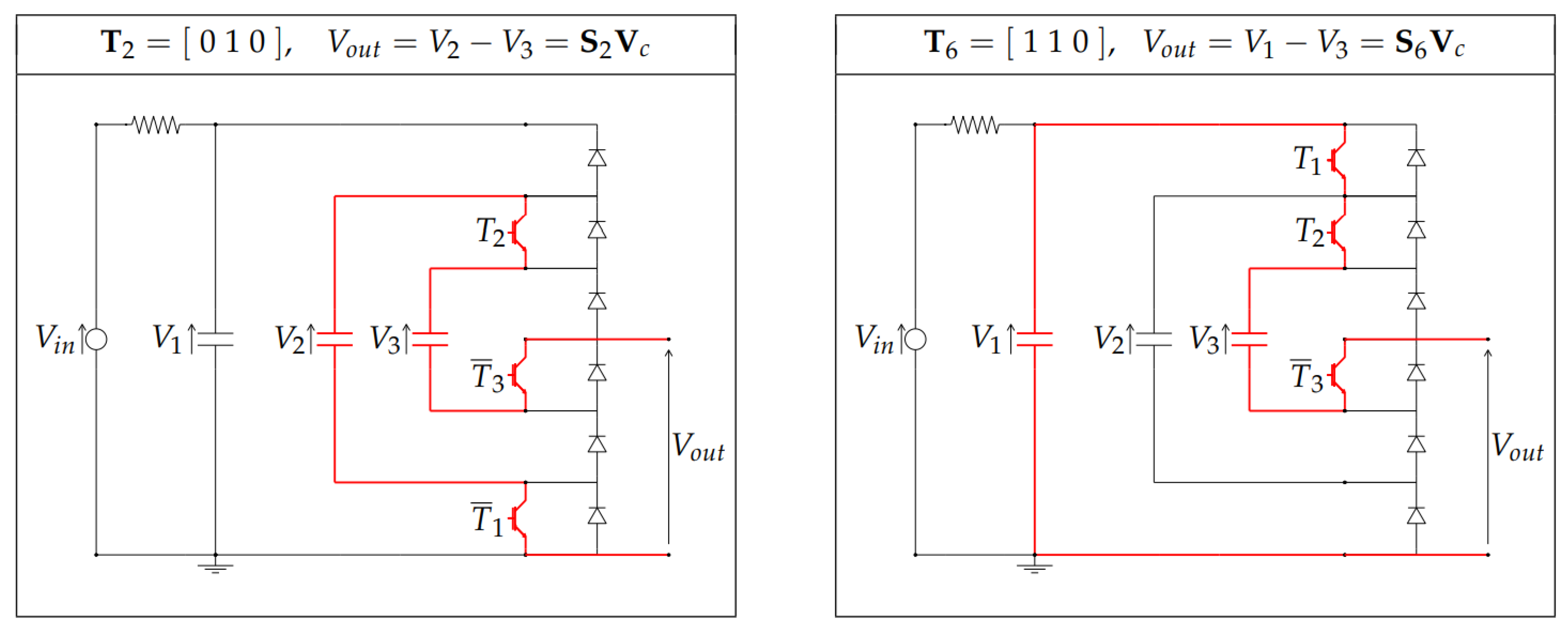
where j { 0 , 1 , , m c 1 } , m c = 2 n , and V i are the voltages across the capacitors C i . The electrical schemes that are reported in Figure 3 show how, for the case n = 3 , the output voltage V o u t is a function of the IGBTs signal vectors T j in the two cases T j = T 2 = [ 0 1 0 ] and T j = T 6 = [ 1 1 0 ] . One can easily verify that the output voltage V o u t can always be expressed as follows:
V o u t = S j V c ,
where S j = s 1 s 2 s n , for j { 0 , 1 , , m c 1 } , are proper configuration vectors. In the two cases of Figure 3, for example, the output voltage V o u t can be expressed as in (2) by using the following two configuration vectors: S 2 = [ 0 1 1 ] and S 6 = [ 1 0 1 ] . Table 2 shows the relations between the IGBTs signal vectors T j , the output voltage V o u t and the configuration vectors S j for the case n = 3 , highlighting the connection between vectors T j and S j . One can verify that the following property holds.
Property 1.
For j { 0 , 1 , , m c 1 } , the components s i { 1 , 0 , 1 } of the configuration vectors S j = s 1 s 2 s n can be obtained from the components T i { 0 , 1 } of the IGBTs signal vectors T j = T 1 T 2 T n , as follows:
s i = T 1 i f i = 1 , T ¯ i 1 T i T i 1 T ¯ i i f i 2 , , n ,
or, equivalently, as follows:
s i = 1 i f T i > T i 1 , 0 i f T i = T i 1 , 1 i f T i < T i 1 ,
for i 1 , 2 , , n and T 0 = 0 .
As an example, the Reader can verify that Property 1 holds for all of the configuration vectors S j that are reported in Table 2 for the case n = 3 . The second last column of Table 2 shows the values of the output voltage V o u t corresponding to the following capacitors voltages V i :
V 1 = V i n , V 2 = 2 V i n 3 , V 3 = V i n 3 V c = V i n 2 V i n 3 V i n 3 .
The last column of Table 2 shows the normalized values α i , as defined in Section 3.3, used for representing the equally spaced values of the output voltage V o u t in the case of n = 3 capacitors and m = 4 output voltage levels.
Let S M denote the matrix containing all of the possible configuration vectors S j , for j { 0 , 1 , , m c 1 } :
S M = S 0 S 1 S m c 1 , if n = 3 S M = S 0 S 1 S 2 S 3 S 4 S 5 S 6 S 7 = 0 0 0 0 0 1 0 1 1 0 1 0 1 1 0 1 1 1 1 0 1 1 0 0 .
Matrix S M can always be rewritten in block matrix form as follows:
S M = 0 S M 0 1 S M 1 if n = 3 S M = 0 0 0 0 0 1 0 1 1 0 1 0 1 1 0 1 1 1 1 0 1 1 0 0 .
One can verify that the block matrices S M 0 , S M 1 R 2 n 1 × ( n 1 ) satisfy the following property.
Property 2.
Let S M 0 j and S M 1 j denote the j-th row of the block matrices S M 0 , S M 1 R 2 n 1 × ( n 1 ) defined in (7). Matrix S M 1 can be obtained from matrix S M 0 , as follows:
S M 1 j = S M 0 2 n 1 + 1 j f o r j 1 , 2 , , 2 n 1 .
Equation (8) means that the rows of matrix S M 1 are equal, with opposite sign, to the rows of matrix S M 0 considered in reverse order.
From Property (2) and Equations (2) and (7), one can verify that the following property holds.
Property 3.
If the output value V o u t 1 = S j V c is obtained using the configuration vector S j , then the following conjugate output value
V o u t 2 = V i n V o u t 1 = S m c j V c
is obtained by employing the configuration vector S m c j , for j 0 , 1 , , m c 1 and m c = 2 n .

3.2. Dynamic Model of the Multilevel Flying-Capacitor Converter

The dynamic model of the Multilevel Flying-Capacitor Converter shown in Figure 2 can be given by using the Power-Oriented Graphs (POG) scheme reported in Figure 4. The corresponding POG state-space equations are the following:
C V ˙ c = A V c S j T I o u t + B V i n , V o u t = S j V c .
Matrices C , A and vectors V c , S j T and B are defined, as follows:
C = C 1 0 0 0 C 2 0 0 0 C n , A = 1 R i n 0 0 0 0 0 0 0 0 , V c = V 1 V 2 V n , S j T = s 1 s 2 s n , B = 1 R i n 0 0 .
A representation such as the one that is shown in (9) and (10) highlights the following interesting features of the system:
  • The energy matrix C groups together the dynamic physical parameters C i for i 1 , 2 , , n , namely the system capacitors.
  • The power matrix A and the input matrix B contain the static physical parameter R i n , which is the system input resistance.
  • The configuration vector S j contains the control signals that directly determine how the output current I o u t is going to charge/discharge the capacitors through I c 0 = S j T I o u t and, at the same time, how the output voltage V o u t is going to be generated from the capacitors voltages through (2).
Therefore, the proposed POG state-space model allows for the parameters within the system matrices to maintain their physical meaning, and also allows to emphasize the presence of the configuration vector S j , representing the output of the two control algorithms that are addressed in Section 4.1 and Section 4.4. The POG block scheme that is shown in Figure 4 presents a graphical representation of the dynamic model of the considered system. The vertical dashed lines ➀, ➁, , and ➄ present in the POG scheme describe the system power sections: the product of the two power variables characterizing the power section has the physical meaning of “power flowing through the considered power section”. The input power P i n = V i n I i n flows through power section ➀ and the output power P o u t = V o u t I o u t flows through power section ➄. The block scheme in between sections ➀ and ➁ describes the static equation of the input resistance R i n , the block scheme in between sections ➁ and ➂ describes the interaction between the input resistance R i n and the capacitors C i , and the block scheme in between sections ➂ and ➃ describes the dynamic equations of the capacitors C i . Finally, the block scheme in between sections ➃ and ➄, which is characterized by the configuration vector S j , describes the interaction between the capacitors C i and the output power section ➄.
Remark 1.
The first vectorial equation of system (9) can be rewritten as follows:
V ˙ c = C 1 A V c C 1 S j T I o u t V ˙ c o u t + C 1 B V i n .
Vector V ˙ c o u t = C 1 S j T I o u t is the component of the velocity vector V ˙ c which is due to the presence of the output current I o u t . The direction of vector V ˙ c o u t is completely defined by the configuration vector S j and by the values of the capacitors C i .
Remark 2.
The first scalar equation of system (9) can be rewritten as follows:
R i n C 1 V ˙ 1 = V i n V 1 R i n s 1 I o u t .
Because the value of the input resistance R i n is typically very low, from (11) it follows that V 1 V i n , that is the value of voltage V 1 tends to remain close to the input voltage value V i n . Hereinafter, the condition V 1 = V i n will be assumed. This condition holds exactly if R i n 0 , or if capacitor C 1 is replaced with a battery providing a constant voltage V i n .

3.3. Calculation of All the Configuration Voltage Vectors

An m-level Multilevel Converter is characterized by m different equally spaced values V o i of the output voltage V o u t :
V o i = i V i n m 1 for i = { 0 , 1 , , m 1 } .
In the following, the values V o i in (12) will often be referred to by using the symbolic integer values α i , defined as follows:
α i = V o i K m = i where K m = V i n m 1 ,
for i = { 0 , 1 , , m 1 } . From (13), it follows that the product α i K m directly gives the values of the corresponding equally spaced values V o i of the output voltage V o u t . All of the possible values V o i of the output voltage V o u t that can be obtained using a particular voltage vector V c can be expressed as follows:
V o = S M V c ,
where S M is the matrix defined in (6). The considered Flying-Capacitor system acts properly as a Multilevel Converter only if vector V o = [ V o 1 , V o 2 , , V o m c ] T contains, among its components V o j , all of the m different equally spaced values V o i given in (12):
i { 0 , 1 , , m 1 } , V o j { V o 1 , V o 2 , , V o m c } | V o j = i V i n m 1 .
Definition 1.
Any voltage vector V c satisfying (14) and (15) will be called a “Configuration Voltage Vector of order m” for the Multilevel Flying-Capacitor Converter.
The problem of finding all the Configuration Voltage Vectors V c of order m for the considered Multilevel Flying-Capacitor Converter can be solved as follows. Dividing (14) by constant K m , one obtains the following symbolic integer relation:
V L = S M V m where V L = V o K m and V m = V c K m .
A vector V m in (16) is a Configuration Voltage Vector of order m only if all the components V L j of vector V L = [ V L 1 , V L 2 , , V L m c ] , for j { 1 , 2 , , m c } , are integer values V L j { 0 , 1 , , m 1 } that satisfy the following relation:
unique ( { V L 1 , V L 2 , , V L m c } ) = { 0 , 1 , , m 1 } ,
where “ unique ( S ) ” is a function providing a new set containing all the elements of set S which are different from each other.
Property 4.
In (16), all of the components β i of a Configuration Voltage Vector V m , for i { 1 , , n } , are integer values satisfying β i { 0 , 1 , , m 1 } :
V m = β n β n 1 β 1 = m 1 β n 1 β 1 ,
where β i + 1 β i for i { 1 , 2 , , n 2 } . Furthermore, note that the top component β n of vector V m is always given by β n = m 1 .
The first statement of Property 4 holds true, because: (1) all of the components V L j of vector V L in (16) are integer values, see (17); and, (2) the configuration vectors S 1 = [ 0 , 0 , 0 , 1 ] , S 2 = [ 0 , 0 , 1 , 0 ] , S 3 = [ 0 , 1 , 0 , 0 ] , , S m c = [ 1 , 0 , 0 , 0 ] are always present among the rows of matrix S M . The second statement of Property 4 holds true, because the top component β n of vector V m is always equal to the first component V 1 of vector V c expressed in symbolic integer form: β n = V 1 / K m = V i n / K m = m 1 , see (13). This relation holds thanks to the assumption V 1 = V i n made in Remark 2.
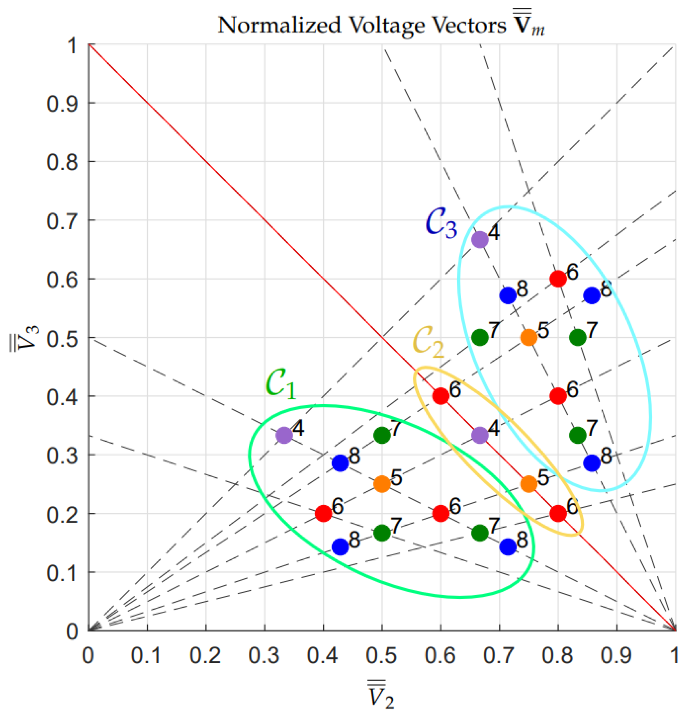
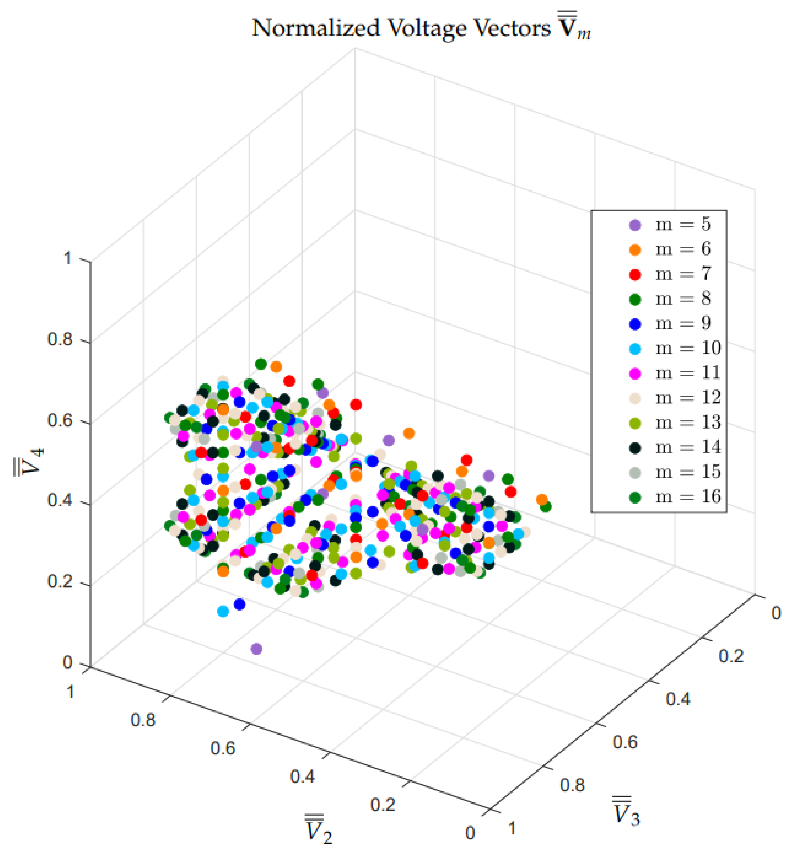
Thanks to Property 4, all of the Configuration Voltage Vectors V m of order m for the considered Multilevel Flying-Capacitor Converter can be found by making an exhaustive research in (18) for β i { 0 , 1 , , m 1 } , and keeping all of the solutions V m that satisfy (16) and (18). Table 3 reports all of the Configuration Voltage Vectors V m for the case n = 3 and for m { 4 , 5 , , 8 } . The total number N c of Configuration Voltage Vectors for the case n = 3 is N c = 24 . Figure 5 shows a graphical representation of the normalized form V ¯ ¯ m of all the Configuration Voltage Vectors V m for the case n = 3 . The normalized form V ¯ ¯ m of the Voltage Vectors V m defined in (18) is obtained as follows:
V ¯ ¯ m = V m ( 2 : end ) m 1 = β n 1 m 1 β 1 m 1 = V ¯ ¯ 2 V ¯ ¯ n if n = 3 V ¯ ¯ m = V ¯ ¯ 2 V ¯ ¯ 3 ,
meaning that the last n 1 components of vector V m , from the second to the last one, are normalized by m 1 . Figure 5 clearly shows a symmetry with respect to the red straight line V ¯ ¯ 3 = 1 V ¯ ¯ 2 . This symmetry is strictly connected to Property 5 and Property 6, introduced in the following.
Property 5.
For every Configuration Voltage Vector V m , there exists a Conjugate Configuration Voltage Vector V m , defined as follows:
V m = m 1 β n 1 β 2 β 1 V m = m 1 m 1 β 1 m 1 β 2 m 1 β n 1 .
Furthermore, one can easily verify that ( V m ) = V m . This property directly follows from Property 3.
Property 6.
Every Configuration Voltage Vector V m , see (20), is characterized by a configuration number N β , defined as follows:
N β = i = 1 n 1 β i .
The set C of all the Configuration Voltage Vectors V m can be divided into three different subsets, which are denoted by C 1 , C 2 , and C 3 , defined as follows:
C 1 = { V m C | N β < m 1 } , C 2 = { V m C | N β = m 1 } , C 3 = { V m C | N β > m 1 } .
The sets C 1 and C 3 are conjugate to one another: if V m C 1 , then V m C 3 and vice versa. Furthermore, set C 2 is conjugate to itself: if V m C 2 , then V m = V m .
Note: Table 3 has been given, for each number of output voltage levels m, in ascending order from left to right with respect to the configuration number N β . Additionally, the colors that are present in Table 3 denote the subsets to which the Configuration Voltage Vectors V m belong: green color if V m C 1 , yellow color if V m C 2 , and blue color if V m C 3 . The same color notation has been adopted in Figure 5 to identify the subsets to which the normalized forms V ¯ ¯ m of the Configuration Voltage Vectors V m belong, which are highlighted by the colored ellipses.
The number N c of Configuration Voltage Vectors V m for the case n = 4 is N c = 407 . Figure 6 shows a graphical representation of the normalized form V ¯ ¯ m of all the Configuration Voltage Vectors V m for the case n = 4 . The considerations that are introduced in Property 5 and Property 6 also apply to the set of all the Configuration Voltage Vectors V m for the cases n = 4 , n = 5 , etc.
The number N c of the Configuration Voltage Vectors V m increases very rapidly by increasing n, with a rate faster than exponential: N c = 24 for n = 3 , N c = 407 for n = 4 , N c = 14,252 for n = 5 , N c = 1,044,305 for n = 6 , etc.

3.4. Model Verification

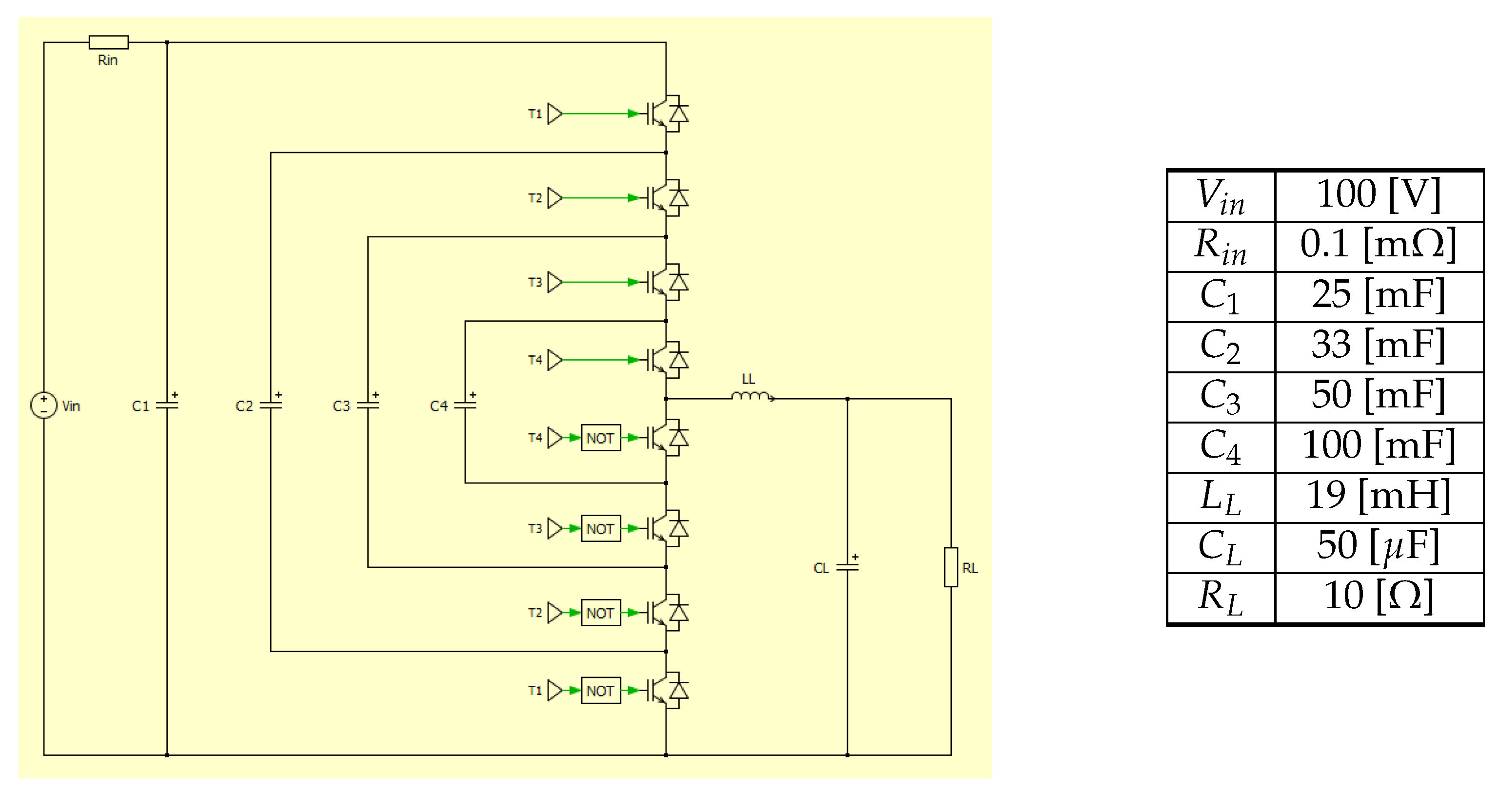
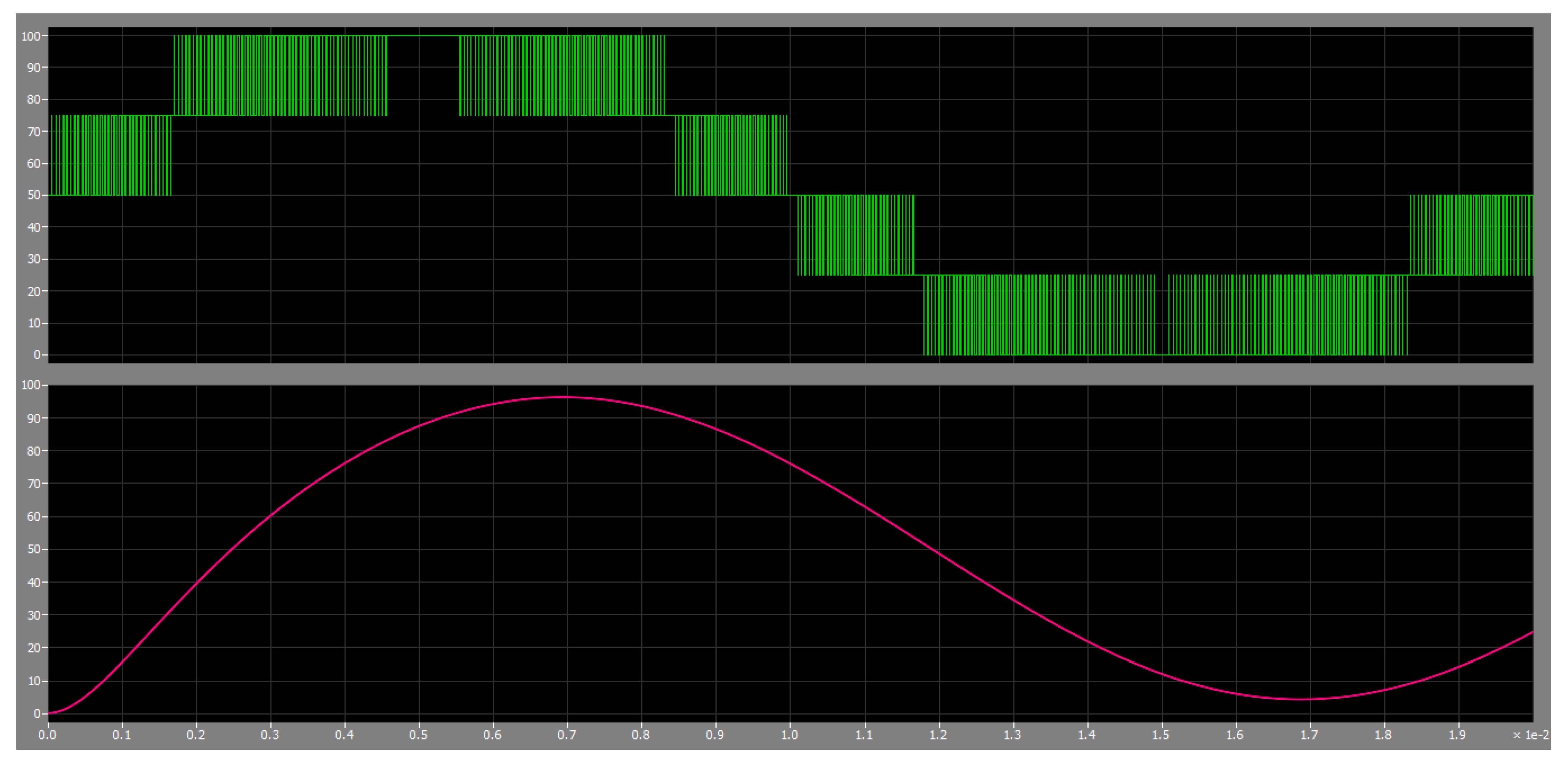
The model of the multilevel flying-capacitor converter proposed in Figure 4 has been tested in simulation against one of the most well-known platforms for the simulation of power electronics systems, namely PLECS, in order to perform a model verification. For this comparative simulations, the case n = 4 and V m = [ 4 3 2 1 ] T has been considered to be a case study. Figure 7 reports the PLECS model and the system parameters. The initial and desired voltages for the multilevel converter capacitors can be determined by computing the voltage vector V c starting from the configuration voltage vector V m and using (13) and (16), namely V c = [ 100 75 50 25 ] T . The initial conditions of the RLC load are assumed to be equal to zero. The desired voltage V d is assumed to be sinusoidal with an offset equal to V i n / 2 , a peak-to-peak amplitude equal to V i n and a frequency equal to 50 Hz. The simulation performed using the PLECS model in Figure 7 and the simulation performed using the Matlab/Simulink POG model in Figure 4 have both been performed applying the Minimum Distance Control described in Section 4.1.
The results that are given by the PLECS model are shown in Figure 8. The comparison of these results with those given by the Matlab/Simulink POG model is reported in Figure 9.
The very good matching between the output voltage characteristics that are given by PLECS and by Matlab/Simulink in Figure 9 verifies the correctness of the proposed model of the multilevel flying-capacitor converter.

4. Control of the Multilevel Flying-Capacitor Converter

4.1. Minimum Distance Control

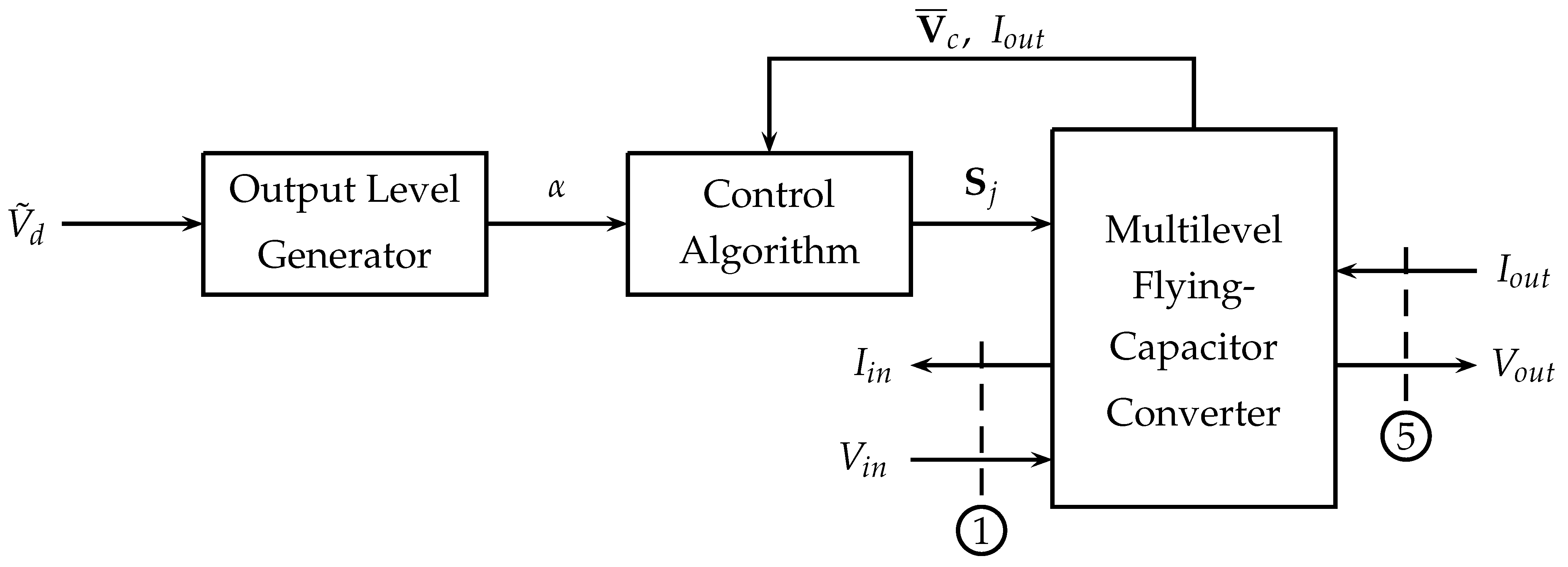
Figure 10 shows the typical scheme of a closed-loop Minimum Distance Control of a Multilevel Flying-Capacitor Converter. The first block of the scheme is the Output Level Generator. Let us consider the case of m = 6 output voltage levels, which will, therefore, be equally spaced between level “0” and level “ m 1 = 5 ”. The black characteristic in Figure 11 shows the desired normalized voltage V ˜ d multiplied by m 1 , in order to see it superimposed to the blue characteristic, namely the desired output voltage level α.
The Output Level Generator generates an integer value α { 0 , 1 , , m 1 } , which defines the desired output level to be applied at a certain time instant t k :
α = h = 0 m 1 ( V d V c r h ) ,
where ( V d V c r h ) = 1 if V d V c r h and ( V d V c r h ) = 0 if V d < V c r h . The second and third blocks in the scheme of Figure 10 are the Control Algorithm and the Multilevel Flying-Capacitor Converter. The latter is modeled using the POG block scheme that is shown in Figure 4. Indeed, it is possible to notice the correspondence between the power sections ➀ and ➄ in Figure 4 and Figure 10. The purpose of the Control Algorithm is to properly generate the Configuration Voltage Vector S j , which has a one-to-one correspondence with the IGBTs signal vector T j through Property 1, giving the desired output level α . This will be accomplished by exploiting the redundance of Configuration Voltage Vectors S j generating the same desired output level α when available, as described in the remainder of this section. The Control Algorithm shown in Figure 10 is typically a “Minimum Distance Algorithm”. Thanks to the assumption V 1 = V i n made in Remark 2, the Minimum Distance algorithm only applies to the components V 2 , V 3 , , V n of the capacitors voltage vector V c . Let us denote, as V ¯ c = V c ( 2 : n ) , V ¯ m 0 = K m V m ( 2 : n ) = V i n V ¯ ¯ m and S ¯ C j = S j ( 2 : n ) . / C ( 2 : n ) , the following reduced vectors:
V ¯ c = V 2 V 3 V n , V ¯ m 0 = V i n β n 1 m 1 V i n β n 2 m 1 V i n β 1 m 1 , S ¯ C j = s 2 j C 2 s 3 j C 3 s n j C n ,
where V m is the considered Configuration Voltage Vector that is introduced in (16), and S j is the j-th configuration vector defined in (10). The minimum distance algorithm tries to keep the reduced voltage vector V ¯ c as close as possible to the desired reduced voltage vector V ¯ m 0 . Let α be the desired output level to be applied at time t k and let
S α = j | j [ 0 , 1 , , m c 1 ] S j V c = α V i n m 1
be the set of the indexes j of all the configuration vectors S j , which, for the considered Configuration Voltage Vector V m , provide the output level α . The Minimum Distance algorithm acts as follows:
  • At instant t k , read the value of the reduced voltage vector V ¯ c ( t k ) ;
  • For any j S α , compute the new position V ¯ c j ( t k + T W ) of the reduced voltage vector V ¯ c at instant t k + T W , which is due to the application of the configuration vector S j :
    V ¯ c j ( t k + T W ) = V ¯ c ( t k ) + S ¯ C j I o u t T W Δ S ¯ C j = V ¯ c ( t k ) + Δ S ¯ C j ,
    where I o u t is the value of the output current at instant t k and T W is the time for which the configuration vector S j is applied.
  • For any j S α , compute the following distance vectors:
    Δ V ¯ c j = V ¯ c j ( t k + T W ) V ¯ m 0
    between points V ¯ c j ( t k + T W ) and the desired reduced Voltage Vector V ¯ m 0 .
  • At instant t k , apply the configuration vector S j * , with j * S α , for which the norm of vectors Δ V ¯ c j is minimized:
    S j * such that | Δ V ¯ c j * | | Δ V ¯ c j | f o r j S α .
Figure 12 shows a graphical example of how the Minimum Distance algorithm works in the case of n = 3 , m = 4 , V m = [ 3 2 1 ] T when the desired output level is α = 1 . In this case, the distance vector Δ V ¯ c j in (25) having the minimum norm is | Δ V c 4 | , highlighted in magenta in the figure.

4.2. Basic Configurations

For any n-dimensional multilevel flying-capacitor converter, let us denote, as Basic Configuration Voltage Vector, the following Configuration Voltage Vector:
V m * = m 1 m 2 2 1 T ,
occurring when m = n + 1 .
Property 7.
For any given n, the basic configuration voltage vector V m * is the only configuration voltage vector for which the Minimum Distance algorithm is able to keep the reduced voltage vector V ¯ c in the neighborhood of the desired reduced voltage vector V ¯ m 0 * , for any value of the normalized desired voltage V ˜ d and the output current I o u t .
This property holds because the Basic Configuration Voltage Vector V m * is the only one for which the number of possible configurations S j that are associated to the two adjacent levels of any desired voltage V d are sufficient to guarantee that, at each PWM step, the distance between the reduced vector V c and the desired reduced voltage vector V m 0 * is decreased for any value of the output current I o u t . For any other Configuration Voltage Vector V m , it is always possible to find values for V d and I o u t causing the reduced vector V c to indefinitely diverge from the desired reduced voltage vector V m 0 .
Figure 13 shows a first example of the validity of Property 7, for the case n = 3 and V m * = [ 3 2 1 ] T . In this figure, a certain number of trajectories in the space ( V 2 , V 3 ) starting from initial conditions that are distant from the desired reduced voltage vector V ¯ m 0 are shown. Red asterisks in the figure denote the considered initial conditions. The trajectories have been obtained using the Minimum Distance algorithm and using the following input signals:
V d = V i n 2 + V i n 2 sin ( 800 π t ) , I o u t = 10 A , V i n = 1 V .
The figure clearly shows that all of the trajectories asymptotically tend to the desired reduced voltage vector V ¯ m 0 = [ 0.66 0.33 ] T .
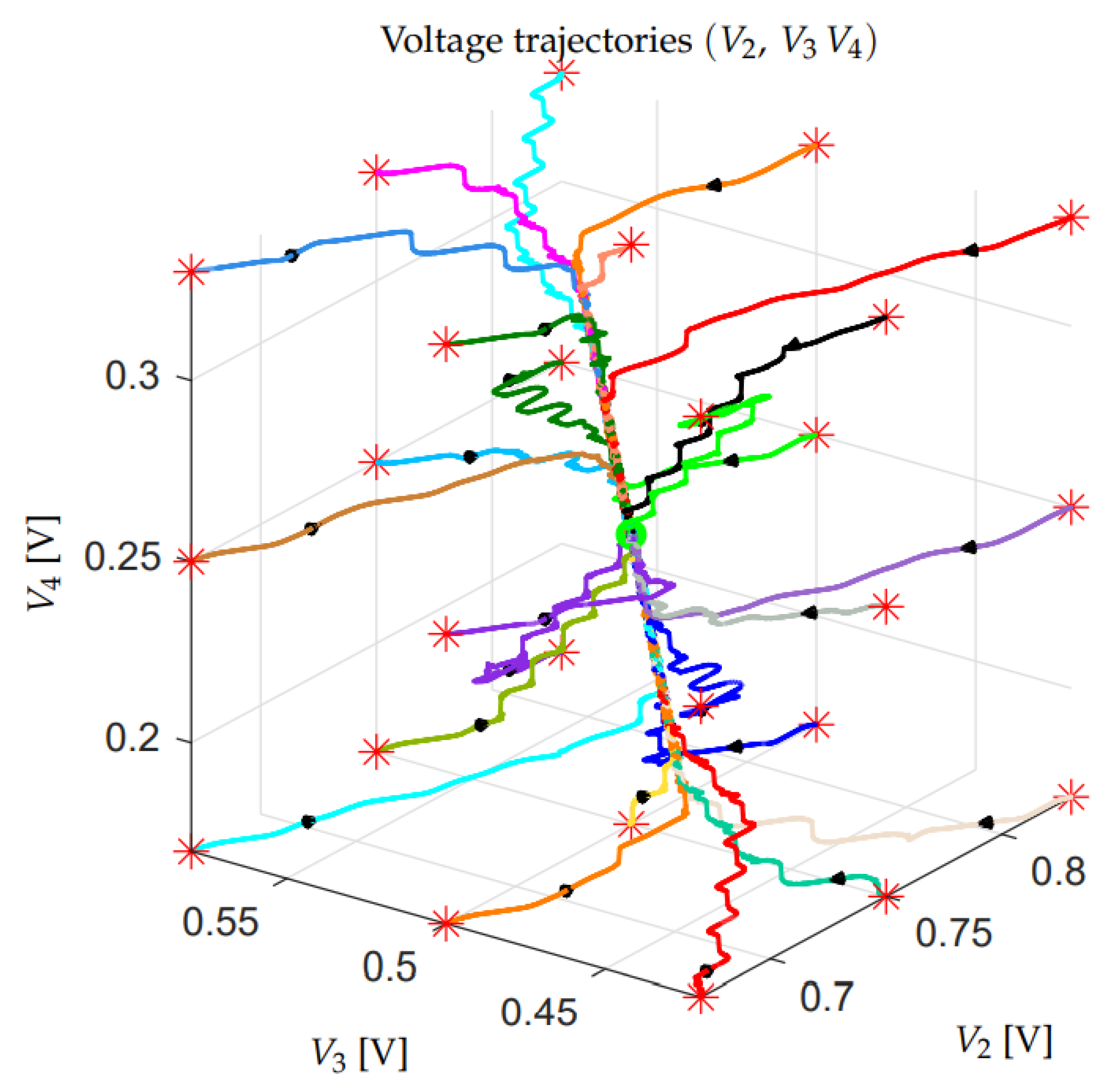
A second similar example is given in Figure 14 for the case n = 4 and V m * = [ 4 3 2 1 ] T . The three-dimensional trajectories in the space ( V 2 , V 3 , V 4 ) have been obtained using the same input signals (28) that were used for the previous example. Even in this case, one can notice that all of the trajectories asymptotically tend to the desired reduced voltage vector V ¯ m 0 = [ 0.75 0.5 0.25 ] T .

4.3. Robustness Assessment of the Configuration Voltage Vectors

All of the Configuration Voltage Vectors V m different from the basic one V m * are characterized by divergent voltage trajectories under particularly unfavorable operating conditions, as stated in Property 7. In Figure 15 and Figure 16, for example, the voltage trajectories that are associated with two different Configuration Voltage Vectors V m in the space ( V 2 , V 3 ) for the case n = 3 are reported, starting from different initial conditions that are distant from the desired reduced voltage vector V ¯ m 0 . The considered initial conditions are denoted by red asterisks in the figures. The trajectories shown in Figure 15 have been obtained using V m = [ 5 4 3 ] T , V ¯ m 0 = [ 0.8 0.6 ] T , V d = 0.3 V and I o u t = 10 A. The trajectories in Figure 16 have been obtained using V m = [ 5 3 2 ] T , V ¯ m 0 = [ 0.6 0.4 ] T , V d = 0.7 V and I o u t = 10 A. In both cases, after a transient, all of the trajectories tend to diverge along a particular direction, which is characteristic of the considered Configuration Voltage Vectors V m . One can verify that the same qualitative behavior is obtained for any V m different from the Basic Configuration Voltage Vector V m * .
From the previous considerations, the need to find a criterion to evaluate the degree of divergence of the different Configuration Voltage Vectors V m arises. For this purpose, a Vectorial Divergence Function V m ( V ˜ d ) can be defined for each V m . Before giving the definition of this function, the following preliminary material needs to be introduced.
  • Given the Configuration Voltage Vectors V m = [ m 1 β n 1 β 2 β 1 ] T and the value of the last n-th capacitor C n , let us choose the values of the remaining n 1 capacitors C 1 , C 2 , , C n 1 , as follows:
    C 1 = β 1 C n m 1 , C 2 = β 1 C n β n 1 , , C n 2 = β 1 C n β 3 , C n 1 = β 1 C n β 2 ,
    namely, each capacitor C i is chosen inversely proportional to the components of vector V m .
  • The Minimum Distance Algorithm that is given in Section 4.1 can be rewritten in an equivalent form by using the following Matlab-like function “ [ S j , Δ V ¯ ] = MDA ( Δ V ¯ , α , I o u t , T W ) ”, which must be called providing Δ V ¯ = V ¯ c ( t k ) V ¯ m 0 :
function [ S j , Δ V ¯ ] = MDA ( Δ V ¯ , α , I o u t , T W )
Compute set S α defined in (23);
Compute vectors S ¯ C j defined in (22) using (29);
for j S α
     Compute Δ V ¯ c j as follows, see (25):
     Δ V ¯ c j = Δ V ¯ + S ¯ C j I o u t T W ;
end
Find j * S α for which the norm of vectors Δ V ¯ c j is minimized, as in (26);
Set S j = S j * ;
Set Δ V ¯ = Δ V ¯ c j * ;
Definition 2.
Given a Configuration Voltage Vector V m , the corresponding Vectorial Divergence Function V m ( V ˜ d ) is defined, by employing a Matlab-like notation, as follows:
I o u t = 1 ;% Function normalized with respect to I o u t
T P W M = 1 ;% Function normalized with respect to time
C n = 1 ;% Function normalized with respect to C n
for V ˜ d = ( 0 : 1 / N P o i n t s : 1 ) % N P o i n t s of variable V ˜ d [ 0 , 1 ]
     V D = V ˜ d ( m 1 ) ; % N P o i n t s of variable V D [ 0 , m 1 ]
     α H = c e i l ( V D ) ;% Upper adjacent level
     α L = f l o o r ( V D ) ; % Lower adjacent level
     d c = V D α L ; % Duty cycle of the upper level
     Δ V ¯ = 0 ; % Zero initial condition
     for h = 1 : N S t e p s % Repeat N S t e p s times
          T W = d c T P W M % Time interval of the upper level
          [ , Δ V ¯ ] = MDA ( Δ V ¯ , α H , I o u t , T W ) ; % Upper level Minimum Distance Algorithm
          T W = ( 1 d c ) T _ P W M % Time interval of the lower level
          [ , Δ V ¯ ] = MDA ( Δ V ¯ , α L , I o u t , T W ) ; % Lower level Minimum Distance Algorithm
     end
     V m ( V ˜ d ) = Δ V ¯ / N S t e p s ; % Function V m is defined in point V ˜ d
end
The precision of calculation of function V m ( V ˜ d ) increases if the values of parameters N P o i n t s and N S t e p s increase. The Vectorial Divergence Function V m ( V ˜ d ) satisfies the following properties.
Property 8.
The Vectorial Divergence Function V m ( V ˜ d ) of all the Basic Configuration Voltage Vectors V m * is zero for any value of variable V ˜ d = [ 0 1 ] :
V m ( V ˜ d ) = 0 f o r V ˜ d = [ 0 , 1 ] .
This property holds as a direct consequence of Property 7.
Property 9.
The Vectorial Divergence Function V m ( V ˜ d ) satisfies the following symmetry with respect to the value V ˜ d = 0.5 :
V m ( V ˜ d ) = V m ( 1 V ˜ d ) , f o r V ˜ d [ 0 , 0.5 ] .
This property holds as a direct consequence of Property 3. Property 9 implies the symmetry of the Vectorial Divergence Function V m ( V ˜ d ) with respect to the origin. Figure 17 gives an example showing two different graphical representations of the Vectorial Divergence Function V m ( V ˜ d ) that is associated with all of the Configuration Voltage Vectors V m for the case n = 3 , N P o i n t s = 400 and N S t e p s = 200 . The left subplot shows the norm | V m ( V ˜ d ) | of the Vectorial Divergence Function versus V ˜ d [ 0 , 0.5 ] . The function | V m ( V ˜ d ) | has not been plotted for V ˜ d [ 0.5 , 1 ] , because of the symmetry defined in Property 9. The right subplot of Figure 17 shows the Vectorial Divergence Function V m ( V ˜ d ) on plane ( V 2 , V 3 ) . This subplot clearly shows the symmetry of function V m ( V ˜ d ) with respect to the origin, as stated in Property 9. The two digit numbers “ m . i ”, which are present for each characteristic in the two subplots of Figure 17, denote the number m of output levels and the order i of the Configuration Voltage Vector V m of the nearby colored line, according to the order and the colors reported in Figure 18. The two subplots of Figure 17 clearly show that the norm | V m ( V ˜ d ) | of the Vectorial Divergence Function V m ( V ˜ d ) tends to increase with the number m of the output levels and, therefore, it can be used as a starting point to estimate the degree of divergence and, thus, the degradation of the voltage balancing capability, associated to the corresponding Configuration Voltage Vector V m . For this purpose, let us define the following Divergence Index.
Definition 3.
The Divergence Index I M of a Configuration Voltage Vector V m is defined as follows:
I M = max | V m ( V ˜ d ) | ,
namely as the maximum value of the norm | V m ( V ˜ d ) | of the Vectorial Divergence Function V m ( V ˜ d ) .
The larger the Divergence Index I M , the less robust is the corresponding Configuration Voltage Vector V m . Therefore, the Divergence Index I M is inversely proportional to the degree of robustness of the corresponding Configuration Voltage Vector V m . For all of the Basic Configuration Voltage Vectors V m * , the Divergence Index I M is zero, according to Property 8. Index I M can also be used to provide a new sorting for the Configuration Voltage Vectors V m having the same number m of output levels. Figure 18 shows the new sorting, in ascending order of the Divergence Index I M for each vector V m having the same number m of output voltage levels. Therefore, the different Configuration Voltage Vectors V m having the same number m of output levels are sorted in decreasing degree of robustness when moving from left to right in Figure 18. The magenta line that is reported in Figure 18 is the Mean Index I m of the Configuration Voltage Vectors V m . The Mean Index I m is defined as the mean value of the norm | V m ( V ˜ d ) | of the Vectorial Divergence Function V m ( V ˜ d ) : I m = m e a n | V m ( V ˜ d ) | . Figure 18 clearly shows a strong correlation between the Divergence Index I M and Mean Index I m .
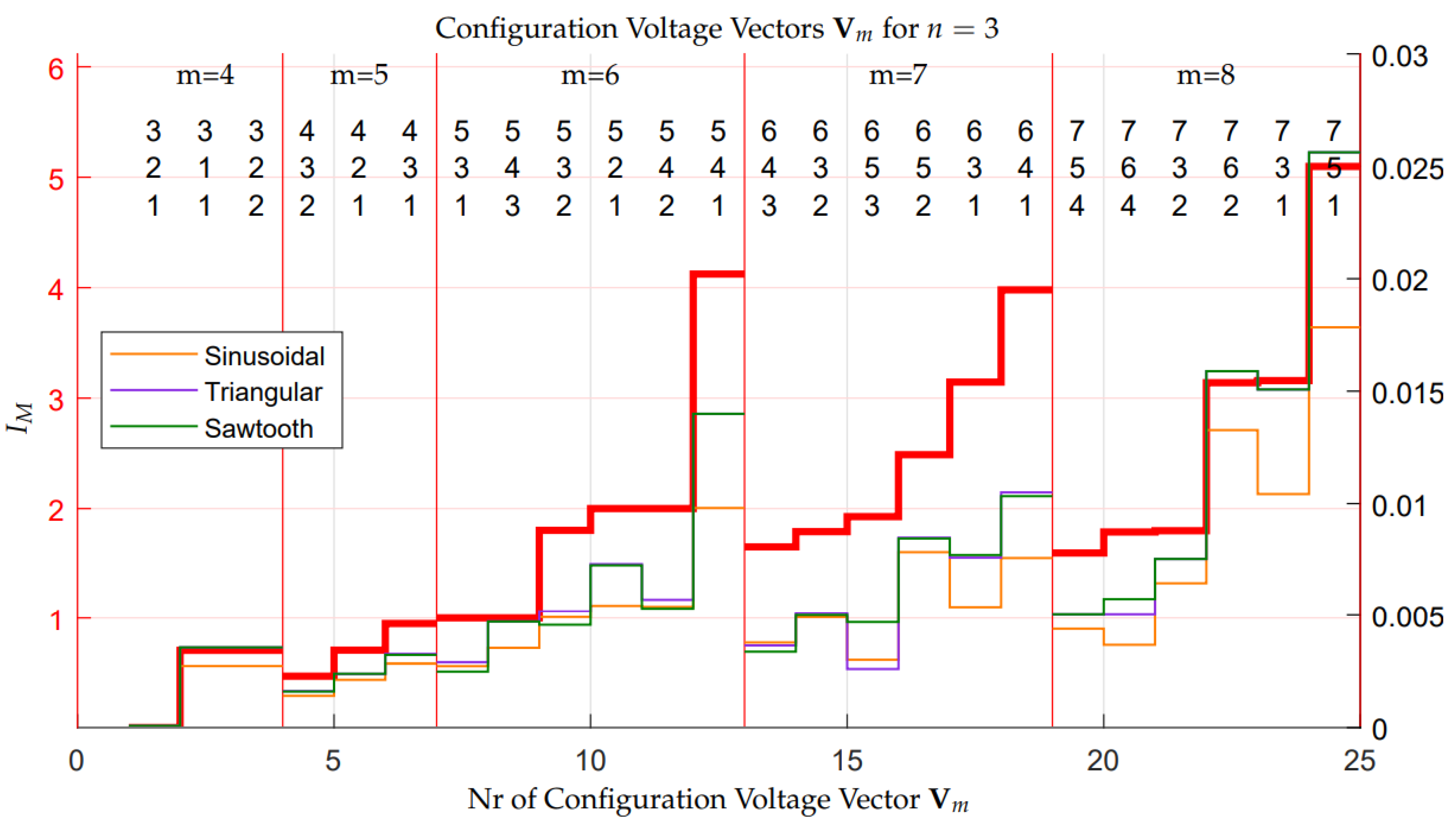
In order to verify the correctness of the sorting proposed in Figure 18, all of the Configuration Voltage Vectors V m , for n = 3 , have been tested in simulation using the three types of voltage signals V d that are shown in Figure 19 (sinusoidal, triangular, and sawtooth) with V i n = 1 V , an offset equal to V i n / 2 , a peak-to-peak amplitude equal to V i n , a frequency equal to 50 Hz, an output current equal to I o u t = 1 A , and capacitors C i chosen as in (29) with C n = 1 F . Figure 20 shows the results of these simulations, where the Divergence Index I M (red characteristic, left vertical axis) is compared with the maximum norm max ( | Δ V ¯ | ) of vectors Δ V ¯ = V ¯ c ( t ) V ¯ m 0 obtained in simulation for the three types of the considered periodical signals (colored characteristics, right vertical axis). Two different reference axes have been used in Figure 20, because the Vectorial Divergence Function V m ( V ˜ d ) and corresponding Divergence Index I M have been computed using a constant normalized voltage V ˜ d [ 0 , 1 ] , whereas the maximum norms max ( | Δ V ¯ | ) have been obtained in simulation using different signals, i.e., periodical normalized signals V ˜ d with a non-zero frequency of 50 Hz. It can be shown that the two quantities I M and max ( | Δ V ¯ | ) would tend to be comparable only if the frequency of the periodical normalized signals V ˜ d became equal to zero. Consequently, the Divergence Index I M represents an upper boundary for the maximum norm index max ( | Δ V ¯ | ) , for each Configuration Voltage Vector V m . Furthermore, Figure 20 shows the good direct proportionality existing between the Divergence Index I M and the maximum norm indices max ( | Δ V ¯ | ) of the three considered signals. This good proportionality shows the effectiveness of using the Divergence Index I M for evaluating the divergence characteristics of the different Configuration Voltage Vectors V m , which gives a direct measurement of their degree of robustness.
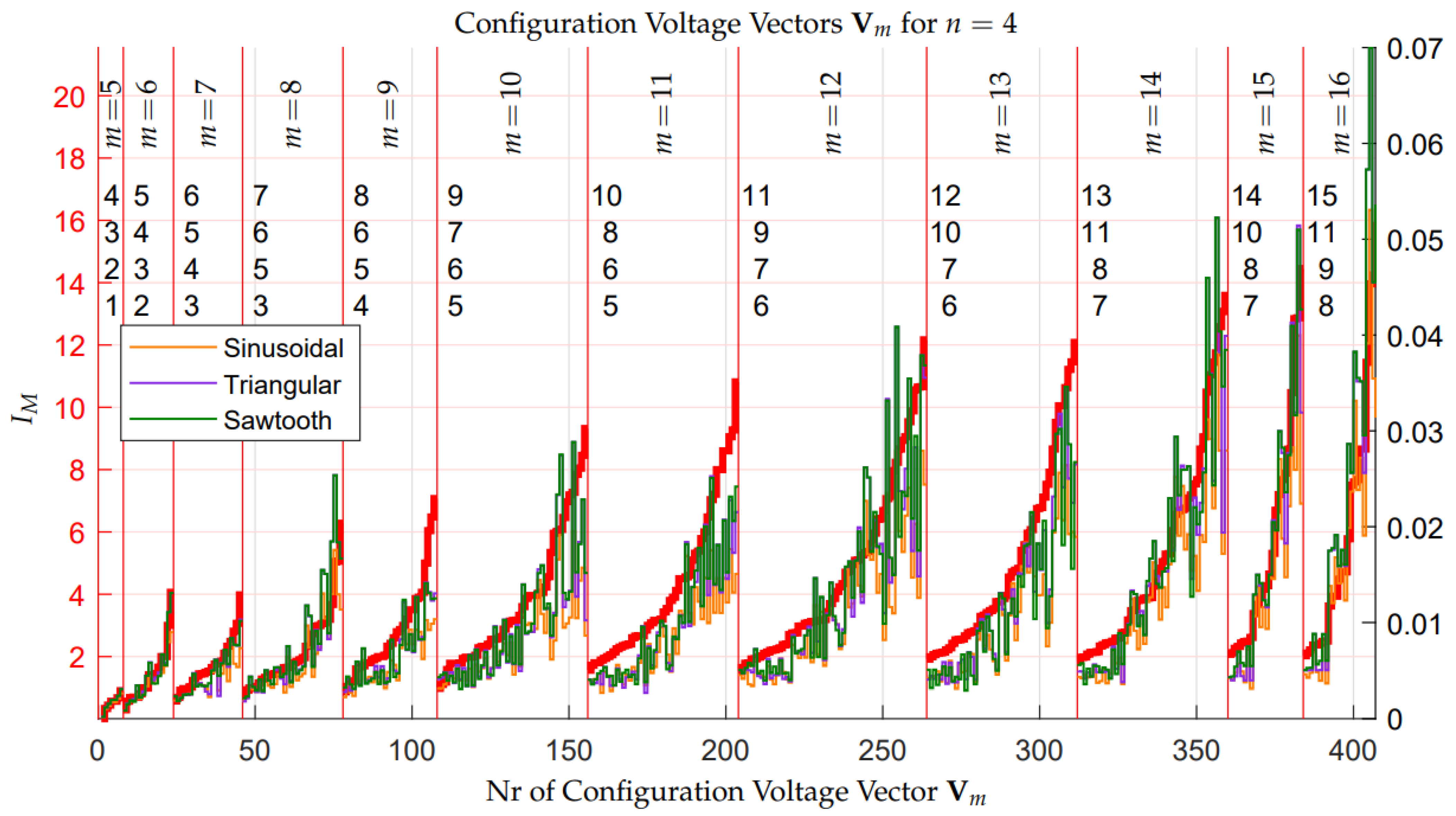
Even for the case n = 4 , all the Configuration Voltage Vectors V m have been tested in simulation by employing the same normalized periodical signals V ˜ d used for the case n = 3 , which are shown in Figure 19. Figure 21 reports the results of these simulations and the comparison between the Divergence Index I M (red characteristic, left vertical axis) and the maximum norm indices max ( | Δ V ¯ | ) (colored lines, right vertical axis). In this figure, the 407 Configuration Voltage Vectors V m of case n = 4 have been sorted with respect to the Divergence Index I M . The upper part of the figure shows, for each m [ 5 , 6 , , 16 ] , the Configuration Voltage Vector V m having the minimum Divergence Index I M . The simulation results that are reported in Figure 21 show the good direct proportionality existing between the Divergence Index I M and the maximum norm indices max ( | Δ V ¯ | ) , even in the case n = 4 , and, therefore, the effectiveness of using the Divergence Index I M for evaluating the divergence characteristics, i.e., the degree of robustness, of the different Configuration Voltage Vectors V m .

4.3.1. Minimum Distance Control: Stability Issues in Extended Operation

The analysis performed on the basis of the Vectorial Divergence Function V m ( V ˜ d ) has shown that all of the Configuration Voltage Vectors V m , other than the basic one V m * , are unstable with different degrees of divergence in some unfavorable conditions, such as constant desired voltage V ˜ d , while using the Minimum Distance algorithm. Moreover, Figure 20 and Figure 21 have shown that, for some periodical desired signal V ˜ d with an average value equal to 0.5 , the maximum distance max ( Δ V ¯ ) of the voltage vector V ¯ c from the desired voltage vector V ¯ m 0 remains bounded. The amplitude of the maximum distance max ( Δ V ¯ ) increases if the output current I o u t increases, and it decreases if capacitor C n or the frequency of the periodical signal V ˜ d increase.
If V ¯ c remains in the vicinity of the desired voltage vector V ¯ m 0 , then the multilevel converter works properly, providing an output signal V o u t switching between equally spaced voltage values. On the contrary, if the maximum distance max ( Δ V ¯ ) increases excessively, then the output values S M V c of the multilevel converter will no longer be equally spaced and the average value of the output switching signal V o u t will no longer be equal to the desired signal V i n V ˜ d . If this situation occurs, the multilevel converter cannot work properly, because it provides output signals that are not equal to the desired ones. The output voltage error V e r r = V o u t V i n V ˜ d remains low and, therefore, acceptable, only if the maximum distance max ( Δ V ¯ ) remains sufficiently low. Unfortunately, in practical applications, such as the electric motors control, it can happen that the desired voltage vector V ˜ d does not have an average value equal to 0.5. In this condition, vector V ¯ c diverges from the desired voltage vector V ¯ m 0 , which means that the output voltage error V e r r increases excessively and the multilevel converter can no longer work correctly. Another destabilizing condition can be identified in a sudden load change. These two scenarios are considered in the following two simulation case studies:
(A)
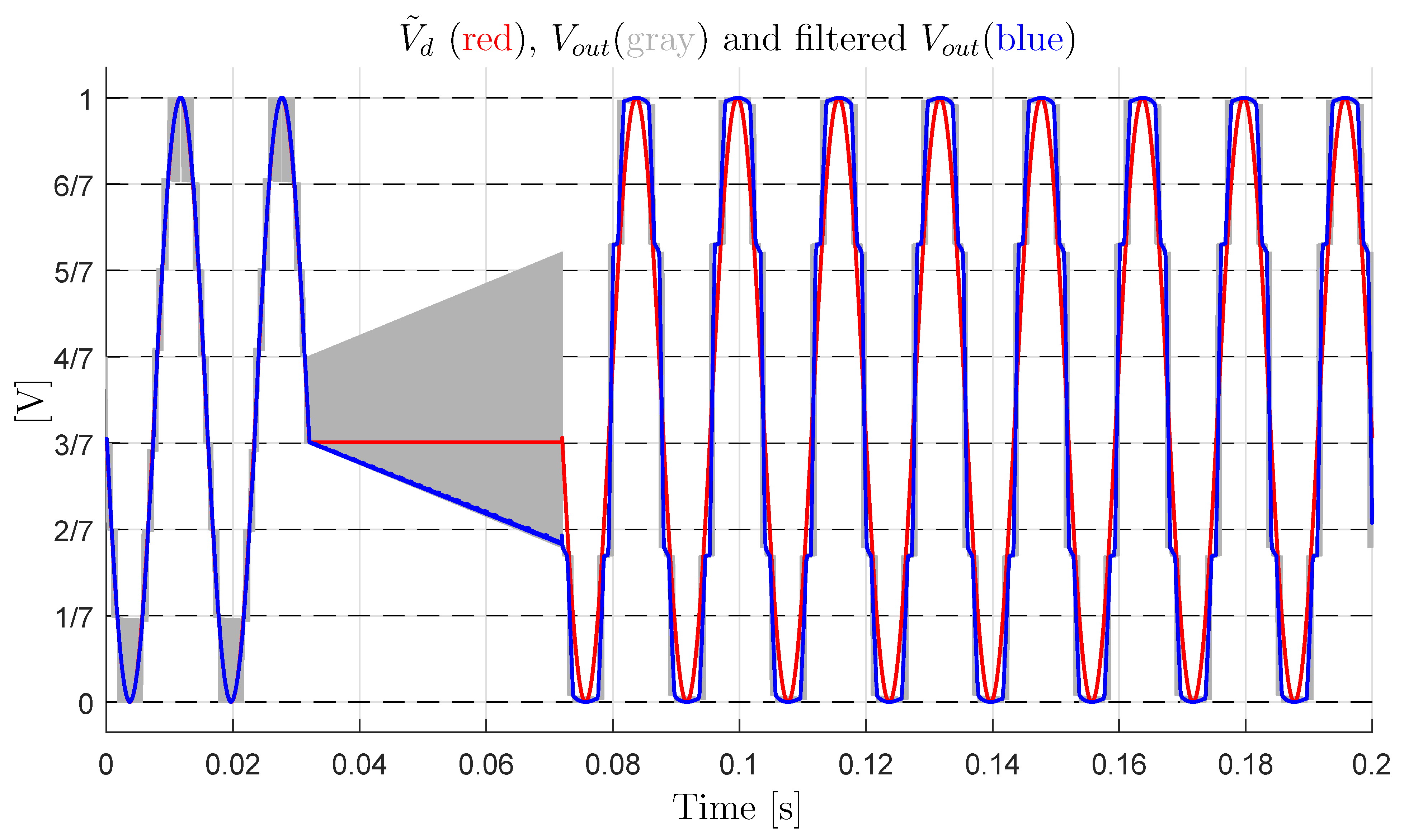
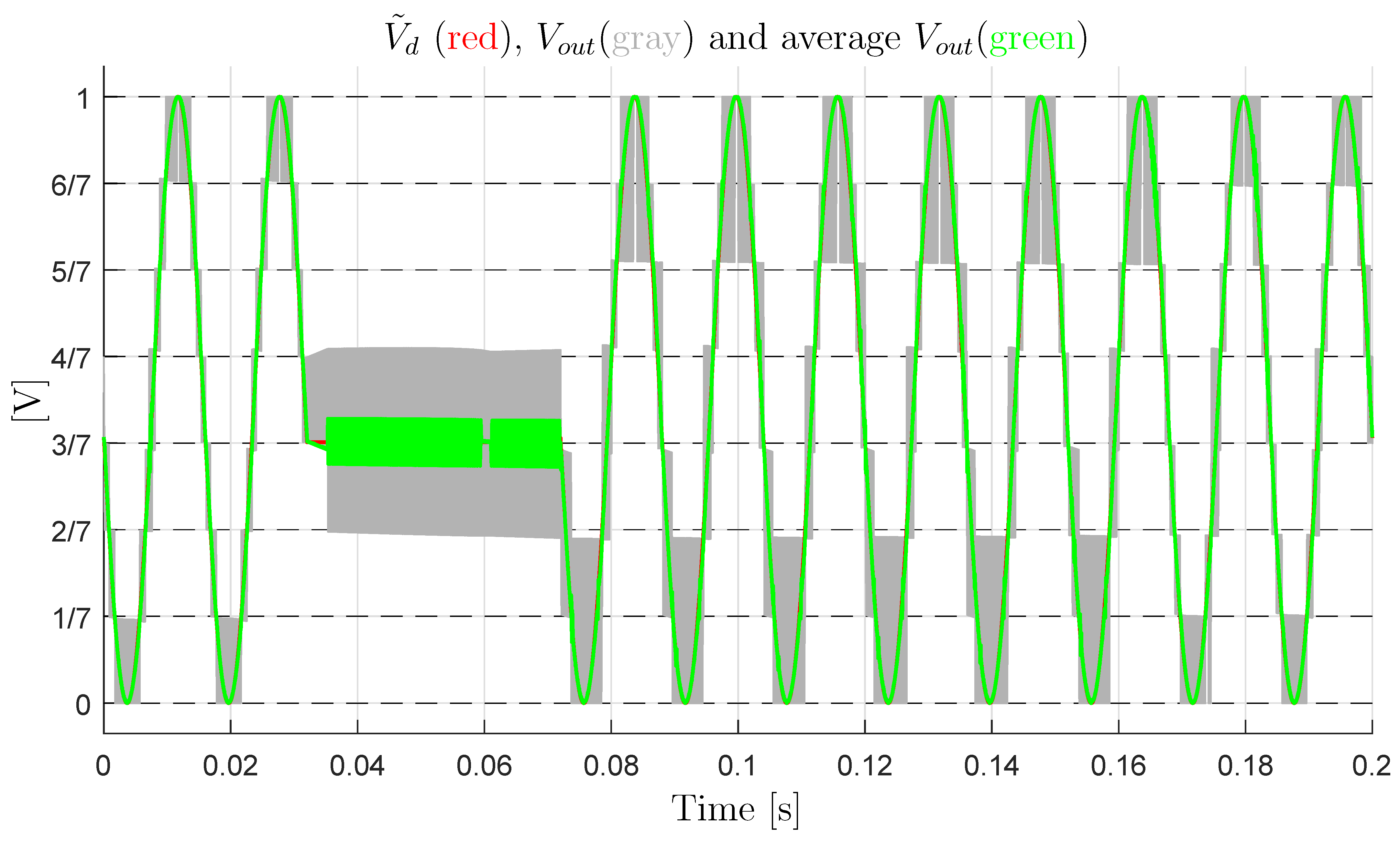
Let us consider the case of a constant output current I o u t = 1.1 A and a sinusoidal desired voltage with an average value that is equal to 0.5: V ˜ d = 0.5 + 0.5 sin ( 393 t ) . Furthermore, the voltage signal is supposed to remain constant at the value V ˜ d = 0.43 for a short time interval t [ t 1 t 2 ] , where t 1 32 ms and t 2 72 ms . Figure 22 shows the simulation results. The red characteristic in Figure 22 is the desired signal V ˜ d , the gray characteristic is the output switching signal V o u t , whereas the blue characteristic is the average value of the output signal V o u t . From the figure, it is evident that: (1) in the first part of the simulation, i.e., t < t 1 , the multilevel converter works correctly, since the output switching levels are equally spaced and, thus, the output voltage error V e r r is very low; (2) during the second part of the simulation, i.e., t [ t 1 t 2 ] , the values of the output switching levels change considerably with respect to the desired ones, and they are no longer equally spaced. Therefore, the average value of the output signal V o u t (blue characteristic) is no longer equal to the desired value V ˜ d (red characteristic); and, (3) in the third part of the simulation, i.e., t > t 2 , the multilevel converter no longer works correctly, since the output signals (the gray and blue characteristics) are no longer equal to the desired one (the red characteristic). This is due to the fact that the trajectories of the reduced voltage vector V ¯ c have diverged from the desired value V ¯ m 0 because of the constant voltage V ˜ d . Moreover, the Minimum Distance algorithm is not able to force the reduced voltage vector V ¯ c to move back towards the desired voltage vector V ¯ m 0 after divergence has occurred.
(B)
Let us consider the case of a sinusoidal desired voltage with an average value that is equal to 0.5: V ˜ d = 0.5 + 0.5 sin ( 393 t ) . The load current is supposed to be constant and equal to I o u t = 1 A for t < t 1 = 0.04 s . Next, a sudden load change causing a current step is supposed to occur, causing I o u t to jump from 1 A to 10.5 A for t 1 t < t 2 = 0.1 s . The load operating condition giving I o u t = 1 A is supposed to be reestablished for t t 2 . Figure 23 shows the simulation results. The characteristics color notation is the same as the one adopted in Figure 22. From Figure 23, it is evident that: (1) in the first part of the simulation, i.e., t < t 1 , the multilevel converter works correctly, since the output switching levels are equally spaced, which means that the output voltage error V e r r is very low; (2) for t [ t 1 t 2 ) , the values of the output switching levels change with respect to the desired ones, and they are no longer equally spaced; and, (3) for t t 2 , the output voltage levels remain unequally spaced, due to the divergence of the trajectories of the reduced voltage vector V ¯ c from the desired value V ¯ m 0 caused by the sudden load change. Moreover, the Minimum Distance algorithm is not able to force the reduced voltage vector V ¯ c to move back towards the desired voltage vector V ¯ m 0 after the divergence has occurred.
Unfortunately, situations such as those that are shown in Figure 22 and Figure 23 can happen for all of the Configuration Voltage Vectors V m , except for the basic one V m * . This poses quite a limitation on the operation of the converter in the so-called “Extended Operation”, namely for V m V m * allowing to generate a number of output voltage levels m > n + 1 for the given n, since unpredictable undesired conditions may compromise the correct functioning of the multilevel converter.

4.4. Variable-Step Control of the Multilevel Flying-Capacitor Converter

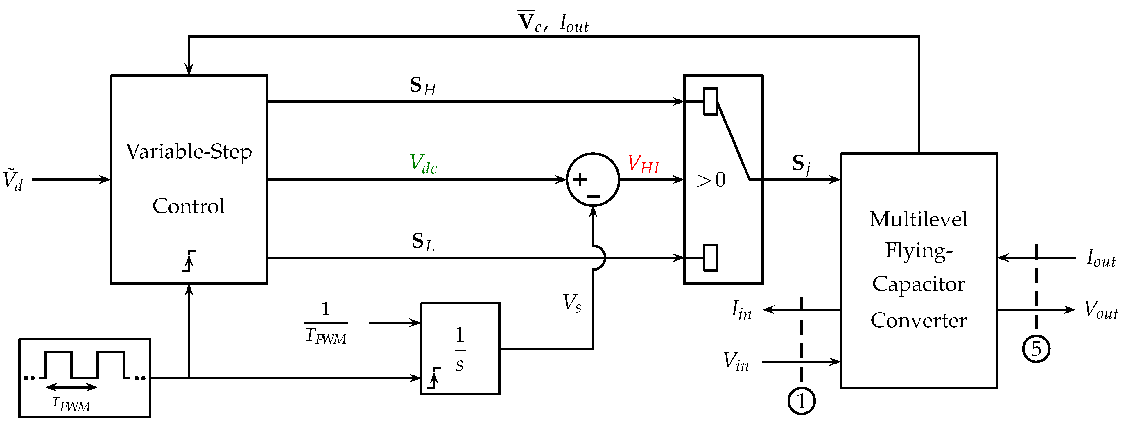
To cope with the divergence problem described in the previous section, the use of a new solution based on the PWM physical scheme that is shown in Figure 24 is proposed.
The basic elements of the new PWM scheme are the following:
(a)
a square wave signal having period T P W M acting as a clock, which activates the Variable-Step Control and resets the integrator to the zero initial condition when the rising edge occurs;
(b)
an integrator with a constant input 1 T P W M and a reset signal that is timed by the square clock. The output V s of the integrator is a sawtooth signal which ranges from 0 to 1 within a time interval t [ t r , t r + T P W M ] , where t r is the reset time instant, see the black line in Figure 25;
(c)
the voltage V d c that is provided by the Variable-Step Control block, defining the duty cycle of the high level of the PWM signal, namely the time interval T H , see the green line in Figure 25;
(d)
the value of the signal V H L = V d c V s determines the output of the selector and, thus, the configuration vector S j , which is going to be applied to the multilevel converter during the next time interval: S j = S H for a time interval T H if   V H L > 0 and S j = S L for a time interval T P W M T H if   V H L < 0 ;
(e)
at each activation time, the Variable-Step Control reads the input signal V ˜ d and generates three output signals: S H , V d c and S L . Using these signals, the Variable-Step Algorithm can decide the duty cycle d c and the two levels S H V c and S L V c of the next PWM period;
(f)
let V H > V d denote the voltage corresponding to configuration vector S H and V L < V d denote the voltage corresponding to configuration vector S L . The duty cycle d c = T H / T P W M of the next PWM period, that is the ratio between the duration T H of the higher level and the duration of the PWM period T P W M , can be computed, as follows:
V d = V H d c + V L ( 1 d c ) d c = V d V L V H V L .
Using (30), the duty cycle d c always guarantees that the average value of the PWM output voltage in the next period T P W M is equal to the desired value V d .
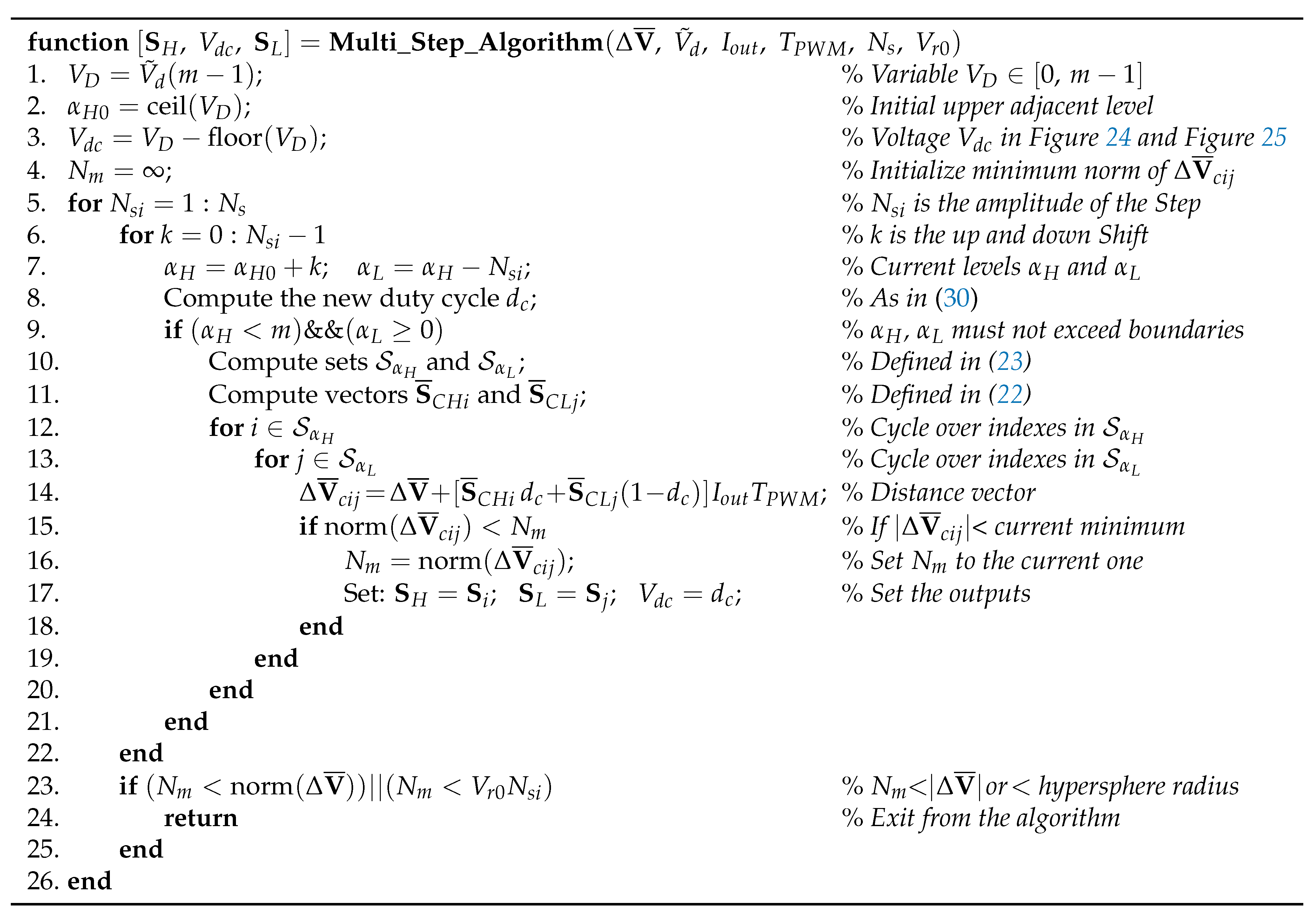
Figure 26 provides the basic structure of the Variable-Step Control algorithm by means of a Matlab-like function called “ Multi _ Step _ Algorithm ( ) ”. This function is called at each activation time providing the following input parameters: Δ V ¯ , V ˜ d , I o u t , T P W M , N s , V r 0 . The “Multi_Step_Algorithm” attempts to keep the reduced voltage vector V ¯ c as close as possible to the desired reduced voltage vector V ¯ m 0 , see (22). The main features of the “Multi_Step_Algorithm” are the following:
  • At each activation time t k , the “Multi_Step_Algorithm” computes the two configuration vectors S H , S L and the duty cycle V d c to be applied in the following PWM time interval [ t k t k + T P W M ] : configuration S H will be applied in the first part of the PWM period when V H L = V d c V s > 0 , while configuration S L will be applied in the second part of the PWM period when V H L < 0 , see Figure 25.
  • The input N s defines the maximum amplitude of the Step to be used in the algorithm, which is the maximum level-to-level distance. The for cycle at line 5 in Figure 26 defines the current value N s i [ 1 , 2 , , N s ] of the amplitude of the Step, i.e., the current level-to-level distance. The for cycle at line 6 defines the current value k of the up and down shift to be considered for the current amplitude N s i of the Step.
  • At lines 7 and 8, the current values of the upper level α H , the lower level α L , and the duty cycle d c are computed. If the current values of α H and α L are admissible, see condition at line 9, then the sets S α H and S α L of the admissible configuration vectors S H i and S L j and the corresponding vectors S ¯ C H i and S ¯ C L j are computed at lines 10 and 11.
  • The two for cycles at lines 12 and 13 are used to compute the distance vector Δ V ¯ c i j for each possible combination of the configuration vectors S i and S j belonging to the two sets S α H and S α L . At line 14, the distance vector Δ V ¯ c i j is computed starting from the initial condition Δ V ¯ and adding the two terms S ¯ C H i d c I o u t T P W M and S ¯ C L j ( 1 d c ) I o u t T P W M , due to the application of the configuration vectors S H i and S L i in the first part d c T P W M and in the second part ( 1 d c ) T P W M of the PWM period T P W M , respectively.
  • If the norm of the distance vector Δ V ¯ c i j is smaller than the current minimum norm N m , see line 15, then the algorithm updates the value of parameter N m , see line 16, and it sets the values of the output variables S H , S L and V d c equal to the values S i , S j and d c of the current solution, see line 17.
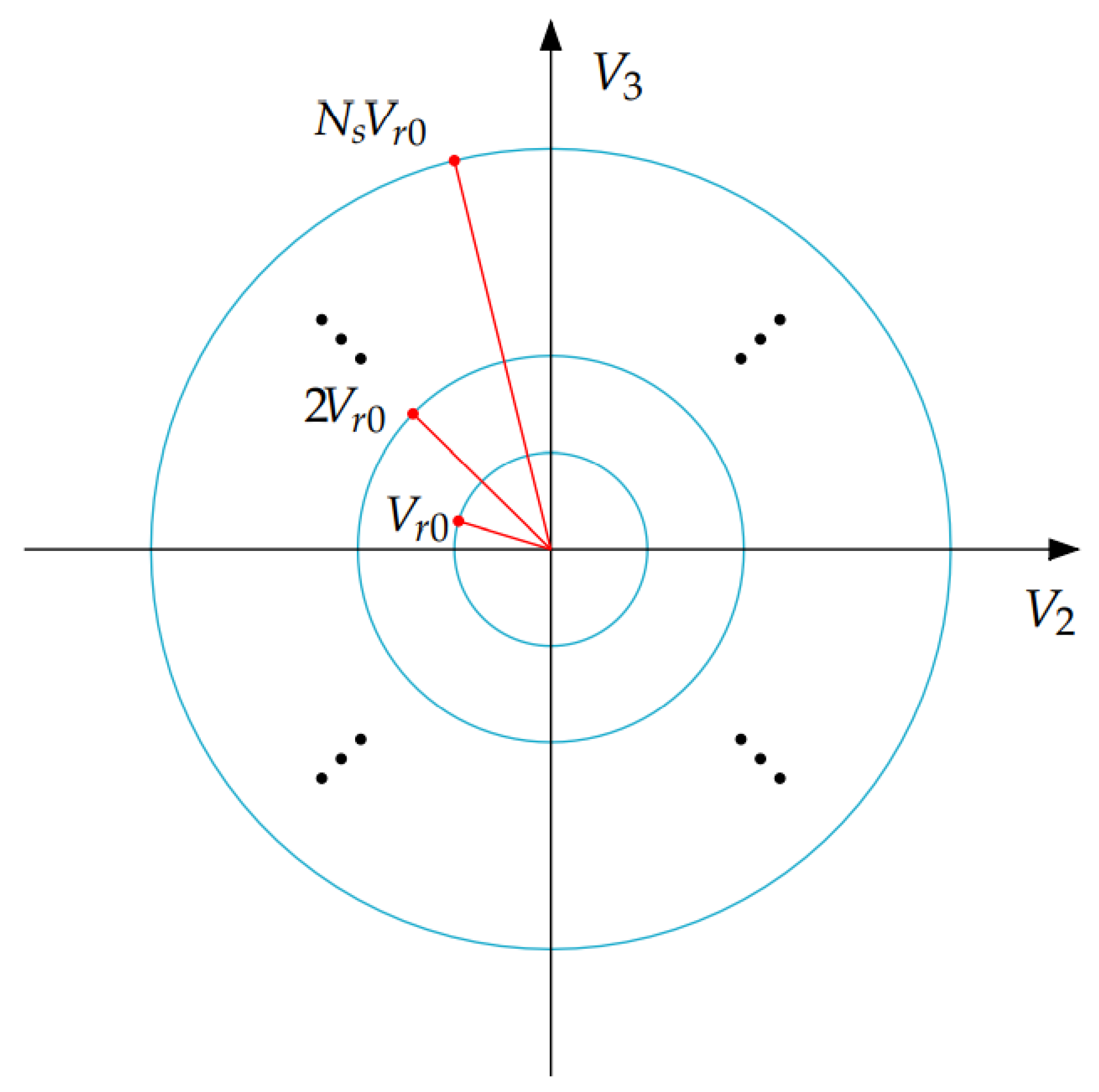
  • The “Multi_Step_Algorithm” ends its minimum distance vector search, see line 24, when one of the conditions at line 23 is verified, or when the maximum level-to-level distance N s has been achieved. At line 23, the algorithm exits the search if the current minimum distance N m is lower than the initial one, or if N m is lower than radius V r 0 N s i , where V r 0 is the input basic radius and N s i is the current level-to-level distance. Radius V r 0 N s i represents the varying radius of an hypersphere in the ( n 1 ) -dimensional space. Figure 27 shows the resulting circumferences with varying radius V r 0 N s i for the case n = 3 .
  • The “Multi_Step_Algorithm” introduces and uses the new concept of “variable level-to-level distance”. This concept means that the algorithm can choose a higher level α H and a lower level α L that are not adjacent, see line 7 of the algorithm. The current level-to-level distance is denoted by variable N s i [ 1 , N s ] . The new duty cycle d c associated with the two levels α H and α L , computed in line 8, guarantees that the average value of the PWM output voltage in the next PWM period T P W M will be equal to the desired value V d .
  • The ability to change the level-to-level distance allows the “Multi_Step_Algorithm” to keep the reduced voltage vector V ¯ c in the vicinity of the desired voltage vector V ¯ m 0 even in extended operation and in presence of some particularly unfavorable operating conditions, such as normalized desired voltage V ˜ d having an average value different from 0.5.
  • If the unfavorable conditions persist, the algorithm can enlarge the level-to-level distance N s i up to its upper boundary N s = m 1 . This enlargement increases the number of the configuration vectors S j that the algorithm can use to keep vector V ¯ c in the vicinity of the desired vector V ¯ m 0 , and to maintain the correct functioning of the multilevel converter. Furthermore, when the unfavorable conditions no longer occur, the “Multi_Step_Algorithm” has the ability to force the converter to go back to work as a normal multilevel converter switching between adjacent levels only, i.e., with a current level-to-level distance N s i equal to one.
  • The example reported in Figure 28 shows all the possible combinations of levels α H and α L that can be obtained when m = 6 , N s i { 1 , 2 , 3 , 4 , 5 } and the desired voltage V D = ( m 1 ) V ˜ d is in between levels “2” and “3”.
Figure 27. Circumference with varying radius N s i V r 0 in the two-dimensional space for the case n = 3 .
Energies 14 01903 g027
Figure 28. Possible combinations of higher and lower output voltage levels α H and α L as a function of the current level-to-level distance N s i for the case m = 6 and a desired voltage V D in between “2” and “3”.
Energies 14 01903 g028

4.4.1. Variable-Step Control: Solution of the Stability Issues in Extended Operation

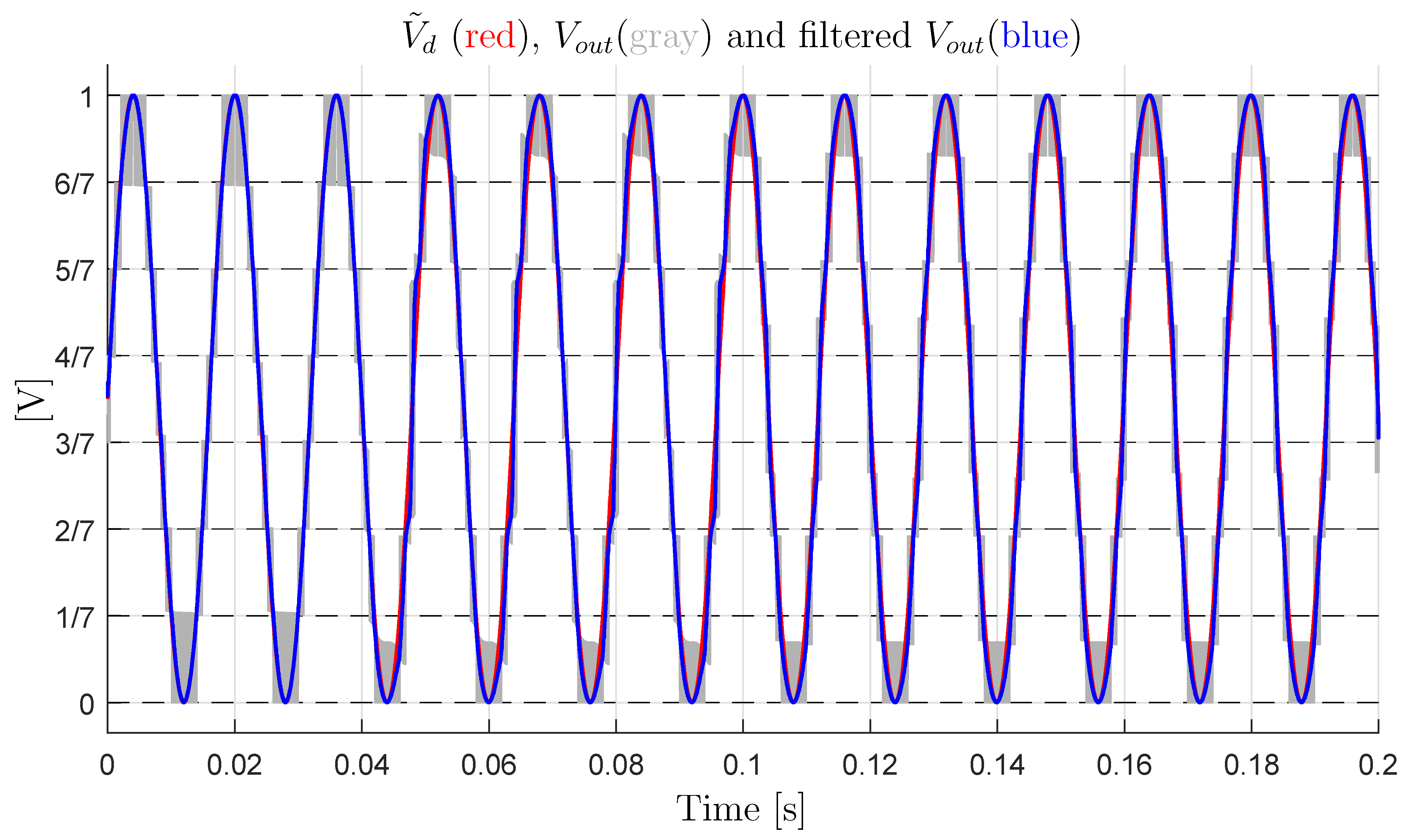
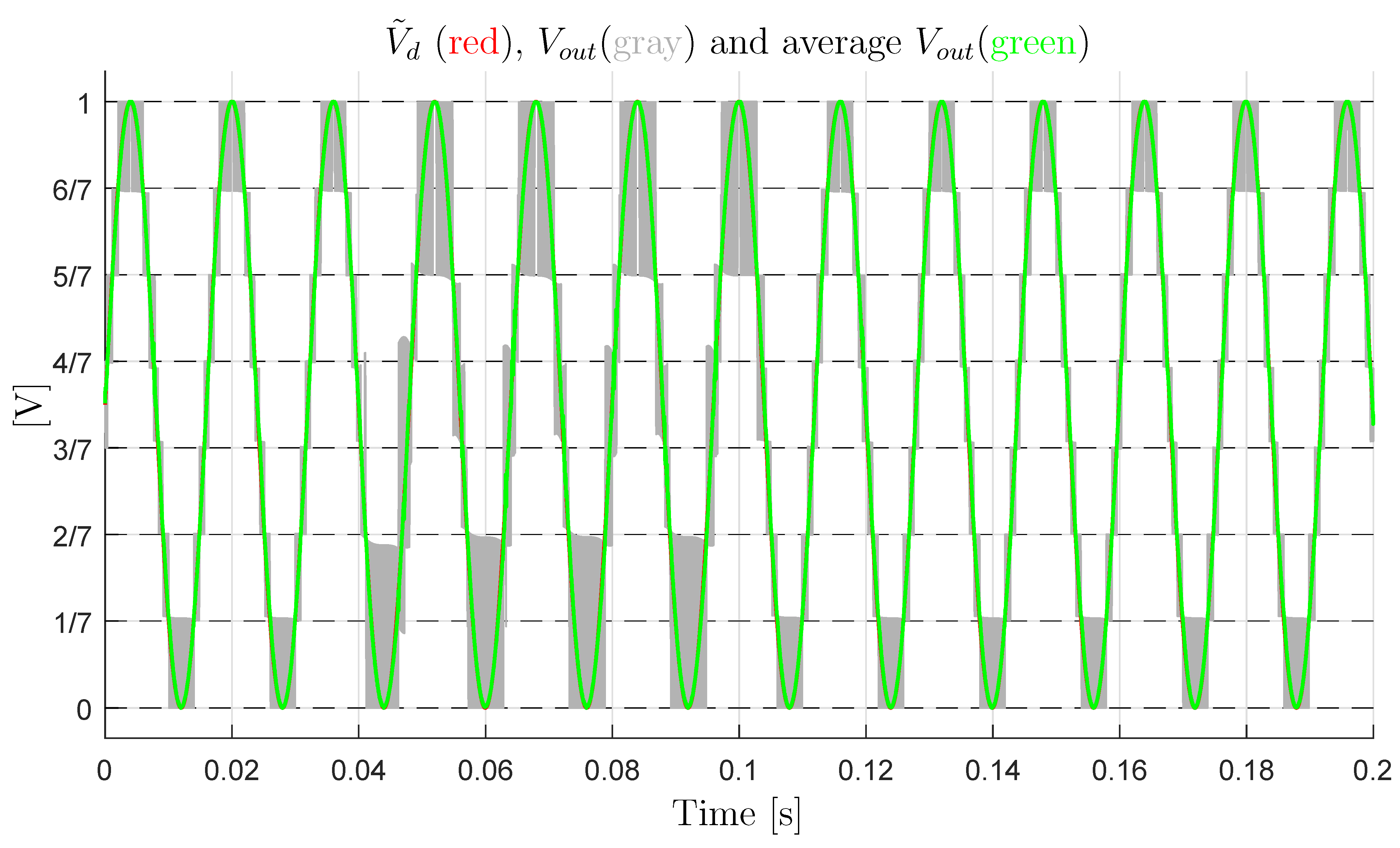
Section 4.3.1 has shown that the Minimum Distance Control is not capable of ensuring the correct operation of the multilevel flying-capacitor converter, in extended mode, under particularly unfavorable operating conditions, such as a desired voltage V ˜ d , with an average value that is different from 0.5 or a sudden load change. Examples of this type are shown in Figure 22 and Figure 23, respectively. On the contrary, the Variable-Step Control that was presented in the previous section is able to ensure the correct functioning of the multilevel converter, even under unfavorable operating conditions. To give some examples, reference is made to Figure 29 and Figure 30, showing the simulation results obtained using the Variable-Step Control under the same operating conditions as those of the simulations in Figure 22 and Figure 23, respectively, when the Minimum Distance Control was used instead. In Figure 29 and Figure 30, the red characteristic is the desired signal V ˜ d , the gray characteristic is the switching output signal V o u t , and the green characteristic is the average value of the output signal V o u t .
With reference to Figure 29, it is evident that: (1) in the first part of the simulation, for t < t 1 , the multilevel converter works correctly in extended operation using the minimum level-to-level distance N s i = 1 and the output voltage error V e r r = V o u t V i n V ˜ d remains low; (2) during the second part of the simulation, for t [ t 1 t 2 ] , the current level-to-level distance N s i increases from 1 to 2, and the gray output variable V o u t switches between levels V L = 2 / 7 and V H = 4 / 7 . In this part of the simulation, the effectiveness of the Variable-Step Control comes into play, which prevents vector V ¯ c from diverging excessively from the desired reduced vector V ¯ m 0 , even in the presence of the unfavorable condition of a signal V ˜ d constant and different from 0.5 . On the other hand, in the simulation of Figure 22, the Minimum Distance Algorithm was not able to prevent the divergence of the vector V ¯ c , therefore compromising the correct functioning of the converter; (3) in the third part of the simulation, for t > t 2 , the operating condition N s i = 2 is maintained until the distance between vectors V ¯ c and V ¯ m 0 is sufficiently reduced, namely until time instant t 3 176 ms ; and, (4) in the fourth part of the simulation, for t > t 3 , the converter starts operating as a classical multilevel flying-capacitor converter in extended mode once again, setting the current level-to-level distance N s i back to 1. On the other hand, in the simulation of Figure 22, the Minimum Distance Algorithm was not able to force the vector V ¯ c to move back towards the desired vector V ¯ m 0 after the divergence occurred.
With reference to Figure 30, it is evident that: (1) in the first part of the simulation, for t < t 1 , the multilevel converter works correctly in extended operation using the minimum level-to-level distance N s i = 1 and the output voltage error V e r r = V o u t V i n V ˜ d remains low; (2) for t [ t 1 t 2 ) , the current level-to-level distance N s i increases from 1 to 2, in order to prevent vector V ¯ c from diverging excessively from the desired reduced vector V ¯ m 0 as a consequence of the undesired sudden load change. On the other hand, in the simulation of Figure 23, the Minimum Distance Algorithm was not able to prevent the divergence of the vector V ¯ c , therefore compromising the correct functioning of the converter; (3) for t t 2 , the operating condition N s i = 2 is maintained until t = t 3 0.1039 s , namely for the very short time interval that it takes for the distance between vectors V ¯ c and V ¯ m 0 to be sufficiently reduced; and, (4) for t t 3 , the converter starts operating as a classical multilevel flying-capacitor converter in extended mode once again, setting the current level-to-level distance N s i back to 1. On the other hand, in the simulation of Figure 23, the Minimum Distance Algorithm was not able to force the vector V ¯ c to move back towards the desired vector V ¯ m 0 after the divergence occurred.
The simulation results that are reported in Figure 29 and Figure 30 clearly highlight the effectiveness of the proposed Variable-Step Control as compared with the classical Minimum Distance Control. This especially holds in those applications, such as the electric motors control, where it can happen that the desired voltage vector V ˜ d does not have an average value equal to 0.5, or that an undesired sudden load change occurs. At the same time, it is desirable to have the converter operating in extended mode, because of all the advantages in the output voltage quality coming from a larger number of output voltage levels without increasing the number of capacitors. The proposed Variable-Step Control aims at enabling the multilevel flying-capacitor converter operation in extended mode any time the operating conditions allow it, and it enlarges the level-to-level distance N s i only when strictly necessary to prevent the divergence of the flying capacitors voltages.
The Reader is invited to refer to the supplementary material in order to test and compare the Minimum Distance Control algorithm and the Variable-Step Control algorithm [28]. The Simulink model “Multilevel_Flying_Capacitor_Converter_mdl.slx” has been created with Matlab R2020b and it contains the dynamic model of the multilevel flying-capacitor converter with n capacitors given in Figure 4, as well as the implementation of both the Minimum Distance Control and the Variable-Step Control. The two algorithms are implemented in the Matlab functions “Distance_Control_0.m” and “Distance_Control_n.m”, respectively. The main script that allows to control the simulations is named “Multilevel_Flying_Capacitor_Converter.m”, where the system parameters that the user can set are reported and commented. Note that variables m and m i i in the script “Multilevel_Flying_Capacitor_Converter.m” denote the number m of output levels and the order m i i of the Configuration Voltage Vector V m , according to the orders that are reported in Figure 20 for the case n = 3 and in Figure 21 for the case n = 4 .

5. Converter Testing with Dynamic Loads

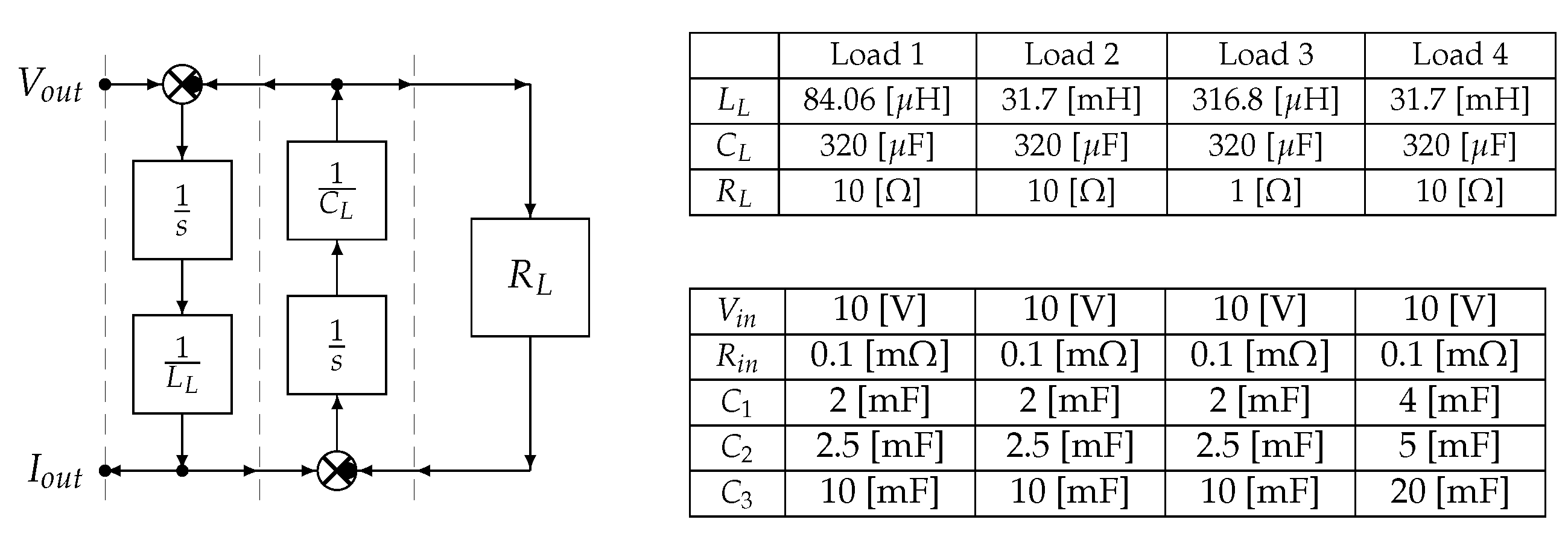
This section deals with the simulation of the multilevel flying-capacitor converter with n = 3 in extended operation, while using the Configuration Voltage Vector V m = [ 5 4 1 ] T , with several proposed load case studies. The considered load configuration is an RLC circuit, where a capacitor C L and a resistor R L are connected in parallel, and their parallel configuration is connected in series to an inductor L L . The described load can be modeled using the POG block scheme that is shown in Figure 31 on the left. The transfer function H ( s ) relating the output power variable I o u t to the input power variable V o u t is the following:
H ( s ) = I o u t ( s ) V o u t ( s ) = s R L C L + 1 s 2 R L C L L L + s L L + R L .
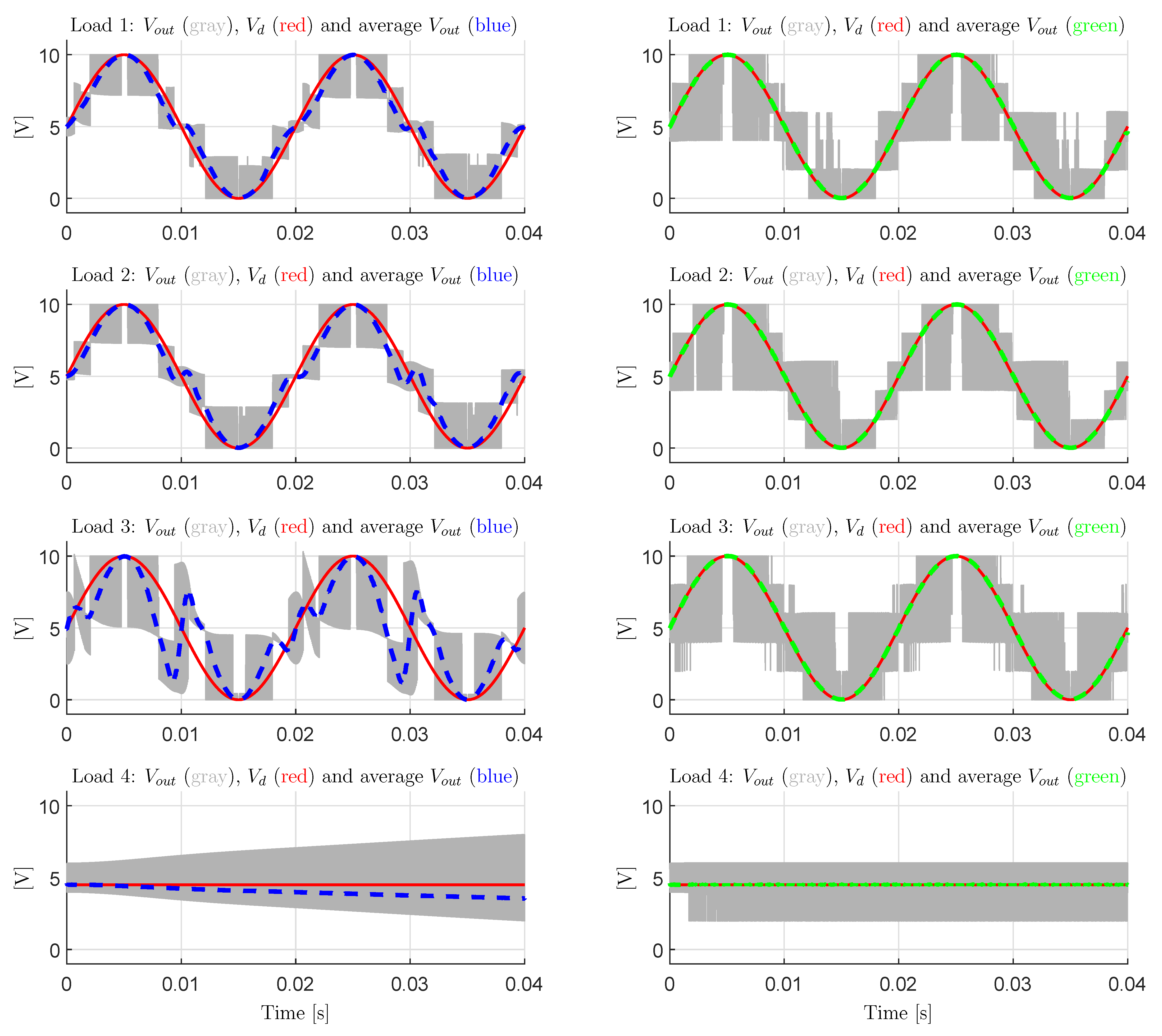
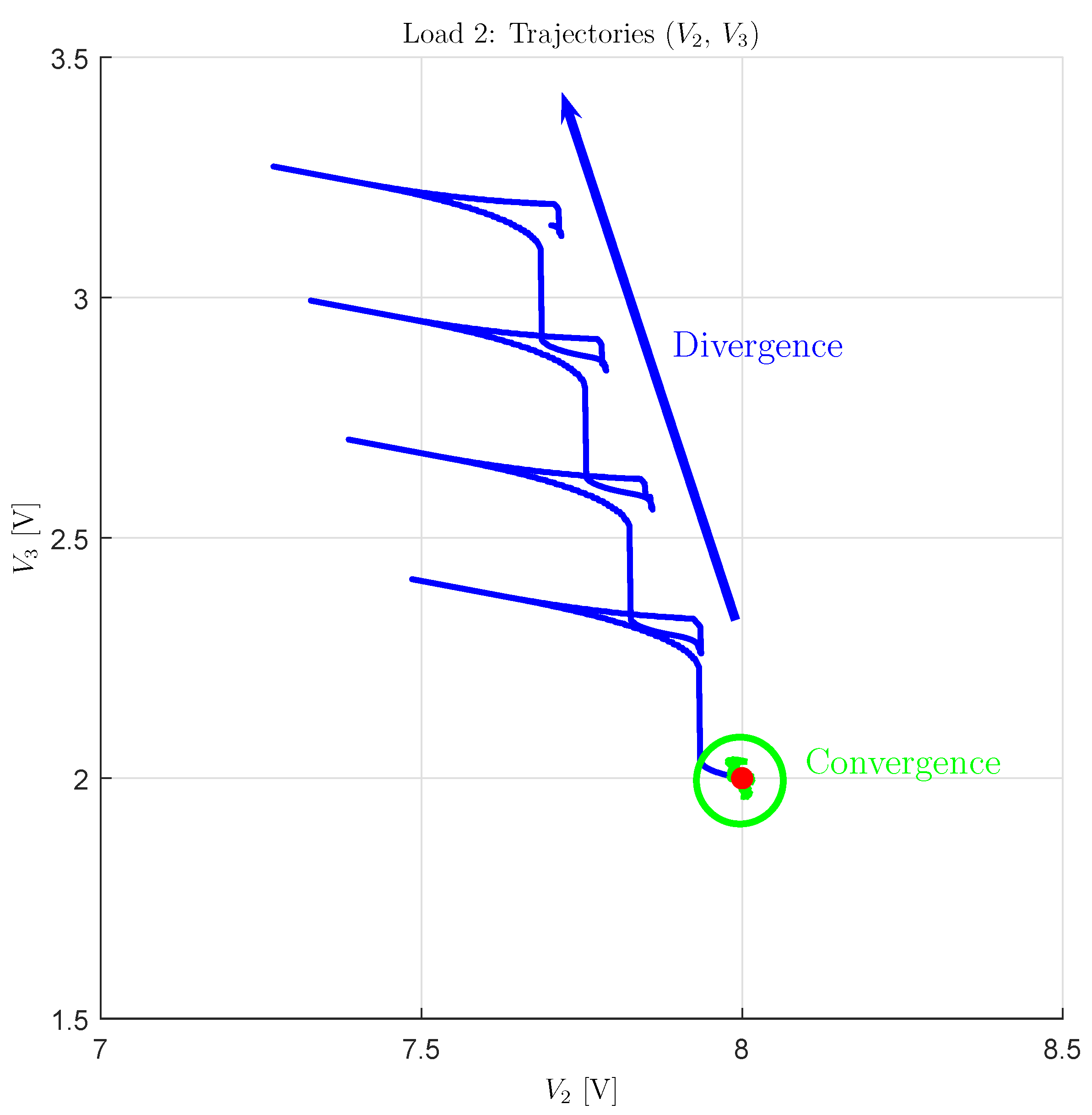
The parameters values for the considered load case studies are shown in Figure 31 on the right, together with the converter parameters. As far as loads 1, 2 and 3 are concerned, the desired voltage V d is assumed to be sinusoidal with an offset that is equal to V i n / 2 , a peak-to-peak amplitude equal to V i n and a frequency equal to 50 Hz . As far as load 4 is concerned, the desired voltage V d is assumed to be constant and equal to 4.5 V. By focusing on the loads 1, 2, and 3, and using the parameters L L , C L , and R L given in Figure 31, one can notice that they represent the cases of voltage V o u t delayed by π / 4 with respect to current I o u t , current I o u t delayed by π / 4 with respect to voltage V o u t , and current I o u t in phase with voltage V o u t , respectively. The initial conditions of the RLC load are assumed to be equal to zero. Figure 32 shows the simulation results in terms of output voltages V o u t . The first three rows of subplots show the simulation results after the transient when the loads 1, 2 and 3 are considered. From the first three rows of subplots on the left-hand side, obtained using the Minimum Distance Control, it is possible to see that the average V o u t characteristic exhibits different degrees of deviation from the desired voltage V d . This is due to the fact that the distance between vectors V ¯ c and V ¯ m 0 tends to increase, even if the average value of V ˜ d is equal to 0.5 , i.e., the average value of V d is equal to V i n / 2 . This can be explained by recalling that the output current I o u t is not constant, as the load is dynamic, which means that the strength of the control action applied by the Configuration Vector S j in (24) changes in time through I o u t , which is a function of V o u t . Without a loss of generality, it is possible to state that this makes the Voltage Configuration Vectors V m different from the basic one V m * loose the full flying capacitors voltage balancing capability, i.e., to become unstable, even when the average value of the desired voltage V d is equal to V i n / 2 . It follows that the distance between vectors V ¯ c and V ¯ m 0 will keep increasing, thus causing the output voltage levels to be increasingly unequally spaced. On the other hand, the subplots on the right-hand side show the very good matching between the average V o u t characteristic and the desired voltage V d when the converter is controlled using the Variable-Step Control. It follows that the Variable-Step Control is capable of handling the cases of non-constant output current I o u t in extended operation as well, by increasing the current level-to-level distance N s i when necessary in order to prevent the divergence of vector V ¯ c from vector V ¯ m 0 . As an example of this, the voltage trajectories of the flying capacitors, namely the components of vector V ¯ c , are shown in Figure 33 for the case “Load 2” when the two different controls are used. From the figure, it is clearly possible to see that the Minimum Distance Control causes the divergence of vector V ¯ c (blue characteristic) from the desired vector V ¯ m 0 , which is highlighted by the red spot in the figure. Furthermore, the blue characteristic also shows that the strength of the control action applied by the Configuration Vector S j in (24) is indeed not constant during the simulation, but it is a function of the output current I o u t , since the length of the blue voltage trajectories in Figure 33 is not constant. On the other hand, the Variable-Step Control is indeed capable of ensuring the convergence of vector V ¯ c to the desired vector V ¯ m 0 .
The fourth row of subplots presented in Figure 32 shows the case of constant desired voltage V d with the load parameters identified by “Load 4” in Figure 31 on the right. The bottom-left subplot shows that the case of constant desired voltage V d V i n / 2 , namely V ˜ d 0.5 , is still the most severe one. This can be seen from the fact that the output voltage levels quickly become unequally spaced because of the divergence of vector V ¯ c from vector V ¯ m 0 . Furthermore, note that the average output voltage in the bottom-left subplot of Figure 32 tends to decrease, as a consequence of the divergence of the vector V ¯ c trajectories. Consequently, the output current I o u t will also tend to decrease. This situation gives rise to an unstable loop: the more V o u t decreases with respect to the desired value V d , the lower the output current I o u t , the weaker the control action applied by the Configuration Vector S j in (24), the more severe the divergence of the V ¯ c trajectories from V ¯ m 0 . However, the bottom-right subplot of Figure 32 shows how the divergence of the V ¯ c trajectories from V ¯ m 0 is prevented by the Variable-Step Control, thanks to the increase of the current level-to-level distance N s i from 1 to 2, showing the effectiveness of the proposed Variable-Step Control.

6. Conclusions

In this paper, the modeling, the control, and the robustness assessment of the multilevel flying-capacitor converter have been addressed. The main contributions of this paper are summarized in the following:
  • the Power-Oriented Graphs modeling technique has been exploited to derive the system dynamic model of the n-dimensional converter, generating a POG model that can be directly implemented in Matlab/Simulink by employing standard Simulink libraries;
  • a procedure for computing all the possible voltage vector configurations V m providing equally spaced levels of the output voltage V o u t has been given;
  • the robustness assessment of the converter operating in extended mode when using a Minimum Distance Control has been performed;
  • a Divergence Index I M has been introduced, which can be used as a metric for properly ordering the different Configuration Voltage Vectors on the basis of their voltage balancing capability in extended operation;
  • a new Variable-Step Control algorithm has been proposed, allowing for the safe extended operation of the converter even under particularly destabilizing operating conditions, such as a constant desired output voltage or a sudden load change.
The good performances of the proposed control algorithm have finally been tested in simulation and compared with the results that are given by the classical Minimum Distance Control.
The next steps of the research work presented in this paper include the code optimization of the Variable-Step Control, in order to study and address its real-time implementation, as well as the investigation of the other potential benefits that the Variable-Step Control can bring. Additionally, the closed-loop stability analysis through the load can provide important criteria that the load must satisfy in order to ensure closed-loop stability. As far as the modeling part is concerned, the presented modeling procedure can be extended in order to show that it can also be easily applied to other converter topologies, such as the diode-clamped topology. Furthermore, we are planning to address the analysis and the modeling of other multilevel converters, in order to perform their stability analysis and investigate the properties they exhibit, following the outlines introduced in this paper for multilevel flying-capacitor converters.

Author Contributions

Data curation, D.T. and R.Z.; Formal analysis, D.T. and R.Z.; Investigation, D.T. and R.Z.; Methodology, D.T. and R.Z.; Software, D.T. and R.Z.; Writing—original draft, D.T. and R.Z.; Writing—review & editing, D.T. and R.Z. All authors have read and agreed to the published version of the manuscript.

Funding

This research received no external funding.

Data Availability Statement

The supplementary material related to this study is available at the link provided in [28].

Conflicts of Interest

The authors declare no conflict of interest.

References

  1. Zanasi, R.; Cuoghi, S. Model of Soft-Switching Converter and Power Control of Grid-Connected Photovoltaic Systems. In Proceedings of the IECON Annual Conference of the IEEE Industrial Electronics Society, Melbourne, VIC, Australia, 7–11 November 2011. [Google Scholar] [CrossRef]
  2. Wu, H.; Mu, T.; Ge, H.; Xing, Y. Full-Range Soft-Switching-Isolated Buck-Boost Converters with Integrated Interleaved Boost Converter and Phase-Shifted Control. IEEE Trans. Power Electron. 2016, 31, 987–999. [Google Scholar] [CrossRef]
  3. Azer, P.; Emadi, A. Generalized State Space Average Model for Multi-Phase Interleaved Buck, Boost and Buck-Boost DC-DC Converters: Transient, Steady-State and Switching Dynamics. IEEE Access 2020, 8, 77735–77745. [Google Scholar] [CrossRef]
  4. Zanasi, R.; Cuoghi, S. Model of Soft-Switching Converter and Power Control for Smart Grid Applications. In Proceedings of the IEEE PES Innovative Smart Grid Technologies, Perth, WA, Australia, 13–16 November 2011. [Google Scholar] [CrossRef]
  5. Al-Badi, A.H.; Ahshan, R.; Hosseinzadeh, N.; Ghorbani, R.; Hossain, E. Survey of Smart Grid Concepts and Technological Demonstrations Worldwide Emphasizing on the Oman Perspective. Appl. Syst. Innov. 2020, 3, 5. [Google Scholar] [CrossRef] [Green Version]
  6. Wu, B.; Narimani, M. High-Power Converters and AC Drives; Wiley-IEEE Press: Hoboken, NJ, USA, 2017. [Google Scholar]
  7. Quraan, M.; Tricoli, P.; D’Arco, S.; Piegari, L. Efficiency Assessment of Modular Multilevel Converters for Battery Electric Vehicles. IEEE Trans. Power Electron. 2017, 35, 2041–2051. [Google Scholar] [CrossRef]
  8. Rodrìguez, J.; Lai, J.-S.; Peng, F.Z. Multilevel Inverters: A Survey of Topologies, Controls, and Applications. IEEE Trans. Ind. Electron. 2002, 49, 724–738. [Google Scholar] [CrossRef] [Green Version]
  9. Rodrìguez Bernet, J.S.; Wu, B.; Pontt, J.O.; Kouro, S. Multilevel Voltage-Source-Converter Topologies for Industrial Medium-Voltage Drives. IEEE Trans. Ind. Electron. 2017, 54, 2930–2945. [Google Scholar] [CrossRef]
  10. Saleh, S.A.; Al-Durra, A.; Ahshan, R. Ground Potentials in Transformerless Grid-Connected Multi-Level Power Electronic Converters. In Proceedings of the 56th Industrial and Commercial Power Systems Technical Conference (I&CPS), Las Vegas, NV, USA, 29 June–28 July 2020. [Google Scholar] [CrossRef]
  11. Saleh, S.; Al-Durra, A.; Ahshan, R. On the Ground Potentials and Grounding Circuits of Transformerless Grid-Connected Multilevel Power Electronic Converters. IEEE Trans. Ind. Appl. 2020, 56, 6286–6297. [Google Scholar] [CrossRef]
  12. Zanasi, R.; Cuoghi, S. Dynamic Models of Multilevel Converters by using the Power Oriented Graph Technique. In Proceedings of the International Symposium on Power Electronics, Electrical Drives, Automation and Motion, Sorrento, Italy, 20–22 June 2012. [Google Scholar] [CrossRef]
  13. Rodrìguez, J.; Franquelo, L.G.; Kouro, S.; Lèon, J.I.; Portillo, R.C.; Prats, M.A.M.; Pèrez, M.A. Multilevel Converters: An Enabling Technology for High-Power Applications. Proc. IEEE 2009, 97, 1786–1817. [Google Scholar] [CrossRef] [Green Version]
  14. Corzine, K.A.; Baker, J.R. Multilevel voltage-source duty-cycle modulation: Analysis and implementation. IEEE Trans. Ind. Electron. 2002, 49, 1009–1016. [Google Scholar] [CrossRef]
  15. Diaz, M.; Cardenas, R.; Ibaceta, E.; Mora, A.; Urrutia, M.; Espinoza, M.; Rojas, F.; Wheeler, P. An Overview of Modelling Techniques and Control Strategies for Modular Multilevel Matrix Converters. Energies 2020, 13, 4678. [Google Scholar] [CrossRef]
  16. Liu, M.; Li, Z.; Yang, X. A Universal Mathematical Model of Modular Multilevel Converter with Half-Bridge. Energies 2020, 13, 4464. [Google Scholar] [CrossRef]
  17. Zanasi, R. The Power-Oriented Graphs Technique: System modeling and basic properties. In Proceedings of the IEEE Vehicle Power and Propulsion Conference (VPPC), Lille, France, 1–3 September 2010. [Google Scholar] [CrossRef]
  18. Zanasi, R.; Geitner, G.H.; Bouscayrol, A.; Lhomme, W. Different energetic techniques for modelling traction drives. In Proceedings of the 9th Internation Conference on Modeling and Simulation of Electric Machines, Converters and Systems (ELECTRIMACS), Québec, QC, Canada, 8–11 June 2008. [Google Scholar]
  19. Zanasi, R. POG Modeler: The Web Power-Oriented Graphs Modeling Program. In Proceedings of the IFAC World Congress, Berlin, Germany, 11–17 July 2020. [Google Scholar]
  20. Brando, G.; Dannier, A.; Spina, I.; Tricoli, P. Integrated BMS-MMC Balancing Technique Highlighted by a Novel Space-Vector Based Approach for BEVs Application. Energies 2017, 10, 1628. [Google Scholar] [CrossRef] [Green Version]
  21. Liao, Y.; You, J.; Yang, J.; Wang, Z.; Jin, L. Disturbance-Observer-Based Model Predictive Control for Battery Energy Storage System Modular Multilevel Converters. Energies 2018, 11, 2285. [Google Scholar] [CrossRef] [Green Version]
  22. Gaisse, P.; Muñoz, J.M.; Villalón, A.; Aliaga, R. Improved Predictive Control for an Asymmetric Multilevel Converter for Photovoltaic Energy. Sustainability 2020, 12, 6204. [Google Scholar] [CrossRef]
  23. Tian, H.; Li, Y.W. Carrier-Based Stair Edge PWM (SEPWM) for Capacitor Balancing in Multilevel Converters With Floating Capacitors. IEEE Trans. Ind. Appl. 2018, 54, 3440–3452. [Google Scholar] [CrossRef]
  24. McGrath, B.P.; Holmes, D.G. Enhanced Voltage Balancing of a Flying Capacitor Multilevel Converter Using Phase Disposition (PD) Modulation. IEEE Trans. Power Electron. 2011, 26, 1933–1942. [Google Scholar] [CrossRef]
  25. Kang, D.-W.; Lee, B.-K.; Jeon, J.-H.; Kim, T.-J.; Hyun, D.-S. A Symmetric Carrier Technique of CRPWM for Voltage Balance Method of Flying-Capacitor Multilevel Inverter. IEEE Trans. Ind. Electron. 2005, 52, 879–888. [Google Scholar] [CrossRef]
  26. Kou, X.; Corzine, K.A.; Familiant, Y.L. Full binary combination schema for floating voltage source multilevel inverters. IEEE Trans. Power Electron. 2002, 17, 891–897. [Google Scholar] [CrossRef]
  27. Huang, J.; Corzine, K.A. Extended operation of flying capacitor multilevel inverters. IEEE Trans. Power Electron. 2006, 21, 140–147. [Google Scholar] [CrossRef]
  28. Link of the Supplementary Material. Available online: http://dii.unimo.it/~zanasi/Personale/Suppl_M.zip.
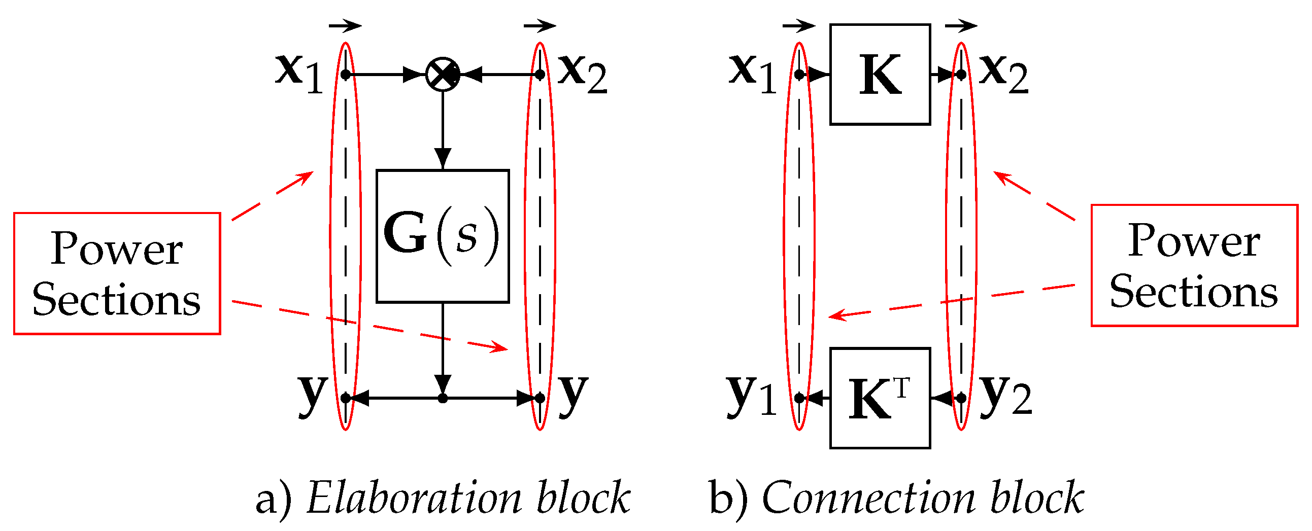
Figure 1. POG elementary blocks: elaboration block and connection block.
Energies 14 01903 g001
Figure 2. Electrical scheme of the n-dimensional Multilevel Flying-Capacitor Converter.
Energies 14 01903 g002
Figure 3. Electrical schemes showing how the output voltage V o u t is obtained as a function of the Insulated Gate Bipolar Transistors (IGBTs) signal vectors T i in the two cases T j = T 2 = [ 0 1 0 ] and T j = T 6 = [ 1 1 0 ] .
Energies 14 01903 g003
Figure 4. Power-Oriented Graphs (POG) model of the Multilevel Flying-Capacitor Converter.
Energies 14 01903 g004
Figure 5. All the Configuration Voltage Vectors V m , in normalized form V ¯ ¯ m , for the case n = 3 .
Energies 14 01903 g005
Figure 6. All of the Configuration Voltage Vectors V m , in normalized form V ¯ ¯ m , for the case n = 4 .
Energies 14 01903 g006
Figure 7. PLECS implementation and parameters of the n = 4 multilevel flying-capacitor converter.
Energies 14 01903 g007
Figure 8. Simulation results given by the PLECS model: output voltage V o u t (upper subplot) and filtered voltage across C L (lower subplot).
Energies 14 01903 g008
Figure 9. Comparison of the results given by PLECS and Matlab/Simulink: output voltage V o u t (upper subplot) and filtered voltage across C L (lower subplot).
Energies 14 01903 g009
Figure 10. Typical scheme of a closed-loop Minimum Distance Control of a Multilevel Flying-Capacitor Converter.
Energies 14 01903 g010
Figure 11. Desired output voltage level α superimposed to normalized desired voltage V ˜ d ( m 1 ) .
Energies 14 01903 g011
Figure 12. Calculations of the Minimum Distance algorithm in the case of n = 3 , m = 4 , V m = [ 3 2 1 ] T when the desired output level is α = 1 .
Energies 14 01903 g012
Figure 13. Stability of the Basic Configuration Voltage Vector V m * = [ 3 2 1 ] T for n = 3 .
Energies 14 01903 g013
Figure 14. Stability of the Basic Configuration Voltage Vector V m * = [ 4 3 2 1 ] T for n = 4 .
Energies 14 01903 g014
Figure 15. Instability of the Configuration Voltage Vector V m = [ 5 4 3 ] T when V d = 0.3 and I o u t = 10 [A].
Energies 14 01903 g015
Figure 16. Instability of the Configuration Voltage Vector V m = [ 5 3 2 ] T when V d = 0.7 and I o u t = 10 [A].
Energies 14 01903 g016
Figure 17. Left subplot: Norm | V m ( V ˜ d ) | of the Vectorial Divergence Function vs. V ˜ d [ 0 , 0.5 ] ; Right subplot: Vectorial Divergence Function V m ( V ˜ d ) on the plane ( V 2 , V 3 ) for all of the Configuration Voltage Vectors V m in the case n = 3 .
Energies 14 01903 g017
Figure 18. Configuration Voltage Vectors V m , for n = 3 , sorted in ascending order with respect to the Divergence Index I M .
Energies 14 01903 g018
Figure 19. Desired voltage signals V d for the comparisons in Figure 20 and Figure 21.
Energies 14 01903 g019
Figure 20. Comparison between the Divergence Index I M and metric max ( Δ V ¯ ) , computed from simulation using three different V ˜ d signals, for the Configuration Voltage Vectors V m in the case n = 3 .
Energies 14 01903 g020
Figure 21. Comparison between the Divergence Index I M and metric max ( Δ V ¯ ) , computed from simulation using three different V ˜ d signals, for the Configuration Voltage Vectors V m in the case n = 4 .
Energies 14 01903 g021
Figure 22. Deformation of the output voltage waveform in the extended operation of the converter with the Configuration Voltage Vector V m = [ 7 6 2 ] T caused by the voltage trajectory divergence in presence of a constant output voltage.
Energies 14 01903 g022
Figure 23. Deformation of the output voltage waveform in the extended operation of the converter with the Configuration Voltage Vector V m = [ 7 6 2 ] T caused by the voltage trajectory divergence in presence of a sudden load change.
Energies 14 01903 g023
Figure 24. PWM physical scheme and Variable-Step Control of the Multilevel Flying-Capacitor Converter.
Energies 14 01903 g024
Figure 25. Scheme for the application of the configuration vectors S j H and S j L associated with the higher and lower level time intervals T H and T P W M T H .
Energies 14 01903 g025
Figure 26. Matlab-like form of the Variable-Step Control algorithm.
Energies 14 01903 g026
Figure 29. Non-Deformation of the output voltage waveform in the extended operation of the converter with the Configuration Voltage Vector V m = [ 7 6 2 ] T , in the presence of a constant output voltage, thanks to the Variable-Step Control.
Energies 14 01903 g029
Figure 30. Non-Deformation of the output voltage waveform in the extended operation of the converter with the Configuration Voltage Vector V m = [ 7 6 2 ] T , in the presence of a sudden load change, thanks to the Variable-Step Control.
Energies 14 01903 g030
Figure 31. On the left: RLC load POG scheme; On the right: RLC load and converter parameters.
Energies 14 01903 g031
Figure 32. Left subplots: simulations using the Minimum Distance Control for V m = [ 5 4 1 ] T ; Right subplot: simulations using the Variable-Step Control for V m = [ 5 4 1 ] T .
Energies 14 01903 g032
Figure 33. Voltage trajectories for the “Load 2” case using the Minimum Distance Control (blue) and the Variable-Step Control (green).
Energies 14 01903 g033
Table 1. Physical elements and power variables in the different energetic domains.
ElectricalMechanical TranslationalMechanical RotationalHydraulic
D e Capacitor CMass MInertia JHydraulic Capacitor C I
v e Voltage VVelocity x ˙ Angular Velocity ω Pressure P
D f Inductor LSpring ERotational Spring EHydraulic Inductor L I
v f Current IForce FTorque τ Volume Flow Rate Q
RResistor RFriction bAngular Friction bHydraulic Resistor R I
Table 2. Relations between the IGBTs signal vectors T j , the output voltage V o u t and the configuration vectors S j when n = 3 .
T j [ T1 T2 T3 ] V o u t [ s1 s2 s3 ] S j V o u t (5) α i
T 0 [ 0 0 0 ] S 0 V c = 0 [ 0 0 0 ] S 0 00
T 1 [ 0 0 0 ] S 1 V c = V 3 [ 0 0 0 ] S 1 V i n / 3 1
T 2 [ 0 1 0 ] S 2 V c = V 2 V 3 [ 0 0 −1 ] S 2 V i n / 3 1
T 3 [ 0 1 1 ] S 3 V c = V 2 [ 0 1 0 ] S 3 2 V i n / 3 2
T 4 [ 1 0 0 ] S 4 V c = V 1 V 2 [ 1 −1 0 ] S 4 V i n / 3 1
T 5 [ 1 0 1 ] S 5 V c = V 1 V 2 + V 3 [ 1 −1 1 ] S 5 2 V i n / 3 2
T 6 [ 1 1 0 ] S 6 V c = V 1 V 3 [ 1 0 −1 ] S 6 2 V i n / 3 2
T 7 [ 1 1 1 ] S 7 V c = V 1 [ 1 0 0 ] S 7 V i n 3
Table 3. All of the Configuration Voltage Vectors V m for the case n = 3 and m { 4 , 5 , , 8 } .
m444555666666777777888888
V m 333444555555666666777777
122233233444334455335656
112112112123121323121244
N β 2343453455674557784568910
Publisher’s Note: MDPI stays neutral with regard to jurisdictional claims in published maps and institutional affiliations.