1. Introduction
The world of automotive engineering has been facing a challenging change that goes far beyond the typical expected evolution caused by technological progress. Global environmental, social, financial and political issues are forcing the powertrain technology of the automobiles’ industry to change its basis: from the Internal Combustion Engine (ICE) to electric motors. This ongoing change, after more than a century of ICE domination in the automotive industry, is provoking an avalanche of modifications and new designs like novel electric Energy Management Systems (EMSs) and regenerative systems capable of electric energy monitoring, distribution, harvesting and storage. Methods, devices like Fuel Cells (FC), batteries, charging devices, DC/DC converters, super-capacitors, hardware and software related to the control of electric motors-generators have become popular research and development objectives, not only at the automotive industry, but also within the scientific community.
The idea of Hybrid power source Electric Vehicles (HEVs) seems to have a great potential in the future of electromobility. The combination of the different characteristics of the alternative power sources utilized at the HEV’s powertrain improves the performance and the efficiency of the whole system [
1,
2]. Several related works are found in the literature. In [
3], a hybrid power system consisting of a 90-kW Proton Exchange Membrane Fuel Cell (PEMFC) and a 600-F Super-Capacitors (SC) bank was developed and installed on an HEV. The efficiency of the system was measured at 96% and the performance and range were adequate not only for an experimental HEV, but also for a typical commercially available passenger car. The control strategy of the electrical power system in this project is based on a set of rules and the control procedure is a sequential algorithm, described by a flow chart. In another related work, the authors propose an EMS installed on a hybrid electric bus [
4]. The system aims at maintaining the state of energy of the SCs’ bank between two limits, which are computed online. The EMS controller follows a set of rules, derived from the state of energy of the SC bank and three other parameters: the maximum speed, the acceleration during propulsion trips and the deceleration during braking trips. The FC and the SC bank are modeled in a simulation environment where real road trip data are used to measure the proposed system’s performance. A different EMS strategy described in [
5], takes into account the FC performance, the DC/DC converters’ characteristics and the SCs’ charging and discharging characteristics to improve the energy consumption, to increase the system’s efficiency and maintain the state of charge of the SCs above a predetermined value. The system is tested and verified on a reduced scale laboratory bench, using an electronic load to simulate the power demand of an EV. The control algorithm is sequential and it is described by a flow chart, representing a set of rules. Marzougui et al. [
6] proposed a two level control strategy for the EMS of an HEV. The equivalent consumption management strategy is at the high level of control whereas at the low level, PI controllers regulate the FC and SC currents, according to the system’s specifications and limitations. This work includes experimental results in simulations. In [
7,
8], novel knowledge-based, multiphysics-constrained and machine learning-based energy management strategies are proposed for hybrid electric buses.
A study of two energy management strategies for HEVs is presented in [
9]. The first is based on a sequential algorithm that follows a set of rules. The second strategy utilizes a sequential algorithm based on a set of fuzzy logic controller rules. Both algorithms are described by flow chart diagrams. The strategies are tested, compared and verified in a simulation environment. In [
10], the authors focus on the comparison of four HEV powertrain configurations along with the analogous EMSs: peaking power source strategy, operating mode control strategy, fuzzy logic control strategy and equivalent consumption minimization strategy. The control algorithms are described by flow chart diagrams, used to represent the set of rules for each strategy. Lawrence et al. [
11] presented an analysis of the systems in a prototype HEV trying to determine if it is possible to increase the vehicle’s efficiency through strategic control of the power provided for auxiliary systems, like the air conditioning or the power steering system. The strategy is based on optimization techniques and it is validated in a simulation environment. The control algorithm is described by a flow chart representing a set of rules. Wu and Gao in [
12] study the minimization of the cost, the volume, the weight and the number of the cells in an FC and the units of an SC bank, combined together to form the powertrain of the HEV. The proposed system is tested using a simulation environment.
Nowadays, the hybrid topology is applied not only to vehicles, tramways and buses but also to ships. Although most of the EMSs in the literature emphasize on other factors than the dynamic characteristics of the respective power generation units of the hybrid system, Tang et al. propose the wavelet method, as a tool to decouple the power demand of a ship into high and low frequency [
13]. After the decoupling, the transient power is designed to be supplied by the SC bank, while the base power is supplied by the FC according to a set of rules. The proposed EMS is tested and verified in a simulation environment.
The popularity of hybrid techniques is presented in detail in the following surveys [
14,
15,
16], which include more than 200 complete works in the scientific field of HEVs, equipped with a combination of hydrogen FC and an energy storage bank of SCs or some kind of rechargeable battery. Many different EMS strategies are presented and tested, including, but not limited to, rule or optimization based strategies, fuzzy logic based control, adaptive neuro-fuzzy inference systems, filtration-frequency decomposition based strategies, optimal control strategies, equivalent consumption minimization strategies, dynamic programming, genetic algorithms, neural network, particle swarm optimization techniques and polynomial control techniques. The authors in [
14,
15,
16] compose an outline of the state of the art EMSs, operating in prototype HEVs, test bench models, commercially available vehicles, pilot projects’ platforms or simulated environments. They present, study, verify and test the variations of architectures and topologies of the electrical hybrid power systems, highlighting their main advantages and disadvantages. They, also, offer access to experimental data, collected from the operation of real vehicles or simulated models.
Regarding the methodology of the EMS control procedure, most of the controller programs found in the literature are sequential algorithms, implementing a set of rules. In certain cases, a flow chart is used for representing the set of rules, which is the base of the control procedure [
3,
5,
9,
10,
11]. The computational model of the Finite State Machine (FSM), may be found in [
17,
18,
19]. In [
17] the authors conduct a comparative analysis on FC based emergency power system of a more-electric aircraft, using simulation and experimental test bench may be found. The analysis refers to the following EMS techniques: the FSM control strategy, the rule-based fuzzy logic strategy, the classical proportional-integral control strategy, the frequency decoupling/fuzzy logic control strategy, and the equivalent consumption minimization strategy. A state machine strategy based on droop control is described in [
18] for a hybrid FC-battery-SC tramway. The proposed EMS strategy is evaluated using real driving data and a hybrid system model of a tramway, made by commercially available devices. In a more recent work [
19] Li et al. introduce a state machine control technique based on the equivalent consumption method for an FC-SC hybrid tramcar. Four states, representing different values of the state of charge of the SC bank, are used at this state machine. The proposed control strategy was tested and evaluated by the RT-LAB semi-physical simulation platform.
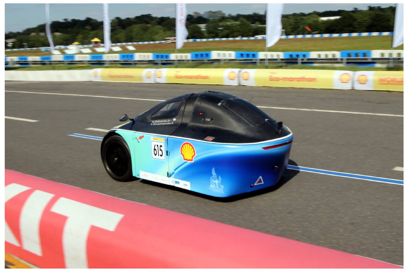
In the proposed work we describe in detail a custom EMS, with unique characteristics, which was developed and installed in Spyros Louis (
Spyridon Louis, commonly known as
Spyros Louis was the Greek Olympic champion of the marathon race at the first Olympic games of modern history, held in Athens in 1896), a racing prototype single-seater car developed and raced by the Technical University of Crete Eco Racing (TUCer) team [
20], in low consumption marathons,
Figure 1. The prototype EMS is based on open source software and low cost off-the-shelf components and devices. Its controller strategy uses an FSM, where the transitions between the states are governed by a set of typical IF-THEN rules. The software framework of the EMS was designed and developed in the Robot Operating System (ROS) environment, which is a meta-operating system developed for robotic oriented applications [
21]. It offers soft real-time control and the ability to organize the controller of the EMS as a straightforward and comprehensive message system that provides the necessary inter-process communication at the core of the EMS control procedure. The program modules were designed and developed, aiming at low complexity, expandability and modularity in an easy to maintain software framework. It is composed of a set of ROS nodes-procedures that are sending, receiving and logging user defined messages, that monitor the sensors’ readings and the controller’s commands. The features of the ROS development environment were exploited for the creation of a soft real-time controller, without the overhead of complicated real-time programming languages and techniques. The aforementioned approach was extensively tested in the laboratory and successfully validated with the participation of the vehicle in the Shell Eco-marathon (SEM) Europe 2019, proven to be safe, efficient and robust.
Based on an extensive literature survey, there is no comprehensive analysis of the software framework or the software programming techniques used to control an EMS. Moreover, to the best of our knowledge, this work is the first implementation of a ROS-based EMS controller. The ROS development environment benefits greatly the successful implementation of the EMS through the adoption of already proven and robust tools for developing a real-time control system, from the robotics domain. We believe that our approach can benefit the research community by proving a methodology for rapid prototyping of not only EMS systems for electric vehicles, but also for expanding the capabilities of their integration and interaction, with other components of an autonomous operation framework which can be supported by ROS, as it has already been demonstrated in a variety of cases [
22]. It is worth noticing that the scope of the paper is not to present an optimized EMS, rather to provide a framework which is
completely independent from the proposed EMS strategy. ROS allows us to easily accommodate, any given approach for developing an EMS and integrate it, in a functional prototype, as it was highlighted by the controller strategy which uses a rule based FSM.
The rest of the paper is organized as follows: in
Section 2, there is a description of the vehicle’s electrical system structure and its basic components. Also, the two modes of the vehicle’s operation, normal and regenerative, are analyzed in terms of energy flow and power switches’ operation.
Section 3 focuses on the ROS-based software implementation of the EMS and presents the FSM model of its controller. Initially we present in detail the ROS nodes and messages’ topics that compose the software framework and describe its interconnections and data formatting. We also give a description of the alphabet, the states and the transitions of the FSM, used at the core of the EMS controller. The evaluation of the proposed approach, using a prototype HEV, is presented in
Section 4. As the proposed system was a part of the vehicle’s powertrain during SEM Europe 2019, this section focuses on the study of data collected from the races. The conclusions from the development of the prototype ROS-based EMS, along with thoughts for further work and future research directions are presented in
Section 5.
2. Electrical System
The overall hardware architecture adopted in this work for the design of the electrical system is presented in
Figure 2. The system is composed of a PEMFC, an SC bank, an isolated buck-boost DC/DC converter, an electric Motor/Generator (M/G), a Motor Driver (MD), an Electronic Control Unit (ECU), three Solid State Relays (SSRs) and three high power diodes (the exact components are listed in
Appendix A).
The electrical system of the HEV has two modes of operation. Each one of these utilizes the components of the electrical system in a different way. In
normal mode operation, the vehicle accelerates or travels with constant speed. The PEMFC and the SC bank are combined together as power sources, to deliver the necessary energy to the M/G. The SSR
1 and SSR
2 are in
ON state, meaning that they allow the electric current to flow through them, while the SSR
3 is in
OFF state. When this mode is active, the M/G consumes energy and acts as an electric motor. The path of the energy flow, for this mode of operation, is presented in
Figure 2 using red lines. A part of the red line route of energy flow is dotted. This is to indicate the bidirectional flow of energy that might occur during normal mode: the PEMFC may, during low consumption periods of the drive cycle, charge the SC bank and, in parallel, drive the electric motor, while in periods of high energy demands both the PEMFC and the SC bank are combined together as power sources to provide the necessary electric energy to the electric motor.
In
regenerative mode operation, the driver stops pushing the acceleration pedal and the vehicle decelerates. The PEMFC is disconnected from the power rail. The SC bank, in turn, is connected to the power rail for charging. This switching task is accomplished by the use of the SSRs. During
regenerative mode operation the SSR
1 and SSR
2 are in
OFF state, while the SSR
3 is in
ON state. Due to the momentum of the vehicle the driving wheel of the HEV keeps on rotating, forces the M/G to rotate and produce electric energy, acting as a generator during this mode. The harvested energy is routed and stored in the SC bank, as shown in
Figure 2 using yellow lines.
A 48 V–1 kW PEMFC stack is used as the primary power source of the Spyros Louis HEV (
Figure 3). It was the preferable option over the alternative available fuel cell types [
23]. A key benefit of this choice, that makes PEMFCs operation relatively more sufficient for vehicles and transportation applications, is the combination of small dimensions with great dynamic characteristics and high energy efficiency [
24].
During the
normal mode operation of the HEV, the PEMFC needs an auxiliary, high power density source to avoid the fuel starvation phenomenon due to the on-the-road dynamic power demand [
25,
26]. The auxiliary power system of the Spyros Louis HEV consists of an SC bank. During steep accelerations the vehicle’s electric motor demands bursts of power. The SC component of the powertrain fulfills these high power density demands in the most effective way, without affecting or harming the reliability and efficiency of the PEMFC operation [
27]. Furthermore, the SC bank is utilized as an energy storage component during
regenerative mode operation. The vehicle’s SC bank consists of 12 modules, configured in 3 parallel components, each composed of four 58 F/16 V modules, connected in series. The total capacitance of the SC bank is 43.5 F at 64 V.
The voltage output of power supply devices like the PEMFCs varies, depending on the current drawn by their load. The voltage of the PEMFC output drops significantly as the load of the MD increases. This behavior decreases the efficiency and the overall performance of the MD. The task that the DC/DC converter performs inside the electrical system, is to maintain a constant voltage value in the DC bus where the MD is connected, regardless the vehicle’s power demands. The input of the DC/DC converter is connected in parallel with both the PEMFC and the SC bank as shown in
Figure 2. The proposed approach is not algorithmic and the contribution of the two different power sources of the DC/DC converter is passive: the fuel cell contributes to the power demands of the DC/DC converter according to its polarization curve while the SCs provide the necessary additional power when the driver asks for high power bursts. Spyros Louis HEV utilizes a 1 kW buck-boost DC/DC converter, with an input voltage range of 19–72 V and an output voltage of 48 V.
During the normal mode operation of the HEV, the DC/DC converter operates as a boost converter. The traction at the Spyros Louis HEV is provided to its rear right wheel, by a three phase brushless 1 kW / 48 V M/G. In regenerative mode operation, the M/G operates as a generator and produces electric energy and voltage values up to 55 V, depending on the HEV’s velocity and the SCs’ state of charge. The M/G is driven by a 12 FET, 36–72 V/40 A MD.
The vehicle’s ECU is a custom made plug in board, that extends the functionality and capabilities of an open source, ARM based, Linux-ROS powered development platform [
28] (the detailed specifications are presented in
Appendix B). Among others, the ECU executes the ROS-based controller program interchanging the FSM states of the EMS, monitors the sensors’ measurements, transmits signals to control the SSRs’ switching activity and manages the flow of energy inside the powertrain of the HEV.
The SSRs actuate the alternative energy paths in the powertrain of the HEV during the
normal or the
regenerative mode of vehicle’s operation. They have high frequency switching capabilities in relatively high voltages values. Also, they offer increased lifetime compared to the typical electromechanical relays, as they have no moving parts to wear out. Three 40 A/200 V SSRs are used in the vehicle’s electrical system. Three 60 A/200 V ultrafast diodes are utilized at the electrical system as a safety precaution. As presented in
Figure 2, the diode
prevents the reverse current from flowing to the PEMFC.
allows current to flow in the MD during
normal mode operation but blocks reverse current from flowing to the DC/DC in
regenerative mode operation.
, blocks any current flow from the SC bank to the MD in
normal mode operation while allows SC bank charging during
regenerative mode operation.
3. Energy Management System Software Implementation
ROS, as already mentioned, provides soft real-time control and communication features by utilizing an
anonymous-asynchronous publish-subscribe mechanism, between the program nodes that constitute the controller. Real time control and inter-process communication is necessary to synchronize the EMS automation procedure. In the typical ROS environment of the proposed EMS, multiple program nodes, running
simultaneously in the ROS multi-thread environment, compose the automation procedure. The timing they provide for actuating the alternative paths of energy flow at the EMS has to be robust, reliable and fully programmable. When this is not the case, severe damages will occur at several devices of the electrical system, destroying the powertrain of the HEV. The challenging and time consuming real-time programming task using multi thread methods, or other techniques, is replaced at the proposed system by the ROS node message-publishing time schedule and the use of timestamps. The ROS timing procedure is transparent to the programmer, that has only to choose the frequency of exchanging data between the program nodes. Thus, the ROS-based source code is reduced in size, easy to comprehend and edit, easy to maintain and debug and significantly more intuitive than the one produced by a typical real-time, multi thread programming language. As it will be described in detail, in
Section 4, ROS soft real-time programming technique proved to be adequate for the time scheduling of the necessary latency periods and the SSRs’ switching activity, for the safe transition between the different modes of the EMS.
ROS programs are organized in program nodes, that are active simultaneously using multitasking techniques. Each one of these nodes may publish data messages in topics and in the same time, act as a subscriber to topics broadcast by some other node. The publishing procedure is time scheduled by the ROS core and fully programmable,
Figure 4. Whenever a subscriber to a topic receives a new message, a control action is triggered. The EMS controller program was divided in discrete parts/nodes for monitoring sensors’ data, logging useful information and routing the controller commands to the actuators of the electrical system of the HEV. Each node is independent from the others and may be in running mode, or not, without affecting the rest nodes. The EMS controller was programmed effortlessly at a high level of abstraction, with the help of the ROS messaging system and the timing tools, offered as a default feature of the ROS environment. The beta source code of the EMS program/nodes was edited, tested and debugged in less than a week and not only is easily maintained but it also may be enriched with new features and functionalities on the fly, by adding the respective nodes.
Inter-process communication is, also, an essential ROS feature, totally transparent to the programmer. ROS ensures that the data flow implementation, in the EMS multi process controller program, is running smoothly. Using library functions from the default ROS messaging system, the necessary data for the control procedure are published in topics by publisher program nodes, with a user defined frequency, when and if they are available. Whenever a message is received by a subscriber program node, a certain control action is triggered. Thus, for example, data collected from a node monitoring the sensors’ readings are published in the respective topic with a user defined frequency. Receiving such a message in a node, subscriber to the same topic, will result to certain control actions, as defined in the subscriber’s node source code. Moreover, the ROS-based EMS controller program is a modular software framework that offers design flexibility, as nodes may be programmed ad hoc and may be added or removed anytime. During the software development or debugging phases, nodes may be activated or terminated, from inside the user space, even during program execution.
Although the ROS-based EMS offers features of high computational cost, like soft real-time control and messaging, still it has reasonable hardware requirements and can be integrated into low power, low cost, open source, terminal based Linux development boards with compact dimensions. These highlighted arguments are crucial for the development of the racing Spyros Louis prototype HEV, with emphasis to low consumption and dimensions. ROS is an open source software that offers a worldwide ecosystem of open source programs and features, organized in the form of software packages, in public repositories. Also, its software package management tools allows the collaboration with the community and facilitates the publication of the EMS controller program in the form of a ROS software package [
29]. More than a year of testing and racing with Spyros Louis HEV, proved that the ROS-based EMS software was reliable, efficient and robust.
The following EMS nodes were programmed using the Python programming language:
data-acquisition node (dN): implements the data acquisition task by accessing and monitoring the sensors. It publishes the collected values to the data-acquisition Topic.
control node (cN): processes data-acquisition Topic message’s data and implements the control procedure. The control node can easily accommodate the integration of any given EMS approach in the ROS framework. In the present work, a hand-tuned rule based FSM was chosen as a proof of concept, to highlight the applicability and functionality of the proposed software frame. The control node publishes some of the control commands as a broadcast to the control Topic and it is a subscriber to the data-acquisition Topic.
logger node (lN): implements the data logging task. It is a subscriber to both data-acquisition Topic and control Topic.
power-off node (pN): implements the system shutdown task. It sends a power-off system call as soon as the HEV’s power switch is turned off.
Two message topics are currently used by the ROS broadcasting system for data publication and subscription among the EMS’s program nodes, the
data-acquisition Topic and the
control Topic,
Figure 5:
data-acquisition Topic (dT): receives messages from the dN and forwards them to both the cN and the lN. The sensors are sampled at a rate of 4 Hz. The messages’ data contain the following measurements:
the velocity of the HEV,
the output voltage and current of the PEMFC,
the voltage of the SC bank and
the current consumed or generated by the HEV’s M/G.
control Topic (cT): receives messages from the cN and forwards them to the lN, with a frequency of 4 Hz. These messages contain the values of two control parameters, the accelerator pedal switch signal and the active FSM state. The accelerator switch signal indicates whether the driver is pressing the accelerator pedal or not, meaning that the HEV is driven in normal or in regenerative mode, respectively.
The
cN is based on an FSM, used as a computational model, consisting of a set of states and transitions. This is a dynamic approach that describes the evolution over time of a set of discrete and continuous state variables [
30]. This technique was chosen because it produces an object-oriented depiction of the system, easily translated to ROS nodes using an object oriented programming language like Python [
31]. Also, the definition of the finite set of states, the alphabet and state transition function is a strict but at the same time straightforward method helping error elimination and debugging. The FSM technique is intuitive and easily conceivable, even for someone with less or none knowledge about the EMS. It is less extensive and complicated than the other representation and programming techniques, like the algorithm or the flow chart. Moreover, it provides the ability of making changes to the EMS by adding or removing states or transitions or both of them. Finally, it is best suited to systems with sequential logic, like the EMS described at this paper.
The FSM, utilized as
cN program node, can be described as the tuple
[
30], where:
FC signal: denotes a confirmation signal received from the PEMFC. The signal declares an error-free, stand-by condition of the PEMFC.
accelerator pedal switch: indicates whether the driver is currently pressing down the accelerator pedal,
velocity: indicates the instant velocity value of the HEV and
velocity threshold: indicates a velocity value. Below this value there is no regenerative electric energy harvesting during the regeneration mode operation. Namely, the M/G will not produce any electric energy, acting as generator, if the HEV is moving at a velocity with lower value than the velocity threshold.
The EMS operation is composed by six states, presented at
Table 1 and described below. The transition time between different states is 0.25 s and follows the publishing frequency of the sensors’ data published at the data-acquisition Topic (dT).
Initialization state: the initial FSM state, , represents the system start up state. The ECU initializes its control outputs and awaits for the FC signal. The FC signal is a confirmation signal produced by the PEMFC to declare its error-free, stand-by condition. All the SSRs are at the OFF state.
Idle: after receiving the FC signal from the PEMFC, denoting its normal stand-by condition, the FSM is shifted to the idle state . At this state, the HEV is motionless, or it is moving with a velocity less than the velocity threshold. The SSR1 and the SSR2 are ON, to permit the power flow to the DC/DC converter, while the SSR3 is OFF since there is no regenerative energy flow.
Normal mode operation: the moment the driver presses the accelerator pedal and the accelerator pedal switch is turned on, the FSM transitions to , that represents the normal mode operation of the HEV. Taking into consideration the throttle signal, different volumes of acceleration are being instructed to the MD. The state of the SSRs is the same as in the state.
Intermediate step from normal to regeneration mode: when the driver wants to decelerate the vehicle and releases the accelerator pedal, the accelerator pedal switch is turned off and the FSM progresses to . This state is an intermediate fail-safe state, ensuring that enough time is given to the SSRs to be set properly, before entering the regeneration mode operation. All the SSRs are OFF.
Regeneration mode operation: if the
accelerator pedal switch remains turned off, the FSM is shifted from
to
state, that corresponds to the
regeneration mode operation. There are two alternatives for exiting from
. According to the first, the exit may happen if the velocity value decreases below the
velocity threshold. In this case the FSM will move back to the
idle state. According to the second alternative, the exit from
may happen if the driver presses the accelerator pedal that turns the
accelerator pedal switch on. At this case, the FSM transitions to
. The SSR
1 and the SSR
2 are OFF, while the SSR
3 is ON to utilize the alternative energy flow during the regenerative mode, indicated by the yellow line at
Figure 2.
Intermediate step from regenerative to normal mode: is another intermediate fail-safe state, ensuring that enough time is given to the SSRs to be set properly before the FSM exits the regenerative and enters the normal mode operation. All the SSRs are OFF.
4. System’s Evaluation
The proposed ROS-based EMS system was thoroughly tested on the prototype HEVs and the prototype chassis dynamometer [
32] of the TUCer team. The prototype urban concept racing HEV Spyros Louis, equipped with the proposed EMS, took part at the SEM Europe 2019 (
Figure 1). To successfully complete the race, the vehicle had to complete 11 laps in a closed track,
Figure 6, in no more than 39 min. Each time that the vehicle was completing a lap, it had to perform a
stop-and-go procedure of 5 s. The length of the track was 1420 m. The EMS operated faultlessly and proved its reliability and robustness. Moreover, the fine tuning process during the trial laps and between the races was straightforward, thanks to the modular design of the ROS-based controller and the deployment of the FSM. The
Figure 7,
Figure 8,
Figure 9,
Figure 10,
Figure 11 and
Figure 12 are diagrams presenting the values of the most important EMS parameters. These values were collected using data logged during the three first laps of the first race of the SEM Europe 2019.
Figure 7 depicts the velocity values of the HEV, along with the states’ transitions during the 215 s period of the first race lap. The HEV accelerates until the 140th second. The FSM state is shifted from the
state to
at the first second, as the vehicle starts to operate at
normal mode and remains unchanged until the 140th second. At the period from the 140th second to the end of lap there are successional transitions of the EMS operation between normal and regenerative mode. At this part of the lap there were successive turns on the race track, where the vehicle was successively accelerated and decelerated, before and after the turn respectively. The states’ transitions follow the variations of the velocity profile. Thus, for example, during the first deceleration phase, starting at the 140th second, the FSM is shifted from the
state to the intermediate
and from there instantly to the
state, where it remains for a couple of seconds until the driver accelerates again. At this acceleration phase the FSM is shifted from
to the intermediate fail safe
and instantly back to
, where it remains during the rest of the normal mode operation. For the last 5 s of the lap, the vehicle is standstill due to the stop-and-go procedure, and the FSM state finally changes to
, as soon as the velocity value of the vehicle decreases below the velocity threshold.
Figure 8 depicts the motor power along with the SC voltage values’ variations during the 215 s of the first race lap. As the HEV accelerates until the 140th second the electric power consumed by the motor varies between 75 W and 1080 W approximately. At the same period the voltage value of the SC bank is reducing, almost continuously, as electric energy flows from the bank to the motor and the HEV’s PEMFC cannot sufficiently compensate the accelerations’ energy bursts. The SC bank voltage looses more than 12 V at this phase of normal mode operation. After the 140th second, during the successional transitions of the EMS operation between normal and regenerative mode due to the race track turns, the motor power turns to zero whenever the HEV decelerates. This happens, for example at the period from the 144th to the 149th second. At the same period there is a sudden increase st the SC bank voltage value, due to the electric energy harvesting during the regenerative mode operation. This procedure of successive transitions between acceleration and deceleration of the HEV is repeated for five times in total, after the 140th second and until the end of the lap. At the last 5 seconds a stop-and-go interval takes place and the FC is charging the SC bank, while the motor power consumption is zero as the vehicle is standstill.
Figure 9 depicts the velocity values of the HEV, along with the states’ transitions during the 200 s that lasted the second race lap. This lap is slightly quicker than the first one. The HEV accelerates until the 53th second, when it starts to decelerate before the first wide turn of the track, due to its higher, than in the first lap, velocity. At the start of the lap the FSM state is
and immediately shifts to
as the vehicle starts moving. The next state transition will occur at the 53th second when the vehicle decelerates and a regenerative mode operation begins with a successive transition from the
state to the intermediate
, to
and to the intermediate
. From the 60th until the 75th second and from the 87th until the 125th second of the lap the vehicle also accelerates. The FSM state is
for the whole period from the 53th to 125th second, although there is a brief interval of deceleration between 76th and 85th second. At this interval, there is no transition to a regenerative mode operation because the driver keeps on pressing the acceleration pedal, though less than before and thus the vehicle decelerates. After the 125th second and until the end of the lap, the successional transitions of the EMS operation between normal and regenerative mode are repeated the same way, as at the end of the first lap. After the 195th second, when the velocity value of the vehicle decreases below the velocity threshold, the FSM state changes to
. The FSM remains at the
state until the end of the second lap as a stop-and-go procedure follows at the last 5 seconds and the vehicle is at a standstill.
Figure 10 presents the motor power along with the SC variations of the voltage values, during the 200 s of the second race lap. From the start, until the 125th second the electric power values vary between 0 and 1100 W approximately. In general the power values are higher than the ones of the first lap, due to the higher velocity values of the second lap. At the same period, the voltage value of the SC bank is continuously reducing, apart from the periods of vehicle deceleration, as for example from the 74th until the 88th second, where the motor power consumption is reducing and thus the FC has the opportunity to charge the SC bank. A phase of successional transitions between normal and regenerative mode operation follows, due to the race track turns. At this phase, the motor power falls to zero whenever the HEV decelerates, as for example at the period from the 135th to the 144th second. At the same period the SC bank voltage value increases, due to the electric energy harvesting during the regenerative mode operation. At the end of the second lap, at the stop-and-go interval of 5 s, the SC bank voltage value increases as the SCs are charging.
Figure 11 and
Figure 12 describe the third lap of the race, that is completed in 210 s. The velocity values of the HEV are increasing after the start of the lap, as it accelerates until the 135th second, apart form a deceleration interval from the 48th to the 58th second. At the start, the FSM state is shifted from the
state to
, as the vehicle operates at
normal mode. The state does not change until the 135th second, apart from the interval from the 48th to the 58th second where a
regenerative mode phase shifts the FSM state from
to
, to
and
. From the 135th second until 5 s to the end of the lap there are four successional transitions from
normal to
regenerative mode operation where the velocity values are increasing and decreasing respectively. At this period, the transition from the
state to
, to
and
, due to the activation and deactivation of a
regenerative mode operation is repeated four times. After the 210th second, the velocity value of the vehicle decreases below the
velocity threshold and the FSM state changes to
, and remains so until the end of the lap.
As shown in
Figure 12, the electric power consumed by the motor varies between 0 and 1100 W approximately until the 122th second. The zero values correspond to a
regenerative mode phase from the 48th to the 58th second. At the same period, from the start until the 122th second, the voltage value of the SC bank is reducing, apart from the deceleration phase of the vehicle, from the 27th to the 58th second, where the value increases due to the low power consumption and the
regenerative mode phase. After the 122th second, there are four successional transitions of the EMS operation between
normal and
regenerative mode, the motor power turns to zero whenever the HEV decelerates and the SC bank voltage value increases and decreases respectively. This happens, for example at the period from the 165th to the 172th second. At the last 5 s of the lap the motor power is zero and the SC bank voltage increases, as the vehicle is standstill due a stop-and-go interval.


 ,
, 