Article

An Intensification of Biomass and Waste Char Gasification in a Gasifier

by
Rolandas Paulauskas
*,
Kęstutis Zakarauskas
and
Nerijus Striūgas
Laboratory of Combustion Processes, Lithuanian Energy Institute, Breslaujos Str. 3, LT-44403 Kaunas, Lithuania
*
Author to whom correspondence should be addressed.
Energies 2021, 14(7), 1983; https://doi.org/10.3390/en14071983
Submission received: 19 February 2021 / Revised: 24 March 2021 / Accepted: 26 March 2021 / Published: 2 April 2021

Abstract

:
Gasification is considered a clean and effective way to convert low quality biomass to higher value gas and solve various waste utilization problems as well. However, only 80% of biomass is converted through thermal processes. The remaining part is char, which requires more time for conversion and in that case reduces the efficiency of gasifier. Seeking to optimize the process of gasification, this work focuses on the intensification of residual char gasification in a gasifier. For this purpose, three different types of char prepared from wood, sewage sludge and tire were examined under different conditions in a lab-scale gasification setup. Results showed that the air flux increase from 0.11 kg/(m2s) to 0.32 kg/(m2s) intensified the gasification process and the gasification rate increased from 0.8 to 2.61 g/min with the decrease of duration of wood char gasification by 72%. An additional introduction of pyrolysis gas into the char gasifier led to decreased bed temperatures, but the gasification rate increased from 0.8 to 1.25 g/min and from 2.61 g/min to 2.83 g/min, respectively, for the wood char and the sewage sludge char. Moreover, the use of pyrolysis gas coupled with air as the gasifying agent enhanced the composition of produced gas from char, and the CO2 concentration decreased by 1.68 vol% while the H2 concentration increased by 2.8 vol%.

1. Introduction

Gasification is considered a clean and effective way to convert low quality biomass to higher value gas and solve various waste utilization problems as well. For example, low-quality wood, agricultural biomass, sewage sludge, timber waste, or bio-waste could be converted to syngas consisting of CO, H2, CO2, CH4, N2 and other components at the concentrations up to 0.2 vol% and consumed for heat and power production [1,2,3]. On the other hand, the obtained products are suitable for further conversion to bio-methane [4,5], hydrogen [6,7], or Fischer–Tropsch (F–T) synthesis [8]. However, the yield of the final product depends on the syngas composition, which in turn is closely related to the used feedstock, gasifying agent, temperature and gasifier design. Currently, there are proposed many designs for gasifiers such as fixed bed (updraft or downdraft), moving bed, bubbling fluidized bed and circulating fluidized bed [9]. Among these, fixed or moving bed gasifiers are the most common for investigation of new feedstock or configuration and besides have a wide applicability, sizing and range of thermal power [10]. Meanwhile, the fluidized bed gasifiers like bubbling fluidized bed (BFB) and circulating fluidized bed (CFB) are well known for a stable temperature and operation, wide range of fuel, but basically are developed in a large scale [11,12]. Despite the differences of these systems, normally only up to 80% of biomass is converted into volatile matter through thermal processes [13,14]. The residual part is condensable tars and solid char, which requires several tens of times more for full conversion than the release of volatile substances from solid biomass as the oxidant hardly diffuses into the formed biochar [15]. The char conversion rate also depends on the feedstock type and gasification temperature. According to the previous work [16], the gasification of wood chips at 1100 °C led to amount of char of 4.8 wt.%, but using pelletized fuel (straw, poultry litter, sewage sludge) the gasification temperature was between 800–850 °C to avoid bed agglomeration and the amount of remaining char was higher and varied between 7.8 wt.% and 14.3 wt.%. Additionally, the remaining char reduces the efficiency of gasifier as the char consists of 30–90 wt.% of carbon.
The gasification-derived char has gained a lot of attention due to its wide applicability [17]. Considering energy applications, the char use for the tar reforming of pyrolysis gas or syngas or char gasification has shown promising results. Palla Assima et al. [18] used residual char pellets and ash from a gasification setup. The results revealed that the tar content was reduced from 65 g/m3 to 90.2 mg/m3. A different setup was presented by Zhang et al. [19], which coupled the pyrolysis and catalytic reactor. In that way, the produced wood char via pyrolysis was used in the catalytic reactor for a hot gas filtration, which reduced the tar content below 100 mg/m3. Another work [20] describes a two-stage gasification setup, which separates pyrolysis and char gasification stages. Biomass is first dried and devolatilized in the first stage. Next, the formed char falls to the second stage, where it is gasified by steam and CO2. However, results showed that the system was not flexible for different type of biomass and was most suitable for wood chips. A different method of residual char usage was proposed by Van de Steene et al. [21], which focused on wood char gasification in a continuous downdraft fixed bed reactor. The experiments using the wood char were performed in a specially developed CFiB reactor. It was determined that the char gasification took in the first 10 cm of the bed and 81% of carbon was consumed if steam gasification was applied. Due to steam addition, the water-gas-shift reaction took place and hydrogen concentration increased by 22%. In another work [22], the authors compared the gasification of char from wood and wood pellets. Results showed that there were no differences between pellets and chips on syngas quality and char conversion. However, the reactive zone of the char bed was three times wider for chips compared to pellets. Authors assumed that char pellets required less height of gasifier to fully convert the residual char.
According to reviewed literature, char gasification is mainly performed in the two-stage gasifier or even in a separate one. Though, another option related to thermal conversion of char is to intensify the char gasification in the remaining gasifier, in which case the gasifier efficiency increases, remaining energy from unconverted char is recovered and syngas composition is enhanced. However, studies related to this option are lacking, and in order to implement this method, the knowledge on conditions like the gasifying agent amount and type, the bed temperature distribution, produced gas composition, fuel equivalence ratio, etc. is required. To acquire required knowledge, a char gasification unit was designed based on the reduction zone in the downdraft gasifier setup and three different types of char prepared from wood, sewage sludge and tire were examined supplying different air flux of air. In addition, to investigate syngas effect on char gasification and enhancement on syngas composition, the pyrolysis gas was produced on site and supplied to the char gasification unit.

2. Materials and Methods

2.1. Used Materials

Experiments based on intensification of residual char gasification were performed using three different types of char: wood, sewage sludge and tires char. The type of char was selected based on the purpose to compare common fuel (wood) char gasification with ones causing gasification problems (sewage sludge, tires). These chars were collected after feedstock gasification in a downdraft gasifier (Figure 1), which is described in previous works [16]. The main parameters of used char are presented in Table 1.

2.2. Experimental Setup and Procedure

Experiments were performed in a lab-scale char gasification unit consisting of an electrically heated furnace 1 and a closed stainless-steel tube 2 (1000 mm length, 37 mm i.d.) (see Figure 1). The tube was mounted inside the furnace. In order to measure a temperature distribution per reactor height during the gasification process, 6 K-type thermocouples (accuracy ±0.75%) were installed inside the tube. Thermocouples were arranged in different locations: T1 at the bottom of the bed (0 mm), T2 at 0.075 m from the bottom, T3 at 0.12 m, T4 at 0.245 m, T5 at 0.375 m and T6 at 0.50 m. Readings of these thermocouples were collected using a data logger TC-08 (Pico) and transferred to PC. Differential pressure in the bed was measured as well. At the exit of the gasification reactor, a three-way valve was installed to direct a part of gasification products for the gas and the tar analysis and the rest part to a vent. A composition of gaseous products from the gasification reactor was determined by a gas analyzer VISIT 03H.
Before starting the gasification experiments, the prepared char was loaded to the tube (180 ± 3 g of char) and the gasification reactor was heated electrically up to 800 °C temperature. The heating up to desired temperature guaranteed the self-gasification of char upon an introduction of the gasifying agent. At the same moment as the gasifying agent was supplied, the electrical heating of the gasification reactor was turned off. The char gasification experiments were performed in two ways using different gasification agents: (A) air and (B) pyrolysis gases + air (see Figure 1).
In the first case, the air was supplied from a compressed air reservoir and a flow of air was precisely controlled by a mass flow controller (Brooks, 0.2% full scale). The char gasification experiments were performed by maintaining different air fluxes, from 0.11 to 0.32 kg/(m2s), and the temperature profile of char reactor and composition of producer gas from char were determined. The air flux was calculated by the following equation:
D = V A ,
where V—air flow rate to reactor (kg/s), A—grate area m2.
In the second case, pyrolysis gases were obtained in the following way: nitrogen (99.6% purity AB “Achema”) was supplied to a container with fuel pellets at constant pressure and flow of 1.8 L/min. A screw conveyer maintained a constant quantity of fuel pellets (5 g/min) from the container to the pyrolysis reactor. Commercially available wood pellets made from softwood, mainly spruce and pine (UAB “Baltwood”), were used for the production of pyrolysis gases. The composition of pyrolysis gas is presented in Table 2. A constant temperature of 850 °C was maintained in the pyrolysis reactor and the produced pyrolysis gas was supplied to the bottom of the reactor (see Figure 1B). During experiments, a constant gas flow of 6 L/min was maintained to ensure comparability of results. In both cases, gasification conditions were maintained until the CO and CO2 concentrations at the exit were below the detection limit.

3. Results and Discussion

3.1. Analysis of Char Gasification under Air Conditions

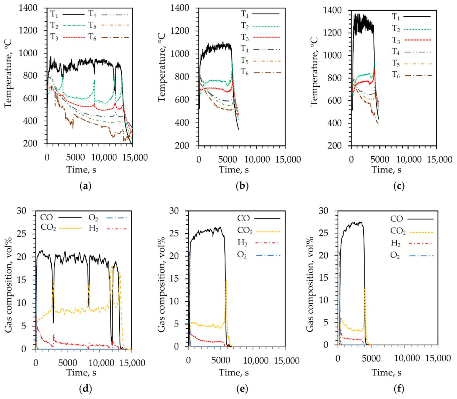
The first set of char gasification experiments were performed at different air fluxes using wood, sewage sludge and tires char to analyze char gasification under a supply of air. The obtained bed temperatures of wood char gasification and produced gas composition are presented in Figure 2. With the supply of air, the bed bottom temperature (T1) started to increase, indicating the beginning of gasification process and reached about 960 °C (Figure 2a). Meanwhile, the temperature at upper bed layers was lower approximately by 250 °C. After 2700 s, a peak in the T2 and T3 graph was observed. It was also observed after 8400 s, 12,000 s and 13,200 s. This peak could possibly be related to a low amount of supplied air (air flux 0.11 kg/(m2s)) causing uniform char oxidation per bed layer and shrinking char particles that move down, creating air spots in the upper bed layers. Additionally, the peaks in T2 and T3 graphs corresponded to CO decrease and CO2 increase (Figure 2d), which could be related to the combustion process. However, this tendency was not determined at higher air fluxes. Moreover, higher air flux led to a wider reaction zone as an increase of temperatures T2–T3 was parallel to the temperature T1 till the end of gasification process (Figure 2b,c). This also led to higher concentrations of CO and the CO concentrations were 25 vol% and 28 vol%, respectively, at the air flux of 0.21 and 0.32 kg/(m2s) (Figure 2e,f). It could be related to more intensive char gasification and ongoing Boudouard reaction (2) [23] as the temperatures in the reaction zone (T1) were ~1050 °C and ~1280 °C, respectively, at the air fluxes of 0.21 kg/(m2s) and 0.32 kg/(m2s).
C + CO 2 2 CO ,
However, a decrease in the CO2 concentration was determined as well at the air flux of 0.21 kg/(m2s) and the obtained concentration was about 4.5 vol% (Figure 2e). The highest CO2 concentration decrease (to 3.5 vol%) was determined at the air flux of 0.32 kg/(m2s) (Figure 2f). The CO concentration increased by 3.3 vol% in the produced gas from wood char in both cases. Meanwhile, the hydrogen concentrations were near identical at all investigated air fluxes (see Figure 2). Moreover, the duration of char gasification decreased by 55% and 72% at the air fluxes of 0.21 and 0.32 kg/(m2s), respectively, compared to the case of air flux of 0.11 kg/(m2s) (Figure 2).
Different results were obtained from gasifying sewage sludge and tires chars (Figure 3). Compared to the wood char case, bed temperature graphs of the sewage sludge indicated a reaction zone shift per the reactor height. It associated to a high ash content (Table 1) as the formed ash layer blocked the char movement down and the reaction zone shifted up, from the temperature measurement point of T1 to the point of T2 (Figure 3a). This tendency was also observed in graphs of gas yield (see Figure 3c). The formed temperature peak corresponded to the increase of CO and decrease of CO2 and vice versa. One of the possible reasons for this may have been insufficient Boudouard reaction (2) efficiency due to a lower surface area of the char in the gasification zone. Meanwhile, H2 concentration was stable, but the concentration was low compared to the results obtained with the wood char. In this case, the high ash content could also be attributed to a lower quality of the produced gas. Further experiments with sewage sludge char at higher air fluxes resulted in an agglomeration of the bed and the gasification process stopped. This problem is well known in regards to gasifying the raw sewage sludge, which consists of various metals (heavy, alkali) and non-metals and has a low ash melting temperatures [24]. A similar situation was also observed gasifying the tires char at lower air fluxes and the gasification process was only possible at air flux of 0.32 kg/(m2s) but still complicated (Figure 3b). During the gasification experiments, smaller particles of tire char were washed upwards by the gas stream due to low density of the char and it caused an unstable gasification process. The temperature fluctuations in the bed and changes in the gas composition were observed (Figure 3b,d). In first place, the main reaction zone was observed at temperature measurement points of T2–T3, but after 1400 s the gasification became unstable. The reaction zone shifted up according to the temperature increase in points of T4–T5 and a peak of O2 was observed in the producer gas indicating ineffective gasification (Figure 3d). According to the obtained results, the energy recovery from the waste tire char via the gasification process was too complicated.

3.2. Analysis of Char Gasification Supplying Air and Pyrolysis Gas

In order to intensify the char gasification process, the second set of the gasification experiments were performed by supplying air and pyrolysis gases (see Figure 1B). The gasification was performed using only two chars at different air fluxes: the sewage sludge char at 0.11 kg/(m2s) and the wood char at the air flux of 0.32 kg/(m2s). The obtained results supplying only air showed the shortest duration of the wood char gasification process using the air flux of 0.32 kg/(m2s), while the sewage sludge char gasification was not possible at higher air flux values due to clogging/agglomeration problem. The obtained temperature graphs and gas yield are presented in Figure 4. An additional supply of pyrolysis gas affected the gasification process of both chars causing an overall temperature drop in the bed compared to the cases with air supply only. At the beginning of the sewage sludge char gasification, the highest temperature of approximately 750 °C was determined at point T1 and after the supply of pyrolysis gas started to decrease. According to the readings of T3 thermocouple, the gasification zone shifted up and more intensive gasification process started at 3400 s. It led to a sudden temperature increase of the bed (see Figure 4a). With an increase of the bed temperature over 700 °C, a decrease of methane concentration was also determined (Figure 4c) and the gasification duration decreased by 44% compared to the results with air. It could be related to intensified Boudouard reaction (2) and CH4 decarburation reaction (3) as the CH4 concentration drop corresponded to a slight concentration increase of H2 and CO [25].
CH 4 C + 2 H 2 ,
Comparing the wood char gasification under supply of air and under supply of air and pyrolysis gas, the gasification tendency was near identical. The gasification reaction zone was also observed between the bed inlet and thermocouple T2. However, the temperature T1 and T2 decreased by approximately 200 °C and 60 °C, respectively, compared to the results with air. Further temperature values in other points (T3–T6) remained similar compared to the results obtained with air. Even though the gasification temperature was lower, the gasification duration kept almost the same. It was possibly due to supply pyrolysis gas, which led to tar reforming and possibly intensified char reforming reactions. The producer gas composition changes were not equal to the ratio of supplied air and pyrolysis gases (Table 2 and Figure 4d). Additionally, during the char gasification, the tar destruction was observed as the tar concentration was below the detection limit.

3.3. Air and Pyrolysis Gas Effect on Intensification of Char Gasification

To identify the gasification agent’s effect on char gasification process, the obtained results at different fluxes were analyzed and the obtained temperature profiles are presented in Figure 5. The temperature profile values were taken at 3000th second of the gasification process. The obtained temperature profiles clearly indicate the air flux impact on the bed temperature. The air flux increase from 0.11 kg/(m2s) to 0.32 kg/(m2s) led to increased bed bottom temperature (T1) from 880 °C to 1280 °C (Figure 5a). The temperature inside the bed decreased to 620 °C and 850 °C per 75 mm (T2), respectively, at the air flux of 0.11 and 0.32 kg/m2s and stabilized slowly through the rest of the bed.
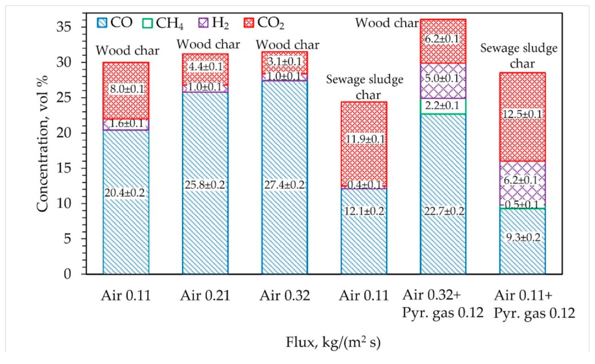
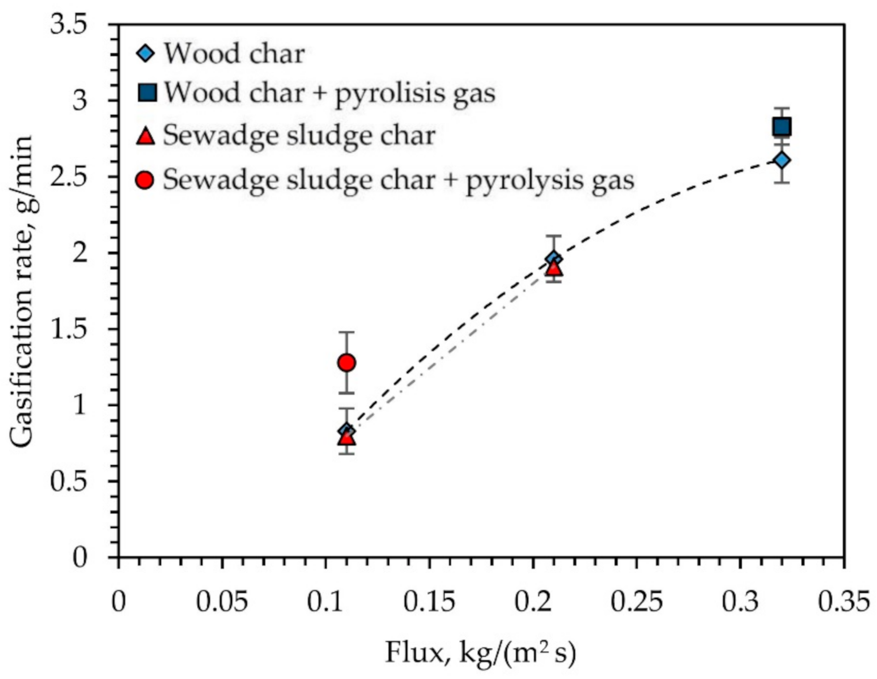
According to a previous study [26], char reforming reactions are more intense at temperatures 900°C and higher. Considering that, the use of air flux of 0.11 kg/m2s is effective, as temperatures along the bed are too low and the determined char gasification rate was only 0.8 g/min. An increase of air flux resulted in the growth of temperature which in turn affected CO2 and CO concentrations in the produced gas from char (Figure 6) and intensified ongoing reforming reactions as the gasification rate increased from 0.8 to 2.61 g/min (Figure 7). It also led to decreased char gasification duration by 67%. Using gasifying agent as air coupled with pyrolysis gases, the temperature at the inlet (T1) and in the upper layer (T2) of the wood char bed decreased to 1080 °C and to 790 °C, respectively, compared to the results with air. Temperature at upper layers remained near identical (Figure 5b). Similar temperature profiles have been presented by L. Van de steene [20]. Authors noted that the temperature drop in the wood char bed discussed above is caused by the endothermic reactions that occur in the gasification reaction zone. However, the gasification rate increased from 2.61 to 2.83 g/min compared to the results with air.
As it was described in the sections above, during the sewage sludge gasification the reaction zone shifted up along the bed and was mainly located between T3 and T4 points (Figure 5c). The supply of air coupled with pyrolysis gases led to decreased temperature by ~200 °C in the reaction zone as well, though the temperature at the inlet was higher. Overall, the gasification rate increased by 0.45 g/min compared to the case with air.
Considering these results, in both cases, pyrolysis gas enters the reactor where endothermic decomposition takes place. Consequently, this may be the reason for the temperature decrease. Additionally, gas phase reaction and only further decomposition of char to CO occurs (Figure 6). This change in process conditions is affected due to the gasifying agent. In case of air, the char gasification to CO takes place only in a CO2 environment and the partial pressure of this gas is the highest. It means that only CO2 reforming takes place. Upon introduction of pyrolysis gases and air mixture, the concentrations of active compounds of mixture change, thus changing the mechanism of reactions: several oxidation–steam reforming reactions, carbon dioxide and methane reforming take place simultaneously, the speed of which depend on concentration of their materials towards the char surface. It also explains the changes in the composition of producer gas (Figure 6). Taking into account the pyrolysis gas and producer gas composition, the CO2 concentration decreased by 1.68 vol% compared to the results with air as at the bed inlet the CO2 concentration was approximately 4.78 vol%. The H2 concentration also increased by 2.2 vol% as at the inlet concentration was around 2.8 vol% (Figure 6). Additionally, ongoing reforming reactions intensified char gasification rate. During the wood char and the sewage sludge gasification, it increased, respectively, by 56% and 8% compared to the results with air (Figure 7). Considering these findings, the supply of pyrolysis gases or syngas during char gasification enhances the producer gas composition and increase char gasification rate even at low air supply rates. Additionally, the supply of pyrolysis gas and air during the sewage sludge gasification drastically reduced the gasification duration by 50% compared to the results with air.

4. Conclusions

The present study was carried out to investigate the intensification of residual char gasification in a gasifier and enhance the producer gas composition. Three different types of char prepared from wood, sewage sludge and tire were examined under different conditions in a lab scale setup. It was determined that the air flux increase from 0.11 kg/(m2s) to 0.32 kg/(m2s) intensified the gasification process. The gasification rate increased from 0.8 to 2.61 g/min and resulted in the decreased duration of wood char gasification by 72%. At the same time, gas with the highest calorific value was obtained, where the lowest CO2 concentration was 3.1 vol%, and the highest CO concentration was 27.4 vol%.
The gasification of the sewage sludge char was only possible at the flux of 0.11 kg/(m2s) as at higher air fluxes the bed agglomeration occurred. The high ash content in the sewage sludge char resulted in the gasification zone drift through bed height. Moreover, the highest CO2 (11.9 vol%) and lowest CO concentrations (12.1 vol%) were determined in the produced gas from the sewage sludge char. However, the gasification rate was near identical to the wood char case, but the char gasification duration was shorter by 13.3%. Complicated gasification was determined using the tire char as the smaller particles of tire char were washed upwards by the gas stream and the gasification process became unstable and ineffective.
An additional introduction of pyrolysis gas into the char gasifier changed the process conditions. The change in concentrations of mixture compounds resulted in change of reaction mechanism and oxidation–water vapor reactions, carbon dioxide and methane reforming took place simultaneously. It led to the decreased temperature of the wood char bed and the sewage sludge bed, respectively, from 1280 °C to 1080 °C and from 880 °C to 700 °C. However, the gasification rate increased in both cases and the highest improvement was determined during the sewage sludge gasification. The gasification rate increased from 0.8 to 1.25 g/min. Analysis of the produced gases revealed that the most effective carbon dioxide (CO2) conversion is at the temperature of 900–1200 °C in all cases of char gasification. Moreover, the use of pyrolysis gas coupled with air as the gasifying agent enhanced the composition of produced gas from char compared to the results with air. The CO2 concentration decreases by 1.68 vol%, H2 concentration increased by 2.8 vol% and the tar concentration was below the detection limit.

Author Contributions

Conceptualization, N.S. and R.P.; methodology, K.Z.; software, N.S.; validation, N.S. and K.Z.; formal analysis, R.P. and K.Z.; investigation, K.Z.; resources, N.S.; data curation, K.Z. and R.P.; writing—original draft preparation, K.Z. and R.P.; writing—review and editing, R.P.; visualization, K.Z.; supervision, N.S.; project administration, N.S.; funding acquisition, R.P. All authors have read and agreed to the published version of the manuscript.

Funding

This project has received funding from European Regional Development Fund (project No. 01.2.2-LMT-K-718-01-0005) under grant agreement with the Research Council of Lithuania (LMTLT).

Institutional Review Board Statement

Not applicable.

Informed Consent Statement

Not applicable.

Data Availability Statement

The data that support the findings of this study are available from the corresponding author, [R.P.], upon reasonable request.

Acknowledgments

Special thanks goes to the rest project team members: investigators: Martynas Lelis, Andrius Tamošiūnas, Dovilė Gimžauskaitė, Vilma Snapkauskienė.

Conflicts of Interest

The authors declare no conflict of interest.

References

  1. Koniuszy, A.; Hawrot-Paw, M.; Podsiadło, C.; Sędłak, P.; Możdżer, E. Gasification of Cup Plant (Silphium perfoliatum L.) Biomass—ENERGY Recovery and Environmental Impacts. Energies 2020, 13, 4960. [Google Scholar] [CrossRef]
  2. Chojnacki, J.; Najser, J.; Rokosz, K.; Peer, V.; Kielar, J.; Berner, B. Syngas Composition: Gasification of Wood Pellet with Water Steam through a Reactor with Continuous Biomass Feed System. Energies 2020, 13, 4376. [Google Scholar] [CrossRef]
  3. Cerone, N.; Zimbardi, F.; Contuzzi, L.; Baleta, J.; Cerinski, D.; Skvorčinskienė, R. Experimental investigation of syngas composition variation along updraft fixed bed gasifier. Energy Convers. Manag. 2020, 221, 113116. [Google Scholar] [CrossRef]
  4. Ardolino, F.; Arena, U. Biowaste-to-Biomethane: An LCA study on biogas and syngas roads. Waste Manag. 2019, 87, 441–453. [Google Scholar] [CrossRef] [PubMed]
  5. Michailos, S.; Walker, M.; Moody, A.; Poggio, D.; Pourkashanian, M. Biomethane production using an integrated anaerobic digestion, gasification and CO2 biomethanation process in a real waste water treatment plant: A techno-economic assessment. Energy Convers. Manag. 2020, 209, 112663. [Google Scholar] [CrossRef]
  6. Chen, S.; Zhao, Z.; Soomro, A.; Ma, S.; Wu, M.; Sun, Z.; Xiang, W. Hydrogen-rich syngas production via sorption-enhanced steam gasification of sewage sludge. Biomass Bioenergy 2020, 138, 105607. [Google Scholar] [CrossRef]
  7. Lin, C.-L.; Chou, J.-D.; Iu, C.-H. Effects of second-stage bed materials on hydrogen production in the syngas of a two-stage gasification process. Renew. Energy 2020, 154, 903–912. [Google Scholar] [CrossRef]
  8. dos Santos, R.G.; Alencar, A.C. Biomass-derived syngas production via gasification process and its catalytic conversion into fuels by Fischer Tropsch synthesis: A review. Int. J. Hydrog. Energy 2020, 45, 18114–18132. [Google Scholar] [CrossRef]
  9. Speight, J.G. Gasifier Types. In Gasification of Unconventional Feedstocks; Elsevier: Amsterdam, The Netherlands, 2014; pp. 54–90. [Google Scholar]
  10. Sharma, P.; Gupta, B.; Pandey, M.; Singh Bisen, K.; Baredar, P. Downdraft biomass gasification: A review on concepts, designs analysis, modelling and recent advances. Mater. Today Proc. 2020. [Google Scholar] [CrossRef]
  11. González-Vázquez, M.P.; García, R.; Gil, M.V.; Pevida, C.; Rubiera, F. Comparison of the gasification performance of multiple biomass types in a bubbling fluidized bed. Energy Convers. Manag. 2018, 176, 309–323. [Google Scholar] [CrossRef]
  12. Khan, A.A.; de Jong, W.; Jansens, P.J.; Spliethoff, H. Biomass combustion in fluidized bed boilers: Potential problems and remedies. Fuel Process. Technol. 2009, 90, 21–50. [Google Scholar] [CrossRef]
  13. Kumar, A.; Jones, D.; Hanna, M. Thermochemical Biomass Gasification: A Review of the Current Status of the Technology. Energies 2009, 2, 556–581. [Google Scholar] [CrossRef] [Green Version]
  14. Plis, P.; Wilk, R.K. Theoretical and experimental investigation of biomass gasification process in a fixed bed gasifier. Energy 2011, 36, 3838–3845. [Google Scholar] [CrossRef]
  15. Cetin, E.; Moghtaderi, B.; Gupta, R.; Wall, T. Influence of pyrolysis conditions on the structure and gasification reactivity of biomass chars. Fuel 2004, 83, 2139–2150. [Google Scholar] [CrossRef]
  16. Striugas, N.; Zakarauskas, K.; Džiugys, A.; Navakas, R.; Paulauskas, R. An evaluation of performance of automatically operated multi-fuel downdraft gasifier for energy production. Appl. Therm. Eng. 2014, 73, 1151–1159. [Google Scholar] [CrossRef]
  17. Khiari, B.; Jeguirim, M.; Limousy, L.; Bennici, S. Biomass derived chars for energy applications. Renew. Sustain. Energy Rev. 2019, 108, 253–273. [Google Scholar] [CrossRef]
  18. Assima, G.P.; Marie-Rose, S.; Lavoie, J.-M. Role of fixed carbon and metal oxides in char during the catalytic conversion of tar from RDF gasification. Fuel 2018, 218, 406–416. [Google Scholar] [CrossRef]
  19. Zhang, S.; Asadullah, M.; Dong, L.; Tay, H.-L.; Li, C.-Z. An advanced biomass gasification technology with integrated catalytic hot gas cleaning. Part II: Tar reforming using char as a catalyst or as a catalyst support. Fuel 2013, 112, 646–653. [Google Scholar] [CrossRef]
  20. Henriksen, U.; Ahrenfeldt, J.; Jensen, T.K.; Gøbel, B.; Bentzen, J.D.; Hindsgaul, C.; Sørensen, L.H. The design, construction and operation of a 75kW two-stage gasifier. Energy 2006, 31, 1542–1553. [Google Scholar] [CrossRef] [Green Version]
  21. Van de Steene, L.; Tagutchou, J.P.; Mermoud, F.; Martin, E.; Salvador, S. A new experimental Continuous Fixed Bed Reactor to characterise wood char gasification. Fuel 2010, 89, 3320–3329. [Google Scholar] [CrossRef] [Green Version]
  22. Teixeira, G.; Van de Steene, L.; Martin, E.; Gelix, F.; Salvador, S. Gasification of char from wood pellets and from wood chips: Textural properties and thermochemical conversion along a continuous fixed bed. Fuel 2012, 102, 514–524. [Google Scholar] [CrossRef] [Green Version]
  23. Roncancio, R.; Gore, J.P. CO2 char gasification: A systematic review from 2014 to 2020. Energy Convers. Manag. X 2020, 100060. [Google Scholar] [CrossRef]
  24. Kim, D.; Park, D.; Lim, Y.; Park, S.; Park, Y.-S.; Kim, K. Combustion Melting Characterisation of Solid Fuel Obtained from Sewage Sludge. Energies 2021, 14, 805. [Google Scholar] [CrossRef]
  25. Abánades, A.; Ruiz, E.; Ferruelo, E.M.; Hernández, F.; Cabanillas, A.; Martínez-Val, J.M.; Rubio, J.A.; López, C.; Gavela, R.; Barrera, G.; et al. Experimental analysis of direct thermal methane cracking. Int. J. Hydrog. Energy 2011, 36, 12877–12886. [Google Scholar] [CrossRef] [Green Version]
  26. Striūgas, N.; Zakarauskas, K.; Džiugys, A.; Grigaitienė, V. Experimental modelling of tar destruction with addition of CO2 for application in the biomass gasification system. Appl. Therm. Eng. 2013, 61, 213–219. [Google Scholar] [CrossRef]
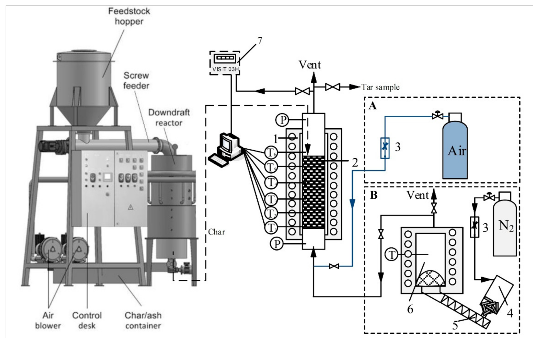
Figure 1. The downdraft gasifier (left) and experimental rig of char gasification (right) using different gasification agents: (A) air and (B) pyrolysis gases + air: 1—an electrically heated furnace; 2—a closed stainless-steel tube with char; 3—a mass flow controller; 4—a biomass pellet container; 5—a screw conveyer; 6—a pyrolysis reactor, 7—a gas analyzer.
Energies 14 01983 g001
Figure 2. Bed temperatures and gas yield during wood char gasification at air flux of (a,d) 0.11 kg/(m2s) (b,e) 0.21 kg/(m2s) and (c,f) 0.32 kg/(m2s).
Energies 14 01983 g002
Figure 3. Bed temperatures and gas yield during (a,c) sewage sludge char gasification at air flux of 0.11 kg/(m2s) and (b,d) tires char gasification at air flux of 0.32 kg/(m2s)
Energies 14 01983 g003
Figure 4. Bed temperatures and gas yield during (a,c) the sewage sludge char gasification at air flux of 0.11 kg/(m2s) and the wood (b,d) char gasification at 0.31 kg/(m2s), respectively, supplying air coupled with pyrolysis gases
Energies 14 01983 g004
Figure 5. Temperature profiles along the bed of (a)wood char at different air fluxes; (b)wood char at the air flux and the flux of air coupled with pyrolysis gas; (c) sewage sludge at the air flux and the flux of air coupled with pyrolysis gas.
Energies 14 01983 g005
Figure 6. Composition of producer gas from wood char and sewage sludge char at different flux of gasifying agent.
Energies 14 01983 g006
Figure 7. Effect of air flux on gasification rate of different char.
Energies 14 01983 g007
Table 1. Used char properties.
Wood CharSewage Sludge CharTire Char
Ash content, %2.250.110.3
HHV, MJ/kg33.816.331.4
Table 2. Composition of dry producer gas from pyrolysis reactor.
CompoundConcentration
H2, vol%11.2 ± 0.1
CO, vol%16.3 ± 0.2
CH4, vol%9.1 ± 0.1
CO2, vol%19.1 ± 0.1
N2, vol%44.3 ± 0.4
Tar, g/m321.1 ± 1.2
Publisher’s Note: MDPI stays neutral with regard to jurisdictional claims in published maps and institutional affiliations.