Abstract
Thermal barrier coatings (TBCs) have been investigated both experimentally and through simulation for mixing controlled combustion (MCC) concepts as a method for reducing heat transfer losses and increasing cycle efficiency, but it is still a very active research area. Early studies were inconclusive, with different groups discovering obstacles to realizing the theoretical potential. Nuanced papers have shown that coating material properties, thickness, microstructure, and surface morphology/roughness all can impact the efficacy of the thermal barrier coating and must be accounted for. Adding to the complexities, a strong spatial and temporal heat flux inhomogeneity exists for mixing controlled combustion (diesel) imposed onto the surfaces from the impinging flame jets. In support of the United States Department of Energy SuperTruck II program goal to achieve 55% brake thermal efficiency on a heavy-duty diesel engines, this study sought to develop a deeper insight into the inhomogeneous heat flux from mixing controlled combustion on thermal barrier coatings and to infer concrete guidance for designing coatings. To that end, a co-simulation approach was developed that couples high-fidelity computational fluid dynamics (CFD) modeling of in-cylinder processes and combustion, and finite element analysis (FEA) modeling of the thermal barrier-coated and metal engine components to resolve spatial and temporal thermal boundary conditions. The models interface at the surface of the combustion chamber; FEA modeling predicts the spatially resolved surface temperature profile, while CFD develops insights into the effect of the thermal barrier coating on the combustion process and the boundary conditions on the gas side. The paper demonstrates the capability of the framework to estimate cycle impacts of the temperature swing at the surface, as well as identify critical locations on the piston/thermal barrier coating that exhibit the highest charge temperature and highest heat fluxes. In addition, the FEA results include predictions of thermal stresses, thus enabling insight into factors affecting coating durability. An example of the capability of the framework is provided to illustrate its use for investigating novel coatings and provide deeper insights to guide future coating design.
1. Introduction
Thermal barrier coatings (TBCs) have been studied for decades as a potential method to reduce heat transfer losses in internal combustion engines (ICEs) and allow for more efficient conversion of fuel energy into mechanical work. Early studies [1,2,3,4] investigated the effect of monolithic ceramic coatings applied to the piston crown, cylinder head, and liner surfaces with the aim to develop an adiabatic engine. The results from such studies were mixed, with several indicating a thermal efficiency improvement, while others showed that TBCs had a detrimental impact on efficiency. Several authors [3,4,5] noted that thick monolithic coatings lead to increased wall temperatures compared to a metal piston throughout the cycle. The increased surface temperature during gas exchange leads to an increase in intake charge heating, leading to decreased trapped mass and a lower volumetric efficiency. Secondarily, with a reduction in heat transfer, not all the “saved” energy goes to useful work, and a portion is lost through the exhaust enthalpy [5]. In 1989, Kamo, Assanis, and Bryzik [6] conducted a numerical study to investigate the effect of TBC thickness on the surface temperature of the TBC and found that thin TBCs (100–300 µm) rather than thicker TBCs (500 + µm) could generate a dynamic surface temperature swing, achieving a targeted reduction of the temperature delta between the wall and gas during late compression/early expansion. A numerical study by Kosaka et al. [7] further pursued this concept with a different approach by investigating the impacts of TBC material properties, including porosity and coating thicknesses on heat transfer reduction. A STAR-CD computational fluid dynamics (CFD) model was coupled with a wall temperature solver and identified that thin, porous TBCs (≈100–250 µm) with material properties akin to yttria-stabilized zirconia (YSZ) demonstrated a transient surface temperature that mimicked that of the in-cylinder gasses. Previous experimental work by Filipi et al. [8] demonstrated further efficiency gains in the gasoline fueled homogeneous charge compression ignition (HCCI) engine when YSZ was replaced by gadolinium zirconate (GdZr). The latter is in the category of advanced coatings with more advantageous thermal properties than yttria-stabilized zirconia, a well-established and widely used coating for ICE applications. The lower conductivity of GdZr led to increased amplitude of the surface temperature swing and the resulting fuel efficiency gains were in the range of 2 percentage points for typical HCCI operating conditions [8]. Somhorst et al. [9] investigated gadolinium zirconate for heavy-duty diesel engine application and found that the coating’s ability to reduce heat transfer losses and improve efficiency is strongly dependent on surface roughness. Thin TBCs have been denoted as “temperature swing coatings” as they are able to track the temperature of the gasses in the cylinder, rising during compression and combustion, and decreasing during expansion and gas exchange. This allows the thin TBC to sidestep the unfortunate volumetric efficiency penalty from the hot walls in the chamber, decreasing the charge density during intake. The challenge remains to achieve the desired temperature swing behavior within the physical constraints of real-world thermophysical properties and realistic levels of porosity.
In order to investigate the impact of TBCs on combustion, several studies have developed cycle simulations that link CFD model with some form of finite element analysis (FEA), finite difference heat equation solver, or lumped model to capture the variation in surface temperature from the TBC, as well as the subsequent effect of the surface temperature on combustion. Kundu et al. [10] modeled a heavy-duty diesel engine using the CONVERGE Conjugate heat transfer model. Their approach averaged the calculated heat transfer boundary conditions temporally and calculated the steady-state surface temperature for a metal or TBC-coated piston. This methodology does not allow for the calculation of the transient temperature swing effect, rather just the thermal resistance effect on the steady-state surface temperature. They found that increasing the head and bowl temperature led to higher thermal efficiency, while increasing the liner temperature decreased thermal efficiency. A parametric study found that >53% of heat transfer losses can be recovered with a 0.2 or 0.7 mm coating. Baldissera et al. [11] used steady-state convective boundary conditions to predict the temperature field of the piston and thermal barrier coating to understand the stresses developed in the piston. Taibani et al. [12] used a 0D GT Power model to generate 1D boundary conditions for 1D heat conduction solver—this surface temperature prediction was then fed back into GT Power to predict the reduction in heat transfer. Taibani et al. [12] found that a hypothetical coating that had 1/9 of the conductivity and volumetric heat capacity of YSZ could reduce heat transfer losses by ≈45%. Killingsworth [13] employed the lumped capacitance method available in CONVERGE CFD to estimate the effect of a thermal barrier coating on homogeneous charge compression ignition with a YSZ coating, noting that this method ignores the effect of volumetric heat storage (ρ*Cp). All of these methods employed either a spatial or temporal averaging process to either reduce computational cost (temporal averaging for CFD) or because the development of the boundary conditions (BCs) did not have the fidelity to generate reasonable BCs (spatial averaging in GT Power). A variety of previous studies are provided in Table 1 to illustrate a range of thermophysical properties and peak temperatures for previous simulations regarding diesel engine pistons.

Table 1.
Literature review for thermal barrier coating (TBC) simulations.
The aim of this study is to develop a methodology for predicting spatially and temporally resolved boundary conditions at the coating surface and use it to guide coating development, as well as to subsequently investigate the impact of a thermal barrier coating on a high-load, high-efficiency mixing controlled combustion (MCC or diesel) engine. The impetus is provided by the need for a systematic study linking the key thermophysical properties of the coating with the temperature swing behavior, thus ultimately supporting the down selection of the material and optimization of the coating thickness and/or morphology. Through the co-simulation approach, the heat transfer and combustion/gas modeling can be pursued in sequence, allowing for high fidelity predictions without a limiting time step imposed by one model on the other. The co-simulation approach was used to estimate the peak surface temperature of the high-performance thermal barrier coating (up to 1200K), the heat transfer reduction (≈9%), and the effect of the TBC on combustion and efficiency. For this work, a gadolinium zirconate (GdZr) thermal barrier coating was selected to illustrate the methodology.
2. Methods
This study develops a framework that can characterize the spatial and temporal heat transfer impacts of a coated component in a combustion chamber and develop deeper insights into the extreme localized conditions that drive the down selection of candidate materials for coatings. In other words, while maximizing the amplitude of the temperature swing is the stated goal, the peak local temperature may exceed the phase stability or melting limit for a given material and therefore has to be considered in the coating development process. For this work, the coated component is the piston crown derived from a state-of-the-art 13 L production heavy-duty diesel engine. An iterative co-simulation approach was developed that couples a CONVERGE CFD model of the engine cylinder with an Abaqus FEA model of the metal piston and TBC to examine the effects of coating properties on the temperature swing behavior, and in turn quantify the impact on combustion heat loss and thermal efficiency.
The CFD and FEA models are indirectly coupled and run independently in an iterative approach. Spatiotemporally resolved thermal boundary conditions at the gas–solid interface of the coated surface are passed between the two models. The CFD model provides near-wall gas temperatures and heat transfer coefficient, and the FEA model provides surface temperature of the coated piston crown. This methodology was employed to eliminate the effect of time-scale differentials between the CFD and FEA solvers while providing high-fidelity prediction required for analysis of the TBCs applied to the engine with a highly heterogenous charge during combustion.
The initial run of the CFD model assumes a constant, uniform piston surface temperature. Multiple engine cycles are simulated to ensure steady-state operation is achieved. Near-wall gas temperature and gas-side heat transfer coefficient across the piston crown are output from the CFD model at each crank angle during the final engine cycle. These boundary conditions are subsequently processed and passed along to the FEA model as convective flux boundary conditions on the piston. The FEA model solves for the temperature field throughout the solid piston and coating over a full engine cycle. The spatially and temporally varying surface temperature field predicted by the FEA model for the full engine cycle are subsequently processed and provided as input to the CFD model for another iteration. Iterations continue until the results reach quasi-steady state. Two iterations were required to achieve a steady state solution for the cases provided in this paper. At each step, the sub models were each run to convergence. In other words, the FEA model ran multiple cycles using the same boundary conditions but with the initial model temperature being updated from each previous run. Convergence to steady state was identified when the averaged surface temperature change between the start and end of cycle was less than 1%. This also produced accurate predictions of spatial variations and captured the local extremes, which are critical for coating selection and durability.
To generate relevant comparisons between the baseline metal engine configuration and the thermal barrier coated piston, two FEA piston models were developed: one for the bare metal piston, and another with a 100 μm thick thermal barrier coating applied atop the crown. The CFD model uses the same piston geometry for both cases in order to maintain the same compression ratio. The 2 models are used such that a fair comparison can be drawn between the metal and TBC-coated engine configurations, ensuring the same level of spatial and temporal fidelity for baseline metal and TBC cases. For the comparison cases, the validated steady state temperature field was used to initialize the model. The FEA model time step was 1 crank angle, and therefore the CONVERGE boundary conditions are the temporal average over 1 crank angle degree.
2.1. Modeling Methodology—CFD and FEA
The CFD model of one cylinder of the Detroit DD13 engine was created using the commercial CFD software tool CONVERGE (v2.4) [17]. Model geometry was developed from Computer Aided Design (CAD) models of (relevant) production engine parts provided by Daimler in support of this study. Additional model inputs provided by Daimler include valve lift profiles and injector nozzle geometry. For model validation, Daimler provided baseline steady-state experimental data from a dyno-mounted engine over the full speed-load operating map including crank-angle-resolved pressure measurements from the cylinder and the intake and exhaust manifolds; intake and exhaust temperatures; air flow rate; and fuel injection data such as timing, rate, etc.
CONVERGE uses a cut-cell approach for real-time mesh generation. A moderately detailed mesh resolution strategy was used with a base grid of 2 mm. Refined embedding to 0.5 mm was applied at the valve seats to resolve high-speed flows during valve opening and closing. Adaptive mesh refinement to 0.5 mm was applied in areas with velocity sub-grid gradients exceeding 5 m/s. Meshing of the injector sprays was refined to 1 mm. Further refinement of the reaction zone was achieved with adaptive mesh refinement to 0.5 mm in areas with sub-grid temperature gradients exceeding 10 K and/or OH¯ concentration gradients exceeding 1 × 10⁻⁶. Finally, additional fixed embedding to 1 mm was applied at the piston crown to better resolve near-wall conditions. This approach resulted in a maximum count of approximately 2 million cells during the engine cycle simulation.
Typical modeling approaches for mixing-controlled, compression ignition engine operation available in CONVERGE were used to simulate engine processes and behavior. Turbulence interactions were modeled with the k-ε Reynolds-averaged Navier–Stokes (RANS) model. Fuel spray into the engine cylinder was modeled with a Lagrangian parcel approach with a single-component liquid surrogate of n-heptane used to represent diesel fuel. Fuel distribution immediately leaving the injector was treated using the “blob” approach with downstream breakup modeled using the Kelvin–Helmoltz and Rayleigh–Taylor (KH-RT) submodels [18]. The dynamic droplet drag model and no time counter (NTC) droplet collision model [19] were also used. Spray–wall interactions were simulated with the O’Rourke wall-film model [20]. Evaporation of the liquid fuel parcels into n-heptane vapor was simulated with the Frossling evaporation model without boiling [21]. Combustion was simulated using by solving chemical kinetics within the CFD cells using a well-stirred reactor model [22] with a multi-zone approach [23] and a moderately detailed n-heptane kinetic mechanism with 144 species and 900 reactions.
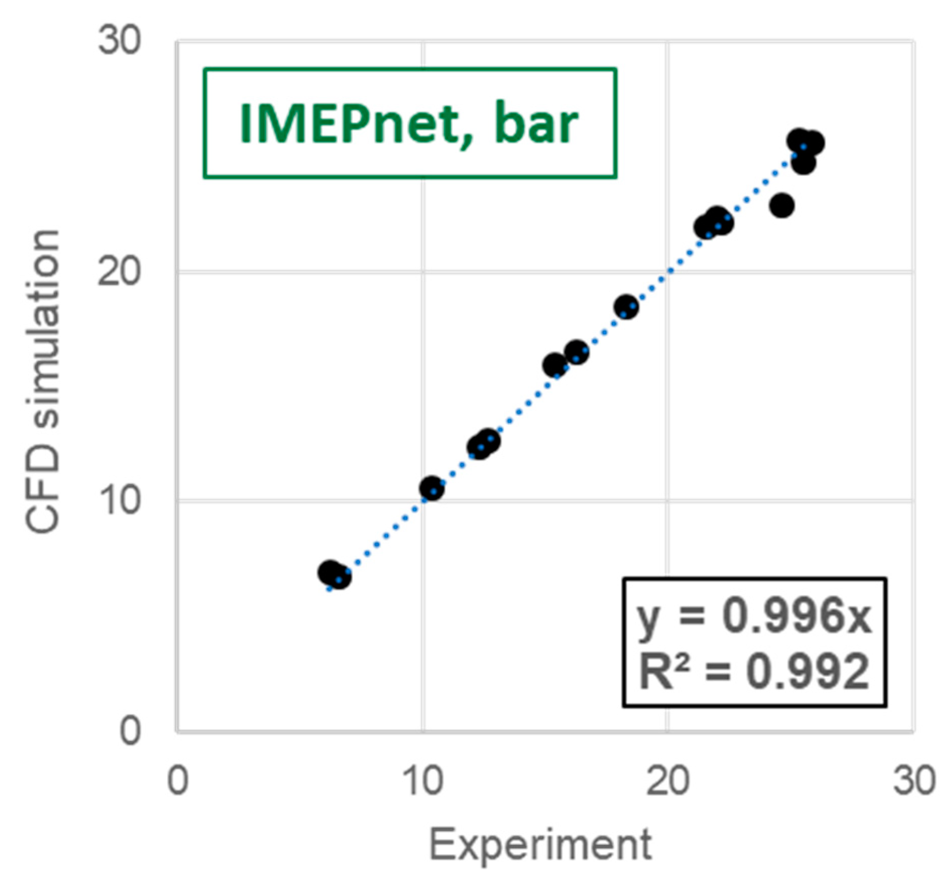
CFD model validation was performed at 15 speed-load operating points across the full operating range of the engine including the target road-load cruise point (1100 revolutions per minute [rpm], 50% load) and the peak torque point used in this study (1000 rpm, 100% load). Comparisons were made between model predictions and steady-state engine dynamometer data provided by Daimler, including cylinder conditions at intake valve closing, cylinder pressure and heat release rate traces, and overall performance metrics such as indicated mean effective pressure (IMEP) and combustion rate profiles. Figure 1 provides a comparison of net IMEP showing overall excellent agreement at the 15 speed-load points.
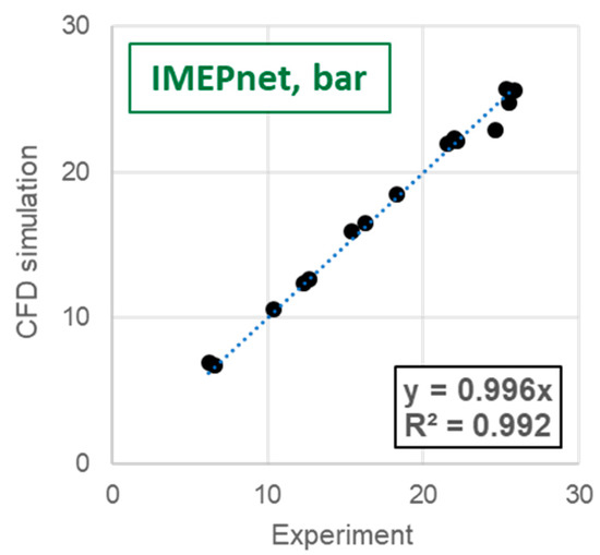
Figure 1.
Comparison of computational fluid dynamics (CFD) model predictions and experimental measurements of net indicated mean effective pressure to show model validation across a wide speed and load range.
The transfer of the temporal and spatial boundary condition data between the two models was accomplished through specially developed Matlab and Python scripts. Crank angle-resolved heat transfer data (including gas-side heat transfer coefficient and near-wall temperature) at each mesh node on the piston surface was output from CONVERGE. A Matlab script was used to separate this data into individual data files for each crank angle composed of a 4-column nodal file with X, Y, and Z co-ordinates and the variable value that could be imported to Abaqus. A Python script was run within Abaqus that programmatically generated a new time step, imposed an interpolated convective flux boundary condition field (HTC and Tgas) from the text files, and then removed the previous time step flux boundary condition. After completing the simulation, the Abaqus FEA model provided temporal and spatially resolved piston surface temperatures as output. A final Matlab script was used to convert the native Abaqus output into a text file that was directly imported into CONVERGE for the next iteration.
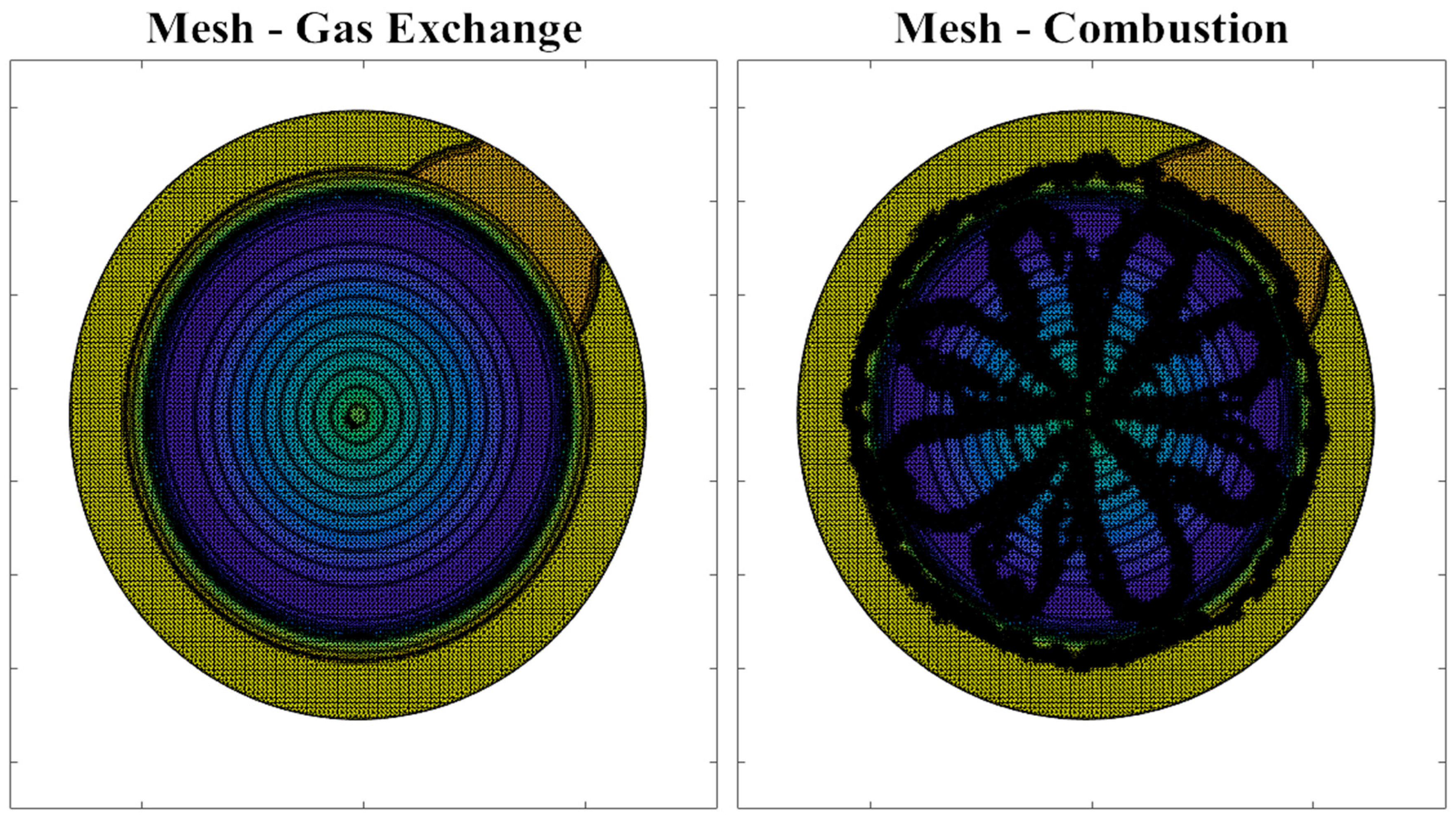
As mentioned above, the CFD model uses a 1 mm gas-side grid at the piston surface with adaptive mesh refinement to 0.5 mm in regions with high sub-grid gradients in velocity, temperature, and OH¯ concentration. This produces a variable set of output node locations throughout the engine cycle, as shown in Figure 2. The FEA model uses a static grid with a higher nodal density to accurately capture the dynamic surface temperature profile of the thermal barrier coating. The mapping process outlined above allows for interpolation between the two meshes. Grid-convergence studies were performed to optimize the grid resolution of both models. A mesh density of 70,000 nodes in the FEA model was found to be sufficient to provide accurate interpolation of boundary conditions from the CFD data. The same FEA mesh was used for the metal and TBC case, wherein a shell element layer was imposed on the crown of the piston, with assumed perfect heat conduction at the interface.
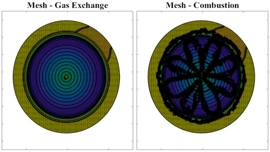
Figure 2.
Adaptive mesh refinement impacts on mesh density as shown for lowest vs. highest mesh density.
The FEA model was developed in Abaqus 6.14 using the same CAD Model of the 13 L engine piston. The meshing routine used a mesh bias, wherein element sizes were at a minimum on the piston crown, and subsequently increased in size away from the crown surface. After a mesh sensitivity study, the final base metal piston model had 100,000 + DC3D4 4-node linear heat transfer tetrahedron elements on the order of 2 mm on the surface, and up to 10 mm for the piston skirt. For the TBC model, 16,965 DS3/DS4 offset shell elements were added to the piston crown, with an assumed perfect heat conduction constraint between the piston crown surface and underside of the TBC. The TBC shell elements were on the order of 1 mm. The shell elements were solved using Simpson’s integration routine during the analysis with 19 integration points for each element within the TBC shell.
The baseline FEA model was validated for the metal piston using steady-state experimental measurements of piston temperature with a temp-plug instrumented piston at 1000 rpm full load. The temp-plug measurements indicated the maximum temperatures observed during operation at various locations, and were used for initial validation of boundary conditions for the FEA simulation, shown in Table 2.
Table 2.
Templug experimental data compared with finite element analysis (FEA) surface temperature at similar locations.
Templug screws were installed in a modified piston that shared the same geometry as the simulated pistons. Templug measurements are used to identify maximum service temperature, and as such, the engine was run at rated full load for 1 h to correctly time cycle the plug. The templug measurements are shown with their associated error in Table 2, and their respective values are compared to the metal time-averaged temperature solution from the FEA model. The exact location of the templug relative to the injector holes to identify if the templug was underneath an impinging flame jet was not provided, and as such, an average of the FEA temperature along the circumference running through the templug location was taken for the comparison.
For the validation case, the gas side boundary conditions for the piston crown were taken as the spatially resolved but temporally averaged heat flux from the CFD model outputs for the same speed/load case. The initial validation boundary conditions for backside (non-piston crown) convective heat flux were identified from literature [24,25], then tuned such that the simulated steady state case was within close agreement with the experimentally measured temperatures. The final values and locations for these back-side conditions are shown in Table 3 and in Figure 3, respectively.
Table 3.
Steady-state convective heat flux boundary conditions imposed on piston.

Figure 3.
Locations of steady-state boundary conditions: initial values were taken from Gonera et al. [24], then modified to match experimental temperature plug measurement data.
2.2. Details of Comparision Cases
Once validated for the metal piston, the modeling approach was applied to compare engine performance at 1000 rpm and full load using the stock metal piston and a stock piston with a 100 μm coating of gadolinium zirconate (GdZr). Material properties for the metal and GdZr coating are shown in Table 4.
Table 4.
Material properties for FEA model.
To isolate the impact of the GdZr coating on overall engine performance, we kept model parameters the same for the two cases. In the CFD model, the same compression ratio, fuel injection timing and quantity, port pressure boundary conditions, and thermal boundary conditions (on all surfaces other than the piston) were used for the metal and coated piston cases. Back-side thermal boundary conditions and grid resolution were kept the same in the FEA model. Only the thermal boundary conditions on the piston crown in both models changed between cases.
3. Results and Case Study
The following sections present the FEA and CFD simulation results after convergence. First, the temperature fields for the metal and TBC cases were compared to highlight the magnitude of temperature swing exhibited by a gadolinium zirconate (GdZr) coating. Second, the TBC effects on combustion were analyzed from the CFD results, showing the instantaneous energy breakdown. Finally, the boundary conditions were used to estimate the required temperature swing to meet a target heat flux reduction.
3.1. FEA Temperature Field Solutions
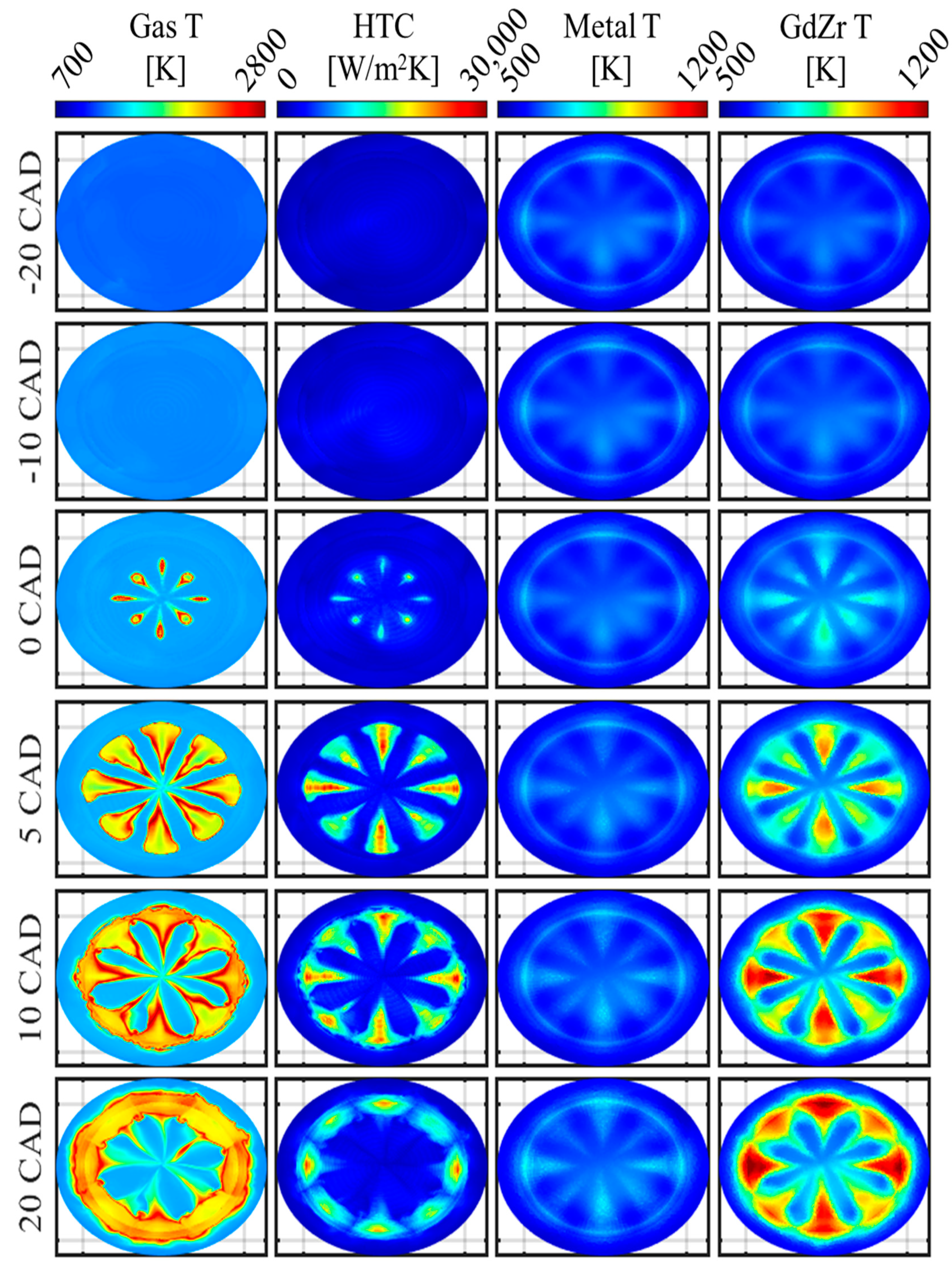
The additional fidelity gained by coupling CFD spatially and temporally varying boundary conditions shows the effect of the characteristic inhomogeneity of mixing controlled (diesel) combustion. 0D and 1D modeling of thermal barrier coatings in a diesel environment fall short of holistically capturing the heat transfer as they do not account for the spatial effects of impinging flame jets affecting the local heat transfer significantly. Figure 4 shows several time-stamped surface boundary conditions and temperature profiles for the metal piston (column 3) and coated piston (column 4). The effects of the impinging flame were captured in both simulations; however, with the low-thermal conductivity, low-volumetric heat capacity thermal barrier coating, the surface temperature profile demonstrates a large dynamic surface temperature swing, reaching a maximum intracycle amplitude of ≈600K.
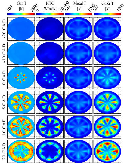
Figure 4.
Boundary conditions and surface temperature profiles for full load 1000 rpm case. Column one represents the fluid cell temperature closest the piston surface, column two represents the heat transfer coefficient imposed at the wall nodes, column three shows the surface temperature of the metal piston, and column four shows the surface temperature of the 100-micron gadolinium zirconate coating.
For the full load case depicted in Figure 4, the CFD predicts that peak heat fluxes at certain locations can approach 40 MW/m2 during peak combustion impingement on the piston. While these values do exceed the typical estimated range for a 1D correlation, such as Hohenberg [26] or Woschni [27], which are averaged over the entire combustion chamber surface area, experimental results by Binder et al. [28] using phosphor thermometry demonstrated that the location under impinging burning jets can experience heat flux exceeding 60 MW/m2. The extreme magnitude of the local heat fluxes on the surface of the low-thermal conductivity, low-heat capacity coating led to instantaneous surface temperatures exceeding 1100 K. The amplitude of the intracycle temperature swing exceeded 600K. Interestingly, other locations between the adjacent sprays or the squish region on the surface of the coated piston were relatively unaffected by combustion, only showing a ≈20–60 K rise in surface temperature over the cycle. This high spatial variation was also seen for the metal piston, although the peak magnitude change was significantly reduced. Closer investigation of the metal and gadolinium zirconate surface temperature profiles in Figure 4 show four impinging flame jets at the 12, 3, 6, and 9 o’clock positions, with larger surface area at a higher temperature. This is postulated to be an effect of the valve positions, which were centrally located above the 1:30, 4:30, 7:30, and 10:30 positions. These valves were slightly recessed into the cylinder head, meaning there was a larger volume of space for the diffusion flame to move through, and as such, the flame was not as restricted and forced to impinge on the surface of the piston as early in the combustion process, or for as long. Visualizations of the CFD results show the differences in shape for the spray plumes and flame fronts that pass under the valves and expand upwards into the valve pocket volume and away from the piston.
3.2. TBC Engine Cycle Impacts Predicted with CFD
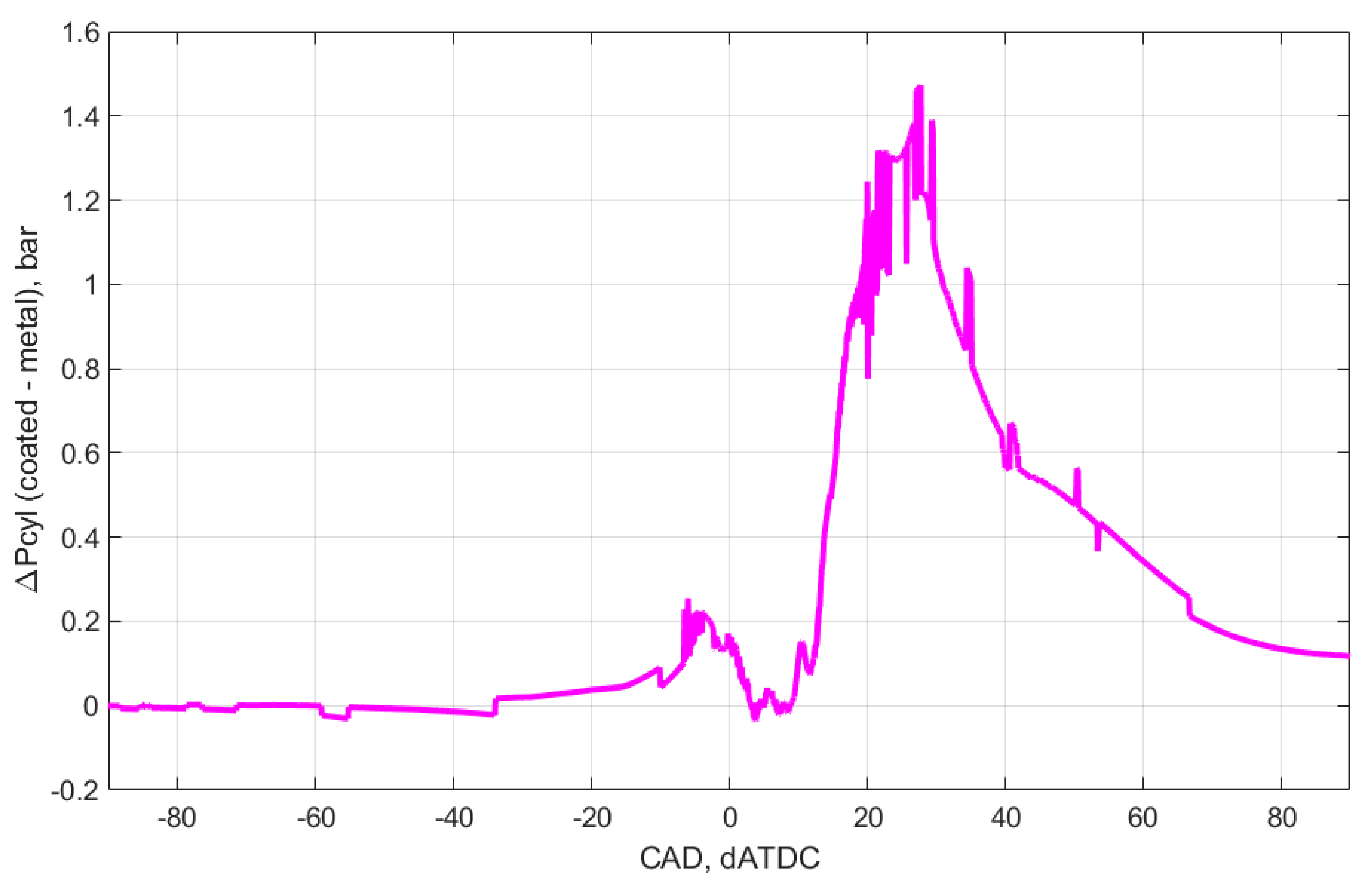
The cylinder pressure delta, shown in Figure 5, between the TBC and metal cases was near zero during gas exchange and compression. However, after the onset of combustion, the TBC case had a slightly higher in-cylinder pressure than metal, with a peak delta occurring at the end of combustion. The cylinder pressure consistency in the gas exchange portion of the cycle indicated that the TBC had no negative effects on the volumetric efficiency, and furthermore the trapped mass differential between the two cases was <0.5%. The bulk gas temperature showed a similar trend, wherein after the onset of combustion, the bulk gas temperature was higher for the TBC case than the metal, on the order of 10 K. These results indicate that the TBC did not affect the intake charge density through preheating, as well as the fact that the TBC was capable of targeted effects on the late compression/early expansion portion of the cycle through the coating temperature swing phenomenon.

Figure 5.
Cylinder pressure delta from the full load metal and TBC cases. The positive nature after combustion indicates that the coated piston simulation had a higher in-cylinder pressure from ≈10 degrees after top dead center to well after 80 degrees after top dead center. Consequently, expansion work can be expected to increase with the TBC.
On an instantaneous basis, shown in Figure 6, the deviation between the two cases for heat transfer losses showed similar phasing as the cylinder pressure. The reduction in heat transfer occurred between the onset of combustion through until approximately 45 degrees after top dead center (dATDC). The majority of heat transfer reduction from the TBC case was from the piston; however, a small fraction of the heat transfer reduction was also from the liner, while the cylinder head saw increased heat transfer losses for the TBC case. This was not a surprise, since the overall reduction of the heat loss leads to increased gas temperatures and therefore elevates convective heat loss through the metal surface of the cylinder head. This is an important observation that should be considered when planning the overall approach of coating application to the combustion chamber walls. Cumulatively, the heat transfer reduction for the entire cylinder was ≈10% of the baseline metal case.
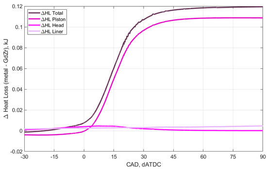
Figure 6.
Instantaneous cumulative heat transfer losses; combined (piston + head + liner) and component-wise heat transfer losses.
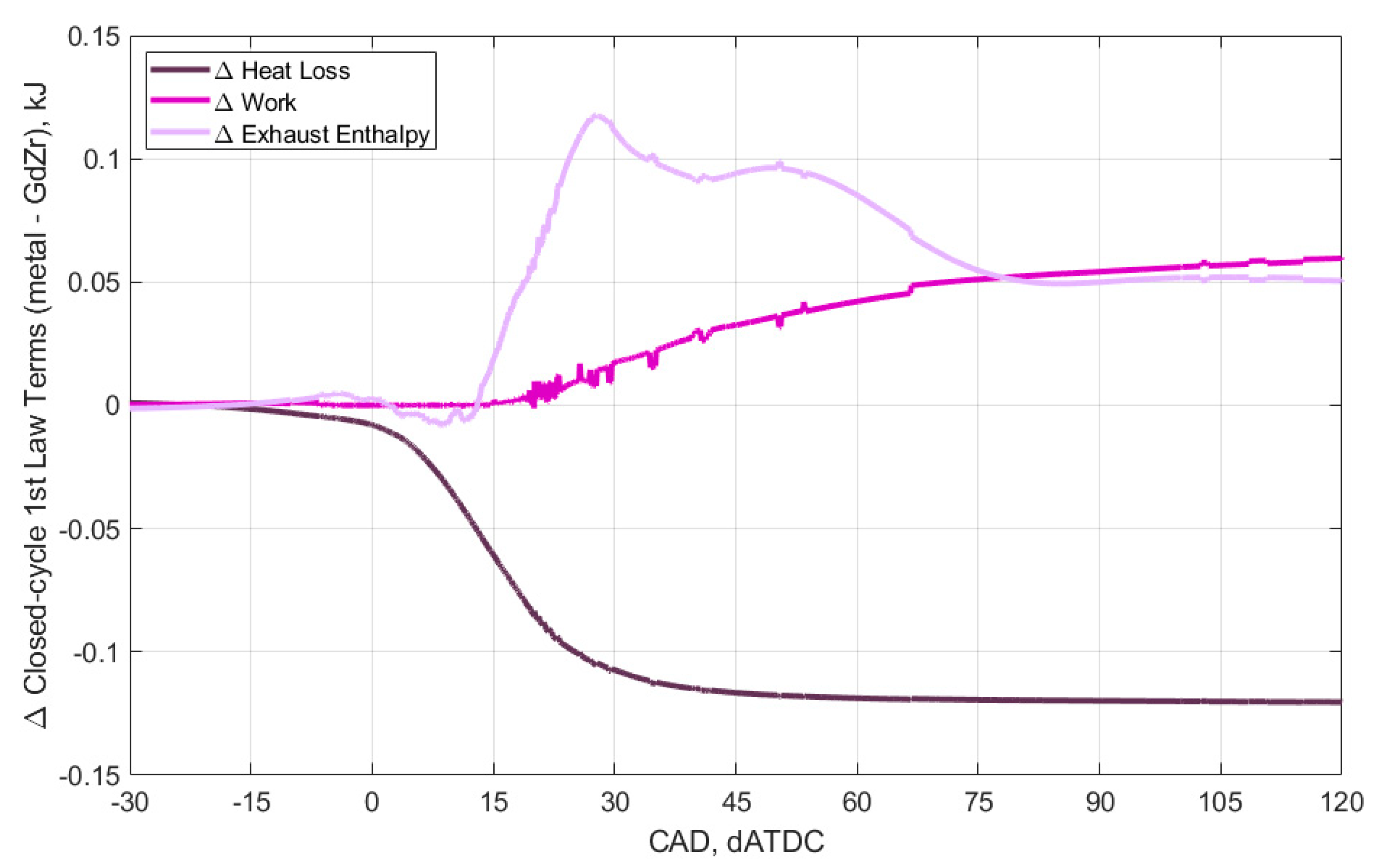
The closed cycle energy balance terms in Figure 7 confirm that the TBC did not demonstrate any significant impact from IVC through compression. For the TBC case after 0 dATDC, there was a near immediate and symmetric divergence between the increased delta in exhaust enthalpy (internal energy during closed portion) and decreased heat transfer delta. The work term increased more gradually, and at the end of combustion (≈20 dATDC), the internal energy and heat transfer losses began to stagnate, while the work delta continued to increase. During late combustion/expansion, there was a non-negligible increase in heat transfer to the cylinder head that was postulated to be an effect of the slightly increased gas temperatures within the combustion chamber. The delta for Figure 7 was the reverse of Figure 6, such that work and exhaust enthalpy are positive, and heat loss is shown as negative. By the end of the cycle, the decrease in heat transfer losses increased the exhaust enthalpy and work roughly evenly for the TBC case.
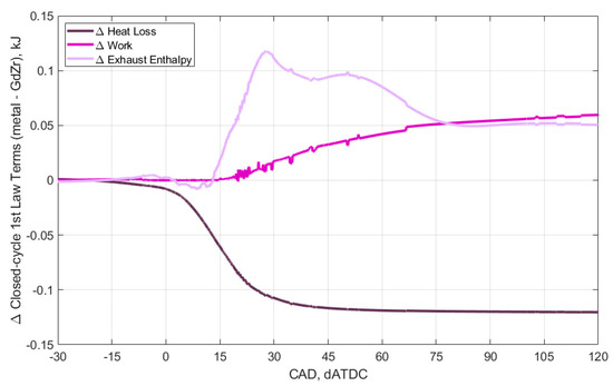
Figure 7.
Closed cycle first law analysis comparison for the TBC and metal cases, positive indicating that the metal case had higher values than the coated case.
4. Discussion
The framework developed in this study generated high fidelity spatially and temporally resolved surface temperature predictions for thermal barrier coatings in an MCC (diesel) engine. This methodology is critical for understanding the highly heterogenous heat transfer at the surface as well as the impact on combustion and expansion work. The main benefits of this methodology are the uncoupling of the solvers, allowing each to optimize the mesh density and time stepping routine, as well as the added capability to analyze the spatial and temporal temperature field and heat flux within the coating in detail. The methodology can be extended into investigations of future TBC materials, exploring the TBC design space and optimizing thermophysical properties as well as coating thickness to achieve desired heat transfer reductions.
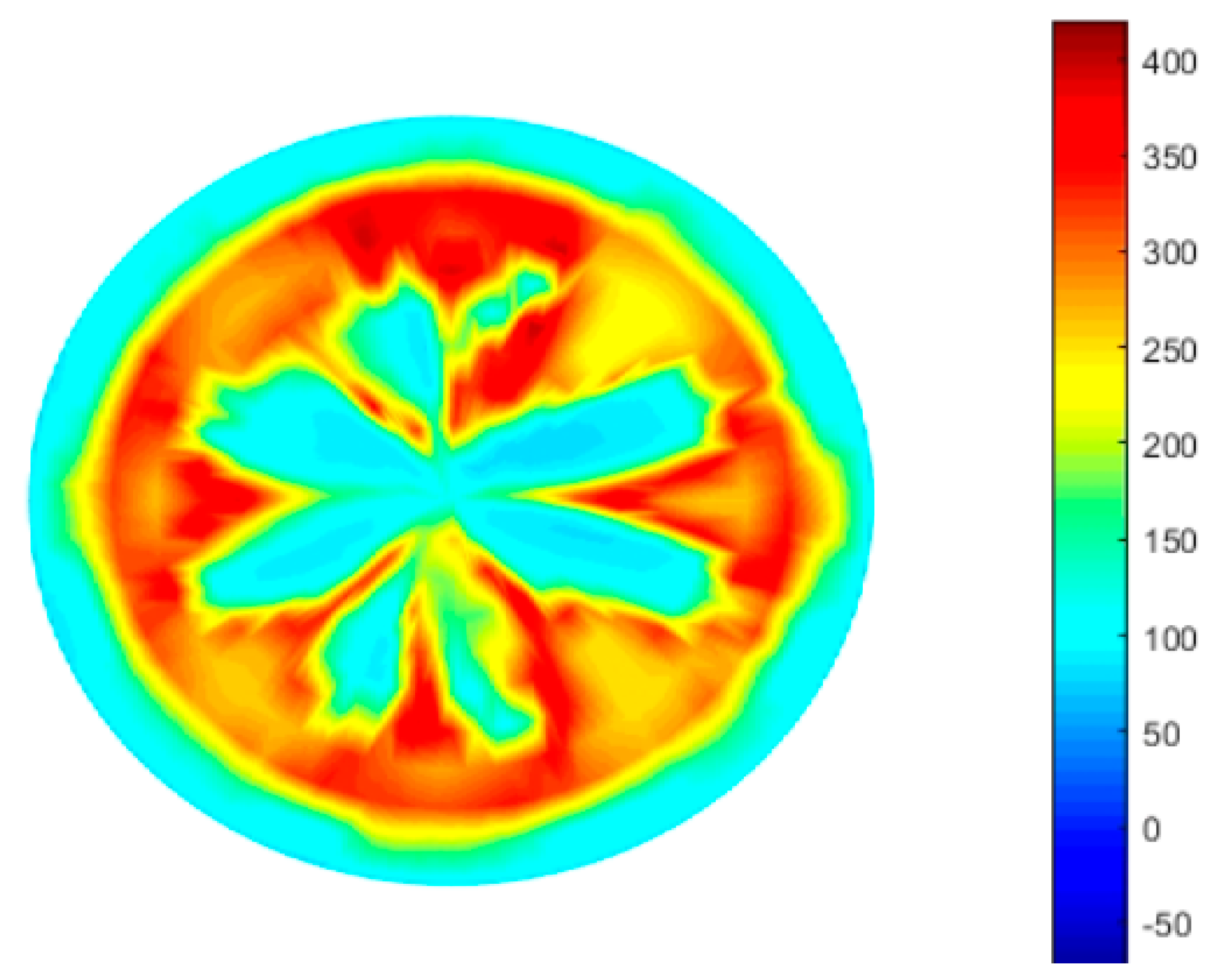
The tool adds capabilities to generate insights about the effect of a specific thermal barrier coating, as well as the ability to perform an inverse calculation and predict the necessary surface temperature swings to reach a target reduction in heat transfer losses and increased cycle work. As an example, the inverse processing was carried out with the newly developed tool to infer the required temperature swing for a 20% reduction in heat flux. This ultimately allowed for the reverse calculation of the material properties necessary to drive a desired reduction in heat transfer. The case study is illustrated in Figure 8, showing an estimated surface temperature requirement (deviation from 500K) at 10 dATDC firing. The calculation was performed assuming that a reduction to 80% of the heat transfer losses was needed for ≈1% improvement in the indicated work. Note that at this speed and load point, heat transfer losses for the baseline case were ≈10%, assuming the same 50/50 transfer of energy to exhaust vs. indicated work, a heat transfer reduction to roughly 8% was targeted. At each crank angle, equation 1 was solved, wherein Q represents the baseline heat flux multiplied by the reduction factor to identify the necessary temperature swing. This method is a quasi-steady state, as the energy transfer is not integrated over time (giving cycle cumulative heat transfer losses); rather, it is the required temperature at an “independent” snapshot in time.

Figure 8.
Required temperature swing (from 500K) to achieve a 20% reduction in heat flux at each nodal location, at crank angle 10 dATDC.
Figure 8 shows that for the CFD-predicted boundary conditions, wherein the surface temperature of the TBC needed to exceed 900K in some locations to reduce heat flux by 20%.
As shown in Section 3.1, a novel coating formulation can be engineered with the outlined framework by comparing predicted behavior of the novel coating to traditional coatings and ascertaining the impact on cycle efficiency.
5. Conclusions
A production-relevant DD13 HD diesel engine CFD and FEA model was developed to analyze the effects of a 100 µm gadolinium zirconate thermal barrier coating on heat transfer losses and combustion. A coupled methodology was developed that asynchronously linked the CFD model to the FEA solid model of the piston with, or without the TBC. Several iterations of boundary conditions were passed between the models until the surface temperature and combustion characteristics reached a steady state. The advantages are twofold: (i) accurate predictions of spatially resolved surface temperature swings and their impact on the cycle parameters, including thermal efficiency, and (ii) predictions of local extremes critical for assessing the risk of coating phase change or melting, impacting the selection of the coating material. This modeling methodology is novel in the sense that there is no averaging either spatially or temporally, and thus full resolution of the TBC effect can be modeled. The main enabler of this methodology is the uncoupling of the solvers, allowing each to optimize the mesh density and time stepping routine. The specific findings of this study are as follows:
- For the high load runs in this study, the surface temperature of the TBC reached 1200 K, achieving a dynamic surface temperature swing of 600 + K, compared to the metal piston with a maximum temperature of 550 K.
- The combustion phasing was not significantly affected by the addition of the TBC; however, the heat transfer losses were reduced by ≈10%.
- The heat transfer losses intracycle were significant during combustion and expansion, and there were no adverse effects on volumetric efficiency on the open cycle.
- The closed cycle analysis showed higher net work (1.2%) and exhaust enthalpy (1.04%) on a relative basis for the TBC case, indicating potential system level benefits for turbocharger, which was not modeled for this work.
- The framework developed allows for rapid exploration of the TBC design space through the use of an inverse process able to predict the required temperature swing to achieve a target heat loss reduction.
Author Contributions
Conceptualization, S.M. and Z.F.; methodology, S.M.; software, S.M. and K.D.E.; validation, S.M., and K.D.E.; formal analysis, S.M.; investigation, S.M. and K.D.E.; resources, Z.F., K.D.E., and T.S.; data curation, S.M.; writing—original draft preparation, S.M.; writing—review and editing, Z.F., T.S., and K.D.E.; visualization, S.M.; supervision, Z.F.; project administration, Z.F. and T.S.; funding acquisition, Z.F. All authors have read and agreed to the published version of the manuscript.
Funding
Funding for this project was provided from Daimler Trucks North America, as part of the DOE Supertruck 2 Program. Award Number DE-EE0007817, project ID ACS100.
Data Availability Statement
The data that was generated was deemed confidential as it is part of the ongoing super truck 2 effort (the application), however the source code for the mapping procedure (what this paper is truly about) is available by request.
Acknowledgments
Portions of this research were conducted by UT-Battelle, LLC, at Oak Ridge National Laboratory under contract DE-AC05-00OR22725 with the U.S. Department of Energy (DOE) and used resources at the National Transportation Research Center, a DOE Office of Energy Efficiency and Renewable Energy (EERE) User Facility at Oak Ridge National Laboratory. Funding was provided by the DOE Office of Vehicle Technologies via the Advanced Combustion Engine Manager Gurpreet Singh. Portions of this research used resources of the Compute and Data Environment for Science (CADES) at the Oak Ridge National Laboratory, which is supported by the Office of Science of the U.S. Department of Energy under contract no. DE-AC05-00OR22725. The authors would like to acknowledge Gurpreet Singh, Ralph Nine, and Ken Howden at the DOE Office of Vehicle Technologies, as well as members of the Daimler Supertruck II team, Craig Savonen, Jeffery Girbach, Marc Allain, Murad Bashir, and Nirmal Ettuparayil.
Conflicts of Interest
The authors declare no conflict of interest.
References
- Kamo, R.; Bryzik, W. Cummins/TACOM Advanced Adiabatic Engine; SAE International: USA, 1984; Available online: https://saemobilus.sae.org/content/840428/ (accessed on 6 April 2021).
- Beardsley, M.B.; Happoldt, P.G.; Kelley, K.C.; Rejda, E.F.; Socie, D.F. Thermal Barrier Coatings for Low Emission, High Efficiency Diesel Engine Applications; SAE International: USA, 1999; Available online: https://saemobilus.sae.org/content/1999-01-2255/ (accessed on 6 April 2021).
- Dickey, D. The Effect of Insulated Combustion Chamber Surfaces on Direct-Injected Diesel Engine Performance, Emissions and Combustion; SAE International: USA, 1989; Available online: https://saemobilus.sae.org/content/890292/ (accessed on 6 April 2021).
- Cheng, W.; Wong, V.; Gao, F. Heat Transfer Measurement Comparisons in Insulated and Non-Insulated Diesel Engines; SAE International: USA, 1989; Available online: https://saemobilus.sae.org/content/890570/ (accessed on 6 April 2021).
- Modi, A. Experimental Study of Energy Balance in Thermal Barrier Coated Diesel Engine; SAE International: Warrendale, PA, USA, 2012. [Google Scholar] [CrossRef]
- Kamo, R.; Assanis, D.; Bryzik, W. Thin Thermal Barrier Coatings for Engines; SAE International: USA, 1989; Available online: https://saemobilus.sae.org/content/890143/ (accessed on 6 April 2021).
- Kosaka, H.; Wakisaka, Y.; Nomura, Y.; Hotta, Y.; Koike, M.; Nakakita, K.; Kawaguchi, A. Concept of “Temperature Swing Heat Insulation” in Combustion Chamber Walls, and Appropriate Thermo-Physical Properties for Heat Insulation Coat. SAE Int. J. Engines 2013, 6, 142–149. Available online: https://saemobilus.sae.org/content/2013-01-0274/ (accessed on 6 April 2021). [CrossRef]
- Filipi, Z.; Hoffman, M.; O’Donnell, R.; Powell, T.; Jordan, E.; Kumar, R. Enhancing the efficiency benefit of thermal barrier coatings for homogeneous charge compression ignition engines through application of a low-k oxide. Int. J. Engine Res. 1 June 2020, 1–18. [Google Scholar] [CrossRef]
- Somhorst, J.; Uczak De Goes, W.; Oevermann, M.; Bovo, M. Experimental Evaluation of Novel Thermal Barrier Coatings in a Single Cylinder Light Duty Diesel Engine; SAE International: USA, 2019; Available online: https://saemobilus.sae.org/content/2019-24-0062/ (accessed on 6 April 2021).
- Kundu, P.; Scarcelli, R.; Som, S.; Ickes, A.; Wang, Y.; Kiedaisch, J.; Rajkumar, M. Modeling Heat Loss through Pistons and Effect of Thermal Boundary Coatings in Diesel Engine Simulations Using a Conjugate Heat Transfer Model; SAE International: USA, 2016; Available online: https://saemobilus.sae.org/content/2016-01-2235/ (accessed on 6 April 2021).
- Baldissera, P.; Delprete, C. Finite Element Thermo-Structural Methodology for Investigating Diesel Engine Pistons with Thermal Barrier Coating. SAE Int. J. Engines 2019, 12, 69–78. [Google Scholar] [CrossRef]
- Taibani, A.; Visaria, M.; Phalke, V.; Alankar, A.; Krishnan, S. Analysis of Temperature Swing Thermal Insulation for Performance Improvement of Diesel Engines. SAE Int. J. Engines 2019, 12, 117–127. [Google Scholar] [CrossRef]
- Killingsworth, N.; Powell, T.; O’Donnell, R.; Filipi, Z.; Hoffman, M. Modeling the Effect of Thermal Barrier Coatings on HCCI Engine Combustion Using CFD Simulations with Conjugate Heat Transfer; SAE International: USA, 2019; Available online: https://saemobilus.sae.org/content/2019-01-0956/ (accessed on 6 April 2021). [CrossRef]
- Buyukkaya, E.; Cerit, M. Thermal analysis of a ceramic coating diesel engine piston using 3-D finite element method. Surf. Coat. Technol. 2007, 202, 398–402. [Google Scholar] [CrossRef]
- Saad, D.; Saad, P.; Kamo, L.; Mekari, M.; Bryzik, W.; Schwarz, E.; Tasdemir, J. Thermal Barrier Coatings for High. Output Turbocharged Diesel Engine; SAE Technical Paper 2007-01-1442; SAE International: Warrendale, PA, USA, 2007. [Google Scholar] [CrossRef]
- Hejwowski, T. Comparative study of thermal barrier coatings for internal combustion engine. Vacuum 2010, 85, 610–616. [Google Scholar] [CrossRef]
- Converge Cfd; v2.4.; Convergent Science, Inc.: Madison, WI, USA, 2018.
- Reitz, R.D.; Bracco, F.V. Mechanisms of Breakup of Round Liquid Jets. In Encyclopedia of Fluid Mechanics; Gulf Publishing Company: Houston, TX, USA, 1986. [Google Scholar]
- Schmidt, D.P.; Rutland, C.J. A New Droplet Collision Algorithm. J. Comput. Phys. 2000, 164, 62–80. [Google Scholar] [CrossRef]
- O’Rourke, P.J.; Amsden, A.A. A Spray/Wall Interaction Submodel for the KIVA-3 Wall Film Model; SAE Paper 2000-01-0271; SAE International: Warrendale, PA, USA, 2000. [Google Scholar] [CrossRef]
- Amsden, A.A.; O’Rourke, P.J.; Butler, T.D. KIVA-II: A Computer Program for Chemically Reactive Flows with Sprays; Los Alamos National Laboratory: Los Alamos, NM, USA, 1989. Available online: https://www.osti.gov/biblio/6228444-kiva-ii-computer-program-chemically-reactive-flows-sprays (accessed on 6 April 2021).
- Senecal, P.K.; Pomraning, E.; Richards, K.J. Multi-Dimensional Modeling of Direct-Injection Diesel Spray Liquid Length and Flame Lift-off Length Using CFD and Parallel Detailed Chemistry; SAE International: Warrendale, PA, USA, 2003; Available online: https://saemobilus.sae.org/content/2003-01-1043/ (accessed on 6 April 2021).
- Babajimopoulos, A.; Assanis, D.N.; Flowers, D.L.; Aceves, S.M.; Hessel, R.P. A Fully Coupled Computational Fluid Dynamics and Multi-Zone Model with Detailed Chemical Kinetics for the Simulation of Premixed Charge Compression Ignition Engines. Int. J. Engine Res. 2005, 6, 497–512. Available online: https://journals.sagepub.com/doi/10.1243/146808705X30503 (accessed on 6 April 2021). [CrossRef]
- Gonera, M.; Sandin, O. Thermal Analysis of a Diesel Piston and Cylinder Liner Using the Inverse Heat Conduction Method. Master’s Thesis, Chalmers University, Göteborg, Sweden, 2015. Available online: https://hdl.handle.net/20.500.12380/220871 (accessed on 6 April 2021).
- Cerit, M.; Coban, M. Temperature and thermal stress analyses of a ceramic-coated aluminum alloy piston used in a diesel engine. Int. J. Therm. Sci. 2014, 77, 11–18. [Google Scholar] [CrossRef]
- Hohenberg, G.F. Advanced Approaches for Heat Transfer Calculations. SAE Trans. 1979, 88, 2788–2806. [Google Scholar]
- Woschni, G. A Universally Applicable Equation for the Instantaneous Heat Transfer Coefficient in the Internal Combustion Engine. SAE Trans. 1968, 76, 3065–3083. [Google Scholar]
- Binder, C.; Matamis, A.; Richter, M.; Norling, D. Comparison of Heat Losses at the Impingement Point and in between Two Impingement Points in a Diesel Engine Using Phosphor Thermometry; SAE International: Warrendale, PA, USA, 2019. [Google Scholar] [CrossRef]

Publisher’s Note: MDPI stays neutral with regard to jurisdictional claims in published maps and institutional affiliations. |
© 2021 by the authors. Licensee MDPI, Basel, Switzerland. This article is an open access article distributed under the terms and conditions of the Creative Commons Attribution (CC BY) license (https://creativecommons.org/licenses/by/4.0/).